EP1872913A2 - Werkzeughalter für einen Abbruchhammer - Google Patents
Werkzeughalter für einen Abbruchhammer Download PDFInfo
- Publication number
- EP1872913A2 EP1872913A2 EP07111161A EP07111161A EP1872913A2 EP 1872913 A2 EP1872913 A2 EP 1872913A2 EP 07111161 A EP07111161 A EP 07111161A EP 07111161 A EP07111161 A EP 07111161A EP 1872913 A2 EP1872913 A2 EP 1872913A2
- Authority
- EP
- European Patent Office
- Prior art keywords
- actuator
- tool holder
- tool
- housing
- flat
- Prior art date
- Legal status (The legal status is an assumption and is not a legal conclusion. Google has not performed a legal analysis and makes no representation as to the accuracy of the status listed.)
- Granted
Links
Images


Classifications
-
- B—PERFORMING OPERATIONS; TRANSPORTING
- B25—HAND TOOLS; PORTABLE POWER-DRIVEN TOOLS; MANIPULATORS
- B25D—PERCUSSIVE TOOLS
- B25D17/00—Details of, or accessories for, portable power-driven percussive tools
- B25D17/08—Means for retaining and guiding the tool bit, e.g. chucks allowing axial oscillation of the tool bit
- B25D17/082—Retainers consisting of a swinging yoke or latching means
-
- Y—GENERAL TAGGING OF NEW TECHNOLOGICAL DEVELOPMENTS; GENERAL TAGGING OF CROSS-SECTIONAL TECHNOLOGIES SPANNING OVER SEVERAL SECTIONS OF THE IPC; TECHNICAL SUBJECTS COVERED BY FORMER USPC CROSS-REFERENCE ART COLLECTIONS [XRACs] AND DIGESTS
- Y10—TECHNICAL SUBJECTS COVERED BY FORMER USPC
- Y10T—TECHNICAL SUBJECTS COVERED BY FORMER US CLASSIFICATION
- Y10T279/00—Chucks or sockets
- Y10T279/17—Socket type
- Y10T279/17042—Lost motion
- Y10T279/17051—Swinging external yoke or detent
Definitions
- the present invention relates to a hammer drill, and in particular to a pavement breaker, and more in particular to a tool holder for a pavement breaker.
- a hammer drill often has three modes of operation.
- Such a hammer drill typically comprises a spindle mounted for rotation within a housing which can be selectively driven by a rotary drive arrangement within the housing.
- the rotary drive arrangement is driven by a motor also located within the housing.
- the spindle rotatingly drives a tool holder of the hammer drill which in turn rotatingly drives a cutting tool, such as a drill bit, releasably secured within it.
- Within the spindle is generally mounted a piston which can be reciprocatingly driven by a hammer drive mechanism which translates the rotary drive of the motor to a reciprocating drive of the piston.
- a ram also slideably mounted within the spindle, forward of the piston, is reciprocatingly driven by the piston due to successive over and under pressures in an air cushion formed within the spindle between the piston and the ram.
- the ram repeatedly impacts a beat piece slideably located within the spindle forward of the ram, which in turn transfers the forward impacts from the ram to the cutting tool releasably secured, for limited reciprocation, within the tool holder at the front of the hammer drill.
- a mode change mechanism can selectively engage and disengage the rotary drive to the spindle and/or the reciprocating drive to the piston.
- hammer only mode where there is only the reciprocating drive to the piston
- drill only mode where there is only the rotary drive to the spindle
- hammer and drill mode where there is both the rotary drive to the spindle the reciprocating drive to the piston.
- EP1157788 discloses such a hammer.
- hammer drills While such hammer drills often comprise three modes of operation, it is also fairly common for hammer drills to only have either one or two modes of operation. For example, there are many types of hammer drills which only have drill only mode and which are more commonly referred to as a drill. One type of such a hammer drill is pavement breaker.
- a pavement breaker is a hammer drill having only a single mode of operation, namely that of hammer only mode (sometimes referred to as chisel mode).
- Pavement breakers tend to be relatively large hammer drills, the weight of which being capable of being used to assist in the operation of the pavement breaker. Though theoretically it is possible to fully support a pavement breaker in the hands of the operator, typically their weight prohibits this or at least limits the amount that this can be done. As such, when manually manoeuvred, pavement breakers are typically utilised in a downward projecting manner so that the tool held in the tool holder is in contact with the ground, the weight of the pavement breaker being transferred to the ground through the cutting tool.
- EP1475190 discloses a pavement breaker.
- a cutting tool such as a chisel
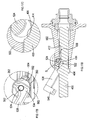
- Figures 1 to 6 show a typical prior art design of tool and tool holder for a pavement breaker.
- the tool comprises a working end (not shown) which engages with a work piece, such as a concrete floor, formed onto one end of a shank 400.
- the shank 400 has a hexagonal cross section in shape and a longitudinal axis 408.
- the other connection end 402, opposite to the working end, comprises a connection mechanism.
- the first type of connection mechanism is in the form of rib 404 formed around the circumference of the shank 400 and which is located at a predetermine distance from the remote end of the connection end 402 of the shank.
- the second type of connection mechanism is in the form of recess 406 formed on one side of the shank 400 along part of the length of the shank 400 at a predetermined distance from the remote end of the connection end 402 of the shank.
- the third type which is shown in Figure 1, comprises both the rib 404 and the recess 406.
- a tool with the first type of connection mechanism is intended to be used with a first type of tool holder which can engage with and hold the rib 404.
- a tool with the second type of connection mechanism is intended to be used with a second type of tool holder which can engage with the recess 406 to hold the tool.
- a tool with the third type of connection mechanism is intended to be used with either the first type of tool holder capable of holding a tool with the first type of connection mechanism, the second type of tool holder capable of holding a tool with a second type of connection mechanism, or a tool holder capable of holding a tool with the third type of connection mechanism.
- the tool holder 500 comprises a tool holder housing 502 which is formed from a single metal cast which is attached to a middle housing 504 using a series of standard bolts 506.
- a plurality of holes 508 are formed through a flange 510 formed around the upper end of the tool holder housing 502.
- Corresponding holes 512 are formed through the base 514 of the middle housing 504.
- the bolts 506 pass through the holes 508 in the flange 510 of the tool holder housing 502 and then through the holes 512 through the base 514 of the middle housing 504.
- Standard nuts 518 are screwed onto the ends of the bolts 506 adjacent the base 514 of middle housing 516 to secure the tool holder housing 502 to the middle housing 504.
- a tubular recess 520 of hexagonal cross section which is intended to receive the connection end 402 of the shank 400.
- a tubular passageway 522 is formed across the width of the tool holder housing 502.
- the cross sectional shape of the tubular passageway 522 is oval.
- the tubular passageway 522 intersects the top part of the tubular recess 520 at its centre.
- a metal rod 524 passes through the full length of the tubular passageway 522, the ends 526 extending outwardly on either side of the tool holder housing 502.
- the centre 560 of the metal rod 524 comprises a circular groove 528 formed widthways, the maximum depth of which at its centre being half that of the width of the metal rod 524.
- the centre of the metal rod 524, which includes the groove 528 is located in and traverses across the top part of the tubular recess 520.
- the metal rod 524 can freely rotate about its longitudinal axis 530 within the tubular passageway 522, the longitudinal axis 530 of the metal bar 524 being parallel with that of the tubular passageway 522.
- the oval shape of the passageway enables the bar 524 to slide in a direction (indicated by Arrow M) parallel to that of the longitudinal axis 408 of the tool when the tool is located within the tool holder 500.
- the U shaped clamp 532 comprises two ends 534 which are in the form of rings.
- the two bar holes 536 of the rings 534 are co-axial and face each other.
- Attached to each end ring 534 is a curved arm 538.
- the ends of both the curved arms 538 connect to a semi-circular hook 540 as best seen in Figure 100.
- the inner diameter of the hook 540 is greater than that of the shank 400 but less than that of the rib 404 of the tool.
- the end rings 534, the curved arms 538 and the hook 540 are manufactured from steel in a one piece construction.
- Holes 542 are formed through the ends 526 of the metal bar 524, the axes of the holes 542 being parallel to each other and perpendicular to the longitudinal axis 530 of the metal bar 524.
- Holes 544 are formed through the end rings 534 of the U shaped clamp 532, the axes of the holes 544 being parallel to each other and perpendicular to the axis of the bar holes 536 of the end rings 534.
- the ends of the metal bar 524 locate within the bar holes 536 of the end rings 534 and orientated so that holes 542 of the metal bar 524 and the holes 544 of the end rings 534 are aligned (see Figure 4).
- a pin passes through each set of aligned holes 542, 544 to rigidly attach the end rings 534 to the ends 526 of the metal bar 524.
- the metal rod 524 is held within tubular passageway 522 by two compressible rubber rings 546 which locate within cavities 548 formed in the side of the tool holder housing 502 (see Figure 1).
- the rubber rings 546 bias the metal rod 524 to a central location within the tubular passageway 522.
- the metal rod 524 can be moved within the oval tubular passageway 522 in a direction (Arrow M) parallel to the longitudinal axis 408 of the tool.
- the U shaped clamp 532 pivots, in unison with the metal rod 524, about the longitudinal axis 530 of the metal rod 524. Pivotal movement of the U shaped clamp 532 locks the tool 400 within the tool holder or releases it.
- the U shaped clamp 532 itself is used to hold a tool with the first type of connection mechanism by engaging with the rib 404 of the tool.
- the U shaped clamp 532 is pivoted to a position where the tubular recess 520 is exposed. (It should be noted that U shaped clamp 532 will be in a position where the circular groove 528 of the metal bar 524 faces towards the tubular recess 520 so that the metal bar 524 does not interfere with the insertion of the connection end 402 of the tool).
- the connection end 402 of the tool is inserted into the tubular recess 520 until the rib 404 engages with the nose 550 of the tool holder housing 502.
- the U shaped clamp 532 is then pivoted until the hook 540 of the U shaped clamp 532 surrounds the shank 400 of the tool below the rib 404. In this position, the rib 404 is prevented from travelling past the hook 540 of the U shaped clamp 532. As the connection end 402 of the tool slides out of the tubular recess 520, the rib 404 engages with the hook 540 of the U shaped clamp 532 and is then prevented from travelling further. As such, the connection end 402 of tool is held within the tubular recess 520 whilst being able to slide axially over a limited range of travel, the range of movement being the distance the rib 404 can slide between the nose 550 and the hook 540 (as best seen in Figure 3). To release the tool, the U shaped clamp is pivoted so that the hook is removed from the path way of the rib 404, to allow the connection end 402 to fully slide out of the tubular recess 520.
- a first locking mechanism is provided for U shaped clamp 532 so that, when the hook surrounds the shank 400 to lock the tool within the tool holder, the U shaped clamp 532, including the hook 540, is locked in that position to prevent the tool inadvertently being released from the tool holder.
- Formed on the periphery of the two rings 534 of the U shaped clamp 532 are first flat locking surfaces 552.
- Formed on the tool holder housing 502 are corresponding flat holding surfaces 554.
- the flat locking faces 552 and the flat holding surfaces 554 are aligned with each other and are biased together by the rubber rings 546 (which biases the metal bar 524 in the direction of Arrow M to a central position within the tubular passageway 522) so that they abut against each other (see Figure 5 - solid lines).
- the rings 534 are prevented from rotating.
- the U shaped clamp 532 has to move axially (direction of Arrow M) to allow the flat locking faces 552 to pivot relative to the flat holding surfaces 554 (see dashed lines in Figure 5).
- the axial movement (Arrow M) of the U shaped clamp 532 is achieved by the compression of the rubber rings 546 within the cavities 548 which allow the metal bar 524 to slide within the oval tubular passageway 522. Pivotal movement of the U shaped clamp 532 causes the rubber rings 546 to compress, allowing the first flat locking surfaces 552 to ride over the flat holding surfaces 554. The biasing force of the rings 546 hold the locking surfaces 552 against the holding surfaces 554 and hence lock the U shaped clamp 532 in the locking position.
- the metal rod 524 itself is used hold a tool with the second type of connection mechanism by engaging with the recess 406 of the tool.
- the metal rod 524 is pivoted to a position where the U shaped clamp 532 is located away from the location of the tool, leaving the recess 520 exposed.
- the precise position of the U shaped clamp 532 is such that the circular groove 528 of the metal bar 524 faces into the tubular recess 520. As such, there are no restrictions within the tubular recess 520 to prevent the connection end 402 of the tool 400 fully entering the tubular recess 520.
- connection end 402 of the tool is fully inserted into the tubular recess 520. It has to be ensured that the recess 406 of the tool 400 faces upwards towards the metal bar 524. (It should be noted that the tool can not be rotated within the recess 520 due to the cross sectional shapes of the shank 402 and the recess 520.)
- connection end 402 of the tool 400 When the connection end 402 of the tool 400 is fully inserted into the tubular recess 520, that the groove 528 of the metal bar 524 faces into recess 406 of the tool.
- the U shaped clamp 532 is then pivoted, causing the metal bar 524 to pivot, until the groove 528 of the metal bar 524 faces away from the recess 406 of the tool.
- the central part 560 of the metal bar 524 faces towards and locates within the tubular recess 520 of the tool holder and thus faces towards and locates within the recess 406 of the tool 400. This is best seen in Figure 2.
- connection end 402 of the tool slides out of the tubular recess 520, the upper edge 412 engages with the central part 560 of the metal bar 524 and is then prevented from travelling further.
- the connection end 402 of tool is held within the tubular recess 520 whilst being able to slide axially of a limited range of travel, the range of movement being the distance the central part 560 can slide between the upper 412 and lower 414 edges of the recess 406 (as best seen in Figure 2).
- the U shaped clamp 532 is pivoted in order to pivot the metal bar 524 in order to remove the central part 560 of the metal bar 524 from the recess 406 of the tool 400, which allows the connection end 402 of the tool to fully slide out of the tubular recess 520.
- a second locking mechanism is provided for U shaped clamp 532 so that, when the central part 560 of the metal bar 524 is located within the recess 406 of the tool 400 to lock the tool 400 within the tool holder, the U shaped clamp 532, including the metal bar 524, is locked in that position to prevent the tool inadvertently being released from the tool holder.
- Formed on the periphery of the two rings 534 of the U shaped clamp 532 are second flat locking surfaces 562. As described previously, formed on the tool holder housing 502 are flat holding surfaces 554.
- the second flat locking faces 562 and the flat holding surfaces 554 are aligned with each other and are biased towards each other by the rubber rings 546 so that they abut against each other (see Figure 6 - solid lines).
- the rings 534 are prevented from rotating.
- the U shaped clamp 532 has to move axially (direction of Arrow M) to allow the second flat locking faces 562 to pivot relative to the flat holding surfaces 554 (see dashed lines in Figure 6).
- the axial movement of the U shaped clamp 532 is achieved by the compression of the rubber rings 546 within the cavities 548 which allow the metal bar 524 to slide within the oval tubular passageway 522. Pivotal movement of the U shaped clamp 532 causes the rubber rings 546 to compress, allowing the second flat locking surfaces 562 to ride over the flat holding surfaces 554. The biasing force of the rings 546 hold the second locking surfaces 562 against the holding surfaces 554 and hence lock the U shaped clamp 532, and hence the metal bar 524, in the locking position.
- Such a tool holder can hold all tools with any of the three types of connection mechanisms.
- the beat piece 564 repeated strikes the connection end 402 of the tool 400.
- the diameter of the head 566 of the beat piece 564 is greater than that of the tubular recess 520 required to receive the connection end 402 of the tool 400.
- the top end 568 of the tubular recess 520 has an increased diameter to enable the head 566 of the beat piece 564 to travel along the length of the top end 568 of the tubular recess 520.
- Rearward, upward movement of the beat piece 564 along the axis 570 is limited by a rear shoulder 576 of the head 566 of the beat piece 564 engaging with an upper stop 578 formed on a side of a metal ring 580 rigidly attached to the top end of the tool holder housing 502.
- the tool holder and beat piece 564 support structure which includes the top end section 568 of the tubular recess 520 and the metal ring 580, are designed so that when it used to hold a tool having the first type of connection mechanism, the rib 404 is always able to engage with the nose 550 of the tool holder housing 502.
- the connection end 402 of the tool 400 When the connection end 402 of the tool 400 is inserted into the tubular recess 520, it engages with the head 566 of the beat piece 564, which is biased downwardly due to gravity, and pushes it upwardly. As the connection end 402 slides into the tubular recess 520, it pushes the beat piece upwardly against the biasing force of gravity.
- the design of the tool holder and beat piece 564 support structure is arranged so that the rib 404 always engages with the nose 550 of the tool holder housing 502 prior to the rear shoulder 576 of the head 566 of the beat piece 564 engaging with the upper stop 578 formed on a side of the metal ring 580 rigidly attached to the top end of the tool holder housing 502.
- the U shaped clamp is only capable of being locked in positions where it is holding a tool (whether it holding a tool having the first type of connection mechanism using the hook 540 to hold the rib 404 or a tool having the second type of connection mechanism where the centre 560 of the metal bar 524 locates within the recess 406).
- the U shaped clamp 532 is not locked and as such, can freely pivot. This causes problems to the user when the user is trying to change the tool.
- Pavement breakers generate a great deal of vibration during its operation.
- One method of achieving this is to use a dampening mechanism to counteract the vibration generated by the operation of the pavement breaker.
- EP1252976 discloses a hammer drill having such a dampening mechanism.
- EP1252976 shows a hammer drill having a cylinder, a piston reciprocatingly driven within the cylinder by a motor, a ram slideably mounted within the cylinder which is reciprocatingly driven by the piston via an air spring, and a beat piece which is repetitively struck by the ram and which, in turn, strikes an end of a cutting tool, such as a chisel, held within a tool holder.
- An oscillating counter mass is used to reduce vibration within the hammer drill.
- the counter mass surrounds and is slideably mounted on the cylinder and is held between two springs which bias the counter mass to a predetermined position on the cylinder.
- the mass of the counter mass and the strength of the springs are such that, when the hammer drill is operated, the counter mass vibrates out of phase with the piston and ram so that it counteracts the vibration generated by the operation of the hammer drill.
- US 2230046 discloses a drill steel retainer which can be maintained in its released position by means of a resilient member acting on a retainer yoke.
- a drill steel retainer suffers from a number of drawbacks. For example, it can only retain a tool of one type, and the dimensions of the resilient member must closely match those of the retainer yoke, which adds to the difficulty and cost of manufacture of the retainer.
- a tool holder for a hammer apparatus comprising:
- Such a design of tool holder enables a tool to be inserted into or removed from the tool holder by an operator with greater ease and for a number of different types of tool.
- a tool holder for a hammer apparatus comprising:
- Such a design of tool holder enables a tool to be inserted into or removed from the tool holder by an operator with greater ease.
- the provision of biasing devices to mount each end of the rod to the tool enables manufacturing tolerances between the rod, biasing devices and actuator body to be taken up, which means that the dimensions of the biasing devices do not need to closely match those of the actuator. This in turn reduces the cost and difficulty of manufacturing a tool incorporating the tool holder.
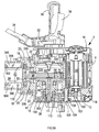
- the pavement breaker consists of an upper housing 2, a middle housing 504, and a tool holder housing 502. (Where the same features are present in the present embodiment of the pavement breaker which are also present in the tool holder described above with reference to Figures 1 to 6, the same reference numbers have been used. However, where there are new features are present which are similar, but not the same as previous features, new reference numbers have been allocated. New features will also have new reference numbers.)
- the upper housing 2 consists of a central clamshell 8, and two side clamshells 10, one attached to each side of the central clamshell 8 by a plurality of screws 14. Attached to each side clamshell 10 is a handle 16 by which an operator supports the pavement breaker during use.
- the middle housing 504 comprises a single metal cast which is attached to the upper housing 2 using a series of bolts 18 which pass through apertures formed through a flange 20 located at the upper end of the middle housing 504 and threadably engage in threaded holes formed in the lower end 22 of the central clamshell 8 of the upper housing 2.
- the tool holder housing 502 comprises a single metal cast which is attached to the middle housing 504 using a series of bolts 24.
- a plurality of holes 508 are formed through a flange 510 formed around the upper end of the tool holder housing 502.
- Corresponding holes 512 are formed through the base 514 of the middle housing 504.
- the bolts 24 pass through the holes 508 in the flange 510 of the tool holder housing 502 and then through the holes 512 through the base 514 of the middle housing 504.
- self locking Heli-coil nuts 30 are screwed onto the ends of the bolts 24 adjacent the base 514 of middle housing 504 to secure the tool holder housing 502 to the middle housing 504.
- a rubber seal 82 is provided between the tool holder housing 502 and the middle housing 504.
- a Heli-coil ⁇ is shown in Figure 11D. It comprises a coil of wire.
- the coil of wire comprises an upper section 304, a middle coil 306 and a lower section 308.
- the upper 304 and lower 308 sections comprise coils which follow a circular path.
- the middle coil comprises a series of straight segments to form a hexagonal path.
- a Heli-coil ⁇ nut comprises a standard design of nut 310 having a threaded passageway passing through it in conventional manner.
- a Heli-coil ⁇ having a coil of wire with the same pitch of thread as the thread of the nut and which is made from wire which has a diameter corresponding to the dimensions of the grooves of the thread of the nut, is located within the thread 312 of the nut 310.
- the Heli-coil® now acts as the thread for the nut 310.
- the middle coil 306 provides the Hel-coil® nut with self locking feature so that when it is screwed onto a bolt it grips onto the bolt and prevents the Heli-coil® nut from unscrewing.
- the reason why the middle coil provides the self locking feature is that it has a hexagonal shape where as the cross sectional shape of the shaft of a bolt is round. As such, the middle coil exerts a gripping force onto the shaft of a bolt when is screwed onto the shaft.
- the Heli-coil ⁇ spreads out the stress placed onto the thread of the nut across all of the thread within the nut rather than exerting stress onto one part of the thread.
- an electric motor 32 which is powered by an electricity supply provided from an electric cable 34 which connects to the motor 32 with the via an electric switch 33.
- a pivotal lever 36 connected to the switch, is located on a handle 16. Depression of the lever 36 activates the electric motor 32.
- the electric motor 32 rotating drives a crankshaft 38 via a plurality of gears.
- the splined output shaft 100 of the motor 32 rotatingly drives a first gear 102 which is rigidly mounted on a rotatable shaft 104.
- the rotable shaft 104 is rotationally mounted within the upper housing 2 via a bearing 116.
- a second gear 106 is also rigidly mounted on the rotatable shaft 104, adjacent the first gear 102, such that rotation of the first gear about the longitudinal axis 108 of the rotatable shaft 104 results in rotation of the second gear 106 about the longitudinal axis 108 at the same rate as the first gear 102.
- the second gear 106 meshes with a third gear 110 which is rigidly mounted onto the end of the crank shaft 38.
- the crank shaft 38 is rotatably mounted in the upper housing 2 via two sets of bearings 112, 114.
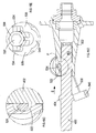
- Figure 12 shows a perspective view of the crank.
- the crank 40, 42, 38 is integrally formed in a one piece construction. Rotation of the crankshaft 38 causes the longitudinal axis 44 of the drive pin 40 to rotate about the longitudinal axis 46 of the crankshaft 38 in well known manner.
- the platform 42 comprises a semi-circular section 314 and a raised section 316 on which is mounted the drive pin 40. The mass of the semi-circular section 314 counteracts the forces applied to the crank due via the pin 40 when the crank rotates.
- a tubular passageway 300 extends through the full length of the crank shaft 38 to allow the passage of air and lubricating grease through the length of the crank shaft 38, enabling them to more easily move within the upper housing 2.
- a tubular passageway 302 extends through the full length of the drive pin 40, again to allow the passage of air and lubricating grease through the length of the drive pin 40, enabling them to more easily move within the upper housing 2.
- a lubrication groove 318 is formed in the raised section 316 which extends radially outwardly from the longitudinal axis 46 of the crank shaft 38 from the end of the raised section to the drive pin 40 as shown in Figure 12. The function of the lubrication groove 318 is described in more detail below.
- the oil cap 320 clips into the end of the crank shaft 38 as shown n Figure 9A.
- the oil cap 320 comprises a tubular body 322 and a flat end cap 324 attached to one end.
- the tubular body 322 has a passageway 326 through its length, its base 332 being open.
- the end cap 324 comprises a tubular passageway 328 which extends from one side of the perimeter of the end cap 324 to the passageway 326 within the tubular body 322. This provides a passageway from the edge of the end cap 324 to the base 332 of the tubular body 322 which allows the passage of lubricating oil through the oil cap 320.
- the tubular body of the oil cap locates in the tubular passageway 300 of the crank shaft 38, the end cap 324 abutting against the end of the crank shaft.
- the oil cap 320 is orientated so that the tubular passageway 328 points towards the drive pin 40 and so that it points towards and is in line with the lubrication groove 318.
- An arrow 330 indicates the direction of the tubular passageway for ease of assembly.
- a con rod 48 is rotationally attached at one of its ends to the drive pin 40 via drive bearings 334.
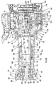
- the other end of the con rod 48 is pivotally attached to a piston 50 which is slideably mounted within a cylinder 52 rigidly mounted within the middle housing 504. Rotation of the crankshaft 38 results in a reciprocating movement of the piston 50 within the cylinder 52.
- a ram 54 is located within the cylinder 52 and is capable of freely sliding within the cylinder 52. Piston rings surround the piston 50 to prevent air within the cylinder passing the piston 50. Similarly, piston rings surround the ram 54 to prevent air within the cylinder passing the ram 54. Therefore, the reciprocating movement of the piston 50 reciprocatingly drives the ram 54 within the cylinder 52 via an air spring 56 formed between the piston 50 and ram 54. An air hole 100 is formed in the wall of the cylinder 52. Once the ram 54 has passed the air hole 100 travelling away from the piston 50, as shown in Figure 9B, air is able to leave or enter the space within the cylinder 52 between the ram 54 and the piston 50.
- the ram 54 when reciprocatingly driven by the piston 50, repeatedly strikes a beat piece 58 which is supported by a beat piece support structure which is sandwiched between the upper end of the tool holder housing 502 and lower end of the middle housing 504.
- a recess 60 is formed in the lower end of the ram 54.
- the top end of the beat piece 58 is struck by the base 62 of the recess 60. This reduces the overall length of the striking mechanism whilst maximising the stroke length (the maximum axial distance travelled by the ram within the cylinder 52) of the ram 54.
- the beat piece support structure comprises a shaped circular tubular metal support 64 having a tubular passageway, of uniform circular cross section, formed through its length.
- the lower end of the shaped circular tubular metal support 64 is located within a circular recess within the upper end of the tool holder housing 502.
- a rubber dampener 66 is sandwiched between a radial step 68 formed on the shaped circular tubular metal support 64 and the middle housing 504.
- a guide 70 is sandwiched between the tool holder housing 502 and the shaped circular tubular metal support 64.
- the beat piece 58 comprises a cylindrical shank 72, a radial bulge 74 and a nose 76 as best seen in Figure 10.
- the radial shank 72 locates within the tubular passageway of the shaped circular tubular metal support 64 and is capable of sliding along its longitudinal axis 78 within the tubular passageway.
- Seals 80 are provided within the wall of the tubular passageway which engage with the sides of the cylindrical shank 72 of the beat piece 58 to prevent dust etc from passing through the tubular passageway of the shaped circular tubular metal support 64 into the middle housing 504.
- the rear ward (upward) movement (to the right in Figures 9B and 9C) is limited by the rear shoulder 84 of the radial bulge 74 engaging with an angled face 86 of the shaped circular tubular metal support 64.
- the forward (downward) movement (to the left in Figures 9B and 9C) is limited by the front shoulder 88 of the radial bulge 74 engaging with an angled face 90 formed within of the tool holder housing 502.
- the tool holder housing 502 forms the main support structure of the tool holder in which can be held a tool, such as a chisel.
- the ram 54 when reciprocatingly driven by the piston 50, repeatedly strikes the end of the shank 72 of the beat piece 58, the nose 76 of which, in turn, repetitively strikes the end of the tool held within the tool holder.
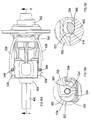
- This pavement breaker comprises a dampening mechanism which counteracts the vibration generated by the operation of the pavement breaker.
- the dampening mechanism comprises a tubular counter mass 102 of circular cross section which surrounds the cylinder 52.
- the tubular counter mass 102 is made from a magnetic material (or, alternatively, includes a permanent magnet built into the counter mass) for purposes described in more detail below.
- the tubular counter mass 102 is slideably mounted on the cylinder 52 via two guide rings 104, 106.
- the first guide ring 104 is rigidly attached to the lower end of the tubular counter mass 102
- the second guide ring 106 is rigidly attached to the upper end of the tubular counter mass 102.
- the two guide rings 104, 106 are mounted directly on the cylinder and side along the surface of cylinder 52.
- the inner diameter of the tubular counter mass 102 is greater than that of the outer diameter of the cylinder 52. This results in a space 108 being formed between the tubular counter mass 102 and the outside of the cylinder 52.
- the guide rings 104, 106 maintain the size of this space 108 , ensuring that the counter mass 102 does not come into contact with the cylinder 52.
- a lubricating oil surrounds the cylinder 52 and reduces friction between the guide rings 104, 106 and the outside surface of the cylinder 52 as the guide rings 104, 106 slide along the surface.
- the tubular counter mass 102 is biased to a central position between two helical springs 110, 112 which surround the cylinder 52.
- the first helical spring 110 is sandwiched between the second guide ring 106 and the central clam shell 8 of the upper housing 2.
- the second helical spring 112 is sandwiched between the first guide ring 104 and a recess formed within the middle housing 502.
- the pavement breaker As the pavement breaker operates, it generates vibration.
- the vibration causes the counter mass 102 to oscillate backwards and forwards along the cylinder 52.
- the strength of the two springs 110, 112 and the weight of the mass 102 are arranged so that the counter mass 102 vibrates out of phase with the rest of the pavement breaker, the resulting motion reducing the size of vibration experienced by the body of the pavement breaker and thus producing a dampening effect.
- pavement breaker In order for the pavement breaker to operate efficiently, its internal components must be lubricated using a lubrication oil which is capable of freely flowing internally around the component parts of the pavement breaker to reduce friction, wear and tear.
- a lubrication oil which is capable of freely flowing internally around the component parts of the pavement breaker to reduce friction, wear and tear.
- One of the problems of pavement breakers is to ensure that there is a dispersement of the lubricating oil across the component parts.
- the present pavement breaker utilises the movement of its component parts to distribute the lubricating oil to the areas where it is required.
- the electric motor 32 rotating drives the crankshaft 38 via the gears 102, 106, 110 which inturn reciprocatingly drives the piston 50 in well known manner.
- the size of the space 336 behind the piston 50 continuously fluctuates.
- the amount of air capable of being located within the space336 in the cylinder 52 behind the piston 50 also continuously alters. As such, air is sucked from inside the upper housing 2 into the top of the cylinder 52 behind the piston 50 as the volume of the space 336 increases and is blown out from the top of the cylinder 52 into the upper housing 2 as the volume of the space 336 decreases. This results in large air movements within the upper housing 2.
- the tubular counter mass 102 slides in an oscillating fashion along the outside of the cylinder 52 to perform its dampening function.
- the lubricating oil coats all of the internal parts of the pavement breaker including the crank shaft 38, the drive pin 40, the con rod 48, the rear of the piston 50, the outside of the cylinder 52, the counter mass 102 and the springs 110, 112.
- the large air movements within the upper housing 2 caused by the reciprocating movement of the piston 50 within the cylinder 52 causes air, and oil entrained within the air, typically in the form of a spray, to move through the tubular passageway 300 of the crank shaft 38 in alternate directions as the air is repetitively drawn into and expelled from the space 336 in the cylinder 52 behind the piston 50.
- the generation of oil spray can be caused by the movement of the crank 38, 40, 42, the con rod 48, the gears 102, 106, 110 and the piston 50.
- the tubular passageway 300 of the crank shaft 38 enable easy movement of air and lubricating oil within the upper housing as the air fluctuates due to the reciprocating piston 50.
- Lubrication is provided by the provision of the oil cap 320 and the lubrication groove 318.
- the oscillating movement of the counter mass 102 also causes air movement within the space 340 around the cylinder 52 within the middle housing 502. Furthermore, the oscillating movement of the counter mass 102 causes the oil to become a spray. The air movement causes the generated lubrication oil spray to circulate within the space 340 within middle housing 502 surrounding the cylinder 52.
- a curved passageway way 344 is formed in the base of the middle housing 504 which directs air and entrained lubricating oil into the lower cylinder space 342.
- the counter mass 102 moves downwardly towards the tool holder, it pushes air and entrained lubricating oil into the curved passageway 344 which directs into the lower cylinder space 342 due to it shape.
- the counter mass 102 moves upwardly away from the tool holder, it draws air and entrained lubricating oil out of the lower cylinder space 342 through the curved passageway 344.
- the movement of the air and entrained lubricating oil into and out of the lower cylinder space 342 is also assisted by the movement of the ram 54 within the cylinder 52 increasing or decreasing the lower cylinder space 342, causing pressure fluctuations resulting in air movement.
- the movement of the ram 54 is out of phase to that of the counter mass 102 such that their respective movements co-operate in the movement of air and entrained lubricating oil into and out of the lower cylinder space 342.
- Channels are formed between the space 340 around the cylinder 52 within the middle housing 504 and the area 338 adjacent the con rod 48 to enable the passage of air and entrained lubricating oil between the two.
- the gears 102, 106, 110 may have an addition thick grease as a lubricant which is applied to the components when assembled and reapplied during maintenance. This thick grease is too viscous to be moved by the air fluctuations within the pavement breaker. However, over time, there will be some mixing of the lubricating oil and the thick grease as the lubricating oil is circulated within the pavement breaker.
- the tool holder 94 is similar to the prior art one described above with reference to Figures 1 to 6. Where the same features are present in the present embodiment of tool holder as that in the prior art tool holder described above with reference to Figures 1 to 6, the same reference numbers have been used.
- Figures 14A to 14D and Figures 15A to 15E show the tool holder only, when it used to hold a tool with the first type of connection mechanism using the U shaped clamp 532 to engage with the rib 404 of the tool.
- the mechanism by which the tool is secured into the tool holder is the same as that of the prior design as described above with reference to Figures 1 to 6.
- Figures 14A to 14D show the tool holder holding the connection end 402 of the tool within the tool holder.
- the hook 540 surrounds the shank 400 of the tool and is so positioned that it prevents the connection end 402 of the tool from sliding out of the recess 520 of the tool holder by the hook 540 preventing the rib 404 from sliding past the hook 540.
- the angular position of the U shaped clamp 532 is maintained by the flat locking faces 552 being engaged with the flat holding surfaces 554.
- the U shaped clamp 532 is pivoted about the longitudinal axis 530 of the metal rod 524. As the U shaped clamp 532 is pivoted, the flat locking faces 552 disengage from the flat holding surfaces 554 in the same manner as the prior art design described above.
- the U shaped clamp 532 is free to pivot once the flat locking faces 552 are disengaged from the flat holding surfaces 554. This results in the problem that the U shaped clamp 532 can freely move whilst an operator is removing or inserting a tool into the tool holder.
- the two rings 534 of the U shaped clamp 532 comprise storage faces 350.
- the U shaped clamp 532 is pivoted to a released position where the hook 540 is located away from the rib 404 on the tool as shown in Figures 15A to 15E.
- the storage faces 350 engage with the flat holding surfaces 554 of the tool holder to lock the U shaped clamp 532 in a released position as shown in Figure 15A to 15E. This prevents the problem of the U shaped clamp 532 pivoting whilst an operator is removing or inserting a tool into the tool holder.
- the U shaped clamp 532 can be pivoted back to its locking position where the flat locking faces 552 engage the flat holding surfaces 554.
- the mechanism by which the storage faces 350 engage and disengage with the flat holding surfaces 554 to hold the U shaped clamp 532 stationary is the same as that by which the first locking faces 552 engage with the flat holding surfaces 554 to hold the U shaped clamp 532 stationary.
- Figures 16A to 16D and Figures 17A to 17D show the tool holder when it used to hold a tool with the second type of connection mechanism using the metal rod 524 to engage with the recess 406 of the tool.
- the drawings show a tool having a rib 404 as well as a recess 406.
- the rib 404 plays no part in securing the tool into the tool holder when the metal rod 524 is utilised.
- the mechanism by which the tool is secured into the tool holder is the same as that of the prior design as described above with reference to Figures 1 to 6.
- Figures 16A to 16D show the tool holder holding the connection end 402 of the tool within the tool holder.
- the metal rod 524 is located within the recess 406 of the tool and is so positioned that it prevents the connection end 402 of the tool from sliding out of the recess 520 of the tool holder by the metal rod 524 preventing the edges 412, 414 of the recess 406 from sliding past the metal bar 524.
- the angular position of the U shaped clamp 532 is maintained by the second flat locking faces 562 being engaged with the flat holding surfaces 554.
- the U shaped clamp 532 is pivoted about the longitudinal axis 530 of the metal rod 524. As the U shaped clamp 532 is pivoted, the second flat locking faces 562 disengage from the flat holding surfaces 554.
- the U shaped clamp 532 is free to pivot once the second flat locking faces 562 are disengaged from the flat holding surfaces 554. This results in the problem that the U shaped clamp 532 can move whilst an operator is removing or inserting a tool into the tool holder.
- the two rings of the U shaped clamp 532 comprise secondary storage faces 352.
- the U shaped clamp 532 is pivoted to a position where the circular groove 528 of the metal bar 524 faces towards the recess 406 on the chisel as shown in Figures 17A to 17D.
- the secondary storage faces 352 engage with the flat holding surfaces 554 of the tool holder to lock the U shaped clamp 532 in a released position as shown in Figure 17A to 17D. This prevents the problem that the U shaped clamp 532 pivoting whilst an operator is removing or inserting a tool into the tool holder.
- the U shaped clamp 532 can be pivoted back to its locking position where the second flat locking faces 562 engage the flat holding faces 554.
- the mechanism by which the secondary storage faces 352 engage and disengage with the flat holding faces 554 to hold the metal rod 352 stationary is the same as that by which the second locking faces 562 engage with the flat holding faces 554 to hold the U shaped clamp 532 stationary.
- the nose 76 of the beat piece 58 repetitively strikes the connection end 402 of the tool.
- the beat piece suffers from wear, in particular, the nose 76 of the beat piece wears down, it length reducing as it wears.
- a beat piece 58 having a nose 76 of increased length has been provided to accommodate the wear experienced by the nose 76.
- the beat piece 58 When the pavement breaker is not in use, the beat piece 58 is capable of freely sliding within the beat piece support structure, its movement being limited by the rear shoulder 84 of the radial bulge 74 engaging with the rear angled face 86 and the front shoulder 88 engaging with the forward angled face 90.
- connection end 402 of the tool When a tool is slid into the tubular recess 520 of the tool holder, the end of the connection end 402 of the tool will engage the nose 76 of the beat piece 58. As the connection end is further inserted into the tubular recess 520, it pushes the beat piece 58 rearwardly (to the right in Figure 9C), until the rear shoulder 84 of the radial bulge 74 of the beat piece 58 engages with the rear angled face 86 of the beat piece support structure. At which point, the beat piece 58 is prevented from moving further in a rear ward direction. This in turn prevents the connection end 402 from being inserted further into the tubular recess 520 of the tool holder.
- a tool having the first type of connection mechanism comprises a rib 404.
- the distance between the rib 404 and the end of the connection end 402 of the tool is a predetermined standard distance.
- the dimension of the tool holder, the beat piece 58 (unworn), the beat piece support structure are arranged so that, as the connection end 402 pushes the beat piece 58 rearwardly, when the rear shoulder 84 of the radial bulge 74 of the beat piece 58 engages with the rear angled face 86 of the beat piece support structure, a small distance 360 exists between the rib 404 and the nose 550 of the tool holder housing (see Figure 9C).
- the beat piece 58 is prevented from moving further, the tool can not be inserted further into the tool holder, thus the rib 404 can not be moved closer to the nose 550 of the tool holder housing.
- the distance between the rib 404 and the nose 550 of the tool holder housing reduces when the tool is use to push the beat piece 58 rearwardly in the manner described above.
- the small distance (360) (created when a beat piece having an unworn nose 76 is located within the pavement breaker) is less than the length of the unworn nose 76 of the beat piece 58.
Applications Claiming Priority (2)
| Application Number | Priority Date | Filing Date | Title |
|---|---|---|---|
| GB0613181A GB0613181D0 (en) | 2006-07-01 | 2006-07-01 | Pavement breaker |
| GB0613325A GB0613325D0 (en) | 2006-07-05 | 2006-07-05 | A tool holder for a pavement breaker |
Publications (3)
| Publication Number | Publication Date |
|---|---|
| EP1872913A2 true EP1872913A2 (de) | 2008-01-02 |
| EP1872913A3 EP1872913A3 (de) | 2012-04-18 |
| EP1872913B1 EP1872913B1 (de) | 2015-08-19 |
Family
ID=38582047
Family Applications (1)
| Application Number | Title | Priority Date | Filing Date |
|---|---|---|---|
| EP07111161.1A Expired - Fee Related EP1872913B1 (de) | 2006-07-01 | 2007-06-27 | Werkzeughalter für einen Abbruchhammer |
Country Status (4)
| Country | Link |
|---|---|
| US (1) | US7726413B2 (de) |
| EP (1) | EP1872913B1 (de) |
| JP (1) | JP2008012665A (de) |
| AU (1) | AU2007202967A1 (de) |
Cited By (6)
| Publication number | Priority date | Publication date | Assignee | Title |
|---|---|---|---|---|
| DE102009008191A1 (de) | 2009-01-30 | 2010-08-05 | Hilti Aktiengesellschaft | Werkzeughalterung |
| DE102010011005A1 (de) | 2009-03-12 | 2010-10-07 | Black & Decker, Inc., Newark | Hammer mit gedämpftem Griff |
| EP2474386A1 (de) | 2011-01-07 | 2012-07-11 | Black & Decker Inc. | Staubabziehvorrichtung |
| WO2013131678A1 (de) * | 2012-03-09 | 2013-09-12 | Robert Bosch Gmbh | Handwerkzeugmaschinenvorrichtung |
| US20170101747A1 (en) * | 2015-10-13 | 2017-04-13 | Black & Decker Inc. | Pavement Breaker |
| WO2019079560A1 (en) * | 2017-10-20 | 2019-04-25 | Milwaukee Electric Tool Corporation | PERCUSSION TOOL |
Families Citing this family (7)
| Publication number | Priority date | Publication date | Assignee | Title |
|---|---|---|---|---|
| USD666468S1 (en) * | 2009-12-09 | 2012-09-04 | Wacker Neuson Produktion GmbH & Co. KG | Demolition tool |
| USD668521S1 (en) * | 2010-01-26 | 2012-10-09 | Wacker Neuson Produktion GmbH & Co. KG | Demolition tool |
| FI123475B (fi) * | 2011-09-15 | 2013-05-31 | Sandvik Mining & Constr Oy | Iskuvasaran työkalu, iskuvasara ja sen käyttö |
| JP6345045B2 (ja) * | 2014-09-05 | 2018-06-20 | 株式会社マキタ | 打撃工具 |
| DE112017002574T5 (de) * | 2016-05-18 | 2019-02-14 | Makita Corporation | Schlagwerkzeug |
| US10507568B2 (en) * | 2016-12-15 | 2019-12-17 | Caterpillar Inc. | Hammer work tool having multi-position retention collar |
| WO2019147919A1 (en) * | 2018-01-26 | 2019-08-01 | Milwaukee Electric Tool Corporation | Percussion tool |
Citations (4)
| Publication number | Priority date | Publication date | Assignee | Title |
|---|---|---|---|---|
| US2182365A (en) | 1937-08-04 | 1939-12-05 | Ingersoll Rand Co | Steel retainer |
| US2230046A (en) | 1938-06-24 | 1941-01-28 | Sullivan Machinery Co | Drill steel retainer |
| US3463246A (en) | 1966-12-28 | 1969-08-26 | Metabowerke Kg | Rotary percussive power tool with changeable drive |
| EP1252976A1 (de) | 2001-04-20 | 2002-10-30 | Black & Decker Inc. | Schlaghammer mit Schwingungsdämpfer |
Family Cites Families (137)
| Publication number | Priority date | Publication date | Assignee | Title |
|---|---|---|---|---|
| USRE23104E (en) * | 1949-04-26 | Percussion tool | ||
| US137514A (en) * | 1873-04-01 | Improvement in explosive pile-drivers | ||
| US1076246A (en) * | 1912-03-04 | 1913-10-21 | Grant W Smith | Rock-drill. |
| US1470622A (en) * | 1921-07-20 | 1923-10-16 | Ingersoll Rand Co | Fluid-actuated tie tamper |
| US1668830A (en) * | 1925-12-18 | 1928-05-08 | Chicago Pneumatic Tool Co | Fluid-pressure percussive dridl |
| US1694559A (en) | 1925-12-26 | 1928-12-11 | John L Osgood | Tool handle |
| US1800465A (en) * | 1927-03-14 | 1931-04-14 | Mccrosky Tool Corp | Power hammer |
| US1901779A (en) * | 1928-09-19 | 1933-03-14 | Mccrosky Tool Corp | Power hammer |
| US1827877A (en) * | 1929-03-06 | 1931-10-20 | John H Meeker | Power hammer |
| US1905981A (en) * | 1931-05-29 | 1933-04-25 | Cleveland Rock Drill Co | Steel retainer attachment for rock drills |
| US1887762A (en) * | 1931-06-29 | 1932-11-15 | Archibald M Mcneil | Pavement breaker |
| US2049366A (en) * | 1932-11-19 | 1936-07-28 | Chicago Rawhide Mfg Co | Oil seal |
| US2062817A (en) | 1934-11-27 | 1936-12-01 | Sullivan Machinery Co | Rock drill |
| US2152681A (en) * | 1938-12-20 | 1939-04-04 | Aircraft Screw Prod Co | Screw connection |
| US2251701A (en) * | 1939-05-27 | 1941-08-05 | Niles Bement Pond Co | Drill support |
| GB605466A (en) | 1944-08-03 | 1948-07-23 | Ciba Ltd | Manufacture of vat dyestuffs |
| GB605366A (en) | 1945-12-20 | 1948-07-21 | Chicago Pneumatic Tool Co | Percussive tool retainer |
| US2533487A (en) | 1946-08-15 | 1950-12-12 | Chicago Pneumatic Tool Co | Gas hammer |
| US2677355A (en) * | 1946-08-15 | 1954-05-04 | Chicago Pneumatic Tool Co | Gas hammer |
| US2622562A (en) | 1948-10-30 | 1952-12-23 | Le Roi Company | Detachable lifting jack for fluid actuated tools |
| US2630784A (en) * | 1949-06-20 | 1953-03-10 | Lord Mfg Co | Cushion handle for percussive tools |
| DE847580C (de) | 1950-02-04 | 1952-08-25 | Leopold Seyda | Rohrschiebergesteuerter Presslufthammer mit Rueckstossdaempfung |
| US2629364A (en) * | 1950-06-16 | 1953-02-24 | Ingersoll Rand Co | Vibration absorbing handle for rock drills |
| DE1628059U (de) | 1951-05-21 | 1951-09-13 | Hannoversche Maschb Aktien Ges | Zugmaschine, wie schlepper, radschlepper, raupe o. dgl. |
| US2737264A (en) * | 1952-10-09 | 1956-03-06 | Chain Belt Co | Lubricator for chains |
| US2846280A (en) * | 1954-10-19 | 1958-08-05 | Teves Kg Alfred | Piston ring for internal combustion engines and the like |
| US2795325A (en) * | 1955-01-11 | 1957-06-11 | Smith Harry | Shipping carton |
| NL103649C (de) * | 1957-11-26 | |||
| US2906244A (en) * | 1958-02-24 | 1959-09-29 | Sheldon L Christensen | Hydraulic pavement breaker |
| US2932523A (en) * | 1958-03-25 | 1960-04-12 | Chicago Pneumatic Tool Co | Retainer for percussive tool |
| US2984210A (en) * | 1958-07-15 | 1961-05-16 | Thor Power Tool Co | Shock-absorbing handle structure for pneumatic tools |
| US2925283A (en) * | 1958-08-11 | 1960-02-16 | Stilger Arthur Jan | Luggage on wheels |
| DE1122908B (de) * | 1959-05-05 | 1962-01-25 | Bosch Gmbh Robert | Einrichtung zum Halten eines Einsteckwerkzeuges in einem motorisch angetriebenen Schlaggeraet |
| US3046958A (en) * | 1959-06-10 | 1962-07-31 | Bard | Internal combustion device |
| US3063508A (en) * | 1959-07-06 | 1962-11-13 | Albert R Henry | Pavement breaking drill |
| US3022769A (en) * | 1960-05-18 | 1962-02-27 | Skil Corp | Universal tool element retainer for rotary-hammer devices |
| GB969007A (en) | 1960-03-30 | 1964-09-09 | Skil Corp | Rotary hammer device |
| US3132702A (en) * | 1960-09-29 | 1964-05-12 | Impact Rotor Tool Inc | Rotary impact drilling tool |
| US3119274A (en) * | 1961-06-05 | 1964-01-28 | Black & Decker Mfg Co | Power-driven tool for drilling or impact-drilling |
| US3156943A (en) * | 1961-06-19 | 1964-11-17 | Jesse J Groomer | Molded article |
| US3118685A (en) * | 1961-07-31 | 1964-01-21 | Johnie A Jordan | Mobile combination tool chest and workbench |
| US3179185A (en) * | 1962-06-14 | 1965-04-20 | Chicago Pneumatic Tool Co | Demolition tool with shock attenuating means |
| US3303892A (en) * | 1963-06-24 | 1967-02-14 | Kobe Steel Ltd | Fuel atomization device in diesel pile driver |
| DE1208234B (de) | 1963-06-26 | 1965-12-30 | Duss Maschf | Schmiereinrichtung an einem Bohrhammer zur Steinbearbeitung |
| GB1030136A (en) * | 1963-10-23 | 1966-05-18 | Kango Electric Hammers Ltd | Improvements relating to power-operated percussive tools |
| US3390889A (en) * | 1965-03-05 | 1968-07-02 | Richard T. Grover | Packing ring organization including a split ring unitarily comprising plastic and metal laminae |
| US3369614A (en) * | 1966-07-29 | 1968-02-20 | Glenn E. Anthony | Carriage for a pneumatic breaker |
| US3481649A (en) | 1968-02-07 | 1969-12-02 | Samuel S Ericsson | Cart for pavement breaker |
| BE755157A (fr) * | 1969-11-17 | 1971-02-01 | Pitner Alfred | Assemblage d'un organe d'accouplement et d'un organe transmetteur de couple |
| DE7015518U (de) | 1970-04-25 | 1970-08-06 | Metabowerke Kg | Schlag bohrhammer mit schmiervorrichtung |
| DE2020962A1 (de) | 1970-04-29 | 1971-11-18 | Fein C & E | Selbsttaetige Schmiereinrichtung fuer ein Handwerkzeug |
| US3730020A (en) * | 1971-10-13 | 1973-05-01 | Matteo V Di | Connecting rod and cap construction |
| US3777848A (en) | 1972-04-14 | 1973-12-11 | Emerson Electric Co | Air breather fitting for reservoirs |
| US3865198A (en) * | 1972-12-08 | 1975-02-11 | Vernon L Price | Adapter assembly having wedge head with saddle fit latch for impact tool units |
| DE2260365A1 (de) | 1972-12-09 | 1974-06-12 | Bosch Gmbh Robert | Luftpolsterschlagwerk |
| US3824417A (en) * | 1973-03-19 | 1974-07-16 | Black & Decker Mfg Co | Handle mounting construction for electric paving breaker |
| DE2335924A1 (de) | 1973-07-14 | 1975-02-06 | Bosch Gmbh Robert | Handwerkzeugmaschine mit betriebszeitanzeigevorrichtung |
| SU529071A1 (ru) * | 1973-10-30 | 1976-09-25 | Институт Горного Дела Со Ан Ссср | Пневматическа машина ударного действи |
| US3960252A (en) * | 1974-05-31 | 1976-06-01 | Cassimally Khalil Ahmad Ibrahi | Collapsible trolley and portable case |
| US3943587A (en) * | 1974-11-25 | 1976-03-16 | Segismundo Nates Lasky | Method of manufacturing threaded nuts and threaded nut articles produced by such method |
| NL162443C (nl) * | 1974-12-10 | 1980-05-16 | Kooten Bv V | Werkwijze voor het doen verbranden van brandstof in een dieselheiblok met slagverstuiving. |
| ZA756923B (en) | 1974-12-18 | 1977-04-27 | Ingersoll Rand Co | Hydraulic actuator |
| SE395849B (sv) * | 1975-02-18 | 1977-08-29 | Atlas Copco Ab | Handtag for slaende verktyg |
| DE2511044A1 (de) | 1975-03-13 | 1976-09-23 | Duss Maschf | Schlag- oder drehschlaghammer mit einer im werkzeuglager schwenkbar gelagerten, das werkzeug sichernden haltefeder |
| US4077508A (en) * | 1976-10-15 | 1978-03-07 | Wheelabrator-Frye Inc. | Sealed hanger bearing for use with abrasive conveyors |
| JPS6043278B2 (ja) | 1977-02-04 | 1985-09-27 | 芝浦メカトロニクス株式会社 | ハンマドリル |
| DE7740184U1 (de) | 1977-12-30 | 1979-04-05 | Wacker-Werke Gmbh & Co Kg, 8000 Muenchen | Halterung fuer das werkzeug von aufbruch- und bohrhaemmern |
| US4196908A (en) * | 1978-12-14 | 1980-04-08 | Canica Crushers, Ltd. | Seal for centrifugal impack rock crusher |
| DE2912280A1 (de) | 1979-03-28 | 1980-10-09 | Rilco Maschf | Schlag- oder stampfgeraet |
| IT7922984V0 (it) * | 1979-10-29 | 1979-10-29 | Star Utensili Elett | Utensile elettrico portatile con comandi perfezionati. |
| DE2945935A1 (de) | 1979-11-14 | 1981-05-27 | Robert Bosch Gmbh, 7000 Stuttgart | Handwerkzeugmaschine mit einem luftfederschlagwerk |
| DE3010479A1 (de) | 1980-03-19 | 1981-10-08 | Robert Bosch Gmbh, 7000 Stuttgart | Werkzeugmaschine, insbesondere handwerkzeugmaschine mit einem luftfederschlagwerk |
| AT368801B (de) | 1980-12-19 | 1982-11-10 | Ver Edelstahlwerke Ag | Schlagendes, handgehaltenes druckluftwerkzeug |
| DE3131639C2 (de) | 1981-08-11 | 1984-12-20 | H. Bieri AG Maschinenfabrik, Liebefeld, Bern | Hydraulisches Spaltgerät |
| US4452289A (en) * | 1981-12-28 | 1984-06-05 | Fiskars Manufacturing Corporation | Combination hand grip and bits storage |
| JPS58100884U (ja) * | 1981-12-28 | 1983-07-08 | 株式会社昭和製作所 | 二輪車等のフロントフオ−クのシ−ル装置 |
| US4440237A (en) * | 1982-06-11 | 1984-04-03 | Ingersoll-Rand Co. | Pavement breaker |
| SE444401B (sv) * | 1983-01-24 | 1986-04-14 | Atlas Copco Ab | Energiabsorberande inspenningsenhet for slagverktyg |
| US4550931A (en) * | 1983-09-26 | 1985-11-05 | Ziaylek Theodore Jun | Wheeled container, especially for use by fire-fighting and rescue squads |
| DE3441051A1 (de) | 1984-11-09 | 1986-05-15 | Tecnedil S.r.l., Brugherio, Mailand/Milano | Daempfungsvorrichtung, insbesondere fuer einen elektropneumatischen hammer |
| DE3447401A1 (de) * | 1984-12-24 | 1986-07-03 | Wacker-Werke Gmbh & Co Kg, 8077 Reichertshofen | Hammer mit schutzhaube |
| US4956888A (en) * | 1985-05-28 | 1990-09-18 | Green William P | Formation of fasteners and connections with variable pitch threads |
| US4743038A (en) * | 1986-02-12 | 1988-05-10 | Andiamo, Inc. | Carrying case and cart |
| DE3763245D1 (de) * | 1986-09-25 | 1990-07-19 | Aginfor Ag | Selbsttaetige schmiermittel-dosierungsvorrichtung. |
| USD319960S (en) * | 1988-04-22 | 1991-09-17 | Atlas Copco Berema Aktiebolag | Hand-held tool |
| JP2534318B2 (ja) * | 1988-04-30 | 1996-09-11 | 日立工機株式会社 | 動力工具の防振ハンドル |
| DE8810291U1 (de) * | 1988-08-13 | 1989-10-19 | Leybold Ag, 6450 Hanau, De | |
| SU1662832A1 (ru) * | 1988-09-23 | 1991-07-15 | Московское Научно-Производственное Объединение По Механизированному Строительному Инструменту И Отделочным Машинам | Машина ударного действи |
| DE3910599C2 (de) | 1989-04-01 | 1994-11-17 | Bosch Gmbh Robert | Schmiervorrichtung für einen Bohr- und/oder Schlaghammer |
| DE3921314C1 (de) * | 1989-06-29 | 1990-08-23 | Daimler-Benz Aktiengesellschaft, 7000 Stuttgart, De | |
| SE500864C2 (sv) * | 1989-10-28 | 1994-09-19 | Berema Atlas Copco Ab | Dämpanordning vid slagverk |
| SE501276C2 (sv) * | 1989-10-28 | 1995-01-09 | Berema Atlas Copco Ab | Handhållen slående maskin |
| SE501277C2 (sv) * | 1989-10-28 | 1995-01-09 | Berema Atlas Copco Ab | Slagverk |
| USD335619S (en) * | 1990-09-21 | 1993-05-18 | Hitachi Koki Company Limited | Portable electric hammer |
| SE468837B (sv) * | 1991-07-12 | 1993-03-29 | Anders Svensson | Haallare |
| CA2076912C (en) * | 1991-08-28 | 1999-05-04 | Jerry F. Carlin | Hydraulic cylinder and improved wear ring assembly for use therein |
| DE4134918C1 (en) | 1991-10-23 | 1993-01-14 | Ing. G. Klemm, Bohrtechnik Gmbh, 5962 Drolshagen, De | Deep-hole hammer for use in drilling - includes control edges on movable sliders which move so edge is in pressurised cylinder chamber |
| FR2688277B1 (fr) * | 1992-03-05 | 1994-11-10 | Nacam | Accouplement monobloc. |
| US5363835A (en) * | 1992-08-31 | 1994-11-15 | Rocktec Limited | Nose block assembly |
| US5333886A (en) * | 1993-06-30 | 1994-08-02 | David Sanders | Hand truck for magnetic base tools |
| JPH07156078A (ja) * | 1993-12-03 | 1995-06-20 | Kanematsu Nnk Corp | 固着具打撃工具 |
| FR2714863B1 (fr) * | 1994-01-11 | 1996-03-29 | Facom | Manche d'outil. |
| EP0746449B1 (de) * | 1994-02-28 | 2000-01-05 | Atlas Copco Berema Aktiebolag | Ventilanordnung in druckluftbetriebenen motoren |
| SE504957C2 (sv) * | 1994-02-28 | 1997-06-02 | Berema Atlas Copco Ab | Maskinspett med handtagsförsett bakstycke |
| SE509211C2 (sv) | 1994-02-28 | 1998-12-21 | Berema Atlas Copco Ab | Handhållet tryckluftdrivet maskinspett |
| JP3424870B2 (ja) * | 1995-02-28 | 2003-07-07 | 株式会社マキタ | 打撃工具の空打ち防止装置 |
| ES2171901T3 (es) | 1996-09-25 | 2002-09-16 | Bollhoff Gmbh | Inserto de rosca de alambre en combinacion con un taladro roscado de una herramienta. |
| US5893419A (en) * | 1997-01-08 | 1999-04-13 | Fm Industries, Inc. | Hydraulic impact tool |
| US5987718A (en) * | 1997-04-08 | 1999-11-23 | Kelly; Kevin J. | Clutch fastener |
| DE19724134A1 (de) | 1997-06-07 | 1998-12-10 | Hilti Ag | Schraube mit Magnet |
| KR100260308B1 (ko) | 1997-06-11 | 2000-07-01 | 최해성 | 개선된 실링을 갖는 유압헤머 |
| DE29711704U1 (de) | 1997-07-04 | 1997-09-04 | Hilti Ag | Bohr- und/oder Meißelgerät |
| DE19804919C2 (de) | 1998-02-07 | 2002-08-29 | Tracto Technik | Rammbohrgerät |
| GB2373276B (en) | 1998-02-07 | 2002-10-30 | Schmidt Sp Tracto-Technik-Paul | Percussion boring machine |
| GB9902793D0 (en) * | 1999-02-09 | 1999-03-31 | Black & Decker Inc | Rotary hammer |
| GB0008465D0 (en) | 2000-04-07 | 2000-05-24 | Black & Decker Inc | Rotary hammer mode change mechanism |
| JP2002283254A (ja) | 2001-01-19 | 2002-10-03 | Hitachi Koki Co Ltd | 衝撃工具 |
| DE10103141A1 (de) * | 2001-01-24 | 2002-07-25 | Hilti Ag | Elektrohandwerkzeuggerät mit Leerschlagabschaltung |
| DE10103996C1 (de) | 2001-01-30 | 2002-10-02 | Wacker Werke Kg | Luftfederschlagwerk für einen Schlag- und/oder Bohrhammer mit kurz bauendem Antriebskolben |
| JP4016772B2 (ja) | 2001-11-16 | 2007-12-05 | 日立工機株式会社 | ハンマドリル |
| DE10163278A1 (de) * | 2001-12-21 | 2003-07-10 | Wacker Construction Equipment | Bohr- und/oder Schlaghammer mit einer Schmiervorrichtung |
| US6679411B2 (en) * | 2001-12-21 | 2004-01-20 | Illinois Tool Works Inc. | Piston retention system for a fastener driving tool |
| DE10205030A1 (de) * | 2002-02-07 | 2003-08-21 | Hilti Ag | Betriebsmodi-Schalteinheit einer Handwerkzeugmaschine |
| DE10209293A1 (de) | 2002-03-01 | 2003-09-18 | Hilti Ag | Pneumatisches Schlagwerk |
| US6806026B2 (en) * | 2002-05-31 | 2004-10-19 | International Business Machines Corporation | Photoresist composition |
| DK1818141T3 (da) * | 2003-03-21 | 2010-08-23 | Black & Decker Inc | Vibrationsreduceringsindretning til værktøjsmaskine og værktøjsmaskine, der indeholder en sådan indretning |
| DE202004020770U1 (de) | 2003-03-21 | 2006-01-05 | Black & Decker Inc., Newark | Schwingungsverringerungsvorrichtung für ein angetriebenes Werkzeug und angetriebenes Werkzeug mit einer solchen Vorrichtung |
| EP1475190B1 (de) * | 2003-05-09 | 2010-03-31 | Makita Corporation | Elektrowerkzeug |
| GB2402098B (en) | 2003-05-21 | 2007-10-17 | Black & Decker Inc | Vibration reduction apparatus for power tool and power tool incorporating such apparatus |
| US6945145B1 (en) * | 2003-10-17 | 2005-09-20 | Kesinger Donald A | Quick action tap wrench |
| DE10348514B3 (de) | 2003-10-18 | 2005-02-17 | Hilti Ag | Handwerkzeugmaschine mit einem Schlagwerk mit zweiteiligem Pleuel |
| JP4155206B2 (ja) | 2004-02-09 | 2008-09-24 | マックス株式会社 | 圧縮空気工具のエンドキャップ |
| JP4200918B2 (ja) * | 2004-02-09 | 2008-12-24 | 日立工機株式会社 | 穿孔機 |
| US6990390B2 (en) * | 2004-05-19 | 2006-01-24 | Caterpillar Inc. | Method and apparatus to detect change in work tool |
| DE102004043831B4 (de) * | 2004-09-10 | 2021-08-26 | Robert Bosch Gmbh | Handwerkzeugmaschine mit Schlagbolzendichtung |
| EP1669165A1 (de) | 2004-12-07 | 2006-06-14 | BLACK & DECKER INC. | Kraftwerkzeug mit gedämpften Schwingungen |
| GB2421000A (en) | 2004-12-07 | 2006-06-14 | Black & Decker Inc | Vibration attenuated power tool |
-
2007
- 2007-06-27 JP JP2007168882A patent/JP2008012665A/ja not_active Withdrawn
- 2007-06-27 US US11/823,425 patent/US7726413B2/en not_active Expired - Fee Related
- 2007-06-27 EP EP07111161.1A patent/EP1872913B1/de not_active Expired - Fee Related
- 2007-06-27 AU AU2007202967A patent/AU2007202967A1/en not_active Abandoned
Patent Citations (4)
| Publication number | Priority date | Publication date | Assignee | Title |
|---|---|---|---|---|
| US2182365A (en) | 1937-08-04 | 1939-12-05 | Ingersoll Rand Co | Steel retainer |
| US2230046A (en) | 1938-06-24 | 1941-01-28 | Sullivan Machinery Co | Drill steel retainer |
| US3463246A (en) | 1966-12-28 | 1969-08-26 | Metabowerke Kg | Rotary percussive power tool with changeable drive |
| EP1252976A1 (de) | 2001-04-20 | 2002-10-30 | Black & Decker Inc. | Schlaghammer mit Schwingungsdämpfer |
Cited By (11)
| Publication number | Priority date | Publication date | Assignee | Title |
|---|---|---|---|---|
| DE102009008191A1 (de) | 2009-01-30 | 2010-08-05 | Hilti Aktiengesellschaft | Werkzeughalterung |
| WO2010086270A1 (de) | 2009-01-30 | 2010-08-05 | Hilti Aktiengesellschaft | Werkzeughalterung |
| US9067312B2 (en) | 2009-01-30 | 2015-06-30 | Hilti Aktiengesellschaft | Tool holder |
| DE102010011005A1 (de) | 2009-03-12 | 2010-10-07 | Black & Decker, Inc., Newark | Hammer mit gedämpftem Griff |
| DE102010011005B4 (de) | 2009-03-12 | 2018-03-29 | Black & Decker, Inc. | Hammer mit gedämpftem Griff |
| EP2474386A1 (de) | 2011-01-07 | 2012-07-11 | Black & Decker Inc. | Staubabziehvorrichtung |
| WO2013131678A1 (de) * | 2012-03-09 | 2013-09-12 | Robert Bosch Gmbh | Handwerkzeugmaschinenvorrichtung |
| CN104159709A (zh) * | 2012-03-09 | 2014-11-19 | 罗伯特·博世有限公司 | 手持式工具机装置 |
| US20170101747A1 (en) * | 2015-10-13 | 2017-04-13 | Black & Decker Inc. | Pavement Breaker |
| US11739481B2 (en) * | 2015-10-13 | 2023-08-29 | Black & Decker Inc. | Pavement breaker |
| WO2019079560A1 (en) * | 2017-10-20 | 2019-04-25 | Milwaukee Electric Tool Corporation | PERCUSSION TOOL |
Also Published As
| Publication number | Publication date |
|---|---|
| US20080006423A1 (en) | 2008-01-10 |
| EP1872913A3 (de) | 2012-04-18 |
| US7726413B2 (en) | 2010-06-01 |
| AU2007202967A1 (en) | 2008-01-17 |
| EP1872913B1 (de) | 2015-08-19 |
| JP2008012665A (ja) | 2008-01-24 |
Similar Documents
| Publication | Publication Date | Title |
|---|---|---|
| EP1872914B1 (de) | Abbruchhammer | |
| US7413026B2 (en) | Lubricant system for powered hammer | |
| EP1872913B1 (de) | Werkzeughalter für einen Abbruchhammer | |
| US7401661B2 (en) | Lubricant pump for powered hammer | |
| EP1872911A1 (de) | Zylinderträgerkonstruktion für einen Bohrhammer | |
| EP1872910B1 (de) | Verfahren zum Bemessen die Abnutzung eines nasenartigen Teils eines Döppers in einem Bohrhammer | |
| US7654338B2 (en) | Powered hammer having beat piece with lubricant seal | |
| EP1872909A2 (de) | Werkzeughalterverbindungssystem für einen Abbruchhammer | |
| CN101096087A (zh) | 冲击钻及其击打件的支撑结构 | |
| EP1872907B1 (de) | Schmiersystem für einen Bohrhammer | |
| EP1872908B1 (de) | Schmiersystem für einen Bohrhammer |
Legal Events
| Date | Code | Title | Description |
|---|---|---|---|
| PUAI | Public reference made under article 153(3) epc to a published international application that has entered the european phase |
Free format text: ORIGINAL CODE: 0009012 |
|
| AK | Designated contracting states |
Kind code of ref document: A2 Designated state(s): AT BE BG CH CY CZ DE DK EE ES FI FR GB GR HU IE IS IT LI LT LU LV MC MT NL PL PT RO SE SI SK TR |
|
| AX | Request for extension of the european patent |
Extension state: AL BA HR MK YU |
|
| PUAL | Search report despatched |
Free format text: ORIGINAL CODE: 0009013 |
|
| AK | Designated contracting states |
Kind code of ref document: A3 Designated state(s): AT BE BG CH CY CZ DE DK EE ES FI FR GB GR HU IE IS IT LI LT LU LV MC MT NL PL PT RO SE SI SK TR |
|
| AX | Request for extension of the european patent |
Extension state: AL BA HR MK RS |
|
| RIC1 | Information provided on ipc code assigned before grant |
Ipc: B25D 17/08 20060101AFI20120313BHEP |
|
| 17P | Request for examination filed |
Effective date: 20121024 |
|
| AKX | Designation fees paid |
Designated state(s): DE GB |
|
| 17Q | First examination report despatched |
Effective date: 20130422 |
|
| GRAP | Despatch of communication of intention to grant a patent |
Free format text: ORIGINAL CODE: EPIDOSNIGR1 |
|
| INTG | Intention to grant announced |
Effective date: 20150309 |
|
| GRAS | Grant fee paid |
Free format text: ORIGINAL CODE: EPIDOSNIGR3 |
|
| GRAA | (expected) grant |
Free format text: ORIGINAL CODE: 0009210 |
|
| AK | Designated contracting states |
Kind code of ref document: B1 Designated state(s): DE GB |
|
| REG | Reference to a national code |
Ref country code: GB Ref legal event code: FG4D |
|
| REG | Reference to a national code |
Ref country code: DE Ref legal event code: R096 Ref document number: 602007042635 Country of ref document: DE |
|
| REG | Reference to a national code |
Ref country code: DE Ref legal event code: R097 Ref document number: 602007042635 Country of ref document: DE |
|
| PLBE | No opposition filed within time limit |
Free format text: ORIGINAL CODE: 0009261 |
|
| STAA | Information on the status of an ep patent application or granted ep patent |
Free format text: STATUS: NO OPPOSITION FILED WITHIN TIME LIMIT |
|
| 26N | No opposition filed |
Effective date: 20160520 |
|
| PGFP | Annual fee paid to national office [announced via postgrant information from national office to epo] |
Ref country code: DE Payment date: 20200617 Year of fee payment: 14 |
|
| PGFP | Annual fee paid to national office [announced via postgrant information from national office to epo] |
Ref country code: GB Payment date: 20200617 Year of fee payment: 14 |
|
| REG | Reference to a national code |
Ref country code: DE Ref legal event code: R119 Ref document number: 602007042635 Country of ref document: DE |
|
| GBPC | Gb: european patent ceased through non-payment of renewal fee |
Effective date: 20210627 |
|
| PG25 | Lapsed in a contracting state [announced via postgrant information from national office to epo] |
Ref country code: GB Free format text: LAPSE BECAUSE OF NON-PAYMENT OF DUE FEES Effective date: 20210627 Ref country code: DE Free format text: LAPSE BECAUSE OF NON-PAYMENT OF DUE FEES Effective date: 20220101 |