EP1865567B1 - Battery pack mounting structure - Google Patents
Battery pack mounting structure Download PDFInfo
- Publication number
- EP1865567B1 EP1865567B1 EP06715688.5A EP06715688A EP1865567B1 EP 1865567 B1 EP1865567 B1 EP 1865567B1 EP 06715688 A EP06715688 A EP 06715688A EP 1865567 B1 EP1865567 B1 EP 1865567B1
- Authority
- EP
- European Patent Office
- Prior art keywords
- battery pack
- seat
- battery
- exhaust duct
- vehicle
- Prior art date
- Legal status (The legal status is an assumption and is not a legal conclusion. Google has not performed a legal analysis and makes no representation as to the accuracy of the status listed.)
- Ceased
Links
- 238000001816 cooling Methods 0.000 description 72
- HEZMWWAKWCSUCB-PHDIDXHHSA-N (3R,4R)-3,4-dihydroxycyclohexa-1,5-diene-1-carboxylic acid Chemical compound O[C@@H]1C=CC(C(O)=O)=C[C@H]1O HEZMWWAKWCSUCB-PHDIDXHHSA-N 0.000 description 13
- 230000002093 peripheral effect Effects 0.000 description 7
- 230000015556 catabolic process Effects 0.000 description 5
- 238000006731 degradation reaction Methods 0.000 description 5
- 230000002349 favourable effect Effects 0.000 description 3
- 238000009413 insulation Methods 0.000 description 3
- 239000002826 coolant Substances 0.000 description 2
- 230000000694 effects Effects 0.000 description 2
- 238000000605 extraction Methods 0.000 description 2
- HBBGRARXTFLTSG-UHFFFAOYSA-N Lithium ion Chemical compound [Li+] HBBGRARXTFLTSG-UHFFFAOYSA-N 0.000 description 1
- 230000002411 adverse Effects 0.000 description 1
- 238000005452 bending Methods 0.000 description 1
- OJIJEKBXJYRIBZ-UHFFFAOYSA-N cadmium nickel Chemical compound [Ni].[Cd] OJIJEKBXJYRIBZ-UHFFFAOYSA-N 0.000 description 1
- 238000002485 combustion reaction Methods 0.000 description 1
- 238000012790 confirmation Methods 0.000 description 1
- 230000000593 degrading effect Effects 0.000 description 1
- 230000001419 dependent effect Effects 0.000 description 1
- 238000011161 development Methods 0.000 description 1
- 230000018109 developmental process Effects 0.000 description 1
- 230000005611 electricity Effects 0.000 description 1
- 239000000446 fuel Substances 0.000 description 1
- 229910052739 hydrogen Inorganic materials 0.000 description 1
- 239000001257 hydrogen Substances 0.000 description 1
- 229910001416 lithium ion Inorganic materials 0.000 description 1
- 230000003014 reinforcing effect Effects 0.000 description 1
- 238000009877 rendering Methods 0.000 description 1
- 230000000007 visual effect Effects 0.000 description 1
Images


Classifications
-
- H—ELECTRICITY
- H01—ELECTRIC ELEMENTS
- H01M—PROCESSES OR MEANS, e.g. BATTERIES, FOR THE DIRECT CONVERSION OF CHEMICAL ENERGY INTO ELECTRICAL ENERGY
- H01M50/00—Constructional details or processes of manufacture of the non-active parts of electrochemical cells other than fuel cells, e.g. hybrid cells
- H01M50/20—Mountings; Secondary casings or frames; Racks, modules or packs; Suspension devices; Shock absorbers; Transport or carrying devices; Holders
- H01M50/249—Mountings; Secondary casings or frames; Racks, modules or packs; Suspension devices; Shock absorbers; Transport or carrying devices; Holders specially adapted for aircraft or vehicles, e.g. cars or trains
-
- H—ELECTRICITY
- H01—ELECTRIC ELEMENTS
- H01M—PROCESSES OR MEANS, e.g. BATTERIES, FOR THE DIRECT CONVERSION OF CHEMICAL ENERGY INTO ELECTRICAL ENERGY
- H01M50/00—Constructional details or processes of manufacture of the non-active parts of electrochemical cells other than fuel cells, e.g. hybrid cells
- H01M50/20—Mountings; Secondary casings or frames; Racks, modules or packs; Suspension devices; Shock absorbers; Transport or carrying devices; Holders
- H01M50/204—Racks, modules or packs for multiple batteries or multiple cells
-
- H—ELECTRICITY
- H01—ELECTRIC ELEMENTS
- H01M—PROCESSES OR MEANS, e.g. BATTERIES, FOR THE DIRECT CONVERSION OF CHEMICAL ENERGY INTO ELECTRICAL ENERGY
- H01M50/00—Constructional details or processes of manufacture of the non-active parts of electrochemical cells other than fuel cells, e.g. hybrid cells
- H01M50/20—Mountings; Secondary casings or frames; Racks, modules or packs; Suspension devices; Shock absorbers; Transport or carrying devices; Holders
- H01M50/244—Secondary casings; Racks; Suspension devices; Carrying devices; Holders characterised by their mounting method
-
- B—PERFORMING OPERATIONS; TRANSPORTING
- B60—VEHICLES IN GENERAL
- B60K—ARRANGEMENT OR MOUNTING OF PROPULSION UNITS OR OF TRANSMISSIONS IN VEHICLES; ARRANGEMENT OR MOUNTING OF PLURAL DIVERSE PRIME-MOVERS IN VEHICLES; AUXILIARY DRIVES FOR VEHICLES; INSTRUMENTATION OR DASHBOARDS FOR VEHICLES; ARRANGEMENTS IN CONNECTION WITH COOLING, AIR INTAKE, GAS EXHAUST OR FUEL SUPPLY OF PROPULSION UNITS IN VEHICLES
- B60K1/00—Arrangement or mounting of electrical propulsion units
- B60K1/04—Arrangement or mounting of electrical propulsion units of the electric storage means for propulsion
-
- B—PERFORMING OPERATIONS; TRANSPORTING
- B60—VEHICLES IN GENERAL
- B60K—ARRANGEMENT OR MOUNTING OF PROPULSION UNITS OR OF TRANSMISSIONS IN VEHICLES; ARRANGEMENT OR MOUNTING OF PLURAL DIVERSE PRIME-MOVERS IN VEHICLES; AUXILIARY DRIVES FOR VEHICLES; INSTRUMENTATION OR DASHBOARDS FOR VEHICLES; ARRANGEMENTS IN CONNECTION WITH COOLING, AIR INTAKE, GAS EXHAUST OR FUEL SUPPLY OF PROPULSION UNITS IN VEHICLES
- B60K1/00—Arrangement or mounting of electrical propulsion units
- B60K2001/003—Arrangement or mounting of electrical propulsion units with means for cooling the electrical propulsion units
- B60K2001/005—Arrangement or mounting of electrical propulsion units with means for cooling the electrical propulsion units the electric storage means
-
- H—ELECTRICITY
- H01—ELECTRIC ELEMENTS
- H01M—PROCESSES OR MEANS, e.g. BATTERIES, FOR THE DIRECT CONVERSION OF CHEMICAL ENERGY INTO ELECTRICAL ENERGY
- H01M10/00—Secondary cells; Manufacture thereof
- H01M10/60—Heating or cooling; Temperature control
- H01M10/61—Types of temperature control
- H01M10/613—Cooling or keeping cold
-
- H—ELECTRICITY
- H01—ELECTRIC ELEMENTS
- H01M—PROCESSES OR MEANS, e.g. BATTERIES, FOR THE DIRECT CONVERSION OF CHEMICAL ENERGY INTO ELECTRICAL ENERGY
- H01M10/00—Secondary cells; Manufacture thereof
- H01M10/60—Heating or cooling; Temperature control
- H01M10/62—Heating or cooling; Temperature control specially adapted for specific applications
- H01M10/625—Vehicles
-
- H—ELECTRICITY
- H01—ELECTRIC ELEMENTS
- H01M—PROCESSES OR MEANS, e.g. BATTERIES, FOR THE DIRECT CONVERSION OF CHEMICAL ENERGY INTO ELECTRICAL ENERGY
- H01M10/00—Secondary cells; Manufacture thereof
- H01M10/60—Heating or cooling; Temperature control
- H01M10/65—Means for temperature control structurally associated with the cells
- H01M10/656—Means for temperature control structurally associated with the cells characterised by the type of heat-exchange fluid
- H01M10/6561—Gases
- H01M10/6563—Gases with forced flow, e.g. by blowers
-
- Y—GENERAL TAGGING OF NEW TECHNOLOGICAL DEVELOPMENTS; GENERAL TAGGING OF CROSS-SECTIONAL TECHNOLOGIES SPANNING OVER SEVERAL SECTIONS OF THE IPC; TECHNICAL SUBJECTS COVERED BY FORMER USPC CROSS-REFERENCE ART COLLECTIONS [XRACs] AND DIGESTS
- Y02—TECHNOLOGIES OR APPLICATIONS FOR MITIGATION OR ADAPTATION AGAINST CLIMATE CHANGE
- Y02E—REDUCTION OF GREENHOUSE GAS [GHG] EMISSIONS, RELATED TO ENERGY GENERATION, TRANSMISSION OR DISTRIBUTION
- Y02E60/00—Enabling technologies; Technologies with a potential or indirect contribution to GHG emissions mitigation
- Y02E60/10—Energy storage using batteries
Definitions
- the present invention relates to a battery pack loading structure in an electric vehicle and the like.
- electric vehicles that employ an electric motor as the driving source and also the so-called hybrid vehicles based on the combination of an electric motor as the driving source and another driving source (for example, an internal combustion engine, fuel cell, or the like) are adapted to practical use.
- a battery to supply electricity qualified as the energy to the electric motor is loaded.
- a secondary battery represented by a nickel-cadmium battery, a nickel-hydrogen battery, a lithium ion battery, or the like that can be charged and discharged repeatedly is used.
- a secondary battery is constituted of a battery module in which battery cells are stacked.
- This battery module is loaded in a vehicle in a stored state in a battery case.
- This battery case and the battery module together with other internal components stored in the battery case are referred to as a battery pack.
- Cooling apparatuses such as a fan, duct, and the like are attached to the battery pack in order to introduce cooling airflow into the interior for controlling the temperature of the battery module stored inside.
- the battery pack is inside the center console box located between the driver seat and the front passenger seat for a large-sized car, as an example of the site where the secondary battery is to be loaded.
- the motor qualified as the driving source is incorporated in the engine room located at the front of the vehicle. Electric power must be supplied to this motor from the battery pack by means of the power cable. A long route of the power cable must be avoided in view of the passage of high voltage and high-amperage current. Arrangement at the center console box is advantageous from the standpoint of rendering the power cable length short due to the location close to the engine room.
- the arrangement of the battery pack in the center console box between the driver seat and the front passenger seat can be thought of as an appropriate location, as mentioned above.
- the battery pack, the cooling apparatuses, and other peripheral equipment must be disposed between and in the proximity of the driver seat and the front passenger seat without degrading the environment of interior comfort in the vehicle. Further, the effect of outside temperature on the battery pack must be considered. In addition, the workability in assembling the battery pack, cooling apparatus, and other peripheral equipment into the center console box must be taken into account.
- Japanese Patent Laying-Open JP 2004-237803 A discloses a structure in which the battery pack is arranged below the seat, and the airflow subsequent to cooling the battery pack is forced in the vehicle widthwise direction.
- a large battery pack cannot be placed under the seat since the space is insufficient.
- the large amount of air to cool the battery pack may cause discomfort to the passenger if the cooling air subsequent to the cooling operation is simply output from one place (in the vehicle), leading to degradation in the in-car environment.
- Japanese Patent Laying-Open JP 2001-105893 A discloses a structure of loading the battery pack between the driver seat and the front passenger seat ( Fig. 5 ). However, this publication is silent about the specific structure of disposing the cooling apparatus to cool the battery pack and other peripheral equipment.
- Japanese Patent Laying-Open JP 2004-296217 A discloses (in Paragraph 0011) two sets of battery packs, each battery pack provided with a cooling fan.
- the passage resistance of the coolant at each battery pack is designed such that the flow of coolant in each battery pack is substantially equal.
- the publication is silent about the problem of the in-car environment being degraded due to the airflow subsequent to cooling.
- Japanese Patent Laying-Open JP 2004-268779 A discloses a battery pack arranged below and traversing the front seat.
- the battery pack output may be adversely affected since the region below the front seat is readily influenced by the heat from the exhaust pipe located under the floor of the vehicle.
- Japanese Patent Laying-Open JP 2002-219949 A discloses a cooling structure of drawing in cooling air from below the battery pack to conduct a cooling airflow upwards. This publication teaches that the battery pack is loaded at the trunk at the rear of the vehicle, and is absolutely silent about the approach of loading the battery pack in the passenger compartment.
- Japanese Patent Laying-Open JP 2004-268779 A and JP 2004-255892 A disclose an inverter arranged in the center console box. It is difficult to ensure space to pass the harness through for the electrical connection between the battery pack located under the front seat and the inverter. There is a possibility of degradation in the workability of assembling respective apparatuses.
- US 2004/0232672 A1 discloses a battery pack loading structure in which a high-voltage electrical equipment case is arranged between a driver's seat and a front passenger's seat which are placed in parallel in a transverse direction. In the event that the battery which is a heavy article is accommodated in this high-voltage electrical equipment case, a necessity is obviated of disposing the battery underneath a rear seat.
- JP 2004 345447 A discloses a battery pack loading structure similar as in the preamble of claim 1.
- the battery pack loading structure has a battery pack stored in a console box arranged between a driver seat and a front passenger seat and a junction member arranged on said battery pack in said console box.
- an object of the present invention is to provide a battery pack loading structure including a favorable structure of workability in assembling a battery pack and peripheral equipment even in the case where the battery pack is arranged in the center console box.
- the battery pack used in a vehicle can be arranged effectively in the space of the vehicle cabin. Furthermore, since the distance between the battery pack stored in the console box and the apparatus arranged beneath the front seat is short, the length of the harness employed for electrical connection between the battery pack and junction box can be shortened to render favorable the workability of assembling the battery pack and peripheral equipment.
- Fig. 1 is a partial perspective view of an appearance in the passenger compartment of a vehicle
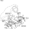
- Fig. 2 is a partial perspective view in the passenger compartment of the vehicle with the front seat and center console box removed.
- a passenger compartment 1 of a vehicle includes, at the front region of the vehicle, a dash board 31 in addition to a driver seat 11 and a front passenger seat 12 arranged as the front seat.
- Driver seat 11 and front passenger seat 12 are affixed to the floor 10 of the vehicle by means of seat legs 210 and 220. In general, these seat legs 210 and 220 are concealed by a foot cover not shown.
- a center console box 21 extending in the longitudinal direction of the vehicle is arranged between driver seat 11 and front passenger seat 12. The lower end region of center console box 21 at the rear side has an air introduction slit 22 to draw in air from the passenger compartment into center console box 21 as the air for cooling.
- the battery pack including a first battery pack 40 and a second battery pack 50 disposed above first battery pack 40.
- a junction box 60 is placed above second battery pack 50.
- a first cooling fan 70 is attached at the front side of first battery pack 40.
- First cooling fan 70 is connected to a first exhaust duct 90 extending towards the driver seat side.
- a second cooling fan 80 is attached at the front side of second battery pack 50.
- Second cooling fan 80 is connected to a second exhaust duct 100 extending towards the front passenger seat.
- Driver seat 11 is mounted on seat legs 210, 210 of substantially a salient and upward configuration, extending in the longitudinal direction of the vehicle. Driver seat 11 is supported to move in the fore-and-aft direction.
- One pair of seat legs 210 is provided, arranged with a predetermined distance therebetween in the lateral direction.
- Each seat leg 210 is formed of one guide rail 211 and two semicircular arc-shaped legs 212.
- front passenger seat 12 is mounted on seat legs 220, 220 of substantially a salient and upward configuration, extending in the longitudinal direction of the vehicle. Front passenger seat 12 is supported to move in the fore-and-aft direction.
- seat leg 220 is formed of one guide rail 221 and two semicircular arc-shaped legs 222.
- first exhaust duct 90 is disposed so as to traverse a space A1 defined by seat leg 210 and floor 10.
- Second exhaust duct 100 is disposed so as to traverse space A1 defined by seat leg 220 and floor 10.
- a DCDC converter 110 qualified as the target apparatus to be cooled is mounted on first exhaust duct 90 located at the driver seat 11 side.
- Audio equipment 120 is mounted on second exhaust duct 100 located at the front passenger seat 12 side.
- first cooling fan 70 and first exhaust duct 90 constitute the cooling apparatus for first battery pack 40.
- Second cooling fan 80 and second exhaust duct 100 constitute the cooling apparatus for second battery pack 50.
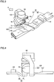
- Fig. 3 is a perspective view of extraction of battery packs, sirocco fans, and exhaust ducts.
- Fig. 4 is a view taken from the direction of arrow A in Fig. 3 .
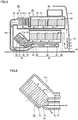
- Fig. 5 is a vertical sectional view of inside the center console box taken along the longitudinal direction of the vehicle.
- Fig. 6 is a partial enlarged sectional view of the attachment structure of first cooling fan 70.
- an air inlet 73 for first cooling fan 70 is connected to an air outlet 54 provided at the lower end side of first battery pack 40 at the front side of the vehicle.
- First exhaust duct 90 is connected to an air outlet 74 for first cooling fan 70.
- First exhaust duct 90 includes a first center exhaust duct 91 extending between driver seat 11 and front passenger seat 12 towards the rear side of the vehicle, and a first under seat exhaust duct 92 extending beneath driver seat 11 from first center exhaust duct 91.
- the exhaust outlet of first under seat exhaust duct 92 is connected to an exhaust duct arranged below driver seat 11 or below the door at the driver seat 11 side.
- Second exhaust duct 100 is connected to an air outlet 84 for second cooling fan 80.
- Second exhaust duct 100 includes a second center exhaust duct 100 extending downwards towards floor 10 and then towards the rear side between driver seat 11 and front passenger seat 12, and a second under seat exhaust duct 102 extending beneath front passenger seat 12 from second center exhaust duct 101.
- the exhaust outlet of second under seat exhaust duct 102 is connected to the exhaust duct arranged below front passenger seat 12, or below the door at the front passenger seat 12 side.
- the exhaust ducts from the battery packs are respectively disposed beneath driver seat 11 and beneath front passenger seat 12.
- the discharged cooling air output from first and second battery packs 40 and 50 can be split into two directions to be output into the passenger compartment.
- the airflow around the foot output from first and second under seat exhaust ducts 92 and 102 can be reduced to avoid discomfort caused by increase in local airflow and prevent degradation of the cabin environment.
- a sirocco fan 71 accommodated in a chamber 72 is employed for first cooling fan 70.
- a sirocco fan 81 accommodated in a chamber 82 is employed for second cooling fan 80.
- First cooling fan 70 and second cooling fan 80 have the same performance.
- the sirocco fan is an air blower that draws in air in the direction of the rotation shaft from the center of the rotating fan and discharges air in a direction crossing the rotational shaft.
- first cooling fan 70 provided for first battery pack 40 located at the lower side is attached in a manner similar to that of second cooling fan 80 located at the upper side, the exhaust duct must be bent extremely in a U shape so as to run towards the rear since there is no distance margin in height.
- bending the exhaust duct in a U shape is not preferable in view of resistance in air flow, i.e. pressure loss.
- air inlet 73 for first cooling fan 70 located at the lower side is disposed at the upper side
- air outlet 74 is disposed at the lower side in the present embodiment.
- first cooling fan 70 is arranged such that a direction R1 of the exhaust flow output from first cooling fan 70 crosses an extending direction H1 of first center exhaust duct 91 at an angle ⁇ larger than 90 degrees, as shown in Fig. 6 .
- second center exhaust duct 101 is free of an extreme bent since the distance in the direction of height can be ensured as a result of second cooling fan 80 arranged above first cooling fan 70. Further, since the distance can be ensured in the direction of the height for second center exhaust duct 101, the duct channel can be shifted towards the front passenger seat side, as shown in Fig. 4 .
- first center exhaust duct 91 extends straight to the rear side from air outlet 74 of first cooling fan 70, and is disposed between driver seat 11 and front passenger seat 12 at the driver seat side.
- Second center exhaust duct 101 is arranged to descend towards floor 10 while gradually deviating towards the front passenger seat side from air outlet 84 of second cooling fan 80, and to run between driver seat 11 and front passenger seat 12 at the front passenger seat side.
- first center exhaust duct 91 and second center exhaust duct 10 on floor 10 between driver seat 11 and front passenger seat 12 are located between the bottom face of first battery pack 70 and vehicle floor 10.
- Each of exhaust ducts 91 and 101 constitutes a heat insulation layer by virtue of the flow of cooling air therein, allowing the heat transfer from an exhaust pipe 2 (refer to Fig. 7 ) disposed beneath floor 10 to first battery pack 70 to be blocked. Therefore, power supply of first battery pack 7 can be stabilized.
- Fig. 7 is a vertical sectional view of the center console box taken along the transverse direction of the vehicle.
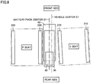
- Fig. 8 is a plan view schematically showing the positional relationship of the vehicle center position, the battery pack, and the driver seat.
- the driver seat is arranged directed to the inner side of the vehicle (approximately 1.5 degrees) for ensuring visual confirmation. Therefore, the position of the center D1 of the battery pack is located deviated to the front passenger seat side from the center C1 of the vehicle in order to ensure the space for moving driver seat 11 fore-and-aft.
- floor 10B between auxiliary beams 1A has a recess downwards from the standpoint of mounting first and second battery packs 40 and 50 on floor 10 between driver seat 11 and front passenger seat 12, and arranging first and second center exhaust ducts 91 and 101 between floor 10 and first battery pack 40.
- auxiliary beam 1A cannot be changed in position since it is a reinforcing member.
- DCDC converter 110 is placed at the first exhaust duct 90 side, extending in a direction opposite to the deviating direction of first and second battery packs 40 and 50 in the present embodiment.
- the first exhaust duct 90 side is advantageous in ensuring a large cross section of the passage, as will be described hereinafter.
- DCDC converter 110 qualified as the target apparatus to be cooled is mounted on first under seat exhaust duct 92 at the first exhaust duct 90 side, and a cooling fan 111 provided for DCDC converter 110 is arranged so as to protrude into the conduit of first under seat exhaust duct 92.
- DCDC converter 110 can be cooled efficiently at first under seat exhaust duct 92 that allows sufficient passage of the cooling air.
- the length of the exhaust duct can be set shorter than second exhaust duct 100 by virtue of arranging first battery pack 40 at the lower side. Accordingly, pressure loss is obviated to allow sufficient flow of cooling air.
- first cooling fan 70 and second cooling fan 80 connected to first exhaust duct 90 and second exhaust duct 100, respectively can be thought of as an approach to equalize the relative pressure loss at the exhaust ducts.
- using cooling fans of different capacity will render control complex, and differentiating the rotation between the cooling fan may cause the additional problem of noise. If is therefore desirable to operate the fans at low speed.
- a cooling fan of the same performance is used for first cooling fan 70 and second cooling fan 80 in the present embodiment.
- first and second battery packs 40 and 50 any other cooling structure may be employed such as an upper flow type cooling configuration, as long as the air flow is delivered in the battery pack from the rear side to the front side of the vehicle.
- first cooling fan 70 and second cooling fan 80 respectively, to exhibit the heat insulation effect for first battery pack 70, as set forth below.
- the air also cools DCDC converter 110 mounted on first under seat exhaust duct 92.
- the cooling air can be output from first under seat exhaust duct 92 and second under seat exhaust duct 100, split into two directions, into the passenger compartment. As a result, the airflow around the foot output from first and second under seat exhaust ducts 92 and 102 can be reduced to avoid discomfort caused by increase in local airflow and prevent degradation of the cabin environment, as set forth below.
- the battery pack of the present embodiment includes first battery pack 40 and second battery pack 50 disposed above first battery pack 40, and first battery pack 40 and second battery pack 50 are arranged such that the rear end of first battery pack 40 is located at the front side than the rear end of second battery pack 50. Accordingly, a space A2 is provided between the bottom of second battery pack 50 at the rear side and floor 10.
- junction box 60 is arranged on second battery pack 50.
- This junction box 60 is electrically connected to DCDC converter 110 placed on first under seat exhaust duct 92 by harness 130.
- harness 130 With regards to the wiring arrangement of harness 130, one end of harness 130 is led out from the trailing end side of junction box 60 and descends along the rear side of second battery pack 50 to be routed to space A2 formed between the bottom of second battery pack 50 at the rear side and floor 10. Then, harness 130 runs traversing space A1 defined by seat leg 210 and floor 10. Eventually, the other end of harness 130 is connected to DCDC converter 110.
- DCDC converter 110 is an example of an apparatus electrically connected to junction box 60 by harness 130.
- a wiring arrangement similar to that of harness 130 set forth above can be employed for an apparatus placed under driver seat 11 or front passenger seat 12.
- first and second battery packs 40 and 50 employed in a vehicle can be arranged efficiently in the space of the passenger compartment, and the distance between second battery pack 50 accommodated in center console box 21 and DCDC converter 110 arranged under driver seat 11 (or front passenger seat 12) can be shortened. Therefore, the length of the harness employed for electrical connection between second battery pack 50 and DCDC converter 110 can be reduced, and the workability in assembling the battery pack and peripheral apparatus can be rendered favorable.
- harness 130 must be routed vertically, harness 130 cannot be led directly breadthwise of the vehicle since seat rail 211 of seat leg 210 is located in the neighborhood of center console box 21. Further, the approach of routing harness 130 at the front side of second battery pack 50 is not preferable in view of harness 130 being damaged in the case of front-end collision.
- the arrangement of harness 130 in the present embodiment is advantageous in that harness 130 will not be damaged at the time of front-end collision since the arrangement of routing harness 130 downwards along the rear side of second battery pack 50 is employed. Further, the workability of assembling is facilitated by virtue of routing harness 130 to space A2.
- a battery pack of a structure having two stages of battery packs arranged vertically is employed in the embodiment set forth above, a similar functional advantage can be achieved by a battery pack having a configuration of one stage or a plurality of stages.
Landscapes
- Chemical & Material Sciences (AREA)
- Chemical Kinetics & Catalysis (AREA)
- Electrochemistry (AREA)
- General Chemical & Material Sciences (AREA)
- Engineering & Computer Science (AREA)
- Aviation & Aerospace Engineering (AREA)
- Arrangement Or Mounting Of Propulsion Units For Vehicles (AREA)
- Battery Mounting, Suspending (AREA)
Applications Claiming Priority (2)
| Application Number | Priority Date | Filing Date | Title |
|---|---|---|---|
| JP2005097296A JP4774783B2 (ja) | 2005-03-30 | 2005-03-30 | 駆動用電池パック搭載構造 |
| PCT/JP2006/305197 WO2006109402A1 (ja) | 2005-03-30 | 2006-03-09 | 電池パック搭載構造 |
Publications (3)
| Publication Number | Publication Date |
|---|---|
| EP1865567A1 EP1865567A1 (en) | 2007-12-12 |
| EP1865567A4 EP1865567A4 (en) | 2009-09-23 |
| EP1865567B1 true EP1865567B1 (en) | 2018-06-27 |
Family
ID=37086693
Family Applications (1)
| Application Number | Title | Priority Date | Filing Date |
|---|---|---|---|
| EP06715688.5A Ceased EP1865567B1 (en) | 2005-03-30 | 2006-03-09 | Battery pack mounting structure |
Country Status (5)
| Country | Link |
|---|---|
| US (1) | US7819215B2 (enExample) |
| EP (1) | EP1865567B1 (enExample) |
| JP (1) | JP4774783B2 (enExample) |
| CN (1) | CN101151743B (enExample) |
| WO (1) | WO2006109402A1 (enExample) |
Families Citing this family (38)
| Publication number | Priority date | Publication date | Assignee | Title |
|---|---|---|---|---|
| JP4363350B2 (ja) * | 2005-03-30 | 2009-11-11 | トヨタ自動車株式会社 | 二次電池の冷却構造 |
| JP4940749B2 (ja) * | 2006-04-28 | 2012-05-30 | トヨタ自動車株式会社 | 電源装置の車両搭載構造 |
| JP4857896B2 (ja) * | 2006-05-11 | 2012-01-18 | トヨタ自動車株式会社 | 組電池および車両 |
| DE102006039106A1 (de) * | 2006-08-19 | 2008-02-21 | Daimler Ag | Vorrichtung zum Antreiben eines Brennstoffzellen-Fahrzeuges |
| JP2008114706A (ja) * | 2006-11-02 | 2008-05-22 | Toyota Motor Corp | 蓄電装置および自動車 |
| JP5173182B2 (ja) * | 2006-11-13 | 2013-03-27 | トヨタ自動車株式会社 | 蓄電装置ユニット |
| JP4390802B2 (ja) * | 2006-12-15 | 2009-12-24 | トヨタ自動車株式会社 | 車載バッテリ冷却構造 |
| JP4858203B2 (ja) * | 2007-02-07 | 2012-01-18 | トヨタ自動車株式会社 | 自動車 |
| KR20090062380A (ko) * | 2007-12-13 | 2009-06-17 | 현대자동차주식회사 | 하이브리드 배터리시스템의 출구덕트 |
| FR2934525B1 (fr) * | 2008-07-31 | 2010-08-20 | Peugeot Citroen Automobiles Sa | Dispositif de stockage et de fourniture d'energie pour vehicule automobile |
| DE102008051085A1 (de) * | 2008-10-09 | 2010-04-15 | Dr.Ing.H.C.F.Porsche Aktiengesellschaft | Batterieanordnung |
| DE102009058996B4 (de) * | 2008-12-21 | 2012-12-06 | W.E.T. Automotive Systems Ag | Belüftungseinrichtung |
| JP5040905B2 (ja) * | 2008-12-24 | 2012-10-03 | トヨタ自動車株式会社 | 蓄電装置の温度調節構造 |
| DE112010003092T5 (de) * | 2009-07-27 | 2012-05-31 | Honda Motor Co., Ltd. | Montagestruktur für elektrische Fahrzeugeinrichtung |
| FR2972143B1 (fr) * | 2011-03-01 | 2013-09-20 | Renault Sa | Systeme de liaison d'une batterie d'alimentation d'un vehicule automobile |
| WO2012150629A1 (ja) * | 2011-05-02 | 2012-11-08 | トヨタ自動車株式会社 | 燃料電池車両 |
| JP5652719B2 (ja) * | 2011-05-02 | 2015-01-14 | スズキ株式会社 | 燃料電池車両 |
| KR101252211B1 (ko) * | 2011-09-26 | 2013-04-05 | 기아자동차주식회사 | 차량용 고전압 배터리팩 장치 |
| US9187052B2 (en) * | 2011-11-16 | 2015-11-17 | Toyota Jidosha Kabushiki Kaisha | Vehicle |
| JP5906689B2 (ja) * | 2011-11-22 | 2016-04-20 | トヨタ自動車株式会社 | 車両用電池搭載構造 |
| KR101316432B1 (ko) * | 2011-12-01 | 2013-10-08 | 기아자동차주식회사 | 차량의 배터리팩 탑재 구조 |
| JP5459348B2 (ja) * | 2012-05-09 | 2014-04-02 | トヨタ自動車株式会社 | 蓄電装置ユニット |
| JP5983054B2 (ja) * | 2012-06-04 | 2016-08-31 | スズキ株式会社 | ハイブリッド自動車のバッテリパック冷却構造 |
| JP5870457B2 (ja) * | 2012-11-08 | 2016-03-01 | 本田技研工業株式会社 | 電動車両 |
| JP5986224B2 (ja) * | 2012-12-25 | 2016-09-06 | 川崎重工業株式会社 | 電動車両 |
| US9440509B2 (en) * | 2013-10-04 | 2016-09-13 | Ford Global Technologies, Llc | Battery cooling apparatus |
| CN107074086B (zh) * | 2014-10-27 | 2019-05-07 | 本田技研工业株式会社 | 车辆 |
| WO2016072286A1 (ja) * | 2014-11-07 | 2016-05-12 | 本田技研工業株式会社 | 車両 |
| JP6310951B2 (ja) * | 2016-01-27 | 2018-04-11 | 株式会社豊田自動織機 | 車両 |
| JP6471738B2 (ja) * | 2016-11-17 | 2019-02-20 | トヨタ自動車株式会社 | 車両下部構造 |
| CN106953045A (zh) * | 2017-04-21 | 2017-07-14 | 阿尔特汽车技术股份有限公司 | Phev电池包冷却结构 |
| JP6541724B2 (ja) * | 2017-07-10 | 2019-07-10 | 株式会社Subaru | 自動車車両 |
| CN109835218A (zh) * | 2017-11-24 | 2019-06-04 | 宁波比亚迪汽车有限公司 | 动力电池系统布置结构及一种新能源汽车 |
| DE102018206386A1 (de) | 2018-04-25 | 2019-10-31 | Bayerische Motoren Werke Aktiengesellschaft | Fahrzeug mit erweiterter Belüftung |
| JP7775762B2 (ja) * | 2022-03-25 | 2025-11-26 | スズキ株式会社 | 電動ユニット |
| US12377786B2 (en) | 2022-11-02 | 2025-08-05 | Nissan North America, Inc. | Center console assembly |
| US12119465B2 (en) * | 2022-11-14 | 2024-10-15 | Archer Aviation Inc. | Heat exchanger assemblies and cooling systems for evtol aircraft |
| US20240421407A1 (en) * | 2023-06-15 | 2024-12-19 | GM Global Technology Operations LLC | Cell stack support for a vehicle battery cell |
Family Cites Families (28)
| Publication number | Priority date | Publication date | Assignee | Title |
|---|---|---|---|---|
| US5639571A (en) * | 1996-06-24 | 1997-06-17 | General Motors Corporation | Battery pack |
| US5736272A (en) * | 1997-01-21 | 1998-04-07 | Ford Global Technologies, Inc. | Battery tray |
| JP3330049B2 (ja) * | 1997-03-07 | 2002-09-30 | 本田技研工業株式会社 | 電気自動車の制御装置 |
| US5882213A (en) * | 1997-10-03 | 1999-03-16 | Ut Automotive Dearborn, Inc. | Battery mounted junction box |
| JP2001105893A (ja) | 1999-10-07 | 2001-04-17 | Suzuki Motor Corp | 電気自動車 |
| JP3777981B2 (ja) * | 2000-04-13 | 2006-05-24 | トヨタ自動車株式会社 | 車両用電源装置 |
| JP2002219949A (ja) | 2001-01-26 | 2002-08-06 | Toyota Motor Corp | 車両用電源装置 |
| US6632560B1 (en) * | 2001-01-29 | 2003-10-14 | Shijian Zhou | Retention frame for a battery pack |
| US6811197B1 (en) * | 2002-11-14 | 2004-11-02 | Ford Global Technologies, Llc | Housing assembly for electrical energy storage device |
| JP4078998B2 (ja) | 2003-02-04 | 2008-04-23 | トヨタ自動車株式会社 | 車両用バッテリ搭載構造 |
| JP4178986B2 (ja) * | 2003-02-13 | 2008-11-12 | トヨタ自動車株式会社 | 車両用電気機器の搭載構造 |
| JP3861826B2 (ja) | 2003-02-24 | 2006-12-27 | トヨタ車体株式会社 | 車両のフロントシート |
| JP4050168B2 (ja) * | 2003-03-10 | 2008-02-20 | トヨタ自動車株式会社 | 自動車 |
| JP4489369B2 (ja) | 2003-03-26 | 2010-06-23 | パナソニックEvエナジー株式会社 | 電池パック |
| JP2004291715A (ja) | 2003-03-26 | 2004-10-21 | Toyota Motor Corp | 自動車 |
| JP2004291757A (ja) * | 2003-03-26 | 2004-10-21 | Nissan Diesel Motor Co Ltd | バス室内の床構造 |
| US6935449B2 (en) * | 2003-04-02 | 2005-08-30 | General Motors Corporation | Vehicle electrical distribution system and method of use therefor |
| JP4637504B2 (ja) | 2003-05-21 | 2011-02-23 | 本田技研工業株式会社 | 高圧電装ケースの配設構造 |
| US7048321B2 (en) * | 2003-05-21 | 2006-05-23 | Honda Motor Co., Ltd. | High-voltage electrical equipment case arranging structure |
| JP4121898B2 (ja) * | 2003-05-21 | 2008-07-23 | 本田技研工業株式会社 | 高圧電装部品の車載構造 |
| DE112004002247B8 (de) * | 2003-11-28 | 2014-04-03 | Toyota Jidosha Kabushiki Kaisha | Befestigungsstruktur für ein Fahrzeugbatteriepaket |
| JP4503345B2 (ja) | 2004-04-22 | 2010-07-14 | 本田技研工業株式会社 | 車両のバッテリ又は高圧電装部品の冷却構造 |
| JP4687015B2 (ja) * | 2004-06-23 | 2011-05-25 | トヨタ自動車株式会社 | 電源装置 |
| US7353900B2 (en) * | 2004-09-21 | 2008-04-08 | Nissan Motor Co., Ltd. | Battery cooling system |
| JP4415910B2 (ja) * | 2005-07-12 | 2010-02-17 | トヨタ自動車株式会社 | ハイブリッド車両の構造 |
| JP4940749B2 (ja) * | 2006-04-28 | 2012-05-30 | トヨタ自動車株式会社 | 電源装置の車両搭載構造 |
| JP4337905B2 (ja) * | 2007-04-18 | 2009-09-30 | トヨタ自動車株式会社 | 車両に搭載された電気機器の冷却装置 |
| US7419209B1 (en) * | 2007-05-30 | 2008-09-02 | Lear Corporation | Seat assembly providing airflow path to cool batteries |
-
2005
- 2005-03-30 JP JP2005097296A patent/JP4774783B2/ja not_active Expired - Fee Related
-
2006
- 2006-03-09 WO PCT/JP2006/305197 patent/WO2006109402A1/ja not_active Ceased
- 2006-03-09 CN CN200680010600XA patent/CN101151743B/zh not_active Expired - Fee Related
- 2006-03-09 US US11/794,902 patent/US7819215B2/en not_active Expired - Fee Related
- 2006-03-09 EP EP06715688.5A patent/EP1865567B1/en not_active Ceased
Non-Patent Citations (1)
| Title |
|---|
| None * |
Also Published As
| Publication number | Publication date |
|---|---|
| JP2006278201A (ja) | 2006-10-12 |
| US7819215B2 (en) | 2010-10-26 |
| JP4774783B2 (ja) | 2011-09-14 |
| US20080047767A1 (en) | 2008-02-28 |
| CN101151743B (zh) | 2011-07-06 |
| EP1865567A4 (en) | 2009-09-23 |
| EP1865567A1 (en) | 2007-12-12 |
| CN101151743A (zh) | 2008-03-26 |
| WO2006109402A1 (ja) | 2006-10-19 |
Similar Documents
| Publication | Publication Date | Title |
|---|---|---|
| EP1865567B1 (en) | Battery pack mounting structure | |
| EP1864844B1 (en) | Cooling structure of secondary battery | |
| EP1864845B1 (en) | Cooling structure for secondary battery | |
| CN103318007B (zh) | 汽车 | |
| US9012056B2 (en) | High voltage battery pack apparatus for vehicle | |
| US20100231035A1 (en) | Power supply apparatus | |
| US20100071980A1 (en) | Electric power storage apparatus and car | |
| WO2008072782A1 (ja) | 車載バッテリ冷却構造 | |
| CN104024012B (zh) | 车辆 | |
| JP2017077790A (ja) | 車両 | |
| JP4023450B2 (ja) | 電気機器の冷却装置 | |
| US11824179B2 (en) | Power supply device | |
| JP4363391B2 (ja) | 電気部品の取り付け構造 | |
| JP2018190517A (ja) | 車載用バッテリー | |
| JP2021027010A (ja) | 車両用バッテリパック | |
| WO2025163795A1 (ja) | 電池搭載構造 | |
| JP2024175993A (ja) | 車両用外気取入構造 |
Legal Events
| Date | Code | Title | Description |
|---|---|---|---|
| PUAI | Public reference made under article 153(3) epc to a published international application that has entered the european phase |
Free format text: ORIGINAL CODE: 0009012 |
|
| 17P | Request for examination filed |
Effective date: 20070717 |
|
| AK | Designated contracting states |
Kind code of ref document: A1 Designated state(s): DE FR GB |
|
| DAX | Request for extension of the european patent (deleted) | ||
| RBV | Designated contracting states (corrected) |
Designated state(s): DE FR GB |
|
| A4 | Supplementary search report drawn up and despatched |
Effective date: 20090825 |
|
| RAP1 | Party data changed (applicant data changed or rights of an application transferred) |
Owner name: TOYOTA JIDOSHA KABUSHIKI KAISHA |
|
| 17Q | First examination report despatched |
Effective date: 20140312 |
|
| RIC1 | Information provided on ipc code assigned before grant |
Ipc: B60K 1/00 20060101ALN20171221BHEP Ipc: B60K 1/04 20060101ALI20171221BHEP Ipc: H01M 10/613 20140101ALI20171221BHEP Ipc: H01M 10/658 20140101ALI20171221BHEP Ipc: H01M 2/10 20060101AFI20171221BHEP Ipc: H01M 10/667 20140101ALI20171221BHEP Ipc: H01M 10/6563 20140101ALI20171221BHEP Ipc: B60K 11/06 20060101ALI20171221BHEP Ipc: H01M 10/625 20140101ALI20171221BHEP Ipc: H01M 6/42 20060101ALN20171221BHEP |
|
| GRAP | Despatch of communication of intention to grant a patent |
Free format text: ORIGINAL CODE: EPIDOSNIGR1 |
|
| INTG | Intention to grant announced |
Effective date: 20180201 |
|
| RIC1 | Information provided on ipc code assigned before grant |
Ipc: H01M 2/10 20060101AFI20180119BHEP Ipc: H01M 10/625 20140101ALN20180119BHEP Ipc: H01M 10/613 20140101ALN20180119BHEP Ipc: H01M 10/6563 20140101ALN20180119BHEP Ipc: B60K 11/06 20060101ALI20180119BHEP Ipc: B60K 1/00 20060101ALN20180119BHEP Ipc: B60K 1/04 20060101ALI20180119BHEP |
|
| RIN1 | Information on inventor provided before grant (corrected) |
Inventor name: TSUCHIYA, TAKENORI |
|
| GRAS | Grant fee paid |
Free format text: ORIGINAL CODE: EPIDOSNIGR3 |
|
| GRAA | (expected) grant |
Free format text: ORIGINAL CODE: 0009210 |
|
| AK | Designated contracting states |
Kind code of ref document: B1 Designated state(s): DE FR GB |
|
| REG | Reference to a national code |
Ref country code: GB Ref legal event code: FG4D |
|
| REG | Reference to a national code |
Ref country code: DE Ref legal event code: R096 Ref document number: 602006055691 Country of ref document: DE |
|
| REG | Reference to a national code |
Ref country code: DE Ref legal event code: R084 Ref document number: 602006055691 Country of ref document: DE |
|
| REG | Reference to a national code |
Ref country code: GB Ref legal event code: 746 Effective date: 20181122 |
|
| REG | Reference to a national code |
Ref country code: DE Ref legal event code: R097 Ref document number: 602006055691 Country of ref document: DE |
|
| PLBE | No opposition filed within time limit |
Free format text: ORIGINAL CODE: 0009261 |
|
| STAA | Information on the status of an ep patent application or granted ep patent |
Free format text: STATUS: NO OPPOSITION FILED WITHIN TIME LIMIT |
|
| 26N | No opposition filed |
Effective date: 20190328 |
|
| REG | Reference to a national code |
Ref country code: DE Ref legal event code: R079 Ref document number: 602006055691 Country of ref document: DE Free format text: PREVIOUS MAIN CLASS: H01M0002100000 Ipc: H01M0050200000 |
|
| PGFP | Annual fee paid to national office [announced via postgrant information from national office to epo] |
Ref country code: FR Payment date: 20210210 Year of fee payment: 16 |
|
| PGFP | Annual fee paid to national office [announced via postgrant information from national office to epo] |
Ref country code: DE Payment date: 20210224 Year of fee payment: 16 Ref country code: GB Payment date: 20210225 Year of fee payment: 16 |
|
| REG | Reference to a national code |
Ref country code: DE Ref legal event code: R119 Ref document number: 602006055691 Country of ref document: DE |
|
| GBPC | Gb: european patent ceased through non-payment of renewal fee |
Effective date: 20220309 |
|
| PG25 | Lapsed in a contracting state [announced via postgrant information from national office to epo] |
Ref country code: GB Free format text: LAPSE BECAUSE OF NON-PAYMENT OF DUE FEES Effective date: 20220309 Ref country code: FR Free format text: LAPSE BECAUSE OF NON-PAYMENT OF DUE FEES Effective date: 20220331 Ref country code: DE Free format text: LAPSE BECAUSE OF NON-PAYMENT OF DUE FEES Effective date: 20221001 |