EP1862139A2 - Appareil de thérapie - Google Patents
Appareil de thérapie Download PDFInfo
- Publication number
- EP1862139A2 EP1862139A2 EP07075546A EP07075546A EP1862139A2 EP 1862139 A2 EP1862139 A2 EP 1862139A2 EP 07075546 A EP07075546 A EP 07075546A EP 07075546 A EP07075546 A EP 07075546A EP 1862139 A2 EP1862139 A2 EP 1862139A2
- Authority
- EP
- European Patent Office
- Prior art keywords
- shaft
- trocar
- arrangement according
- application arrangement
- electrode needle
- Prior art date
- Legal status (The legal status is an assumption and is not a legal conclusion. Google has not performed a legal analysis and makes no representation as to the accuracy of the status listed.)
- Withdrawn
Links
Images


Classifications
-
- A—HUMAN NECESSITIES
- A61—MEDICAL OR VETERINARY SCIENCE; HYGIENE
- A61N—ELECTROTHERAPY; MAGNETOTHERAPY; RADIATION THERAPY; ULTRASOUND THERAPY
- A61N1/00—Electrotherapy; Circuits therefor
- A61N1/02—Details
- A61N1/04—Electrodes
- A61N1/06—Electrodes for high-frequency therapy
-
- A—HUMAN NECESSITIES
- A61—MEDICAL OR VETERINARY SCIENCE; HYGIENE
- A61B—DIAGNOSIS; SURGERY; IDENTIFICATION
- A61B18/00—Surgical instruments, devices or methods for transferring non-mechanical forms of energy to or from the body
- A61B18/04—Surgical instruments, devices or methods for transferring non-mechanical forms of energy to or from the body by heating
- A61B18/12—Surgical instruments, devices or methods for transferring non-mechanical forms of energy to or from the body by heating by passing a current through the tissue to be heated, e.g. high-frequency current
- A61B18/14—Probes or electrodes therefor
- A61B18/1477—Needle-like probes
-
- A—HUMAN NECESSITIES
- A61—MEDICAL OR VETERINARY SCIENCE; HYGIENE
- A61B—DIAGNOSIS; SURGERY; IDENTIFICATION
- A61B2218/00—Details of surgical instruments, devices or methods for transferring non-mechanical forms of energy to or from the body
- A61B2218/001—Details of surgical instruments, devices or methods for transferring non-mechanical forms of energy to or from the body having means for irrigation and/or aspiration of substances to and/or from the surgical site
- A61B2218/002—Irrigation
Definitions
- the invention relates to a therapy device, in particular an application arrangement for applying a high-frequency current for thermal obliteration of body tissue.
- the electrosurgical, especially the electrothermal sclerosing of pathologically altered body tissue is a known method in medicine. Of particular interest is this method for the therapy of organ tumors, eg. B. liver tumors.
- organ tumors eg. B. liver tumors.
- one or more electrodes are placed in the tissue to be sclerosed, ie the tumor tissue, or in its immediate vicinity, and an alternating current can flow between the electrodes or an electrode and a so-called neutral electrode fixed on the outside of the body. If the current flows between the electrode and the neutral electrode (possibly also between several electrodes and one or more neutral electrodes), then this is referred to as a monopolar electrode arrangement. In contrast, the current flows between those in the tissue located electrodes themselves (in this case, at least two electrodes must be introduced into the tissue), so it is called a bipolar arrangement.
- a current flow is induced by means of a high-frequency generator between the so-called active electrodes, which are in electrically conductive contact with the body tissue, and, for example, a neutral electrode.
- the electrical resistance of the body tissue leads to the fact that the alternating current is converted into heat.
- temperatures between 50 ° C and 100 ° C there is a massive denaturation of the body's own proteins and, as a result, the death of the affected tissue areas. Due to the high current density in the region of the active electrodes, the heating of the tissue takes place predominantly where the active electrodes are in electrically conductive contact with the body tissue.
- the intended for placement in the tissue electrode is usually arranged on an electrode needle.
- An electrode needle is for example in US 2002/0035363 described.
- the electrode needle described therein comprises an electrically conductive shaft and an insulating jacket axially displaceable relative to the shaft. By displacing the insulating jacket, the active surface, ie the surface of the shaft to be brought into contact with the body tissue for application of the electrode needle, can be determined.
- the US 2002/0035363 also describes a trocar through which the electrode needle is insertable into body tissue.
- a trocar is a body of the body with one intended for insertion into body tissue and one for Farther away from the body tissue section and a free lumen for insertion of instruments or for introducing or discharging liquids. It is used, for example, to empty liquids from body cavities or to introduce drugs specifically into specific body regions.
- the object of the invention is to provide an alternative application arrangement with a shank and an axially displaceable against the shank enveloping body, which has a simple structure and which can be used flexibly.
- the application arrangement according to claim 1 is characterized in that a counterelectrode is arranged on the outside of the insulating enveloping body.
- the term "counterelectrode” should be understood to mean any electrode which enables the bipolar operation of the application device.
- the shank and the counterelectrode are designed to be electrically independent of one another, ie electric potentials, in particular electrical potentials generated by a high-frequency generator, can be applied to them independently of each other, so that a high-frequency current flows between them.
- Such an electrode needle can be operated both bipolar and monopolar.
- the displaceability of the enveloping body makes it possible to influence the flow of current through the body tissue to be treated, by varying the length of the shank body projecting shank portion of the electrode needle - and thus the as electrode with the body tissue in electrically conductive contact bringable effective shaft surface.
- the described counterelectrode can also be used when the enveloping body is formed by a trocar. It is then located on the section of the trocar for introduction into body tissue.
- the trocar then has its own electrical connection for connecting a high-frequency generator to the counter electrode.
- the electrical connection can be designed as a plug contact, to which a counterpart exists on a part of the electrode needle not intended to be introduced into the body tissue, so that the trocar is to be connected to the high-frequency generator via the electrode needle. It is particularly user-friendly if the plug-in contact and the counterpart are arranged and configured in such a way that the connection of the plug-in contact with the counterpart is independent when the electrode needle is inserted into the trocar.
- the application arrangement according to claim 1 is characterized in that the section of the trocar intended to be introduced into body tissue is designed to be electrically insulating and forms the covering body for the shaft of the electrode needle, in particular when the electrode needle is passed through the lumen.
- the trocar fulfills two functions. On the one hand, it fulfills the traditional tasks of a trocar, namely, for example, to enable accurate drug delivery or tissue removal as well as the insertion of electrode needles, without having to be re-dotted every time.
- the part of the trocar located in the body serves as an insulating enveloping body displaceable relative to the shaft of the electrode needle Adjusting the length of the active region of the shaft, ie that region which protrudes from the insulating enveloping body and is in electrically conductive contact with the body tissue when the electrode needle is introduced into the body.
- Such an application arrangement has a simplified construction compared with the prior art in which, in addition to the trocar, there is a displaceable insulating sleeve around the shaft of the electrode needle.
- the length of the active region of electrode needles, which are not equipped with its own insulating sheath, adjustable is adjustable.
- the trocar forms the enveloping body of the electrode needle and therefore does not require its own enveloping body, the overall diameter of the portion of the trocar intended for introduction into the body tissue can be kept small.
- the puncturing with the application arrangement according to the invention is therefore less traumatic than with the trocar-needle combination according to the prior art.
- a displacement device for example. Using a guide element, is provided, with which the length of the protruding from the distal end of the envelope body part of the shaft can be adjusted.
- the displacement device may in particular comprise a clamping or screwing mechanism for locking the electrode needle relative to the enveloping body, in order to counteract undesired displacement of the enveloping body relative to the electrode needle.
- a particularly precise adjustment of the length of the protruding from the distal end of the envelope part of the shaft can be achieved that the application arrangement on the electrode needle, in particular at the proximal end of the shaft, a guide member and the axial displacement of the enveloping body relative to the shaft an inner - And external thread combination on the trocar and the guide element is present.
- the inner and outer thread combination makes it possible, by turning the guide element relative to the trocar, to move the enveloping body relative to the shaft precisely.
- the electrode needle or the trocar in particular the clamping or screwing mechanism, may include markers that make up the length of protruding from the distal end of the envelope body of the shaft when removed inserted in the body shaft. The markings allow the targeted setting of the active length of the electrode, even when introduced into the body electrode needle.
- the enveloping body is characterized in that it engages tightly around the shaft.
- the tight enclosure prevents body fluid from penetrating between the shaft and the sheath. Penetrating bodily fluids, as a conductive fluid, could cause not only the sheath-protruding and therefore uncovered portion of the shaft to be in electrically conductive communication with the body tissue, but also portions of the shaft that should actually be electrically isolated from the body tissue.
- a gap is present between the shaft and the inside of the enveloping body.
- the portion of the trocar which is intended to remain outside the body may have a fluid supply for supplying fluids into the gap.
- the gap makes it possible, when the electrode needle is inserted, to introduce fluids, in particular liquids, into the target area of the body tissue.
- Fluids that can be introduced into the target area include, for example, medicines, analgesics, rinsing agents or liquids which counteract the drying out of the tissue during the application of the high-frequency current and thus considerably increase the efficiency of the thermal destruction.
- the liquids are preferably electrical conductive to maintain electrical contact of the shaft with the body tissue.
- electrically conductive liquids are z. B. physiological saline.
- the dimension of the gap may advantageously be chosen such that a certain liquid pressure must be exceeded so that the liquid can flow through the gap. This configuration makes it possible to prevent electrically conductive body fluids from penetrating into the gap and thus to produce an electrically conductive connection between the body tissue and parts of the shaft which should actually be insulated from the body tissue by the enveloping body.
- a further embodiment of the invention is characterized in that the shaft is provided with a tip at its distal end.
- the tip which protrudes from the distal end of the enveloping body when the sheath is introduced into the sheath body, can serve as puncture means when the trocar is inserted into the body tissue, so that the electrode needle can be used as an insertion aid for the trocar.
- the enveloping body can at its distal end a phase, i. have a tapered portion, so that no gradual transition between the enveloping body and the shaft is present.
- the portion of the trocar intended for introduction into body tissue comprises a material which makes it visible in a computed tomography or nuclear spin tomographic image, so that the seat of the trocar can be checked by means of computed tomography or magnetic resonance tomography.
- a material may be, for example, gold.
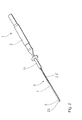
- FIG. 1 shows an exemplary embodiment of the application arrangement according to the invention in a perspective view.
- the application arrangement comprises an electrode needle 1 with a handle portion 2 for handling the electrode needle 1 and a shaft 3 made of an electrically conductive material, which can be connected to a high-frequency generator, not shown. It further comprises a trocar 5 having a portion 7 adapted to be inserted into body tissue and a portion 11 formed to remain outside the body tissue.
- the trocar 5 has a lumen 13 (see FIG. 3) through which the electrode needle 1 is to be inserted such the shaft 3 of the electrode needle 1 extends through the section 7 of the trocar 5.
- the section 7 tightly encloses the shaft 3 of the electrode needle 1. It consists of an insulating material, so that it forms an insulating enveloping body for the shaft 3 of the electrode needle 1.
- the displacement device comprises a cylindrical guide element 15 in the exemplary embodiment illustrated in FIG. 3, the electrode needle 1 introduced through the lumen 13 of the trocar 5 can be displaced axially relative to the trocar 5.
- the displacement device comprises markings which, in the present exemplary embodiment, are designed as annular grooves 19 extending around the circumference of the guide element 15.
- clamping mechanism 17 in the form of a trained for engaging in the annular grooves 19 ball.
- the ball 17 is pressed by a prestressed compression spring 18 against the peripheral surface of the displacement device and can engage in the annular grooves 19, so as to secure the displacement device against accidental axial displacement.
- the annular grooves 19 other locking means can be used, provided they allow a latching of the ball 17.
- the length of the the envelope body 7 projecting distal portion of the electrically conductive shaft 3 vary.
- the section of the shaft 3 projecting from the distal end of the enveloping body 7 forms the active electrode of the electrode needle 1, ie the active electrode in contact with the body tissue after insertion into the body tissue.
- a high frequency generator by the high voltage to the active electrode can be applied.
- a counter electrode is applied, so that between the shaft 3 and the counter electrode a high-frequency current can flow, which leads to the destruction of the body tissue, for example, a tumor tissue.
- the shape and size of the destruction zone can be varied by the length of the protruding from the distal end of the envelope 7 section of the shaft 3.
- the shaft 3 of the electrode needle 1 can also be used to insert the trocar 5 into the body tissue.
- the shaft 3 has at its distal end a tip 23 for puncturing the body tissue.
- the trocar 5 can remain in the body tissue, in which case only the electrode needle 1 is pulled out of the trocar 5. He can then, for example, to be used for the introduction of drugs.
- the enveloping body 7 prevents carryover of tumor cells when pulling out the electrode needle.
- a fibrin adhesive can be introduced into the penetration channel during withdrawal in order to seal it.
- the application arrangement comprises a further, second electrode 25, which serves as counter electrode to the shaft electrode formed by the shaft 3. It is arranged on the outer circumference of the electrically insulating enveloping body 7.
- the axial length of the counter electrode 25 is about 1-20 times the diameter of the shaft 3.
- the enveloping body 7 extends around the entire circumference of the enveloping body 7 around an insulating portion 27 which isolates the counter electrode 25 from the shaft 3 and determines the distance of the counter electrode 25 of the shaft electrode.
- the counter electrode 25 has a separate from the shaft 3, extending through the jacket of the portion 11 of the trocar 5 electrical lead 29, via the ball 17, in the present embodiment, an electrically conductive ball, such as a metal ball, and the compression spring 18 with a connection 31 is connected for connecting a high-frequency generator. With this embodiment, the bipolar operation of the application arrangement is possible.
- the envelope 7 may also be formed as part of the electrode needle 1, wherein the envelope 7 is further designed to be displaceable against the shaft 3.
- An electrode needle designed in this way can also be used without a trocar. The presence of a trocar is therefore not necessary for varying the length of the protruding from the jacket 7 part of the shaft 3.
- FIGS. 4 and 5 represent a cross section through the enveloping body 7 and the shaft 3 introduced into the lumen of the enveloping body 7.
- an annular gap 21 extends between the inner wall of the enveloping body 7 and the outer surface of the shaft 3, through which, for example, a rinsing fluid can be introduced into the tissue to be treated.
- this gap makes it possible for 21 gases emerging from the treatment to escape from the body.
- FIG. An alternative embodiment is shown in FIG. Instead of a gap which extends around the entire circumference of the shaft 3, in this embodiment, four gaps 21 ', which each extend over only a part of the circumference of the shaft 3, are formed. They are formed as notches extending in the axial direction on the inner surface of the enveloping body 7 and extend over its entire length. Of course, the number of notches may be greater or less than four. The scores must be too have no quadrangular cross-section but may for example also have a triangular or round cross-section.
- FIG. 5 makes it possible for the enveloping body 7 to tightly surround the shaft 3 and thus counteract displacement of the shaft against the enveloping body 7 by its friction.
- the body to be treated in the body through the column 21 'liquids are supplied.
- gases that escape during treatment can escape.
- the dimensions of the notches 21 ' are preferably selected so that a predetermined fluid pressure must be exceeded in order for the fluid to flow through the notches 21'.
- Body fluids which are mostly electrically conductive, then can not easily penetrate into the notches 21 '.
- the trocar may have a phase for a syringe port at its portion 11 which is intended to remain outside the body.
- the trocar may also have a lateral fluid supply.
- the electrode needle 1 and / or the section 11 of the trocar which is intended to remain outside the body can also be provided with markings which show the user how far the shaft 3 protrudes from the enveloping body 7. This is particularly important if the application arrangement is already arranged in the body, so that the user has no visual contact with the distal end of the enveloping body 7. As such markings, for example, arranged on the guide member 15 annular grooves 19, colored markers or a combination of both serve.
- the enveloping body 7 may also have at its distal end a phase which is not shown in the figures.
- the trocar 5 may also be sealed in an alternative embodiment against leakage of gases and body fluids.
- the seal can be arranged as an annular seal on the inner circumference of the portion 11 to be retained outside the body and be designed such that it can engage in the annular grooves 19 of the guide element 15, so that the seal at the same time as a locking element for locking the electrode needle in a axial position relative to the trocar is to use.
- the seal may alternatively be arranged on the guide element, wherein the annular grooves are then arranged on the inner surface of the section 11.
- the trocar 5 and / or the handle portion 2 of the electrode needle 1 have a corrugation.
- the trocar can have a plurality of axially parallel sections, which are provided for insertion into body tissue, as enveloping bodies.
- the enveloping bodies each have a lumen which opens into a common lumen in the portion of the trocar intended to remain outside the body.
- Such a trocar introduces electrode needles with several shafts into the body tissue.
- the enveloping bodies are displaceable separately from one another against the respective shaft extending through them.
- a displacement device for moving the enveloping body relative to the shaft of the electrode needle having detent positions
- a displacement device may be provided with a stepless displacement and locking of the envelope allow relative to the shaft leaves.
- the enveloping body can be securely fixed to each other on the shaft in each relative position.
- a first treatment configuration using the application arrangement according to the invention is shown schematically in FIG.
- An operating in bipolar mode electrode needle 1 is inserted through an introduced into the body tissue of a patient 100 Trokar 5 in a region of the body to be sclerosed and connected via two lines 115 to a high-frequency generator 110.
- the high-frequency generator 110 provides the necessary for the electrothermal scoring high-frequency current flowing through a cable 115, the electrode needle 1 and the body tissue comprehensive circuit.
- the high frequency current flows between the electrodes of the electrode needle 1 through the body tissue to be sclerosed.
- FIG. 1 A second treatment configuration using the application arrangement according to the invention is shown schematically in FIG.
- An operated in monopolar mode electrode needle 1 is inserted through an introduced into the body tissue of a patient 100 trocar 5 in a region of the body to be sclerosed and connected via a line 115 to a high-frequency generator 110.
- a neutral electrode 120 also connected to the high frequency generator 110 via a line 116 is attached to the outside of the body of the patient 100.
- the high-frequency generator 110 provides the high-frequency current necessary for the electrothermal soiling, which flows through a circuit comprising the cable 115, the cable 116, the electrode needle 1, the neutral electrode 120 and the body tissue. The high-frequency current flows between the electrode needle 1 and the neutral electrode through the body tissue to be sclerosed.
- volume treatment is used to treat pathogenic tumor tissue, especially in internal organs.
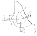
- Figures 8A, B and C show schematically a portion of the body tissue 100 of a patient and a tumor tissue 102 therein.
- a number of trocars 5 are inserted into the patient's body such that the distal ends thereof are for insertion
- an electrode needle 1 with a tip 23 is inserted into the trocar 5 at the distal end of its shaft 3 and this combination is introduced into the body tissue 100, the tip 23 serving for puncturing. In this way, all trocars 5 are set.
- a neutral electrode (not shown in FIGS. 8A to 8C) is additionally attached to the body of the patient, which serves as a counter electrode to the shaft 3, or rather the shaft electrode.
- a high-frequency voltage is applied to the electrode needle 1
- a current then flows between the section of the shaft 3 protruding from the distal end of the enveloping body 7 located in the body tissue 100 and the neutral electrode. This results in destruction of the tumor tissue around the active shaft 3.
- the supply of high-frequency voltage is interrupted, the electrode needle 1 is pulled out of the trocar 5 shown in FIG. 9A and inserted into the trocar 5 shown in FIG. 8B. There, the application of the high frequency voltage is repeated, so as to destroy another portion of the tumor tissue 102. The same is then repeated, as shown in FIG. 8C, in another trocar 5 introduced into the body tissue 100.
- Either all of the trocars 5 shown in FIGS. 8A to C can be introduced before the first application of the high-frequency current, or alternatively, each trocar can be inserted at a specific location immediately before the first application of the high-frequency current, ie, those shown in FIGS. 8B and C Trocars 5 used to apply the high-frequency current are only introduced immediately before the respective application step. With each application of high-frequency current at a not yet treated site while a new trocar is introduced, until all Trocars are set and the application takes place only on previously treated sites where trocars already located.
- the trocars 5 After application of the high-frequency current, the trocars 5 remain in the body region to be treated. They prevent the carryover of tumor cells when pulling out the needle and are used to deliver drugs into the therapy volume, such as analgesics or chemotherapeutic agents.
- drugs such as analgesics or chemotherapeutic agents.
- tissue samples are taken to perform a histological analysis.
- the application of the high-frequency voltage can then be repeated. In this case, each time the length of the active region of the shaft 3 can be adjusted according to the clinical requirements.
- the trocars 5 are removed again from the body tissue 100.
- electrode needles 1 can also be simultaneously introduced into all trocars 5 shown in FIGS. 8A to 8C and simultaneously operated.
- the electrode needles may be 1, e.g. are at a uniform potential, the current then flows to one or more neutral electrodes (monopolar operation).
- monopolar operation Alternatively, a multipolar operation, ie one in which the electrodes are operated with different potentials, is also possible.
- the simultaneous operation of the electrode needles 1 allows, according to the superposition principle, an increase in efficiency which makes it possible to treat large tumors.
- FIGS. 8A to 8C each show three trocars.
- the number of trocars used in the treatment is not fixed at three but may be adjusted to the nature of the treatment as well as the nature and / or size of the tumor.
Applications Claiming Priority (2)
| Application Number | Priority Date | Filing Date | Title |
|---|---|---|---|
| DE10224153A DE10224153A1 (de) | 2002-05-27 | 2002-05-27 | Therapiegerät |
| EP03730081A EP1511436B1 (fr) | 2002-05-27 | 2003-05-20 | Trocart isolant |
Related Parent Applications (2)
| Application Number | Title | Priority Date | Filing Date |
|---|---|---|---|
| EP03730081.1 Division | 2003-05-20 | ||
| EP03730081A Division EP1511436B1 (fr) | 2002-05-27 | 2003-05-20 | Trocart isolant |
Publications (2)
| Publication Number | Publication Date |
|---|---|
| EP1862139A2 true EP1862139A2 (fr) | 2007-12-05 |
| EP1862139A3 EP1862139A3 (fr) | 2011-02-09 |
Family
ID=29432487
Family Applications (2)
| Application Number | Title | Priority Date | Filing Date |
|---|---|---|---|
| EP03730081A Expired - Lifetime EP1511436B1 (fr) | 2002-05-27 | 2003-05-20 | Trocart isolant |
| EP07075546A Withdrawn EP1862139A3 (fr) | 2002-05-27 | 2003-05-20 | Appareil de thérapie |
Family Applications Before (1)
| Application Number | Title | Priority Date | Filing Date |
|---|---|---|---|
| EP03730081A Expired - Lifetime EP1511436B1 (fr) | 2002-05-27 | 2003-05-20 | Trocart isolant |
Country Status (9)
| Country | Link |
|---|---|
| US (3) | US20050228374A1 (fr) |
| EP (2) | EP1511436B1 (fr) |
| JP (1) | JP2005527291A (fr) |
| CN (1) | CN100370956C (fr) |
| AT (1) | ATE372091T1 (fr) |
| AU (1) | AU2003240682A1 (fr) |
| DE (2) | DE10224153A1 (fr) |
| ES (1) | ES2292970T3 (fr) |
| WO (1) | WO2003099150A2 (fr) |
Families Citing this family (12)
| Publication number | Priority date | Publication date | Assignee | Title |
|---|---|---|---|---|
| US9504521B2 (en) | 2005-03-17 | 2016-11-29 | Stryker Corporation | Surgical tool arrangement |
| US8657814B2 (en) * | 2005-08-22 | 2014-02-25 | Medtronic Ablation Frontiers Llc | User interface for tissue ablation system |
| EP2047817B1 (fr) * | 2006-07-28 | 2012-10-31 | Kabushiki Kaisha Top | Dispositif d'électrode aiguille équipé d'un capteur thermique |
| US20080191604A1 (en) * | 2006-09-27 | 2008-08-14 | Evident Technologies | Retro-emission systems comprising microlens arrays and luminescent emitters |
| US7828775B2 (en) * | 2008-04-11 | 2010-11-09 | Tyco Healthcare Group Lp | Telescoping cannula |
| CA2751588A1 (fr) * | 2009-02-26 | 2010-09-02 | Stryker Corporation | Agencement pour outils chirurgicaux comprenant une piece a main utilisable avec de multiples outils chirurgicaux |
| US8409188B2 (en) * | 2010-03-26 | 2013-04-02 | Covidien Lp | Ablation devices with adjustable radiating section lengths, electrosurgical systems including same, and methods of adjusting ablation fields using same |
| KR101024468B1 (ko) * | 2010-08-20 | 2011-03-23 | 정일우 | 종양 노출용 시술장치 |
| WO2019095189A1 (fr) * | 2017-11-16 | 2019-05-23 | 中国人民解放军火箭军总医院 | Électrode de traitement de tumeur à champ électrique à forte impulsion |
| US11534235B2 (en) | 2019-04-04 | 2022-12-27 | Acclarent, Inc. | Needle instrument for posterior nasal neurectomy ablation |
| CN110179534A (zh) * | 2019-06-27 | 2019-08-30 | 安徽邵氏华艾生物医疗电子科技有限公司 | 一种纳米刀消融电极 |
| US11246637B2 (en) | 2020-05-11 | 2022-02-15 | Alphatec Spine, Inc. | Stimulating targeting needle |
Citations (4)
| Publication number | Priority date | Publication date | Assignee | Title |
|---|---|---|---|---|
| WO1997024074A1 (fr) * | 1995-12-29 | 1997-07-10 | Microgyn, Inc. | Dispositif et procede pour electrochirurgie |
| WO1999016371A1 (fr) * | 1997-09-30 | 1999-04-08 | Boston Scientific Corporation | Appareil et procede d'elimination de tissus par electrochirurgie |
| JP2000201946A (ja) * | 1999-01-14 | 2000-07-25 | Olympus Optical Co Ltd | レゼクトスコ―プ装置 |
| WO2001012089A1 (fr) * | 1999-08-12 | 2001-02-22 | Somnus Medical Technologies, Inc. | Dispositif et procede de neurostimulation et d'ablation de tissu |
Family Cites Families (41)
| Publication number | Priority date | Publication date | Assignee | Title |
|---|---|---|---|---|
| US5370675A (en) * | 1992-08-12 | 1994-12-06 | Vidamed, Inc. | Medical probe device and method |
| US5421819A (en) * | 1992-08-12 | 1995-06-06 | Vidamed, Inc. | Medical probe device |
| DE9290164U1 (de) * | 1992-01-21 | 1994-09-15 | Valleylab Inc | Elektrochirurgische Steuerung für einen Trokar |
| EP0719113A1 (fr) * | 1992-11-13 | 1996-07-03 | American Cardiac Ablation Co., Inc. | Sonde electrochirurgicale refroidie par liquide |
| WO1994017856A1 (fr) * | 1993-02-02 | 1994-08-18 | Vidamed, Inc. | Procede et dispositif d'ablation a aiguille transuretrale |
| US5472441A (en) * | 1993-11-08 | 1995-12-05 | Zomed International | Device for treating cancer and non-malignant tumors and methods |
| US6641580B1 (en) * | 1993-11-08 | 2003-11-04 | Rita Medical Systems, Inc. | Infusion array ablation apparatus |
| US5536267A (en) * | 1993-11-08 | 1996-07-16 | Zomed International | Multiple electrode ablation apparatus |
| US6071280A (en) * | 1993-11-08 | 2000-06-06 | Rita Medical Systems, Inc. | Multiple electrode ablation apparatus |
| US5728143A (en) * | 1995-08-15 | 1998-03-17 | Rita Medical Systems, Inc. | Multiple antenna ablation apparatus and method |
| US5599345A (en) * | 1993-11-08 | 1997-02-04 | Zomed International, Inc. | RF treatment apparatus |
| US5709679A (en) * | 1994-03-03 | 1998-01-20 | Essig; Mitchell N. | Myoma removal technique and associated surgical device |
| US5728079A (en) * | 1994-09-19 | 1998-03-17 | Cordis Corporation | Catheter which is visible under MRI |
| US5545171A (en) * | 1994-09-22 | 1996-08-13 | Vidamed, Inc. | Anastomosis catheter |
| EP2314244A1 (fr) * | 1994-12-13 | 2011-04-27 | Torben Lorentzen | Instrument électrochirurgical pour ablation de tissus, appareil et procédé de réparation d'une lésion dans un tissu endommagé et malade d'un mammifère |
| US5868740A (en) * | 1995-03-24 | 1999-02-09 | Board Of Regents-Univ Of Nebraska | Method for volumetric tissue ablation |
| US6575969B1 (en) * | 1995-05-04 | 2003-06-10 | Sherwood Services Ag | Cool-tip radiofrequency thermosurgery electrode system for tumor ablation |
| US6080150A (en) * | 1995-08-15 | 2000-06-27 | Rita Medical Systems, Inc. | Cell necrosis apparatus |
| US5672174A (en) * | 1995-08-15 | 1997-09-30 | Rita Medical Systems, Inc. | Multiple antenna ablation apparatus and method |
| US5913855A (en) * | 1995-08-15 | 1999-06-22 | Rita Medical Systems, Inc. | Multiple antenna ablation apparatus and method |
| US5980517A (en) * | 1995-08-15 | 1999-11-09 | Rita Medical Systems, Inc. | Cell necrosis apparatus |
| US5868742A (en) * | 1995-10-18 | 1999-02-09 | Conmed Corporation | Auxiliary reference electrode and potential referencing technique for endoscopic electrosurgical instruments |
| DE19541566A1 (de) * | 1995-11-08 | 1997-05-15 | Laser & Med Tech Gmbh | Applikationssystem für die HF-Chirurgie zur interstitiellen Thermotherapie in bipolarer Technik (HF-ITT) |
| WO1997049342A1 (fr) * | 1996-06-24 | 1997-12-31 | Karl Storz Gmbh & Co. | Instrument endoscopique pouvant etre plie |
| AU1372099A (en) * | 1997-11-03 | 1999-05-24 | Rita Medical Systems, Inc. | Multiple antenna ablation apparatus and method |
| US6312429B1 (en) * | 1998-09-01 | 2001-11-06 | Senorx, Inc. | Electrosurgical lesion location device |
| JPH11318926A (ja) * | 1998-05-08 | 1999-11-24 | Olympus Optical Co Ltd | 高周波治療用処置具 |
| JPH11290331A (ja) * | 1998-04-09 | 1999-10-26 | Olympus Optical Co Ltd | 前立腺肥大症治療装置 |
| US6238393B1 (en) * | 1998-07-07 | 2001-05-29 | Medtronic, Inc. | Method and apparatus for creating a bi-polar virtual electrode used for the ablation of tissue |
| US6315777B1 (en) * | 1998-07-07 | 2001-11-13 | Medtronic, Inc. | Method and apparatus for creating a virtual electrode used for the ablation of tissue |
| US6190383B1 (en) * | 1998-10-21 | 2001-02-20 | Sherwood Services Ag | Rotatable electrode device |
| JP3602794B2 (ja) * | 1998-11-16 | 2004-12-15 | イアン コスメスク, | 多機能型入れ子式電気外科器具 |
| US6306132B1 (en) * | 1999-06-17 | 2001-10-23 | Vivant Medical | Modular biopsy and microwave ablation needle delivery apparatus adapted to in situ assembly and method of use |
| US6626899B2 (en) * | 1999-06-25 | 2003-09-30 | Nidus Medical, Llc | Apparatus and methods for treating tissue |
| US7014633B2 (en) * | 2000-02-16 | 2006-03-21 | Trans1, Inc. | Methods of performing procedures in the spine |
| US6986686B2 (en) * | 2001-02-23 | 2006-01-17 | Olympus Corporation | Electrical plug for supplying electric power from a power supply to a medical instrument |
| US6740081B2 (en) * | 2002-01-25 | 2004-05-25 | Applied Medical Resources Corporation | Electrosurgery with improved control apparatus and method |
| US6974455B2 (en) * | 2002-04-10 | 2005-12-13 | Boston Scientific Scimed, Inc. | Auto advancing radio frequency array |
| US7027851B2 (en) * | 2002-10-30 | 2006-04-11 | Biosense Webster, Inc. | Multi-tip steerable catheter |
| US8377082B2 (en) * | 2003-01-14 | 2013-02-19 | Medtronic, Inc. | Methods and apparatus for making precise incisions in body vessels |
| US7195631B2 (en) * | 2004-09-09 | 2007-03-27 | Sherwood Services Ag | Forceps with spring loaded end effector assembly |
-
2002
- 2002-05-27 DE DE10224153A patent/DE10224153A1/de not_active Withdrawn
-
2003
- 2003-05-20 AU AU2003240682A patent/AU2003240682A1/en not_active Abandoned
- 2003-05-20 WO PCT/EP2003/005303 patent/WO2003099150A2/fr active IP Right Grant
- 2003-05-20 EP EP03730081A patent/EP1511436B1/fr not_active Expired - Lifetime
- 2003-05-20 ES ES03730081T patent/ES2292970T3/es not_active Expired - Lifetime
- 2003-05-20 DE DE50308126T patent/DE50308126D1/de not_active Expired - Lifetime
- 2003-05-20 JP JP2004506678A patent/JP2005527291A/ja active Pending
- 2003-05-20 AT AT03730081T patent/ATE372091T1/de not_active IP Right Cessation
- 2003-05-20 US US10/515,867 patent/US20050228374A1/en not_active Abandoned
- 2003-05-20 EP EP07075546A patent/EP1862139A3/fr not_active Withdrawn
- 2003-05-20 CN CNB038119323A patent/CN100370956C/zh not_active Expired - Fee Related
-
2009
- 2009-08-10 US US12/538,208 patent/US20090299366A1/en not_active Abandoned
- 2009-08-10 US US12/462,833 patent/US20090306656A1/en not_active Abandoned
Patent Citations (4)
| Publication number | Priority date | Publication date | Assignee | Title |
|---|---|---|---|---|
| WO1997024074A1 (fr) * | 1995-12-29 | 1997-07-10 | Microgyn, Inc. | Dispositif et procede pour electrochirurgie |
| WO1999016371A1 (fr) * | 1997-09-30 | 1999-04-08 | Boston Scientific Corporation | Appareil et procede d'elimination de tissus par electrochirurgie |
| JP2000201946A (ja) * | 1999-01-14 | 2000-07-25 | Olympus Optical Co Ltd | レゼクトスコ―プ装置 |
| WO2001012089A1 (fr) * | 1999-08-12 | 2001-02-22 | Somnus Medical Technologies, Inc. | Dispositif et procede de neurostimulation et d'ablation de tissu |
Also Published As
| Publication number | Publication date |
|---|---|
| CN100370956C (zh) | 2008-02-27 |
| JP2005527291A (ja) | 2005-09-15 |
| ATE372091T1 (de) | 2007-09-15 |
| DE10224153A1 (de) | 2003-12-11 |
| WO2003099150A2 (fr) | 2003-12-04 |
| US20050228374A1 (en) | 2005-10-13 |
| EP1511436A2 (fr) | 2005-03-09 |
| DE50308126D1 (de) | 2007-10-18 |
| US20090306656A1 (en) | 2009-12-10 |
| ES2292970T3 (es) | 2008-03-16 |
| AU2003240682A1 (en) | 2003-12-12 |
| EP1511436B1 (fr) | 2007-09-05 |
| US20090299366A1 (en) | 2009-12-03 |
| EP1862139A3 (fr) | 2011-02-09 |
| WO2003099150A3 (fr) | 2004-03-18 |
| CN1655728A (zh) | 2005-08-17 |
Similar Documents
| Publication | Publication Date | Title |
|---|---|---|
| DE19847852B4 (de) | Behandlungsinstrument für ein Endoskop | |
| DE4305663C2 (de) | Medizinische Sondeneinrichtung | |
| DE69532140T2 (de) | Ablationsvorrichtung mit mehreren Elektroden | |
| DE60114857T2 (de) | Lenkbares sphinkterotom | |
| EP0205851B1 (fr) | Cathéter | |
| DE60220376T2 (de) | Lenkbares sphinkterotom zur kanülation, papillotomie und sphinkterotomie | |
| DE602005001776T2 (de) | Bipolare elektrochirurgische Schlinge | |
| DE69629948T2 (de) | Vorrichtung zur ablation von gewebemassen | |
| EP1292230B1 (fr) | Sonde chirurgicale creuse | |
| DE19713797A1 (de) | Elektrochirurgisches Instrument zur Herbeiführung einer Myomnekrose | |
| EP2956071B1 (fr) | Kit pour blocage nerveux périphérique | |
| DE2009093B2 (de) | Katheter mit einem elektrischen letier | |
| EP1044654A2 (fr) | Système de traitement électrothermique du corps humain ou animal | |
| EP1511436B1 (fr) | Trocart isolant | |
| DE3050386T1 (fr) | ||
| DE19849974C2 (de) | Endoskopisches Einführinstrument | |
| EP0315730A2 (fr) | Dispositif pour la dilatation et/ou l'ouverture de vaisseaux sanguins | |
| DE3642077C2 (de) | Vorrichtung, mit einem Generator und einer damit verbundenen Applikationssonde | |
| DE69432361T2 (de) | Katheter für verschiedene in-situ gewebetherapien | |
| EP1517646B1 (fr) | Aiguille a electrode | |
| DE102007042524A1 (de) | Koagulationsschablone und Applikationsvorrichtung | |
| DE102004042998A1 (de) | Elektrochirurgische Sonde | |
| WO2001034046A1 (fr) | Dispositif pour prelever delicatement du tissu humain ou animal | |
| DE102009053438B4 (de) | Resektoskop | |
| EP3471642B1 (fr) | Instrument chirurgical pour la diathermie chirurgicale et accessoire pour celui-ci |
Legal Events
| Date | Code | Title | Description |
|---|---|---|---|
| PUAI | Public reference made under article 153(3) epc to a published international application that has entered the european phase |
Free format text: ORIGINAL CODE: 0009012 |
|
| AC | Divisional application: reference to earlier application |
Ref document number: 1511436 Country of ref document: EP Kind code of ref document: P |
|
| AK | Designated contracting states |
Kind code of ref document: A2 Designated state(s): AT BE BG CH CY CZ DE DK EE ES FI FR GB GR HU IE IT LI LU MC NL PT RO SE SI SK TR |
|
| PUAL | Search report despatched |
Free format text: ORIGINAL CODE: 0009013 |
|
| AK | Designated contracting states |
Kind code of ref document: A3 Designated state(s): AT BE BG CH CY CZ DE DK EE ES FI FR GB GR HU IE IT LI LU MC NL PT RO SE SI SK TR |
|
| AKY | No designation fees paid | ||
| REG | Reference to a national code |
Ref country code: DE Ref legal event code: R108 |
|
| REG | Reference to a national code |
Ref country code: DE Ref legal event code: R108 Effective date: 20111012 |
|
| STAA | Information on the status of an ep patent application or granted ep patent |
Free format text: STATUS: THE APPLICATION IS DEEMED TO BE WITHDRAWN |
|
| 18D | Application deemed to be withdrawn |
Effective date: 20110210 |