EP1862139A2 - Therapy equipment - Google Patents
Therapy equipment Download PDFInfo
- Publication number
- EP1862139A2 EP1862139A2 EP07075546A EP07075546A EP1862139A2 EP 1862139 A2 EP1862139 A2 EP 1862139A2 EP 07075546 A EP07075546 A EP 07075546A EP 07075546 A EP07075546 A EP 07075546A EP 1862139 A2 EP1862139 A2 EP 1862139A2
- Authority
- EP
- European Patent Office
- Prior art keywords
- shaft
- trocar
- arrangement according
- application arrangement
- electrode needle
- Prior art date
- Legal status (The legal status is an assumption and is not a legal conclusion. Google has not performed a legal analysis and makes no representation as to the accuracy of the status listed.)
- Withdrawn
Links
Images


Classifications
-
- A—HUMAN NECESSITIES
- A61—MEDICAL OR VETERINARY SCIENCE; HYGIENE
- A61N—ELECTROTHERAPY; MAGNETOTHERAPY; RADIATION THERAPY; ULTRASOUND THERAPY
- A61N1/00—Electrotherapy; Circuits therefor
- A61N1/02—Details
- A61N1/04—Electrodes
- A61N1/06—Electrodes for high-frequency therapy
-
- A—HUMAN NECESSITIES
- A61—MEDICAL OR VETERINARY SCIENCE; HYGIENE
- A61B—DIAGNOSIS; SURGERY; IDENTIFICATION
- A61B18/00—Surgical instruments, devices or methods for transferring non-mechanical forms of energy to or from the body
- A61B18/04—Surgical instruments, devices or methods for transferring non-mechanical forms of energy to or from the body by heating
- A61B18/12—Surgical instruments, devices or methods for transferring non-mechanical forms of energy to or from the body by heating by passing a current through the tissue to be heated, e.g. high-frequency current
- A61B18/14—Probes or electrodes therefor
- A61B18/1477—Needle-like probes
-
- A—HUMAN NECESSITIES
- A61—MEDICAL OR VETERINARY SCIENCE; HYGIENE
- A61B—DIAGNOSIS; SURGERY; IDENTIFICATION
- A61B2218/00—Details of surgical instruments, devices or methods for transferring non-mechanical forms of energy to or from the body
- A61B2218/001—Details of surgical instruments, devices or methods for transferring non-mechanical forms of energy to or from the body having means for irrigation and/or aspiration of substances to and/or from the surgical site
- A61B2218/002—Irrigation
Abstract
Description
Die Erfindung betrifft ein Therapiegerät, insbesondere eine Applikationsanordnung zum Applizieren eines Hochfrequenzstroms zur thermischen Verödung von Körpergewebe.The invention relates to a therapy device, in particular an application arrangement for applying a high-frequency current for thermal obliteration of body tissue.
Das elektrochirurgische, insbesondere das elektrothermische Veröden von pathologisch verändertem Körpergewebe ist eine in der Medizin bekannte Methode. Von besonderem Interesse ist diese Methode für die Therapie von Organtumoren, z. B. Lebertumoren. Zur Verödung werden eine oder mehrere Elektroden im zu verödenden Gewebe, d. h. dem Tumorgewebe, oder in dessen unmittelbarer Nähe platziert und ein Wechselstrom zwischen den Elektroden oder einer Elektrode und einer außen am Körper fixierten, sogenannten Neutralelektrode fließen lassen. Fließt der Strom zwischen der Elektrode und der Neutralelektrode (ggf. auch zwischen mehreren Elektroden und einer oder mehreren Neutralelektroden), so spricht man von einer monopolaren Elektrodenanordnung. Fließt der Strom dagegen zwischen den im Gewebe befindlichen Elektroden selbst (in diesem Fall müssen mindestens zwei Elektroden in das Gewebe eingebracht werden), so spricht man von einer bipolaren Anordnung.The electrosurgical, especially the electrothermal sclerosing of pathologically altered body tissue is a known method in medicine. Of particular interest is this method for the therapy of organ tumors, eg. B. liver tumors. For sclerotherapy, one or more electrodes are placed in the tissue to be sclerosed, ie the tumor tissue, or in its immediate vicinity, and an alternating current can flow between the electrodes or an electrode and a so-called neutral electrode fixed on the outside of the body. If the current flows between the electrode and the neutral electrode (possibly also between several electrodes and one or more neutral electrodes), then this is referred to as a monopolar electrode arrangement. In contrast, the current flows between those in the tissue located electrodes themselves (in this case, at least two electrodes must be introduced into the tissue), so it is called a bipolar arrangement.
Zum Veröden des pathologisch veränderten Gewebes wird mittels Hochfrequenzgenerator ein Stromfluss zwischen den mit dem Körpergewebe in elektrisch leitendem Kontakt stehenden, sog. aktiven Elektroden und beispielsweise einer Neutralelektrode induziert. Der elektrische Widerstand des Körpergewebes führt dabei dazu, dass der Wechselstrom in Wärme umgewandelt wird. Bei Temperaturen zwischen 50° C und 100° C kommt es zu einer massiven Denaturierung der körpereigenen Proteine und in der Folge zum Absterben der betroffenen Gewebeareale. Aufgrund der hohen Stromdichte im Bereich der aktiven Elektroden erfolgt die Erwärmung des Gewebes vorwiegend dort, wo die aktiven Elektroden mit dem Körpergewebe im elektrisch leitfähigen Kontakt stehen.For sclerosing the pathologically changed tissue, a current flow is induced by means of a high-frequency generator between the so-called active electrodes, which are in electrically conductive contact with the body tissue, and, for example, a neutral electrode. The electrical resistance of the body tissue leads to the fact that the alternating current is converted into heat. At temperatures between 50 ° C and 100 ° C there is a massive denaturation of the body's own proteins and, as a result, the death of the affected tissue areas. Due to the high current density in the region of the active electrodes, the heating of the tissue takes place predominantly where the active electrodes are in electrically conductive contact with the body tissue.
Entscheidend für eine effektive und vor allem sichere Therapie ist die Ausbildung einer thermischen Destruktionszone, die an die Ausdehnung des pathologischen Gewebes optimal angepasst ist. Hier spielt die Länge des nicht isolierten aktiven Bereichs der Elektrodennadel eine entscheidende Rolle. Je länger dieser Bereich ist, desto größer ist die axiale Ausdehnung der thermischen Destruktionszone.Decisive for an effective and above all safe therapy is the formation of a thermal destruction zone, which is optimally adapted to the extent of the pathological tissue. Here, the length of the non-isolated active area of the electrode needle plays a decisive role. The longer this range, the larger the axial extent of the thermal destruction zone.
Die zum Platzieren im Gewebe vorgesehene Elektrode ist in der Regel auf einer Elektrodennadel angeordnet. Eine Elektrodennadel ist beispielsweise in
Die
Aufgabe der Erfindung ist, es eine alternative Applikationsanordnung mit einem Schaft und einem axial gegen den Schaft verschiebbaren Hüllkörper zu schaffen, die einen einfachen Aufbau aufweist und
die flexibel einsetzbar ist.The object of the invention is to provide an alternative application arrangement with a shank and an axially displaceable against the shank enveloping body, which has a simple structure and
which can be used flexibly.
Die Aufgabe wird durch eine Applikationsanordnung nach Anspruch 1 gelöst.The object is achieved by an application arrangement according to
Gemäß Anspruch 1 wird zum Lösen der zweiten Aufgabe eine Applikationsanordnung zum Applizieren eines Hochfrequenzstromes zur thermischen Verödung von Körpergewebe zur Verfügung gestellt, die umfasst:
- eine Elektrodennadel mit einem elektrisch leitenden Schaft und
- mindestens einen den elektrischen leitenden Schaft umgebenden und relativ zum Schaft verschiebbaren isolierenden Hüllkörper mit einem distalen Ende, aus dem der Schaft ausfahrbar ist.
- an electrode needle with an electrically conductive shaft and
- at least one insulating enveloping body surrounding the electrically conductive shaft and displaceable relative to the shaft, with a distal end from which the shaft can be extended.
Die Applikationsanordnung nach Anspruch 1 zeichnet sich dadurch aus, dass an der Außenseite des isolierenden Hüllkörpers eine Gegenelektrode angeordnet ist. Als Gegenelektrode soll hierbei jede Elektrode zu verstehen sein, die den bipolaren Betrieb der Applikationsvorrichtung ermöglicht. Insbesondere sind der Schaft und die Gegenelektrode elektrisch unabhängig voneinander ausgestaltet, d. h. an sie können jeweils unabhängig voneinander elektrische Potentiale, insbesondere von einem Hochfrequenzgenerator erzeugte elektrische Potentiale, angelegt werden, so dass zwischen ihnen ein Hochfrequenzstrom fließt.The application arrangement according to
Eine derartige Elektrodennadel lässt sich sowohl bipolar als auch monopolar betreiben. Die Verschiebbarkeit des Hüllkörpers ermöglicht es, den Stromfluss durch das zu behandelnde Körpergewebe zu beeinflussen, indem die Länge des aus dem Hüllkörper vorstehenden Schaftabschnittes der Elektrodennadel - und damit die als Elektrode mit dem Körpergewebe in elektrisch leitenden Kontakt bringbare wirksame Schaftoberfläche - variiert wird.Such an electrode needle can be operated both bipolar and monopolar. The displaceability of the enveloping body makes it possible to influence the flow of current through the body tissue to be treated, by varying the length of the shank body projecting shank portion of the electrode needle - and thus the as electrode with the body tissue in electrically conductive contact bringable effective shaft surface.
Die beschriebene Gegenelektrode kann auch dann Verwendung finden, wenn der Hüllkörper von einem Trokar gebildet ist. Sie befindet sich dann auf dem zum Einführen in Körpergewebe vorgesehenen Abschnitt des Trokars. Vorteilhafterweise weist der Trokar dann einen eigenen elektrischen Anschluss zum Anschließen eines Hochfrequenzgenerators an die Gegenelektrode auf. Der elektrische Anschluss kann dabei als Steckkontakt ausgebildet sein, zu dem ein Gegenstück an einem nicht zum Einbringen in das Körpergewebe vorgesehen Teil der Elektrodennadel existiert, so dass der Trokar über die Elektrodennadel mit dem Hochfrequenzgenerator zu verbinden ist. Besonders Anwenderfreundlich ist es, wenn der Steckkontakt und das Gegenstück derart angeordnet und ausgestaltet sind, dass die Verbindung des Steckkontaktes mit dem Gegenstück beim Einführen der Elektrodennadel in den Trokar selbständig zustande kommt.The described counterelectrode can also be used when the enveloping body is formed by a trocar. It is then located on the section of the trocar for introduction into body tissue. Advantageously, the trocar then has its own electrical connection for connecting a high-frequency generator to the counter electrode. The electrical connection can be designed as a plug contact, to which a counterpart exists on a part of the electrode needle not intended to be introduced into the body tissue, so that the trocar is to be connected to the high-frequency generator via the electrode needle. It is particularly user-friendly if the plug-in contact and the counterpart are arranged and configured in such a way that the connection of the plug-in contact with the counterpart is independent when the electrode needle is inserted into the trocar.
Die Applikationsanordnung nach Anspruch 1 zeichnet sich dadurch aus, dass der zum Einführen in Körpergewebe vorgesehene Abschnitt des Trokars elektrisch isolierend ausgebildet ist und, insbesondere bei durch das Lumen hindurchgeführter Elektrodennadel bzw. hindurchgeführtem Schaft, den Hüllkörper für den Schaft der Elektrodennadel bildet.The application arrangement according to
Der Trokar erfüllt zwei Funktionen. Zum einen erfüllt er die herkömmlichen Aufgaben eines Trokars, nämlich beispielsweise die zielgenaue Medikamentenzuführung oder Gewebeentnahme sowie das Einführen von Elektrodennadeln zu ermöglichen, ohne dass jedes Mal neu punktiert werden muss. Zum anderen dient der im Körper befindliche Teil des Trokars als relativ zum Schaft der Elektrodennadel verschiebbarer isolierender Hüllkörper zum Einstellen der Länge des aktiven Bereiches des Schaftes, d. h. desjenigen Bereiches, der aus dem isolierenden Hüllkörper herausragt und bei in den Körper eingeführter Elektrodennadel mit dem Körpergewebe in elektrisch leitendem Kontakt steht. Eine derartige Applikationsanordnung weist gegenüber dem Stand der Technik, in dem zusätzlich zum Trokar eine verschiebbare isolierende Hülle um den Schaft der Elektrodennadel vorhanden ist, einen vereinfachten Aufbau auf. Insbesondere ist mit der erfindungsgemäßen Applikationsanordnung auch die Länge des aktiven Bereiches von Elektrodennadeln, die nicht mit einer eigenen isolierenden Hülle ausgestattet sind, einstellbar.The trocar fulfills two functions. On the one hand, it fulfills the traditional tasks of a trocar, namely, for example, to enable accurate drug delivery or tissue removal as well as the insertion of electrode needles, without having to be re-dotted every time. On the other hand, the part of the trocar located in the body serves as an insulating enveloping body displaceable relative to the shaft of the electrode needle Adjusting the length of the active region of the shaft, ie that region which protrudes from the insulating enveloping body and is in electrically conductive contact with the body tissue when the electrode needle is introduced into the body. Such an application arrangement has a simplified construction compared with the prior art in which, in addition to the trocar, there is a displaceable insulating sleeve around the shaft of the electrode needle. In particular, with the application arrangement according to the invention, the length of the active region of electrode needles, which are not equipped with its own insulating sheath, adjustable.
Weil der Trokar den Hüllkörper der Elektrodennadel bildet und diese daher keinen eigenen Hüllkörper benötigt, kann der Gesamtdurchmesser des zum Einführen in das Körpergewebe vorgesehenen Abschnitts des Trokars gering gehalten werde. Das Punktieren mit der erfindungsgemäßen Applikationsanordnung ist daher weniger traumatisch als mit der Trokar-Nadel-Kombination nach Stand der Technik.Because the trocar forms the enveloping body of the electrode needle and therefore does not require its own enveloping body, the overall diameter of the portion of the trocar intended for introduction into the body tissue can be kept small. The puncturing with the application arrangement according to the invention is therefore less traumatic than with the trocar-needle combination according to the prior art.
Zum Verschieben des Schaftes relativ zum Hüllkörper, d. h. zum Trokar, ist eine Verschiebeeinrichtung, bspw. unter Verwendung eines Führungselementes, vorhanden, mit der sich die Länge des aus dem distalen Ende des Hüllkörpers herausragenden Teils des Schaftes einstellen lässt. Die Verschiebeeinrichtung kann insbesondere einen Klemm- oder Schraubmechanismus zum Arretieren der Elektrodennadel relativ zum Hüllkörper umfassen, um einem ungewollten Verschieben des Hüllkörpers relativ zur Elektrodennadel entgegen zu wirken.To move the shaft relative to the enveloping body, d. H. to the trocar, a displacement device, for example. Using a guide element, is provided, with which the length of the protruding from the distal end of the envelope body part of the shaft can be adjusted. The displacement device may in particular comprise a clamping or screwing mechanism for locking the electrode needle relative to the enveloping body, in order to counteract undesired displacement of the enveloping body relative to the electrode needle.
Ein besonders genaues Einstellen der Länge des aus dem distalen Ende des Hüllkörpers herausragenden Teils des Schaftes lässt sich dadurch erzielen, dass die Applikationsanordnung an der Elektrodennadel, insbesondere am proximalen Ende des Schaftes, ein Führungselement aufweist und zum axialen Verschieben des Hüllkörpers relativ zum Schaft eine Innen- und Außengewindekombination am Trokar und am Führungselement vorhanden ist. Die Innen- und Außengewindekombination ermöglicht es, durch Drehen des Führungselementes relativ zum Trokar, den Hüllkörper gegenüber dem Schaft präzise zu verschieben. Durch die geeignete Wahl der Gewindesteigung lässt sich die Genauigkeit der Feineinstellung der Verschiebung festlegen. Je geringer die Gewindesteigung ist, je geringer fällt die Verschiebung z. B. bei einer vollen Gewindedrehung aus, d. h. desto genauer kann die Feineinstellung vorgenommen werden.A particularly precise adjustment of the length of the protruding from the distal end of the envelope part of the shaft can be achieved that the application arrangement on the electrode needle, in particular at the proximal end of the shaft, a guide member and the axial displacement of the enveloping body relative to the shaft an inner - And external thread combination on the trocar and the guide element is present. The inner and outer thread combination makes it possible, by turning the guide element relative to the trocar, to move the enveloping body relative to the shaft precisely. By the appropriate choice of thread pitch can be Set the accuracy of the fine adjustment of the shift. The smaller the thread pitch, the lower the displacement falls z. B. at a full thread rotation, ie the more accurate the fine adjustment can be made.
Um ein definiertes Einstellen der Länge des aus dem Hüllkörper herausragenden Teils des Schaftes zu ermöglichen, können die Elektrodennadel oder der Trokar, insbesondere der Klemm- oder Schraubmechanismus, Markierungen umfassen, aus denen sich die Länge des aus dem distalen Ende des Hüllkörpers herausragenden Teils des Schaftes bei in dem Körper eingeführten Schaft entnehmen lässt. Die Markierungen ermöglichen das gezielte Einstellen der aktiven Länge der Elektrode auch bei in den Körper eingeführter Elektrodennadel.In order to allow a defined setting of the length of the protruding from the envelope body portion of the shaft, the electrode needle or the trocar, in particular the clamping or screwing mechanism, may include markers that make up the length of protruding from the distal end of the envelope body of the shaft when removed inserted in the body shaft. The markings allow the targeted setting of the active length of the electrode, even when introduced into the body electrode needle.
In einer Ausgestaltung der Erfindung zeichnet sich der Hüllkörper dadurch aus, dass er den Schaft eng umschließt. Das enge Umschließen verhindert, dass Körperflüssigkeit zwischen den Schaft und den Hüllmantel eindringt. Eindringende Körperflüssigkeiten könnten als leitende Flüssigkeit dazu führen, dass nicht nur aus dem Hüllmantel vorstehende und daher nicht abgedeckte Bereich des Schaftes mit dem Körpergewebe in elektrisch leitfähiger Verbindung steht, sondern auch Bereiche des Schaftes, die eigentlich gegen das Körpergewebe elektrisch isoliert sein sollten.In one embodiment of the invention, the enveloping body is characterized in that it engages tightly around the shaft. The tight enclosure prevents body fluid from penetrating between the shaft and the sheath. Penetrating bodily fluids, as a conductive fluid, could cause not only the sheath-protruding and therefore uncovered portion of the shaft to be in electrically conductive communication with the body tissue, but also portions of the shaft that should actually be electrically isolated from the body tissue.
In einer weiteren Ausgestaltung der Erfindung ist zwischen dem Schaft und der Innenseite des Hüllkörpers ein Spalt vorhanden. Außerdem kann der zum Verbleib außerhalb des Körpers vorgesehene Abschnitt des Trokars eine Flüssigkeitszuführung zum Zuführen von Fluiden in den Spalt aufweisen. Der Spalt ermöglicht es, bei eingeführter Elektrodennadel Fluide, insbesondere Flüssigkeiten, in das Zielgebiet des Körpergewebes einzubringen. Flüssigkeiten, die in das Zielgebiet eingebracht werden können, sind beispielsweise Medikamente, Schmerzmittel, Spülmittel oder Flüssigkeiten, die dem Austrocknen des Gewebes während der Applikation des Hochfrequenzstroms entgegenwirken und so die Effizienz der thermischen Destruktion erheblich steigern. Im letzteren Falle sind die Flüssigkeiten vorzugsweise elektrisch leitfähig, um den elektrischen Kontakt des Schaftes mit dem Körpergewebe Aufrecht zu erhalten. Als elektrisch leitfähige Flüssigkeiten bieten sich z. B. physiologische Kochsalzlösungen an.In a further embodiment of the invention, a gap is present between the shaft and the inside of the enveloping body. In addition, the portion of the trocar which is intended to remain outside the body may have a fluid supply for supplying fluids into the gap. The gap makes it possible, when the electrode needle is inserted, to introduce fluids, in particular liquids, into the target area of the body tissue. Liquids that can be introduced into the target area include, for example, medicines, analgesics, rinsing agents or liquids which counteract the drying out of the tissue during the application of the high-frequency current and thus considerably increase the efficiency of the thermal destruction. In the latter case, the liquids are preferably electrical conductive to maintain electrical contact of the shaft with the body tissue. As electrically conductive liquids are z. B. physiological saline.
Die Abmessung des Spaltes kann vorteilhaft derart gewählt sein, dass ein bestimmter Flüssigkeitsdruck überschritten werden muss, damit die Flüssigkeit durch den Spalt fließen kann. Durch diese Ausgestaltung lässt sich verhindern, dass elektrisch leitende Körperflüssigkeiten in den Spalt eindringen und so eine elektrisch leitfähige Verbindung zwischen dem Körpergewebe und Teilen des Schaftes herstellen, die eigentlich gegen das Körpergewebe durch den Hüllkörper isoliert sein sollten.The dimension of the gap may advantageously be chosen such that a certain liquid pressure must be exceeded so that the liquid can flow through the gap. This configuration makes it possible to prevent electrically conductive body fluids from penetrating into the gap and thus to produce an electrically conductive connection between the body tissue and parts of the shaft which should actually be insulated from the body tissue by the enveloping body.
Eine weitere Ausgestaltung der Erfindung zeichnet sich dadurch aus, dass der Schaft an seinem distalen Ende mit einer Spitze versehen ist. Die Spitze, die bei in den Hüllkörper eingeführtem Schaft aus dem distalen Ende des Hüllkörpers herausragt, kann beim Einführen des Trokars in das Körpergewebe als Punktiermittel dienen, so dass die Elektrodennadel als Einführhilfe für den Trokar Verwendung finden kann.A further embodiment of the invention is characterized in that the shaft is provided with a tip at its distal end. The tip, which protrudes from the distal end of the enveloping body when the sheath is introduced into the sheath body, can serve as puncture means when the trocar is inserted into the body tissue, so that the electrode needle can be used as an insertion aid for the trocar.
Um das Einführen der Applikationsvorrichtung und insbesondere des Übergangs zwischen dem Schaft und dem Hüllkörper in das Körpergewebe zu vereinfachen, kann der Hüllkörper an seinem distalen Ende eine Phase, d.h. einen sich verjüngenden Abschnitt aufweisen, so dass kein stufiger Übergang zwischen dem Hüllkörper und dem Schaft vorhanden ist.In order to facilitate the insertion of the applicator device and in particular the transition between the shaft and the enveloping body into the body tissue, the enveloping body can at its distal end a phase, i. have a tapered portion, so that no gradual transition between the enveloping body and the shaft is present.
In einer vorteilhaften Ausgestaltung der Applikationsanordnung umfasst der zum Einführen in Körpergewebe vorgesehene Abschnitt des Trokars ein Material, das ihn in einer computertomographischen oder kernspintomographischen Aufnahme sichtbar macht, so dass der Sitz des Trokars mittels Computertomographie oder Kernspintomographie kontrolliert werden kann. Ein solches Material kann beispielsweise Gold sein.In an advantageous embodiment of the application arrangement, the portion of the trocar intended for introduction into body tissue comprises a material which makes it visible in a computed tomography or nuclear spin tomographic image, so that the seat of the trocar can be checked by means of computed tomography or magnetic resonance tomography. Such a material may be, for example, gold.
Weitere Merkmale und Vorteile der Erfindung werden nachfolgend anhand der Beschreibung von Ausführungsbeispielen unter Bezugnahme auf die beiliegenden Zeichnungen beschrieben.
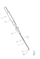
Figur 1- zeigt in perspektivischer Darstellung die Elektrodennadel und den Trokar einer Ausführungsform der erfinderischen Applikationsanordnung.
Figur 2- zeigt das
Ausführungsbeispiel aus Figur 1 mit in den Trokar eingeführter Elektrodennadel in perspektivischer Darstellung Figur 3- zeigt die Ausführungsform der erfinderischen Applikationsanordnung im Längsschnitt.
- Figur 4
- zeigt einen Querschnitt durch Hüllkörper und Schaft einer zweiten Ausführungsform der erfinderischen Applikationsanordnung.
Figur 5- zeigt einen Querschnitt durch Hüllkörper und Schaft einer dritten Ausführungsform der erfinderischen Applikationsvorrichtung.
- Figur 6
- zeigt eine erste Behandlungskonfiguration unter Verwendung der erfindungsgemäßen Applikationsanordnung.
Figur 7- zeigt eine zweite Behandlungskonfiguration unter Verwendung der erfindungsgemäßen Applikationsanordnung.
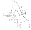
- Figuren 8A - 8C
- zeigen ein Beispiel für eine medizinische Behandlung mit der erfindungsgemäßen Applikationsanordnung.
- FIG. 1
- shows a perspective view of the electrode needle and the trocar of an embodiment of the inventive application arrangement.
- FIG. 2
- shows the embodiment of Figure 1 with inserted into the trocar electrode needle in a perspective view
- FIG. 3
- shows the embodiment of the inventive application arrangement in longitudinal section.
- FIG. 4
- shows a cross section through the enveloping body and shaft of a second embodiment of the inventive application arrangement.
- FIG. 5
- shows a cross section through the enveloping body and shaft of a third embodiment of the inventive application device.
- FIG. 6
- shows a first treatment configuration using the application arrangement according to the invention.
- FIG. 7
- shows a second treatment configuration using the application arrangement according to the invention.
- Figures 8A-8C
- show an example of a medical treatment with the application arrangement according to the invention.
In Figur 1 ist ein Ausführungsbeispiel für die erfindungsgemäße Applikationsanordnung in perspektivischer Ansicht dargestellt. Die Applikationsanordnung umfasst eine Elektrodennadel 1 mit einem Griffabschnitt 2 zum Handhaben der Elektrodennadel 1 und einem Schaft 3 aus einem elektrisch leitfähigen Material, der mit einem nicht dargestellten Hochfrequenzgenerator verbunden werden kann. Sie umfasst weiterhin einen Trokar 5 mit einem zum Einführen in Körpergewebe ausgebildeten Abschnitt 7 und einen zum Verbleib außerhalb des Körpergewebes ausgebildeten Abschnitt 11. Der Trokar 5 weist ein Lumen 13 (siehe Fig. 3) auf, durch das die Elektrodennadel 1 derart einzuführen ist, dass sich der Schaft 3 der Elektrodennadel 1 durch den Abschnitt 7 des Trokars 5 erstreckt.FIG. 1 shows an exemplary embodiment of the application arrangement according to the invention in a perspective view. The application arrangement comprises an
Ist die Elektrodennadel 1 in den Trokar 5 eingeführt (Figur 2), umschließt der Abschnitt 7 den Schaft 3 der Elektrodennadel 1 eng. Er besteht aus einem isolierenden Material, so dass er einen isolierenden Hüllkörper für den Schaft 3 der Elektrodennadel 1 bildet.If the
Mittels einer Verschiebeeinrichtung, die im in Fig. 3 dargestellten Ausführungsbeispiel ein zylindrisches Führungselement 15 umfasst, lässt sich die durch das Lumen 13 des Trokars 5 eingeführte Elektrodennadel 1 axial relativ zum Trokar 5 verschieben. Die Verschiebeeinrichtung umfasst dabei Markierungen, die im vorliegenden Ausführungsbeispiel als sich um den Umfang des Führungselements15 erstreckende Ringnuten 19 ausgebildet sind. Am Trokar 5 ist ein mit der Verschiebeeinrichtung 15 zusammenwirkender Klemmmechanismus 17 in Form einer zum Eingriff in die Ringnuten 19 ausgebildeten Kugel vorhanden. Die Kugel 17 wird durch eine vorgespannte Druckfeder 18 gegen die Umfangsfläche der Verschiebeeinrichtung gepresst und kann in die Ringnuten 19 einrasten, um die Verschiebeeinrichtung so gegen ein ungewolltes axiales Verschieben zu sichern. Statt der Ringnuten 19 können auch andere Arretiermittel Verwendung finden, sofern sie ein Einrasten der Kugel 17 ermöglichen.By means of a displacement device which comprises a
Durch das Verschieben der Elektrodennadel 1 mittels des Führungselements 15 relativ zum Trokar 5, und damit zum Hüllkörper 7, lässt sich die Länge des aus dem Hüllkörper 7 vorstehenden distalen Abschnitts des elektrisch leitenden Schaftes 3 variieren. Dabei bildet der aus dem distalen Ende des Hüllkörpers 7 vorstehende Abschnitt des Schaftes 3 die aktive Elektrode der Elektrodennadel 1, d. h. die nach dem Einbringen in das Körpergewebe mit diesem in Kontakt stehende aktive Elektrode.By moving the
Über eine nicht dargestellte, im Inneren des Schaftes 3 verlaufende Leitung ist dieser mit einem Hochfrequenzgenerator verbunden durch den an die aktive Elektrode eine Hochfrequenzspannung anlegbar ist. Beim Applizieren der Hochfrequenzspannung ist an der Außenseite des Körpers eine Gegenelektrode angelegt, so dass zwischen dem Schaft 3 und der Gegenelektrode ein Hochfrequenzstrom fließen kann, der zur Destruktion des Körpergewebes, bspw. eines Tumorgewebes, führt. Die Form und Größe der Destruktionszone lässt sich dabei durch die Länge des aus dem distalen Ende des Hüllkörpers 7 vorstehenden Abschnittes des Schaftes 3 variieren.Via a not shown, running in the interior of the
Der Schaft 3 der Elektrodennadel 1 kann darüber hinaus auch zum Einführen des Trokars 5 in das Körpergewebe verwendet werden. Dazu weist der Schaft 3 an seinem distalen Ende eine Spitze 23 zum Punktieren des Körpergewebes auf.The
Nach der Applikation des Hochfrequenzstromes kann der Trokar 5 im Körpergewebe verbleiben, wobei dann lediglich die Elektrodennadel 1 aus dem Trokar 5 herausgezogen wird. Er kann dann z.B. zum Einbringen von Medikamenten Verwendung finden. Der Hüllkörper 7 verhindert ein Verschleppen von Tumorzellen beim Herausziehen der Elektrodennadel.After the application of the high-frequency current, the
Wird der Trokar 5 nach dem Applizieren des Hochfrequenzstromes oder ggf. später aus dem Gewebe herausgezogen, kann beim Herausziehen ein Fibrinkleber in den Penetrationskanal eingeführt werden, um ihn zu versiegeln.If the
Die Applikationsanordnung umfasst eine weitere, zweite Elektrode 25, die als Gegenelektrode zur durch den Schaft 3 gebildeten Schaftelektrode dient. Sie ist auf dem äußeren Umfang des elektrisch isolierenden Hüllkörpers 7 angeordnet. Die axiale Länge der Gegenelektrode 25 beträgt etwa das 1-20-fache des Durchmessers des Schaftes 3.The application arrangement comprises a further,
Am distalen Ende des Hüllkörpers 7 erstreckt sich um den gesamten Umfang des Hüllkörpers 7 herum ein isolierender Abschnitt 27, der die Gegenelektrode 25 vom Schaft 3 isoliert und den Abstand der Gegenelektrode 25 von der Schaftelektrode festlegt. Die Gegenelektrode 25 weist eine vom Schaft 3 getrennte, durch den Mantel des Abschnittes 11 des Trokars 5 verlaufende elektrische Zuleitung 29 auf, die über die Kugel 17, im vorliegenden Ausführungsbeispiel eine elektrisch leitfähige Kugel, beispielsweise eine Metallkugel, und die Druckfeder 18 mit einem Anschluss 31 zum Anschließen eines Hochfrequenzgenerators verbunden ist. Mit dieser Ausgestaltung ist der bipolare Betrieb der Applikationsanordnung möglich.At the distal end of the enveloping
Im in Fig. 3 beschriebenen Ausführungsbeispiel kann der Hüllmantel 7 anstatt als Bestandteil des Trokars 5 auch als Bestandteil der Elektrodennadel 1 ausgebildet sein, wobei der Hüllmantel 7 weiterhin verschiebbar gegen den Schaft 3 ausgebildet ist. Eine derartig ausgestaltete Elektrodennadel kann auch ohne Trokar Verwendung finden. Das Vorhandensein eines Trokars ist daher zum Variieren der Länge des aus dem Hüllmantel 7 herausragenden Teils des Schaftes 3 nicht nötig.In the exemplary embodiment described in FIG. 3, instead of being formed as part of the
Weitere Ausführungsformen der erfindungsgemäßen Applikationsanordnung sind in den Figuren 4 und 5 dargestellt, die einen Querschnitt durch den Hüllkörper 7 und den in das Lumen des Hüllkörpers 7 eingeführten Schaft 3 darstellen. Im in Figur 5 dargestellten Ausführungsbeispiel erstreckt sich zwischen der Innenwand des Hüllkörpers 7 und der Außenfläche des Schaftes 3 ein Ringspalt 21, durch den beispielsweise eine Spülflüssigkeit in das zu behandelnde Gewebe eingeführt werden kann. Zudem ermöglicht es dieser Spalt 21 bei der Behandlung entstehenden Gasen aus dem Körper auszutreten.Further embodiments of the application arrangement according to the invention are shown in FIGS. 4 and 5, which represent a cross section through the enveloping
Eine alternative Ausgestaltung ist in Figur 5 dargestellt. Statt einem Spalt, der sich um den gesamten Umfang des Schaftes 3 erstreckt, sind in diesem Ausführungsbeispiel vier Spalte 21', die sich jeweils nur über einen Teil des Umfanges des Schaftes 3 erstrecken, ausgebildet. Sie sind als in axialer Richtung verlaufende Kerben an der Innenfläche des Hüllkörpers 7 ausgebildet und erstrecken sich über dessen gesamte Länge. Selbstverständlich kann die Zahl der Kerben auch größer oder kleiner als vier sein. Die Kerben müssen auch keinen viereckigen Querschnitt aufweisen sondern können beispielsweise auch einen dreieckigen oder rundlichen Querschnitt aufweisen.An alternative embodiment is shown in FIG. Instead of a gap which extends around the entire circumference of the
Die in Figur 5 dargestellte Ausgestaltung ermöglicht es, dass der Hüllkörper 7 den Schaft 3 eng umschließt und somit durch seine Reibung einem Verschieben des Schaftes gegen den Hüllkörper 7 entgegen wirkt. Gleichzeitig können jedoch der zu behandelnden Stelle im Körper durch die Spalte 21' Flüssigkeiten zugeführt werden. Ebenso können bei der Behandlung entstehende Gase entweichen. Die Abmessungen der Kerben 21' sind vorzugsweise so gewählt, dass ein vorbestimmter Flüssigkeitsdruck überschritten werden muss, damit die Flüssigkeit durch die Kerben 21' fließen kann. Körperflüssigkeiten, die zumeist elektrisch leitfähig sind, können dann nicht ohne weiteres in die Kerben 21' eindringen.The embodiment shown in FIG. 5 makes it possible for the enveloping
Zum Einführen von Flüssigkeiten in das Körpergewebe kann der Trokar an seinem zum Verbleib außerhalb des Körpers ausgebildeten Abschnitt 11 eine Phase für einen Spritzenanschluss aufweisen. Statt dem oder zusätzlich zum Spritzenanschluss kann der Trokar auch eine seitliche Flüssigkeitszuführung aufweisen.For introduction of fluids into the body tissue, the trocar may have a phase for a syringe port at its
Die Elektrodennadel 1 und/oder der zum Verbleib außerhalb des Körpers vorgesehene Abschnitt 11 des Trokars können außerdem mit Markierungen versehen sein, die dem Anwender zeigen, wie weit der Schaft 3 aus dem Hüllkörper 7 herausragt. Dies ist insbesondere wichtig, wenn die Applikationsanordnung bereits im Körper angeordnet ist, so dass der Anwender keinen visuellen Kontakt mit dem distalen Ende des Hüllkörpers 7 hat. Als solche Markierungen können beispielsweise die am Führungselement 15 angeordneten Ringnuten 19, farbige Markierungen oder eine Kombination aus beidem dienen.The
Zum Vereinfachen des Punktierens kann der Hüllkörper 7 an seinem distalen Ende außerdem eine Phase aufweisen, die in den Figuren nicht dargestellt ist.To simplify puncturing, the enveloping
Der Trokar 5 kann außerdem in einer alternativen Ausführungsform gegen das Austreten von Gasen und Körperflüssigkeiten abgedichtet sein. In diesem Fall kann die Dichtung beispielsweise als ringförmige Dichtung am Innenumfang des zum Verbleib außerhalb des Körpers vorgesehenen Abschnittes 11 angeordnet sein und derart ausgebildet sein, dass sie in die Ringnuten 19 des Führungselementes 15 einrasten kann, so dass die Dichtung gleichzeitig als Rastelement zum Arretieren der Elektrodennadel in einer axialen Position relativ zum Trokar zu verwenden ist. Die Dichtung kann alternativ auch am Führungselement angeordnet sein, wobei die Ringnuten dann an der Innenfläche des Abschnittes 11 angeordnet sind.The
Zur besseren Handhabung ist es insbesondere günstig, wenn der Trokar 5 und/oder der Griffabschnitt 2 der Elektrodennadel 1 eine Riffelung aufweisen.For better handling, it is particularly advantageous if the
In einer weiteren Ausgestaltung der Erfindung kann der Trokar mehrere achsenparallele, zum Einführen in Körpergewebe vorgesehene Abschnitte als Hüllkörper aufweisen. Die Hüllkörper besitzen jeweils ein Lumen, das in ein gemeinsames Lumen im zum Verbleib außerhalb des Körpers vorgesehenen Abschnitt des Trokars mündet, Durch einen solchen Trokar sind Elektrodennadeln mit mehreren Schäften in das Körpergewebe einführbar. Vorteilhafterweise sind die Hüllkörper getrennt voneinander gegen den jeweiligen, sich durch sie erstreckenden Schaft verschiebbar.In a further embodiment of the invention, the trocar can have a plurality of axially parallel sections, which are provided for insertion into body tissue, as enveloping bodies. The enveloping bodies each have a lumen which opens into a common lumen in the portion of the trocar intended to remain outside the body. Such a trocar introduces electrode needles with several shafts into the body tissue. Advantageously, the enveloping bodies are displaceable separately from one another against the respective shaft extending through them.
Es zeigt sich, dass durch die Anwendung unterschiedlicher aktiver Längen der aus den Hüllkörpern herausragenden Schäfte bei näherungsweise achsenparallel eingebrachten Elektroden die erreichte thermische Destruktionszone in weiten Bereichen modelliert werden kann. Somit lässt sich auch bei komplexen Tumorgeometrien eine optimale Anpassung der Destruktionszone erzielen.It can be seen that the use of different active lengths of the shafts projecting from the enveloping bodies with electrodes introduced approximately parallel to the axis enables the thermal destruction zone achieved to be modeled within wide ranges. Thus, an optimal adaptation of the destruction zone can be achieved even with complex tumor geometries.
Zwar ist in den mit Bezug auf die Ausführungsbeispiele dargestellten Applikationsanordnungen eine Verschiebeeinrichtung zum Verschieben des Hüllkörpers relativ zum Schaft der Elektrodennadel beschrieben, die Rastpositionen aufweist, jedoch kann auch eine Verschiebevorrichtung vorhanden sein, mit der sich eine stufenlose Verschiebung und Arretierung des Hüllkörpers relativ zum Schaft ermöglichen lässt. Dabei ist beispielsweise an eine im Trokar vorgesehene Fixierschraube zu denken, mit der der Hüllkörper am Schaft in jeder Relativposition zueinander sicher fixiert werden kann.Although in the application arrangements shown with reference to the embodiments described a displacement device for moving the enveloping body relative to the shaft of the electrode needle having detent positions, but also a displacement device may be provided with a stepless displacement and locking of the envelope allow relative to the shaft leaves. In this case, for example, to a provided in the trocar fixing screw to think, with the enveloping body can be securely fixed to each other on the shaft in each relative position.
Eine erste Behandlungskonfiguration unter Verwendung der erfindungsgemäßen Applikationsanordnung ist schematisch in Figur 6 dargestellt. Eine im bipolaren Modus betriebene Elektrodennadel 1 ist durch einen in das Körpergewebe eines Patienten 100 eingebrachten Trokar 5 in einen zu verödenden Bereich des Körpers eingeführt und über zwei Leitungen 115 mit einem Hochfrequenzgenerator 110 verbunden. Der Hochfrequenzgenerator 110 stellt den zum elektrothermischen Veröden nötigen Hochfrequenzstrom zur Verfügung, der durch einen die Kabel 115, die Elektrodennadel 1 sowie das Körpergewebe umfassenden Stromkreis fließt. Der Hochfrequenzstrom fließt dabei zwischen den Elektroden der Elektrodennadel 1 durch das zu verödende Körpergewebe.A first treatment configuration using the application arrangement according to the invention is shown schematically in FIG. An operating in bipolar
Eine zweite Behandlungskonfiguration unter Verwendung der erfindungsgemäßen Applikationsanordnung ist schematisch in Figur 7 dargestellt. Eine im monopolaren Modus betriebene Elektrodennadel 1 ist durch einen in das Körpergewebe eines Patienten 100 eingebrachten Trokar 5 in einen zu verödenden Bereich des Körpers eingeführt und über eine Leitung 115 mit einem Hochfrequenzgenerator 110 verbunden. Außerdem ist eine über eine Leitung 116 ebenfalls mit dem Hochfrequenzgenerator 110 verbundene Neutralelektrode 120 außen am Körper des Patienten 100 befestigt. Der Hochfrequenzgenerator 110 stellt den zum elektrothermischen Veröden nötigen Hochfrequenzstrom zur Verfügung, der durch einen das Kabel 115, das Kabel 116, die Elektrodennadel 1, die Neutralelektrode 120 sowie das Körpergewebe umfassenden Stromkreis fließt. Der Hochfrequenzstrom fließt dabei zwischen der Elektrodennadel 1 und der Neutralelektrode durch das zu verödende Körpergewebe.A second treatment configuration using the application arrangement according to the invention is shown schematically in FIG. An operated in monopolar
Mit Bezug auf die Figuren 8A bis 8C wird nun als ein Anwendungsbeispiel für die erfindungsgemäße Applikationsanordnung ein Volumenbehandlungsverfahren beschrieben. Die Volumenbehandlung dient zur Behandlung von pathogenem Tumorgewebe, vor allem in inneren Organen.With reference to FIGS. 8A to 8C, a volume treatment method will now be described as an example of application for the application arrangement according to the invention. The volume treatment is used to treat pathogenic tumor tissue, especially in internal organs.
Die Figuren 8A, B und C zeigen schematisch einen Teil des Körpergewebes 100 eines Patienten und ein darin befindliches Tumorgewebe 102. Zur Durchführung des Volumenbehandlungsverfahrens wird eine Anzahl Trokare 5 derart in den Körper des Patienten eingeführt, das die distalen Enden ihrer zum Einführen in den Körper vorgesehenen Abschnitte, d.h. der Hüllkörper 7, in das Tumorgewebe 102 hineinreichen oder an dieses heranreichen.Figures 8A, B and C show schematically a portion of the
Zum Einführen eines Trokars 5 wird eine Elektrodennadel 1 mit einer Spitze 23 am distalen Ende ihres Schaftes 3 in den Trokar 5 eingeführt und diese Kombination ins Körpergewebe 100 eingebracht, wobei die Spitze 23 zum Punktieren dient. Auf diese Weise werden alle Trokare 5 gesetzt.To insert a
Zum Zerstören des Tumorgewebes 102 wird zudem eine in den Figuren 8A bis 8C nicht dargestellte Neutralelektrode am Körper des Patienten angebracht, die als Gegenelektrode zum Schaft 3, oder besser gesagt der Schaftelektrode dient. Bei Anlegen einer Hochfrequenzspannung an die Elektrodennadel 1 fließt dann ein Strom zwischen dem aus dem distalen Ende des im Körpergewebe 100 befindlichen Hüllkörpers 7 herausragenden Abschnitt des Schaftes 3 und der Neutralelektrode. Damit wird eine Zerstörung des um den aktiven Schaft 3 herum befindlichen Tumorgewebes erreicht.For destroying the
Nach einer gewissen Zeit oder wenn ein bestimmter Destruktionsgrad des Tumorgewebes erreicht ist, wird die Zuführung der Hochfrequenzspannung unterbrochen, die Elektrodennadel 1 aus dem in Figur 9A dargestellten Trokar 5 herausgezogen und in den in Figur 8B dargestellten Trokar 5 eingeführt. Dort wird die Applikation der Hochfrequenzspannung wiederholt, um so einen anderen Abschnitt des Tumorgewebes 102 zu zerstören. Dasselbe wiederholt sich dann, wie in Figur 8C dargestellt, bei einem weiteren in das Körpergewebe 100 eingeführten Trokar 5.After a certain time or when a certain degree of destruction of the tumor tissue has been reached, the supply of high-frequency voltage is interrupted, the
Es können entweder alle in den Figuren 8A bis C dargestellten Trokare 5 vor der ersten Applikation des Hochfrequenzstromes eingeführt werden, oder es kann alternativ jeder Trokar unmittelbar vor dem ersten Applizieren des Hochfrequenzstroms an einer bestimmten Stelle eingeführt werden, d.h. die in den Figuren 8B und C zum Applizieren des Hochfrequenzstromes verwendeten Trokare 5 werden erst unmittelbar vor dem jeweiligen Applikationsschritt eingeführt. Mit jedem Applizieren von Hochfrequenzstrom an einer noch nicht behandelten Stelle wird dabei ein neuer Trokar eingeführt, so lange, bis alle Trokare gesetzt sind und die Applikation nur noch an zuvor bereits behandelten Stellen erfolgt, an denen sich schon Trokare befindet.Either all of the
Nach dem Applizieren des Hochfrequenzstroms verbleiben die Trokare 5 im zu behandelnden Körperbereich. Sie verhindern das Verschleppen von Tumorzellen beim Herausziehen der Nadel und dienen zum Zuführen von Medikamenten in das Therapievolumen, wie beispielsweise Schmerzmittel oder Chemotherapeutika. Außerdem können im Rahmen einer Feinnadelbiopsie dem Zielgewebe, also dem Tumorgewebe, Gewebeproben entnommen werden, um eine histologische Analyse durchzuführen. Nach dem Wiedereinführen der Elektrodennadel 1 in einen der Trokare 5 kann dann die Applikation der Hochfrequenzspannung wiederholt werden. Dabei kann jedes Mal die Länge des aktiven Bereichs des Schaftes 3 den klinischen Anforderungen entsprechend eingestellt werden.After application of the high-frequency current, the
Sobald die Behandlung insgesamt abgeschlossen ist, werden die Trokare 5 wieder aus dem Körpergewebe 100 entfernt.Once the treatment is complete, the
Alternativ können auch gleichzeitig Elektrodennadeln 1 in alle in den Figuren 8A bis 8C dargestellten Trokare 5 eingeführt sein und gleichzeitig betrieben werden. Die Elektrodennadeln können 1 können dabei z.B. auf einem einheitlichen Potential liegen, wobei der Strom dann zu einer oder mehreren Neutralelektroden fließt (monopolarer Betrieb). Alternativ ist auch ein multipolarer Betrieb, also einer, bei dem die Elektroden mit unterschiedlichen Potentialen betrieben werden, möglich. Der gleichzeitige Betrieb der Elektrodennadeln 1 ermöglicht nach dem Ssuperpositionsprinzip eine Effizienzsteigerung, die das Behandeln großer Tumore ermöglicht.Alternatively, electrode needles 1 can also be simultaneously introduced into all
In den Figuren 8A bis 8C sind jeweils 3 Trokare dargestellt. Die Zahle der in der Behandlung verwendeten Trokare ist jedoch nicht auf drei festgelegt, vielmehr kann sie der Art der Behandlung sowie der Art und/oder der Größe des Tumors angepasst werden.FIGS. 8A to 8C each show three trocars. However, the number of trocars used in the treatment is not fixed at three but may be adjusted to the nature of the treatment as well as the nature and / or size of the tumor.
Claims (16)
Applications Claiming Priority (2)
| Application Number | Priority Date | Filing Date | Title |
|---|---|---|---|
| DE10224153A DE10224153A1 (en) | 2002-05-27 | 2002-05-27 | therapy device |
| EP03730081A EP1511436B1 (en) | 2002-05-27 | 2003-05-20 | Insulating trocart |
Related Parent Applications (2)
| Application Number | Title | Priority Date | Filing Date |
|---|---|---|---|
| EP03730081.1 Division | 2003-05-20 | ||
| EP03730081A Division EP1511436B1 (en) | 2002-05-27 | 2003-05-20 | Insulating trocart |
Publications (2)
| Publication Number | Publication Date |
|---|---|
| EP1862139A2 true EP1862139A2 (en) | 2007-12-05 |
| EP1862139A3 EP1862139A3 (en) | 2011-02-09 |
Family
ID=29432487
Family Applications (2)
| Application Number | Title | Priority Date | Filing Date |
|---|---|---|---|
| EP03730081A Expired - Lifetime EP1511436B1 (en) | 2002-05-27 | 2003-05-20 | Insulating trocart |
| EP07075546A Withdrawn EP1862139A3 (en) | 2002-05-27 | 2003-05-20 | Therapy equipment |
Family Applications Before (1)
| Application Number | Title | Priority Date | Filing Date |
|---|---|---|---|
| EP03730081A Expired - Lifetime EP1511436B1 (en) | 2002-05-27 | 2003-05-20 | Insulating trocart |
Country Status (9)
| Country | Link |
|---|---|
| US (3) | US20050228374A1 (en) |
| EP (2) | EP1511436B1 (en) |
| JP (1) | JP2005527291A (en) |
| CN (1) | CN100370956C (en) |
| AT (1) | ATE372091T1 (en) |
| AU (1) | AU2003240682A1 (en) |
| DE (2) | DE10224153A1 (en) |
| ES (1) | ES2292970T3 (en) |
| WO (1) | WO2003099150A2 (en) |
Families Citing this family (12)
| Publication number | Priority date | Publication date | Assignee | Title |
|---|---|---|---|---|
| JP5090334B2 (en) | 2005-03-17 | 2012-12-05 | ストライカー コーポレーション | Surgical instrument device |
| US8657814B2 (en) * | 2005-08-22 | 2014-02-25 | Medtronic Ablation Frontiers Llc | User interface for tissue ablation system |
| EP2047817B1 (en) * | 2006-07-28 | 2012-10-31 | Kabushiki Kaisha Top | Electrode needle device with temperature sensor |
| US20080191604A1 (en) * | 2006-09-27 | 2008-08-14 | Evident Technologies | Retro-emission systems comprising microlens arrays and luminescent emitters |
| US7828775B2 (en) * | 2008-04-11 | 2010-11-09 | Tyco Healthcare Group Lp | Telescoping cannula |
| AU2010218473B2 (en) | 2009-02-26 | 2014-03-06 | Stryker Corporation | Surgical tool arrangement having a handpiece usable with multiple surgical tools |
| US8409188B2 (en) | 2010-03-26 | 2013-04-02 | Covidien Lp | Ablation devices with adjustable radiating section lengths, electrosurgical systems including same, and methods of adjusting ablation fields using same |
| KR101024468B1 (en) * | 2010-08-20 | 2011-03-23 | 정일우 | Operating system for exposing tumor mass |
| WO2019095189A1 (en) * | 2017-11-16 | 2019-05-23 | 中国人民解放军火箭军总医院 | Steep pulse electric field tumor treatment electrode |
| US11534235B2 (en) | 2019-04-04 | 2022-12-27 | Acclarent, Inc. | Needle instrument for posterior nasal neurectomy ablation |
| CN110179534A (en) * | 2019-06-27 | 2019-08-30 | 安徽邵氏华艾生物医疗电子科技有限公司 | A kind of nano-knife ablating electrode |
| US11246637B2 (en) | 2020-05-11 | 2022-02-15 | Alphatec Spine, Inc. | Stimulating targeting needle |
Citations (4)
| Publication number | Priority date | Publication date | Assignee | Title |
|---|---|---|---|---|
| WO1997024074A1 (en) * | 1995-12-29 | 1997-07-10 | Microgyn, Inc. | Apparatus and method for electrosurgery |
| WO1999016371A1 (en) * | 1997-09-30 | 1999-04-08 | Boston Scientific Corporation | Apparatus for electro-surgical tissue removal |
| JP2000201946A (en) * | 1999-01-14 | 2000-07-25 | Olympus Optical Co Ltd | Resectoscope device |
| WO2001012089A1 (en) * | 1999-08-12 | 2001-02-22 | Somnus Medical Technologies, Inc. | Nerve stimulation and tissue ablation apparatus and method |
Family Cites Families (41)
| Publication number | Priority date | Publication date | Assignee | Title |
|---|---|---|---|---|
| US5370675A (en) * | 1992-08-12 | 1994-12-06 | Vidamed, Inc. | Medical probe device and method |
| US5421819A (en) * | 1992-08-12 | 1995-06-06 | Vidamed, Inc. | Medical probe device |
| DE9290164U1 (en) * | 1992-01-21 | 1994-09-15 | Valleylab Inc | Electrosurgical control for a trocar |
| AU5456494A (en) * | 1992-11-13 | 1994-06-08 | American Cardiac Ablation Co., Inc. | Fluid cooled electrosurgical probe |
| AU685086B2 (en) * | 1993-02-02 | 1998-01-15 | Vidamed, Inc. | Transurethral needle ablation device |
| US5599345A (en) * | 1993-11-08 | 1997-02-04 | Zomed International, Inc. | RF treatment apparatus |
| US5728143A (en) * | 1995-08-15 | 1998-03-17 | Rita Medical Systems, Inc. | Multiple antenna ablation apparatus and method |
| US6641580B1 (en) * | 1993-11-08 | 2003-11-04 | Rita Medical Systems, Inc. | Infusion array ablation apparatus |
| US5536267A (en) * | 1993-11-08 | 1996-07-16 | Zomed International | Multiple electrode ablation apparatus |
| US5472441A (en) * | 1993-11-08 | 1995-12-05 | Zomed International | Device for treating cancer and non-malignant tumors and methods |
| US6071280A (en) * | 1993-11-08 | 2000-06-06 | Rita Medical Systems, Inc. | Multiple electrode ablation apparatus |
| US5709679A (en) * | 1994-03-03 | 1998-01-20 | Essig; Mitchell N. | Myoma removal technique and associated surgical device |
| US5728079A (en) * | 1994-09-19 | 1998-03-17 | Cordis Corporation | Catheter which is visible under MRI |
| US5545171A (en) * | 1994-09-22 | 1996-08-13 | Vidamed, Inc. | Anastomosis catheter |
| EP2070486A1 (en) * | 1994-12-13 | 2009-06-17 | Torben Lorentzen | An electrosurgical instrument for tissue ablation, an apparatus, and a method for providing a lesion in damaged and diseased tissue from a mammal |
| US5868740A (en) * | 1995-03-24 | 1999-02-09 | Board Of Regents-Univ Of Nebraska | Method for volumetric tissue ablation |
| US6575969B1 (en) * | 1995-05-04 | 2003-06-10 | Sherwood Services Ag | Cool-tip radiofrequency thermosurgery electrode system for tumor ablation |
| US6080150A (en) * | 1995-08-15 | 2000-06-27 | Rita Medical Systems, Inc. | Cell necrosis apparatus |
| US5913855A (en) * | 1995-08-15 | 1999-06-22 | Rita Medical Systems, Inc. | Multiple antenna ablation apparatus and method |
| US5672174A (en) * | 1995-08-15 | 1997-09-30 | Rita Medical Systems, Inc. | Multiple antenna ablation apparatus and method |
| US5980517A (en) * | 1995-08-15 | 1999-11-09 | Rita Medical Systems, Inc. | Cell necrosis apparatus |
| US5868742A (en) * | 1995-10-18 | 1999-02-09 | Conmed Corporation | Auxiliary reference electrode and potential referencing technique for endoscopic electrosurgical instruments |
| DE19541566A1 (en) * | 1995-11-08 | 1997-05-15 | Laser & Med Tech Gmbh | Application system for HF surgery for interstitial thermotherapy in bipolar technology (HF-ITT) |
| EP0912140B1 (en) * | 1996-06-24 | 2004-08-25 | Karl Storz GmbH & Co. KG | Endoscopic instrument which can be bent |
| AU1372099A (en) * | 1997-11-03 | 1999-05-24 | Rita Medical Systems, Inc. | Multiple antenna ablation apparatus and method |
| US6312429B1 (en) * | 1998-09-01 | 2001-11-06 | Senorx, Inc. | Electrosurgical lesion location device |
| JPH11290331A (en) * | 1998-04-09 | 1999-10-26 | Olympus Optical Co Ltd | Device for treating prostatic hypertrophy |
| JPH11318926A (en) * | 1998-05-08 | 1999-11-24 | Olympus Optical Co Ltd | Treatment instrument for high frequency therapy |
| US6315777B1 (en) * | 1998-07-07 | 2001-11-13 | Medtronic, Inc. | Method and apparatus for creating a virtual electrode used for the ablation of tissue |
| US6238393B1 (en) * | 1998-07-07 | 2001-05-29 | Medtronic, Inc. | Method and apparatus for creating a bi-polar virtual electrode used for the ablation of tissue |
| US6190383B1 (en) * | 1998-10-21 | 2001-02-20 | Sherwood Services Ag | Rotatable electrode device |
| JP3602794B2 (en) * | 1998-11-16 | 2004-12-15 | イアン コスメスク, | Multi-function telescoping instrument |
| US6306132B1 (en) * | 1999-06-17 | 2001-10-23 | Vivant Medical | Modular biopsy and microwave ablation needle delivery apparatus adapted to in situ assembly and method of use |
| US6626899B2 (en) * | 1999-06-25 | 2003-09-30 | Nidus Medical, Llc | Apparatus and methods for treating tissue |
| US7014633B2 (en) * | 2000-02-16 | 2006-03-21 | Trans1, Inc. | Methods of performing procedures in the spine |
| US6986686B2 (en) * | 2001-02-23 | 2006-01-17 | Olympus Corporation | Electrical plug for supplying electric power from a power supply to a medical instrument |
| US6740081B2 (en) * | 2002-01-25 | 2004-05-25 | Applied Medical Resources Corporation | Electrosurgery with improved control apparatus and method |
| US6974455B2 (en) * | 2002-04-10 | 2005-12-13 | Boston Scientific Scimed, Inc. | Auto advancing radio frequency array |
| US7027851B2 (en) * | 2002-10-30 | 2006-04-11 | Biosense Webster, Inc. | Multi-tip steerable catheter |
| US8377082B2 (en) * | 2003-01-14 | 2013-02-19 | Medtronic, Inc. | Methods and apparatus for making precise incisions in body vessels |
| US7195631B2 (en) * | 2004-09-09 | 2007-03-27 | Sherwood Services Ag | Forceps with spring loaded end effector assembly |
-
2002
- 2002-05-27 DE DE10224153A patent/DE10224153A1/en not_active Withdrawn
-
2003
- 2003-05-20 EP EP03730081A patent/EP1511436B1/en not_active Expired - Lifetime
- 2003-05-20 JP JP2004506678A patent/JP2005527291A/en active Pending
- 2003-05-20 AU AU2003240682A patent/AU2003240682A1/en not_active Abandoned
- 2003-05-20 DE DE50308126T patent/DE50308126D1/en not_active Expired - Lifetime
- 2003-05-20 ES ES03730081T patent/ES2292970T3/en not_active Expired - Lifetime
- 2003-05-20 AT AT03730081T patent/ATE372091T1/en not_active IP Right Cessation
- 2003-05-20 EP EP07075546A patent/EP1862139A3/en not_active Withdrawn
- 2003-05-20 US US10/515,867 patent/US20050228374A1/en not_active Abandoned
- 2003-05-20 CN CNB038119323A patent/CN100370956C/en not_active Expired - Fee Related
- 2003-05-20 WO PCT/EP2003/005303 patent/WO2003099150A2/en active IP Right Grant
-
2009
- 2009-08-10 US US12/538,208 patent/US20090299366A1/en not_active Abandoned
- 2009-08-10 US US12/462,833 patent/US20090306656A1/en not_active Abandoned
Patent Citations (4)
| Publication number | Priority date | Publication date | Assignee | Title |
|---|---|---|---|---|
| WO1997024074A1 (en) * | 1995-12-29 | 1997-07-10 | Microgyn, Inc. | Apparatus and method for electrosurgery |
| WO1999016371A1 (en) * | 1997-09-30 | 1999-04-08 | Boston Scientific Corporation | Apparatus for electro-surgical tissue removal |
| JP2000201946A (en) * | 1999-01-14 | 2000-07-25 | Olympus Optical Co Ltd | Resectoscope device |
| WO2001012089A1 (en) * | 1999-08-12 | 2001-02-22 | Somnus Medical Technologies, Inc. | Nerve stimulation and tissue ablation apparatus and method |
Also Published As
| Publication number | Publication date |
|---|---|
| ATE372091T1 (en) | 2007-09-15 |
| US20090306656A1 (en) | 2009-12-10 |
| DE50308126D1 (en) | 2007-10-18 |
| WO2003099150A3 (en) | 2004-03-18 |
| US20090299366A1 (en) | 2009-12-03 |
| US20050228374A1 (en) | 2005-10-13 |
| ES2292970T3 (en) | 2008-03-16 |
| JP2005527291A (en) | 2005-09-15 |
| CN1655728A (en) | 2005-08-17 |
| CN100370956C (en) | 2008-02-27 |
| DE10224153A1 (en) | 2003-12-11 |
| WO2003099150A2 (en) | 2003-12-04 |
| EP1511436B1 (en) | 2007-09-05 |
| EP1862139A3 (en) | 2011-02-09 |
| EP1511436A2 (en) | 2005-03-09 |
| AU2003240682A1 (en) | 2003-12-12 |
Similar Documents
| Publication | Publication Date | Title |
|---|---|---|
| DE19847852B4 (en) | Treatment instrument for an endoscope | |
| DE4305663C2 (en) | Medical probe device | |
| DE69532140T2 (en) | Ablation device with multiple electrodes | |
| DE60114857T2 (en) | Steerable sphincterotome | |
| EP0205851B1 (en) | Catheter | |
| DE60220376T2 (en) | Steerable sphincterotome for cannulation, papillotomy and sphincterotomy | |
| DE602005001776T2 (en) | Bipolar electrosurgical sling | |
| DE69629948T2 (en) | DEVICE FOR ABLATION OF TISSUE MATERIALS | |
| EP1292230B1 (en) | Surgical, grooved director | |
| DE19713797A1 (en) | Electrosurgical instrument for use in e.g. myoma necrosis | |
| EP2956071B1 (en) | Set for peripheral nerve blocking | |
| DE2009093B2 (en) | CATHETER WITH AN ELECTRIC LETIER | |
| EP1044654A2 (en) | Arrangement for electrothermal treatment of the human or animal body | |
| EP1511436B1 (en) | Insulating trocart | |
| DE3050386T1 (en) | ||
| DE19849974C2 (en) | Endoscopic introducer | |
| EP0315730A2 (en) | Device for dilating and/or opening blood vessels | |
| DE3642077C2 (en) | Device with a generator and an associated application probe | |
| EP1408839A1 (en) | Surgical, grooved director for collecting tissue in a minimally invasive manner | |
| DE69432361T2 (en) | CATHETER FOR VARIOUS IN-SITU TISSUE THERAPIES | |
| EP1517646B1 (en) | Electrode needle | |
| DE102007042524A1 (en) | Coagulation template and application device | |
| WO2001034046A1 (en) | Device for gently removing tissue from animal or human tissue | |
| DE102009053438B4 (en) | Resectoscope | |
| EP3471642B1 (en) | Surgical instrument for electrotomy and tool for same |
Legal Events
| Date | Code | Title | Description |
|---|---|---|---|
| PUAI | Public reference made under article 153(3) epc to a published international application that has entered the european phase |
Free format text: ORIGINAL CODE: 0009012 |
|
| AC | Divisional application: reference to earlier application |
Ref document number: 1511436 Country of ref document: EP Kind code of ref document: P |
|
| AK | Designated contracting states |
Kind code of ref document: A2 Designated state(s): AT BE BG CH CY CZ DE DK EE ES FI FR GB GR HU IE IT LI LU MC NL PT RO SE SI SK TR |
|
| PUAL | Search report despatched |
Free format text: ORIGINAL CODE: 0009013 |
|
| AK | Designated contracting states |
Kind code of ref document: A3 Designated state(s): AT BE BG CH CY CZ DE DK EE ES FI FR GB GR HU IE IT LI LU MC NL PT RO SE SI SK TR |
|
| AKY | No designation fees paid | ||
| REG | Reference to a national code |
Ref country code: DE Ref legal event code: R108 |
|
| REG | Reference to a national code |
Ref country code: DE Ref legal event code: R108 Effective date: 20111012 |
|
| STAA | Information on the status of an ep patent application or granted ep patent |
Free format text: STATUS: THE APPLICATION IS DEEMED TO BE WITHDRAWN |
|
| 18D | Application deemed to be withdrawn |
Effective date: 20110210 |