JP5090334B2 - Surgical instrument device - Google Patents
Surgical instrument device Download PDFInfo
- Publication number
- JP5090334B2 JP5090334B2 JP2008502112A JP2008502112A JP5090334B2 JP 5090334 B2 JP5090334 B2 JP 5090334B2 JP 2008502112 A JP2008502112 A JP 2008502112A JP 2008502112 A JP2008502112 A JP 2008502112A JP 5090334 B2 JP5090334 B2 JP 5090334B2
- Authority
- JP
- Japan
- Prior art keywords
- hub
- handpiece
- housing
- electrode
- surgical
- Prior art date
- Legal status (The legal status is an assumption and is not a legal conclusion. Google has not performed a legal analysis and makes no representation as to the accuracy of the status listed.)
- Expired - Fee Related
Links
- 0 CC*CC1C*CC1 Chemical compound CC*CC1C*CC1 0.000 description 1
Images


Classifications
-
- A—HUMAN NECESSITIES
- A61—MEDICAL OR VETERINARY SCIENCE; HYGIENE
- A61B—DIAGNOSIS; SURGERY; IDENTIFICATION
- A61B18/00—Surgical instruments, devices or methods for transferring non-mechanical forms of energy to or from the body
- A61B18/04—Surgical instruments, devices or methods for transferring non-mechanical forms of energy to or from the body by heating
- A61B18/12—Surgical instruments, devices or methods for transferring non-mechanical forms of energy to or from the body by heating by passing a current through the tissue to be heated, e.g. high-frequency current
- A61B18/14—Probes or electrodes therefor
- A61B18/1485—Probes or electrodes therefor having a short rigid shaft for accessing the inner body through natural openings
-
- A—HUMAN NECESSITIES
- A61—MEDICAL OR VETERINARY SCIENCE; HYGIENE
- A61B—DIAGNOSIS; SURGERY; IDENTIFICATION
- A61B17/00—Surgical instruments, devices or methods, e.g. tourniquets
- A61B17/32—Surgical cutting instruments
- A61B17/320016—Endoscopic cutting instruments, e.g. arthroscopes, resectoscopes
- A61B17/32002—Endoscopic cutting instruments, e.g. arthroscopes, resectoscopes with continuously rotating, oscillating or reciprocating cutting instruments
-
- A—HUMAN NECESSITIES
- A61—MEDICAL OR VETERINARY SCIENCE; HYGIENE
- A61B—DIAGNOSIS; SURGERY; IDENTIFICATION
- A61B17/00—Surgical instruments, devices or methods, e.g. tourniquets
- A61B17/32—Surgical cutting instruments
-
- A—HUMAN NECESSITIES
- A61—MEDICAL OR VETERINARY SCIENCE; HYGIENE
- A61B—DIAGNOSIS; SURGERY; IDENTIFICATION
- A61B18/00—Surgical instruments, devices or methods for transferring non-mechanical forms of energy to or from the body
- A61B18/04—Surgical instruments, devices or methods for transferring non-mechanical forms of energy to or from the body by heating
- A61B18/12—Surgical instruments, devices or methods for transferring non-mechanical forms of energy to or from the body by heating by passing a current through the tissue to be heated, e.g. high-frequency current
- A61B18/14—Probes or electrodes therefor
-
- A—HUMAN NECESSITIES
- A61—MEDICAL OR VETERINARY SCIENCE; HYGIENE
- A61B—DIAGNOSIS; SURGERY; IDENTIFICATION
- A61B17/00—Surgical instruments, devices or methods, e.g. tourniquets
- A61B2017/0046—Surgical instruments, devices or methods, e.g. tourniquets with a releasable handle; with handle and operating part separable
-
- A—HUMAN NECESSITIES
- A61—MEDICAL OR VETERINARY SCIENCE; HYGIENE
- A61B—DIAGNOSIS; SURGERY; IDENTIFICATION
- A61B18/00—Surgical instruments, devices or methods for transferring non-mechanical forms of energy to or from the body
- A61B2018/00053—Mechanical features of the instrument of device
- A61B2018/00172—Connectors and adapters therefor
- A61B2018/00178—Electrical connectors
Description
本発明は、外科用器具装置に係り、特に生体組織の機械的切除、電気焼灼、および電気的除去(アブレーション)を可能とする装置、また、取り外し可能に装着した数多くの外科用器具や装置を駆動できる汎用外科手術ハンドピースとしての外科用器具装置に関するものである。 The present invention relates to a surgical instrument device, and more particularly to a device that enables mechanical excision, electrocautery, and electrical removal (ablation) of biological tissue, and a number of surgical instruments and devices that are detachably mounted. The present invention relates to a surgical instrument device as a general-purpose surgical handpiece that can be driven.
生体組織切除用に設計した外科用器具は、何年にもわたり使用されてきた。このような外科用器具は、典型的には、電動ハンドピースと、このハンドピースの遠方端に固定した切除用器具とからなる。この外科用器具は、ハンドピースモータの出力軸に駆動係合したハブと、このハブに固定した駆動軸とを備えた内部駆動部材を有している。そのハブの遠方端には、切除道具すなわち切除ヘッドが形成されている。外側の管状のハウジング要素は、内部駆動部材の駆動軸の周囲に配置され、切除窓部を有している。この切除窓部は、可動型の切除ヘッドと協力して切除窓部近傍に位置する患者の対象組織を処理する。 Surgical instruments designed for tissue removal have been used for many years. Such surgical instruments typically consist of an electric handpiece and an ablation instrument secured to the distal end of the handpiece. The surgical instrument has an internal drive member having a hub drivingly engaged with an output shaft of a handpiece motor and a drive shaft fixed to the hub. A cutting tool or cutting head is formed at the distal end of the hub. The outer tubular housing element is arranged around the drive shaft of the internal drive member and has a cutting window. This excision window part cooperates with the movable excision head to process the target tissue of the patient located near the excision window part.
また、電気外科用器具(electrosurgical tool)も何年にもわたり使用されてきており、これは電気エネルギーを利用して対象たる患者の組織を様々な方法で処理する。例えば、外科手術の際に血管を開披および閉鎖するために電気焼灼が行われ、血液喪失が回避される。また、組織を蒸発または除去するため、電気エネルギーを利用したアブレーションが行われる。電気外科用プローブは、供給される電力レベルに応じて、これらの両方の機能を果たすように設計されている。さらに、従来の機器には、単極または双極の電気外科用器具がある。単極の外科用器具は、そこに設けた活性電極からの電流を、患者の体を介して帰還電極に導く。この帰還電極は、典型的には患者に装着した接地パッドである。他方、双極の外科用器具は、活性電極および帰還電極の両方を有しており、電流は活性電極から接触組織を介して帰還電極に導かれる。 Electrosurgical tools have also been used for many years, which utilize electrical energy to treat the subject's patient tissue in various ways. For example, electrocautery is performed to open and close blood vessels during surgery to avoid blood loss. Also, ablation using electrical energy is performed to evaporate or remove tissue. Electrosurgical probes are designed to perform both of these functions depending on the power level supplied. In addition, conventional instruments include monopolar or bipolar electrosurgical instruments. A monopolar surgical instrument directs current from an active electrode provided therein to a return electrode through the patient's body. This return electrode is typically a ground pad worn on the patient. On the other hand, bipolar surgical instruments have both an active electrode and a return electrode, and current is conducted from the active electrode through the contact tissue to the return electrode.
上記の機能の両方を有する外科用器具が知られている。例えば、米国特許第4815462号明細書は、外側管路を有するハウジングと、外側管路内に配置した回転可能な切除ブレードとを備えた脂肪組織切除装置を開示している。この回転可能な切除ブレードの遠方端すなわち先端は、血管の電気凝固に使用できるようこの先端を加熱する電気回路に相互連結されている。
また、米国特許第5941876号明細書は、電気外科用回転切除装置を開示している。この装置は、中に回転切除要素が配置される外側管構造を有している。この外側管構造は、効果的に電気エネルギーを回転カッタに伝達する整流子を有しており、エネルギー伝達活性電極として役立つ。前記外科用回転切除装置は、例えば、回転カッタを活性電極として使用することで、また接地パッドを帰還電極として使用することで、単極装置として使用することができる。あるいは、前記外科用回転切除装置は、外側管状構造の一部を構成するシースの露出部を帰還電極として使用することで、双極装置として使用することができる。
更に、米国特許第6193715号明細書は、機械的切除器具のような既存の外科用器具に後付してそれを双極の電気外科用器具として転換するアダプタユニットを開示している。またこの電気外科用器具は、単極の外科用器具を双極の外科用器具に転換することもできる。前記アダプタユニットは、管状シースすなわち管路を備えおり、この管状シースの一端には、電源に連絡する取付ブロックが設けられている。この取付ブロックは、一対の電気信号コネクタピンを構成する。機械的切除装置がアダプタユニット内に配置されると、これらの電気信号コネクタピンの一つが切除装置の導電部と電気接続し、電気信号コネクタピンの他方が管状シースの導電性中間層と電気接続し、接続装置を双極の電気外科用器具に効果的に転換する。
US Pat. No. 5,941,876 also discloses an electrosurgical rotary ablation device. The device has an outer tube structure in which a rotating cutting element is disposed. This outer tube structure has a commutator that effectively transfers electrical energy to the rotating cutter and serves as an energy transfer active electrode. The surgical rotary ablation device can be used as a monopolar device, for example, using a rotary cutter as the active electrode and using a ground pad as the return electrode. Alternatively, the surgical rotary excision device can be used as a bipolar device by using the exposed portion of the sheath that forms part of the outer tubular structure as a return electrode.
In addition, US Pat. No. 6,193,715 discloses an adapter unit that retrofits an existing surgical instrument such as a mechanical ablation instrument and converts it as a bipolar electrosurgical instrument. The electrosurgical instrument can also convert a monopolar surgical instrument to a bipolar surgical instrument. The adapter unit includes a tubular sheath, that is, a conduit, and an attachment block communicating with a power source is provided at one end of the tubular sheath. This mounting block constitutes a pair of electrical signal connector pins. When the mechanical ablation device is placed in the adapter unit, one of these electrical signal connector pins is electrically connected to the conductive portion of the ablation device, and the other electrical signal connector pin is electrically connected to the conductive intermediate layer of the tubular sheath. And effectively convert the connecting device into a bipolar electrosurgical instrument.
ところが、上記の特許文献1、2において、回転ブレードの先端はエネルギー伝達活性電極として利用されるので、回転ブレードの先端で画定される活性電極の表面領域が変化し、エネルギー伝達が一定でなく性能が一定でないということである。
また、上記の特許文献3において、アダプタユニットは、既存の切除装置ハウジングを覆って追加ハウジング(すなわちシース)を配置することが必要であり、これは装置の全体サイズが非常に増大することになるとともに、患者に形成する入口を拡大させることが必要となる。
However, in the above Patent Documents 1 and 2, since the tip of the rotating blade is used as an energy transmission active electrode, the surface area of the active electrode defined by the tip of the rotating blade changes, and the energy transfer is not constant and performance. Is not constant.
Further, in Patent Document 3 described above, the adapter unit needs to arrange an additional housing (that is, a sheath) over the existing ablation device housing, which greatly increases the overall size of the device. At the same time, it is necessary to enlarge the entrance formed in the patient.
そこで、既知の装置の上記の欠点をなくすか少なくとも最小限にするため、本発明による外科用器具装置は、電動ハンドピースに取り外し可能に装着する最少サイズの一体化器具を提供するものであるが、対象組織にエネルギー伝達する回転部品を使用しないものであって、機械的切除界面におけるエネルギー伝達を改良する表面領域が小さな静止ハウジングに活性電極を設けているものである。より具体的には、本発明の外科用器具装置は、外側ハウジング要素と、このハウジング要素に固定したカニューレすなわちシースとを備えており、この外側ハウジング要素は、ハンドピースの結合装置に取り付けるハブ装置を有しており、この中に可動切除要素が配置される。このカニューレの遠方端には、切除要素の切除ヘッドを露出させるよう、開口部すなわち窓部を有している。電気エネルギーはカニューレに設けた電極装置に供給されるとともに、電極は切除界面の窓部の直ぐ近傍に設けられる。電気エネルギーは、接地パッドかカニューレの導電部を介して戻る。 Thus, in order to eliminate or at least minimize the above disadvantages of known devices, the surgical instrument device according to the present invention provides a minimally sized integrated instrument that is removably attached to an electric handpiece. It does not use rotating parts that transmit energy to the target tissue, and has an active electrode in a stationary housing with a small surface area that improves energy transfer at the mechanical ablation interface. More specifically, the surgical instrument device of the present invention comprises an outer housing element and a cannula or sheath secured to the housing element, the outer housing element being a hub device that attaches to a handpiece coupling device. In which the movable cutting element is arranged. The distal end of the cannula has an opening or window to expose the cutting head of the cutting element. Electrical energy is supplied to an electrode device provided on the cannula and the electrode is provided in the immediate vicinity of the window at the ablation interface. Electrical energy returns through the ground pad or the conductive portion of the cannula.
本発明は、
外科用電動ハンドピースに搭載するための双極外科用器具であって、この双極外科用器具は、外科用ハンドピースの駆動部材により駆動するように構成したハブと、このハブに連結しておりその遠方端に切除要素を有する細長い堅固な駆動軸とを備えた切除アセンブリを設け、
近傍端を構成する取付用のハブを有する外側ハウジングアセンブリを設け、ここで、前記ハブは、外科用ハンドピースに設けた結合装置と相互連結するように構成した取付装置を有しており、
さらに前記双極外科用器具は、前記駆動軸および前記切除要素が中に可動配置された細長く略管状の外側カニューレを設け、ここで、この外側カニューレは、前記ハブから突出しておりその遠方端には前記切除要素付近で開口部を有しており、
さらに前記双極外科用器具は、前記カニューレの前記開口部の各両側に設けた第1電極および第2電極を有する電極装置を設け、ここで、前記第1電極は、エネルギー伝達活性電極を構成し、前記第2電極は、帰還電極を構成することを特徴とする。
The present invention
A bipolar surgical instrument for mounting on a surgical power handpiece, the bipolar surgical instrument being coupled to and coupled to a hub configured to be driven by a drive member of the surgical handpiece Providing an ablation assembly with an elongate rigid drive shaft having an ablation element at the distal end;
Providing an outer housing assembly having an attachment hub defining a proximal end, wherein the hub comprises an attachment device configured to interconnect with a coupling device provided on the surgical handpiece;
The bipolar surgical instrument further includes an elongated, generally tubular outer cannula with the drive shaft and the ablation element movably disposed therein, wherein the outer cannula protrudes from the hub and is disposed at a distal end thereof. Having an opening near the ablation element;
The bipolar surgical instrument further includes an electrode device having a first electrode and a second electrode provided on each side of the opening of the cannula, wherein the first electrode constitutes an energy transfer active electrode. The second electrode constitutes a return electrode.
本発明は、可動切除要素をエネルギー伝達電極として使用しないため、切除界面に伝達されるエネルギーは一定であり、器具の性能がより一定となる。さらに、可動切除要素が活性電極として使用されないため、機械的切除要素と外側ハウジング要素とを電気的に分離する必要がない。
また、本発明は、ハンドピースと一体化器具とを電気結合しており、この結合により電気エネルギーをハンドピースを介して一体化器具の電極装置に供給でき、よって別個の電力ケーブルを設ける必要がなくなる。
更に、本発明は、それぞれ一つ以上の機能を有する様々な外科用器具を取付および操作可能な汎用ハンドピースに関する。
Since the present invention does not use the movable ablation element as an energy transfer electrode, the energy transferred to the ablation interface is constant and the performance of the instrument is more constant. Furthermore, since the movable cutting element is not used as the active electrode, there is no need to electrically isolate the mechanical cutting element and the outer housing element.
In addition, the present invention electrically couples the handpiece and the integrated instrument, and this coupling allows electric energy to be supplied to the electrode device of the integrated instrument via the handpiece, so that it is necessary to provide a separate power cable. Disappear.
Furthermore, the present invention relates to a universal handpiece capable of attaching and operating various surgical instruments each having one or more functions.
本発明の外科用器具装置は、電動ハンドピースに取り外し可能に装着する最少サイズの一体化器具を提供し、対象組織にエネルギー伝達する回転部品を使用しない。
以下、図面に基づいてこの発明の実施例を詳細且つ具体的に説明する。
The surgical instrument device of the present invention provides a minimally sized integrated instrument that is removably attached to an electric handpiece and does not use rotating parts that transmit energy to the target tissue.
Hereinafter, embodiments of the present invention will be described in detail and specifically with reference to the drawings.
図1〜図3には、本発明による外科用器具装置10が例示されている。この外科用器具装置10は、ハンドピース11を備えており、このハンドピース11の遠方端には電気外科用器具および機械的切除器具とを結合した複合切除装置12を備えている。この複合切除装置12は、外側で略管状のハウジング要素13と、このハウジング要素内にそれと同軸に取り付けられる略管状で回転可能な機械的な切除要素15とからなる。このハウジング要素13は、電極装置14を有している。この例示実施態様においては、電気エネルギーを電極装置14に供給するため、ケーブル16がハウジング要素13に設けられる。
1-3 illustrate a
ハンドピース11は、譲渡人によりモデル番号375−704−500、375−701−500として市販されている外科用ハンドピースであるので、ここでは簡潔にのみ説明する。ハンドピース11は、中に細長いハウジングボア19を有する細長い外側のハンドピースハウジング18を備えている。このハウジングボア19内には、モータ20が設けられる(概略的にのみ示されている)。このモータ20は、出力軸すなわち駆動軸21を備えており、この駆動軸21は、その遠方端に駆動ピン22を備えている。電力ケーブル23は、ハンドピース11の近傍端に結合しており、モータ20に電力が供給される。
Since the
ハンドピースハウジング18の中には、ハウジングボア19の側方でそれと略平行に延長する細長い吸引ボア(図示せず)を有している。この吸引ボアは、ハンドピースハウジング18内に形成された斜めに延長する吸引通路26と連絡しており、この吸引通路26は、ハウジングボア19の遠方端と吸引ボアとを連絡する。ハンドピース11を介して、吸引ポンプ(図示せず)により吸引物が引き込まれる。この吸引ポンプは、吸引管27を介してハンドピース11に連結している。ハンドピース11を通る吸引流は、調節バルブ28により制御される。上記のハンドピース吸引装置は、本願と同じ譲受人に帰属する2003年7月17日に公開された米国特許出願公開第2003/0135151(A1)号明細書に詳説されているので、引用をもって本明細書に記載したものとする。
The
複合切除装置12は、ハンドピース11に設けられた結合アセンブリ31により、ハンドピースの遠方端に取り外し可能に装着される。この結合アセンブリ31は、ハンドピースハウジング18の遠方端に固定される略環状の口金(コレット)32を備えている。ロック用リング33は、口金32内に可動配置され、ハンドピース11のハウジングボア19内に複合切除装置12を付勢保持する。取り外しボタン34は、ロック用リング33に設けられ、ロック用リング33を解除するとともにハンドピース11から複合切除装置12を取り外すことができる。さらに、口金32の部分にはコイル35が設けられ、これは複合切除装置12に設けられるRFID(無線周波識別)チップ36への誘導信号(またはRFIDチップ36からの誘導信号)の伝送を容易にする。
The
図2〜図4を参照して複合切除装置12につき説明する。外側の管状のハウジング要素13は、ハブ40を備えており、これはハウジング要素13の近傍端を構成する。このハブ40は、略管状のベース本体部41により形成され、ハブ40の中には、その近傍端に一対の略長形で正反対に対向した開口部42を有している。このベース本体部41は、開口部42の遠方側に、一対の外側に突出して対向した傾斜形状の耳部43を備えている。この耳部43は、ハンドピース11の結合アセンブリ31と協力して、中に複合切除装置12を固定する。ハブ40の遠方端は、ベース本体部41より直径が減少した頭部(または鼻部)44により形成される。例示の実施態様においては、ケーブル16を取り付けるための開口部45が頭部44に形成されている。さらに、ハブ40の中には、その全長にわたって延長するボア46が形成されており、ベース本体部41の開口部42と頭部44の開口部45とがボア46と連絡している。
The combined
環状のシール50は、ハブ40のボア46の近傍端内に設けられる。シール50は、弾性エラストマー材であって、本体部51と、この本体部51の各両端の軸方向に離間した近傍端部52および遠方端部53とによって構成される。近傍端部52には、一対の環状リブ55、56が設けられ、これらは、複合切除装置12が結合した場合、図2に示すようにハンドピース11の口金32の内側環状表面と密封係合するよう配置している。遠方端部53には、図2および図4に示すように、一対の外側突出しており対向したロック用タブ57が設けられている。このロック用タブ57は、ハブ40の開口部42のそれぞれと係合し、シール50をハブ40に固定し、シール50の軸方向位置を決定する。さらに遠方端部53には、一対の内側突出し対向した停止タブ58が設けられている。これらは、各ロック用タブ57と略軸方向に並んでいる。図2に最も良く示されるように、この実施態様においてはリング構造内に封入されているRFIDチップ36は、シール50の遠方端部53の軸方向近傍においてハブ40のハブボア46内に着座している。
An
上記のハンドピース11の結合装置ならびにコイル33およびRFIDチップ36の装置は、本願と同じ譲受人に帰属する2004年11月4日に公開された米国特許出願公開第2004−0220602(A1)号明細書に開示されており、これは引用によって本明細書に記載したものとする。
The above-described coupling device for the
さらに、管状のハウジング要素13は、ハブ40から遠方側に突出する細長いハウジング管(カニューレ)59を備えている。より具体的には、ハウジング管59の近傍端は、ハブ40のハブボア46の遠方部内に固定される。ハウジング管59自体は、細長いボアすなわち管路60を中に有しており、そこには以下に説明するように切除要素15が配置される。
Further, the
切除要素15は、従来構造のものであるので、本明細書では簡潔にのみ説明する。切除要素15は、その近傍端を構成するハブ61を有している。このハブ61の中には、近傍側に開口したモータ駆動の駆動ハブ62と、切除要素15の長手方向軸に対して幅方向に延長するスロット64とを有しており、この駆動ハブ62の開口部位には、コイルスプリング63が位置する。さらに、ハブ61は、駆動ハブ62から遠方側に延長する首部65を有している。この首部65は、頭部66まで延長しており、この頭部66は、首部65のその他の部分と比較してその外径が増大している。このとき、頭部66の外径は、シール50の停止タブ58の内側突出部よりも僅かに大きくなっている。ボア68は、首部65および頭部66を延長しており、そこに細長い管状の駆動軸69が固定される。駆動軸69は、その中に吸引通路70を有しており、この吸引通路70は、首部65内の吸引ポート71と連絡している。またこの吸引ポート71は、順にハンドピース11の吸引通路26と連絡している。
Since the
駆動軸69は、その遠方端に切除要素すなわち切除ヘッド71を有している。この切除ヘッド71は、その中に吸引通路70と連絡した窓部(すなわち開口部)72を有している。この実施態様においては、切除ヘッド71は、窓部72に沿って形成された、組織を除去するための複数の歯73を有している。しかしながら、駆動軸69は、図5に示されるバー(burr)等の無歯や直線切除端のような、別のタイプの切除ヘッドを設けることもできることは理解されよう。
The
ハウジング要素13のハウジング管59の構造につき、図5〜図7を参照して以下に説明する。ハウジング管59は、細長く剛性の管80により形成され、この実施態様においては、ステンレス鋼のような金属から製造される。管80は、中にボア80Aを有しており、ここに切除要素15の駆動軸69が可動的に配置される。管80の外側表面は、例えばパウダーコーティング法による絶縁層81で覆われる。管80および絶縁層81を含むハウジング管59の遠方端は、窓部82を形成するよう切断されている。この窓部82は、この実施態様においてはハウジング管59の遠方端が軸方向で閉鎖するよう管80の略側方向に開口している。ハウジング管59を切除すると、外側の絶縁層81より内方に露出する管80のリング状部82Aが形成される。この露出したリング状部82Aは、組織を切除する切除要素15の切除ヘッド71と協力するリング状の切除端83を有している。あるいは、ハウジング管59は、垂直方向に切断して、ハウジング管59の遠方端で軸方向に開口するようハウジング管59の軸を中心にする切除窓を形成してもよい。
The structure of the
ハウジング管59は、その絶縁層81を覆って管80に固定される電極装置14を有している。本実施態様による電極装置14は、細長い近傍方向に指向した近傍部86およびこの近傍部86に対して幅方向に指向する遠方部87を有する帯状の導電性電極要素により構成される。近傍部86は、管80の外側の絶縁層81に沿って遠方部87から後方に延長してハブボア46の遠方部46A(図2)へと延長し、また遠方部87は、ハウジング管59の窓部82の近傍に配置している。電極装置14の組立の前には、この電極装置14は略T字形状である。図6および図7に示すように、電極装置14の近傍部86および遠方部87の外側面は、例えばパウダーコーティングによる絶縁層88でコーティングされる。この実施態様における電極装置14の近傍部86および遠方部87の外側面は、ステンレス鋼やタングステンのような導電性金属で形成される。ただし、その他の適切な物質を使用することもできる。
The
この例示実施態様において、電極装置14は、管80および絶縁層81と同様の外径を有する細長い管部材から製造される。それ故、遠方部87は弓状に湾曲しており、ハウジング管59の遠方端に圧入される。それから全体アセンブリは、絶縁層81、88を硬化するよう焼き固める。焼固時には、近傍部86および遠方部87の底に位置する絶縁層88と管80の絶縁層81とは、相互に接合し、管80の全長にわたって近傍部86を効果的に固定する。あるいは(上記に加え)、電極装置14は、ハウジング管59に接着固定してもよい。
In this exemplary embodiment,
この実施態様においては、管状部材からなる電極装置14は、管80の絶縁層81の外周で部分的に包囲される。この点につき、一態様としては、遠方部87は約20度でその外周が管80と重畳する。これにより、電極装置14の遠方部87を切断することで、上記のようにハウジング管59に窓部82が同時に形成される。このように、電極装置14が管80の外側の絶縁層81に固定されると、アセンブリ全体の遠方端は切断される。この切断処理を行うと、図5に示すよう、絶縁層88より内方の遠方部87の導電材の部分が露出されるようになる。この露出部分は、管80の切除端83を部分的に包囲する略U字形状の電極90を構成する。電極90の近傍側は絶縁層88の遠方部87で包囲され、電極90の遠方側は管80の絶縁層81により包囲される。電極90の表面領域が限定されているため、高密度電流が手術部位に伝達できるようになる。
In this embodiment, the
前に簡潔に述べたように、電極装置14の近傍部86は、管80の外側の絶縁層81に沿って後方に延長し、ハブボア46の遠方部46Aへと延長する。このとき、最上位にある絶縁層88は近傍部86の近傍端では除去されるか初めから絶縁層88でコーティングされていないので(例えばマスキングによる)、図3の点線で示すように、ケーブル16との電気的接続がなされる。そこで、ケーブル16は、近傍部86の近傍端を通じて電力を電極装置14に供給する。
As briefly mentioned above, the
ケーブル16を電極装置14に接続する別の方法は、図2の点線に示すように、接着剤やその他の適切な固定装置によって、スリーブ状のキャップ200をハブ400の頭部44にねじ込んで固定することである。この実施態様においては、頭部44に開口部45を設ける代わりに、ケーブル16を取り付ける同様の開口部201をキャップ200に形成する。このようにして電極装置14の近傍部86は、頭部44より遠方側のケーブル16と電気的に接続する。
Another way to connect the
電極装置14は、管80の様々な外周位置に配置でき、ハウジング管59の遠方端は様々な電極形状となることができることは理解されよう。例えば、電極装置14は、管80の上側に沿ってではなく管80の下側に配置することができる。それから、電極装置14を管80に沿って切断し、ハウジング管59の遠方端に窓部を形成する。この別の実施態様は、図6の点線で例示されている。電極装置14をこのように配置すると、一対の幅方向に離間したストリップ状の領域で表される電極が管80の切除端83の両側に形成されることになる。
It will be appreciated that the
切除要素15は、その駆動軸69の遠方端をハブ40の近傍端のハブボア46に挿入することで、外側のハウジング要素13に組み付けられる。この挿入時には、ハブ61の拡大した頭部66がシール50を圧縮し、頭部66が停止タブ58を越えて押圧し、ここでシール50はその元の形状に戻る。この停止タブ58は、切除要素15のハウジング要素13に対する軸方向移動をある程度許容しつつも、重力による切除要素15のハウジング要素13からの脱落を防止する。
The cutting
組み立てられた複合切除装置12は、上記の米国特許出願公開第2004−0220602(A1)号明細書に記載されるような方法でハンドピース11に固定されるので、ここでは簡潔にのみ説明する。複合切除装置12は、ハブ40およびハブ61を開口した口金32の遠方端に挿入することでハンドピース11に取り付けられる。ハブ40の耳部43が口金32内に着座し、そしてロック用リング33が複合切除装置12をハンドピース11内に保持するよう作用する。このように複合切除装置12をハンドピース11へ固定すると、駆動ハブ62がモータ出力の駆動軸(出力軸)21と係合する。より具体的には、駆動軸21の駆動ピン22は、駆動軸21の回転運動が切除要素15へ伝達されるよう、駆動ハブ62のスロット64内に着座している。駆動ハブ62のコイルスプリング63は、切除要素15を前方すなわち遠方側へ付勢し、切除要素15の切除ヘッド71が外側のハウジング要素13の静止したハウジング管59の遠方閉鎖端の内部と接触するよう保持する。
The assembled
ここでは、切除要素15は、ハウジング要素13のハウジング管59に対して回転する駆動軸69と切除ヘッド71とを有するものとして説明されているが、この切除要素15は、ハウジング管59に対して軸方向または水平方向に移動する部品を有するものでもよいことは理解されよう。
Here, the cutting
動作時には、外科用器具装置10の遠方端を手術部位SS(図1)に挿入し、外科用器具装置10を様々な機能を同時にあるいは個別に発揮させるよう使用できる。もし必要ならば、外科用器具装置10の遠方端は、従来のカニューレやトロカール(図示せず)による作業門を介して手術部位SSに挿入することもできる。複合切除装置12の切除要素15は、図1の点線23Aに示すようハンドピース電力ケーブル23に接続した切除制御装置(CC)によって制御される。この切除制御装置(CC)は、ハンドピース11のモータ20に電力を供給して切除要素15を作動させる。また切除制御装置(CC)は、切除要素15の動作モードも制御する。例えば、切除要素15が前進方向または反対方向に駆動するよう、あるいは振動するよう従来と同様にしてモータを制御する。組織の機械的切除を望むならば、切除要素15がハウジング要素13内でそれに対して回転するようモータ20を駆動させる。切除要素15の切除ヘッド71および歯73は、静止した管80の切除端83を越えて回転し、窓部72の近傍または窓部72内に位置する組織を効果的に切除する。
In operation, the distal end of the
また、外科用器具装置10は、組織を焼灼またはアブレート(除去)するための電気外科用器具としても作動することができる。これらの機能は、図1の点線16Aで示すケーブル16に接続しており電気外科用ジェネレータを備えた無線周波制御装置(RFC)によって制御される。このジェネレータは、2つの無線周波数の電気外科用波形または信号、すなわち電極90が流体(血液等)を凝固させ手術部位(SS)の組織を封止するための低出力信号、および電極90が組織を蒸発または除去するための高出力信号を発生可能である。もし外科医が凝固モードを選択した場合、無線周波制御装置(RFC)は、適切な信号をケーブル16を介して電極装置14に送り、電極90を介して目標の組織に電流を与える。一実施態様においては、外科用器具装置10は、単極装置として作動し、接地パッド(GP)を患者の手術部位(SS)と電気的に接近した領域に既知の方法で固着させる。接地パッド(GP)は、無線周波制御装置(RFC)の電流の復路を構成する。また外科医が組織除去(切除)を望む場合は、アブレーションモードを選択することができる。あるいは、外科用器具装置10は、機械的切除に加えて、一つのモードのみ(電気焼灼モードまたはアブレーションモードの一方)で作動するように構成することもできる。
また、外科用器具装置10は、手術部位(SS)における電極90による焼灼と切除要素15による機械的切除との両方を果たすよう作動することもできる。切除ヘッド71による機械的切除と同時に電流を目標組織に与えると、目標組織が加熱され、より容易かつ効果的に組織を切除できるようになる。このとき、電極90を介して目標組織に与えられた電流により組織が硬化する傾向があるので、切除要素15による切除がより正確にできるようになる。さらに、外科用器具装置10は、もし必要ならば、電極90によるアブレーションおよび切除要素15による機械的切除の両方を行うように作動することもできる。
必要ならば、切除された組織やその他の手術組織片や流体は、窓部72および駆動軸69の吸引通路70、吸引ポート71および吸引通路26、ひいては吸引管23を介して吸引除去することもできることは理解されよう。
If necessary, the excised tissue and other surgical tissue pieces and fluid may be sucked and removed through the window 72 and the
本発明による外科用器具装置10は、このように、切除要素15を作動させる機械的切除モード、ならびに電極装置14を作動させる焼灼モードおよびアブレーションモードで作動する。あるいは、切除要素15および電極装置14の両方を作動させた機械的切除モードおよび焼灼またはアブレーションモードで作動する。
The
切除制御装置(CC)は、外科医や操作者が要望の切除操作を選択できるような適切な制御ボタンを備えていることは理解されよう。あるいは、これらの切除制御機能は、適切な制御ボタンを供えたハンドピース11で直接行うこともできる。同様に、無線周波制御装置(RFC)は、外科医が要望の出力レベルや作動モードを選択できるような適切な制御ボタンを備えていることは理解されよう。
It will be appreciated that the ablation control device (CC) includes appropriate control buttons that allow the surgeon or operator to select the desired ablation operation. Alternatively, these ablation control functions can be performed directly with the
あるいは、切除制御装置(CC)および無線周波制御装置(RFC)には、外科医が遠隔制御できるような適切なケーブルまたは無線によるスイッチを設けることができる。このようなスイッチは、足操作のスイッチや手操作のスイッチである。単一の足操作または手操作のスイッチは、そこに二つのボタンを設け、外科用器具装置10の両機能または外科用器具装置10の治療器具を制御するように使用できる。切除要素15の機能を一つのボタンに割り当て、電極装置14の機能を他方のボタンに割り当てることができる。これにより、外科医がそれぞれ独立した機械的切除モードまたは電気外科モードで外科用器具装置10を作動できるようになるとともに、外科医が組織の機械的切除および電気外科的治療を同時に行うよう外科用器具装置10を作動できるようになる。あるいは、一つのボタンを作動させると切除要素15および電極装置14が同時に作動するように、スイッチに設けた単一のボタンに対し切除要素15および電極装置14の両機能を割り当てることもできる。
Alternatively, the ablation controller (CC) and the radio frequency controller (RFC) can be provided with appropriate cables or wireless switches that can be remotely controlled by the surgeon. Such a switch is a foot operation switch or a manual operation switch. A single foot or hand operated switch can be used to provide two buttons therein to control both functions of the
図1は、ケーブル16の別の装置を示している。より具体的には、ハンドピース11は、ケーブルコネクタ180(点線で示されている)を備えている。このケーブルコネクタ180は、ハンドピースハウジング18から突出しており、ケーブル16(これも点線で示されている)の端に設けたコネクタと接続するように構成されている。この実施態様においては、電極装置14および切除要素15は、図1の点線23Bで示すように、ハンドピース11の電力ケーブル23に接続した、切除制御装置および無線周波制御装置を一体化した制御装置(ICC/RFC)によって制御される。そこで、電極装置14に電力を供給するために、ハンドピース11を介して適切な電気配線が設けられる。あるいは、切除制御装置(CC)および無線周波制御装置(RFC)を別個の制御ユニットとして設け、それぞれ数珠つなぎ(デイジーチェーン)に連結させることもできる。
FIG. 1 shows another device for the
図8および図9は、本発明の第2実施例であって、ハンドピース11とともに使用できる電気外科用器具および切除器具を組み合わせた複合装置100を示している。この複合装置100は、静止したハウジング管101を有しており、その中に切除要素15の回転する駆動軸69を収容している。この実施態様におけるハウジング管101は、ステンレス鋼のような導電性金属からなり、その外表面は絶縁材の絶縁層102でコーティングされている。絶縁層102を有するハウジング管101は、第1実施例に記載したように切断され、複合装置100の遠方端に窓部103が形成される。この切断工程により、絶縁層102より内方に位置するハウジング管101に、リング状すなわち環状領域104が露出する。この環状領域104は、窓部103で電流を手術部位(SS)に伝達する活性電極を構成するとともに、切除要素15の切除ヘッド71と協力して組織を切断する切除端105も構成する。電流を環状領域104に伝達するために、絶縁層102は、ハブ40の頭部44に位置するハウジング管101の近傍端では除去されているとともに(あるいは、ハウジング管101の近傍端の部位は、最初から絶縁層102が施されていない)、ハウジング管101はケーブル16と電気的に接続している。環状領域104を介して手術部位(SS)へ伝達される電流は、上記のように患者の接地パッド(PD)を介して戻る。
8 and 9 show a second embodiment of the present invention, a combined
図10および図11は、本発明の第3実施例であって、ハンドピース11とともに使用できる電気外科用器具および切除器具を組み合わせた複合装置110を示している。この実施例においては、複合装置110は、ステンレス鋼のような金属からなる内側ハウジング管111を有している。外側ハウジング管112は、内側ハウジング管111を覆って配置され、これに対して不動に配置される。外側ハウジング管112は、硬質プラスチックからなり、そこに導電性ワイヤメッシュすなわちコイル113が埋め込まれている。内側ハウジング管111および外側ハウジング管112のそれぞれは上記のように切断され、上記実施例のように複合装置110の遠方端に窓部114が形成される。この切断工程により、絶縁層112より内方に位置する内側ハウジング管111に、環状領域115が露出する。この環状領域115は、切除要素15の切除ヘッド71と協力して組織を切断する切除端116を構成する。複合装置110を切断して窓部114が形成された後、プラスチックの外側ハウジング管112は、コイル113周囲部が除去され、内側ハウジング管111の切除端116の周囲で外側に指向した複数の電極装置117が形成される。電流を電極装置117に伝達するため、外側ハウジング管112の近傍端に位置するコイル113は、露出すなわち外側ハウジング管112のプラスチック材が剥がされており、またケーブル16と電気的に接続している。電極装置117は、電流を手術部位(SS)に伝達するよう機能し、それから電流は患者の接地パッド(GP)を介して戻される。この実施例においては、電極装置117のそれぞれのサイズが小さいため、高密度電流を手術部位(SS)に伝達できる。
10 and 11 show a third embodiment of the present invention, a combined
ここに開示された最初の3つの実施例による電気外科用器具および切除器具を組み合わせた複合装置は、患者の接地パッド(GP)と連結した単極の装置として使用されるものである。しかし、この装置は双極の装置として使用することが可能であり、またそれは望ましい。例えば、図5〜図7に示される第1実施例に関しては、管80およびその露出したリング状部82Aは、電極装置14を介して手術部位(SS)に伝達された電流の復路として使用することができる。この例において、絶縁層81は、ハブ40の頭部44より内方の管80の近傍端に位置する領域から取り除き(あるいは初めから絶縁層81を設けない)、それからケーブル16と電気的に接続させることもできる。このケーブル16は、無線周波制御装置(RFC)から電極装置14への電流、および管80から無線周波制御装置(RFC)への戻り電流の両方を伝達するよう構成されている。
The combined device of electrosurgical and ablation instruments according to the first three embodiments disclosed herein is used as a monopolar device coupled to a patient ground pad (GP). However, this device can be used as a bipolar device and it is desirable. For example, with respect to the first embodiment shown in FIGS. 5-7, the
図10および図11に示される第3実施例については、内側ハウジング管111およびその環状領域115は、電極装置117を介して手術部位(SS)に伝達される電流の復路として使用することができる。このとき、電流先端と戻りの環状領域115との間の距離を遠くして電流アークを防止するよう、露出する電極装置117の先端部分のみを少しだけ残すのが好ましいかそれが必要である。
For the third embodiment shown in FIGS. 10 and 11, the
図12および図13は、本発明の第4実施例であって、ハンドピース11とともに使用できる電気外科用器具および切除器具を組み合わせた複合装置120を示している。この実施例において、複合装置120は複合層の部品からなる。より具体的には、複合装置120は、最も内側にステンレス鋼のような導電性物質からなるハウジング管121を有している。ハウジング管121の外表面は、絶縁層123でコーティングされている。この絶縁層123は、銅のような導電層124で覆われており、この導電層124は、さらに別の絶縁層125で覆われている。前の実施例と同様、この実施例においても、複合装置120はその遠方端で切断して窓部127を形成し、この切断工程により、導電層124の露出遠方端による環状の電極装置129が形成される。内側のハウジング管121の露出遠方端は、環状領域130を有しており、その最も内側の端は、ハウジング管121内を切除ヘッド71が回転する際に切除要素15の切除ヘッド71と協力して組織を切除する切除端131を有している。
FIGS. 12 and 13 show a
上記の実施例は、双極装置として作動することを意図している。この点、最も外側の絶縁層125は、複合装置120の近傍端の部位から取り除かれ導電層124が露出しており(あるいは最初から絶縁層125が設けられていない)、ケーブル16と電気的に接続される。このように、電流は無線周波制御装置(RFC)からケーブル16を介して導電層124に伝達され、さらに電極装置129から手術部位(SS)に伝達される。電流は、ハウジング管121および環状領域130を介して無線周波制御装置(RFC)に戻る。
The above embodiment is intended to operate as a bipolar device. In this regard, the outermost insulating
あるいは、この複合装置120は、単極装置として使用することもできる。この場合、電流は電極装置129を介して手術部位(SS)に伝達されるが、接地パッド(GP)を介して戻されることになる。この例における内側のハウジング管121は、切除ヘッド71と協力する切除端131のみを形成することになる。
Alternatively, the
図14および図15は、本発明の第5実施例であって、ハンドピース11とともに使用できる電気外科用器具および切除器具を組み合わせた複合装置140を示している。この複合装置140は、静止したハウジング管141を有しており、その中に切除要素15の駆動軸69を収容している。この実施例におけるハウジング管141は、ステンレス鋼のような導電性金属からなり、その外表面は絶縁体142でコーティングされている。ハウジング管141は、絶縁体142とともに上記のように切断され、窓部143を複合装置140の遠方端に形成する。この切断工程により、絶縁体142より内方に位置するハウジング管141の環状領域144が露出する。この環状領域144は、切除要素15の切除ヘッド71と協力して組織を切除する切除端145を有している。
14 and 15 show a
さらに、複合装置140は、絶縁体142を覆ってハウジング管141に固着した電極装置146を備えている。この電極装置146は、この実施例ではセラミックやその他の適切な物質からなる細長い絶縁要素147を備えている。絶縁要素147は、絶縁体142の外側下面に沿って延長するストリップ状の近傍部148を有するとともに、この近傍部148から略上方に突出してハウジング管141の遠方閉鎖端と重畳する遠方部(頭部)149を有している。絶縁要素147には電極部材150が埋め込まれており、絶縁要素147の上面152を越えて上方に突出する活性電極である電極先端151を有している。電極部材150のその他の部分は、図15の点線で示されるよう、電極先端151から下方へとハウジング管141の下側面に沿って延長する。
The
電極先端151に電流を伝達するため、絶縁材である電極要素147から露出する電極部材150の近傍部は、ケーブル16と電気的に接続する。一実施態様において、複合装置140は単極装置として使用され、電極先端151を介して手術部位(SS)へ伝達する電流は、上記のように患者の接地パッド(GP)を介して戻される。
In order to transmit a current to the
別の実施態様としては、複合装置140を双極装置として使用することもできる。この場合、ハウジング管141の露出した環状領域144が帰還電極を構成する。このように、ハウジング管141の近傍端は、絶縁体142を介して露出しており、ハウジング管141とケーブル16とを電気接続する。したがって、ケーブル16は、電流を無線周波制御装置(RFC)から電極装置146に伝達するとともにハウジング管141から無線周波制御装置(RFC)に電流を戻すように構成されている。
In another embodiment, the
図16は、本発明の第6実施例であって、ハンドピース11とともに使用できる電気外科用器具および切除器具を組み合わせた複合装置160を示している。この複合装置160は、ステンレス鋼のような金属材料からなる静止したハウジング管161を有しており、その中に切除要素15の駆動軸59(ここでは図示されていない)が可動配置されている。ハウジング管161の外表面は、絶縁体162で覆われている。電極装置163は、その絶縁体142で覆われたハウジング管161に固定されている。電極装置163は、電極装置14と同じものであるものの、二叉に分けられており(すなわち長手方向に沿って分割されている)、相互に鏡像となってハウジング管161の絶縁体162上で並ぶ一対の電極要素164、165が設けられている点が異なる。さらに、電極要素164、165は、絶縁体162の長手方向の露出したストリップ162Aによって、幅方向に離間して相互に独立している。
FIG. 16 is a sixth embodiment of the present invention showing a combined
電極装置163は、第1実施例のように、ハウジング管161の絶縁体162上に固定されている。電極装置163の遠方端は、ハウジング管161および絶縁体162と同時に切断され窓部169が形成される。切断工程により、絶縁体162より内方に電極要素164、165のそれぞれの遠方部が露出する。これらの露出部位は、それぞれL字状およびJ字状の電極170、171を形成し、これらはハウジング管161の露出した環状領域172(切断工程によっても形成される)を部分的に包囲するよう配置されており、そこから絶縁体162により分割されている。
The
図16の実施例は、電極170および171の一方がエネルギー伝達活性電極を構成するとともに他方が帰還電極を構成する双極装置として作動することを意図している。ハウジング管161の露出領域172は、切除要素15の切除ヘッド71と協力する切除端を構成する。ケーブル16は、活性・戻りの電極170、171の両方とその露出近傍端で電気的に接続している。
The embodiment of FIG. 16 is intended to operate as a bipolar device in which one of the
ハウジング管の遠方端と同時に切断される遠方端を有する電極装置についての様々な実施態様がここに記載された。しかし、電極装置の遠方端、ひいては電極の形状は、ハウジング管の切除窓部、およびその後の電極装置のハウジング管への固定配置とは独立して設定できることは理解されよう。 Various embodiments have been described herein for electrode devices having a distal end that is cut simultaneously with the distal end of the housing tube. However, it will be understood that the distal end of the electrode device, and thus the shape of the electrode, can be set independently of the cutting window of the housing tube and the subsequent fixed placement of the electrode device on the housing tube.
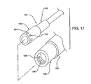
図17は、電気外科用器具および切除器具を組み合わせた複合装置におけるハンドピースおよびハブの別の形状を示しており、簡潔化のためハンドピース190の遠方端および、電気外科用器具および切除器具を組み合わせた複合装置191の近傍端のみが示されている。複合装置191の遠方端は、上記実施例のいずれかの形状でありうる。複合装置191は、ハブ193とともに外側の管状のハウジング要素192を備えており、このハブ193の内部には切除要素15が配置されている。ハブ193は、一つ以上の導電性スプリングの接点(すなわちブレード)194を一体化しており、この実施例においては、ハブ193の外表面の近傍端の部位に沿って外周的に配置されている。接点194は、ハウジング要素192の電極装置(ここには図示されていない。図25を参照)と電気的に接続している。ハンドピース190は、上記の口金32に類似する口金195を備えているが、これは口金195の内径に一つ以上の接点196を備えている。この実施態様における接点196は、ベリリウム銅のような耐蝕金属からなる。ハブ193の近傍端をハンドピース190の遠方端に挿入すると、複合装置191の接点194は口金194の接点196と位置が揃いこれと嵌合し、ケーブル16のようなケーブルの必要なしに電気エネルギーをハウジング要素192の電極装置に供給する。電気外科用器具および切除器具を組み合わせた複合装置191は、切除制御装置および無線周波制御装置を一体化した制御装置(ICC/RFC)によって制御されるか、個別の(ただし相互連結されている)切除制御装置および無線周波制御装置で制御される。
FIG. 17 illustrates another shape of the handpiece and hub in a combined device that combines an electrosurgical instrument and an ablation instrument, with the distal end of the
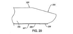
図18〜図20は、本発明の第7実施例であって、電気外科用器具および切除器具を組み合わせた複合装置200を示している。この複合装置200は、静止したハウジング管201を組み込んでおり、その中に切除要素15の回転する駆動軸69を収容している。この実施例におけるハウジング管201は、ステンレス鋼のような導電性金属からなり、その外表面にはパウダーコーティング法やその他の適切なコーティング方法で絶縁層202がコーティングされる。ハウジング管201は、上記のように絶縁層202とともに切断され、複合装置200の遠方端に窓部203が形成される。この切断工程により、絶縁層202より内方にハウジング管201の環状領域204が露出する。この環状領域204は、切除要素15の切除ヘッド71(ここでは図示せず)と協力して組織を切除する切除端205を有している。
18 to 20 show a
ハウジング管201は、絶縁層202上でハウジング管201に固定される電極装置207を設けている。この実施例における電極装置207は、ハウジング管201の外側の絶縁層202に沿って延長しており絶縁材で覆われた導電ワイヤすなわちストリップ状の電極要素208で構成される。この実施例における電極要素208は、ハブボア46の遠方部46A(図2)へと後方に延長しており、ケーブル16と電気的に接続している。別の実施態様においては、電極要素208は、図17に示すような複合装置200のハブに直接設けた接点を介して電力が供給される。さらに、電極装置207は、電極要素208と電気接触しているほぼ平坦で板状部材の活性電極209を備えている。この活性電極209は、活性電極を構成するよう絶縁されていない。この活性電極209は、ステンレス鋼やタングステンのような導電性金属からなる。ただし、その他の適切な物質を利用することもできる。
The
この実施例において、電極要素208および活性電極209は、溶接やその他の適切な方法で相互に連結しており、これらはハウジング管201の窓部203から離間する側でハウジング管201の絶縁層202に接着剤やその他の適切な固定方法によって固定されている。
In this embodiment, the
使用時には、活性電極209は目標の患者組織に電気エネルギーを伝達するために使用され、ハウジング管201の露出した環状領域204は、双極装置となるよう帰還電極として作用する。このとき、ハウジング管201は、ケーブル16(図1)に電気的に接続しているか、図17のような複合装置200のハブに接触して電力が供給される。
In use, the
図21〜図23は、本発明の第8実施例であって、電気外科用器具および切除器具を組み合わせた複合装置300を示している。この複合装置300は、図18〜図20の実施例と同様のものであるので、同一または類似の部品に対しては同一または類似の参照番号が用いられる。
21 to 23 show an eighth embodiment of the present invention, which is a
複合装置300は、絶縁層202でコーティングされており静止した導電性のハウジング管201を備えており、その中に回転する駆動軸69を収容している。このハウジング管201および絶縁層202は、その遠方端に窓部203を形成するよう切断され、それにより絶縁層202より内方にハウジング管201の環状領域204が露出する。この環状領域204は、切除ヘッド71と協力して組織を切除する切除端205を有している。ハウジング管201は、絶縁層202上でハウジング管201に固定される電極装置207を設けている。この実施例における電極装置307は、ハウジング管201の外側の絶縁層202に沿って延長しており絶縁材で覆われた導電ワイヤすなわちストリップ状の電極要素308で構成される。この実施例における電極要素308は、ハブボア46の遠方部46A(図2)へと後方に延長しており、ケーブル16と電気的に接続しているか、図17のように複合装置300のハブに設けた接点によって電力が供給される。さらに、電極装置307は、電極要素308と電気的に接触する薄い導電性要素309も備えている。この導電性要素309は、活性電極を構成するため絶縁されていない。この実施例においては、図18〜図20の実施例と同様に、電極装置307は、窓部203の反対側のハウジング管201に設けられている。しかし、活性電極209とは異なり、活性電極309は、ハウジング管201の遠方端に適合する形状になっており、また窓部203側に上方に小距離だけ延長している。活性電極309は、ステンレス鋼やタングステンのような導電性金属からなる。ただし、その他の適切な物質を用いることもできる。
The
この実施例において、電極要素308および活性電極309は、溶接やその他の適切な方法で相互連結しており、接着剤やその他の適切な方法で、窓部203の反対面側においてハウジング管201の絶縁層202に固着されている。
In this embodiment, the
使用時には、活性電極309は目標の患者組織に電気エネルギーを伝達するために使用され、ハウジング管201の露出した環状領域204は、双極装置となるよう帰還電極として作用する。
In use, the
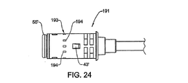
図24および図25は、図17に示すハンドピース190および複合装置191の詳細図である。ハンドピース190は図1および図2に示すハンドピース11と同様のものであるので、同一または類似の部品に対しては、参照番号に「’」を加えた参照番号を用いる。同様に、複合装置191は、図3に示す複合装置12と同様のものであるので、同一または類似の部品に対しては、参照番号に「’」を加えた参照番号を用いる。
24 and 25 are detailed views of the
図24および図25によると、図17に関して説明したように、複合装置191には、少なくとも一つ(ここでは複数)の導電性スプリングの接点(ブレード)194がハブ193の外周囲に設けられている。接点194は、配線401のような導電性要素を介して活性電極400と電気的に接続しているとともに(この活性電極400は、本明細書に開示される活性電極装置のいずれかでありうる)、配線403のような導電性要素を介してハウジング管402に接続している(このハウジング管402は、本明細書に開示される、帰還電極または共通の電極として使用されるハウジング管のいずれかでありうる)。ハブ193を延長する配線401、403は、図25では単に概略的に示されているだけであることは理解されよう。この点、接点194のいくつかは、電気エネルギーを活性電極400に供給するために使用され、その他の接点194は、ハウジング管402からの電気エネルギーを戻すために使用される。
24 and 25, as described with reference to FIG. 17, the
ハンドピース190に目を向けてみると、口金195には、少なくとも一つ(ここでは複数)の導電性の接点196が設けられている。この実施例における接点196は、口金195の内周囲に配置されている。これらの接点196は、ケーブル23(図1)および配線407、408を介して切除制御装置および無線周波制御装置を一体化した制御装置(ICC/RFC)と電気的に接続している。この配線407、408は、ハンドピース190の口金195およびハウジング18’を通している。接点196は、口金195に配置されるが、それが複合装置191の接点194と嵌合する位置に設けられることは理解されよう。そこで、嵌合した一対の接点194、196のいくつかは、「活性」接点として利用され、嵌合するその他の一対の接点194、196は、「戻り」接点として利用される。
Looking at the
このとき、接点194、196は、複合装置191および口金195のそれぞれに配置されるが、これら接点194、196が複合装置191の口金195およびハンドピース190に対する回転位置とは無関係に自動的に位置が揃い相互に嵌合するようになっている。より具体的には、複合装置191をハンドピース190に固定する口金195は、上記の口金32と同様のものであるが、この口金32は、複合装置191が二つの180度位置の一方で接続するように構成されている。この口金32の特徴については、譲受人の上記602出願公開に詳細に記載されているので、ここでは繰り返さない。さらに、接点194、195は、ハブとハンドピースとを電気的に接続できるよう適切に封止されることは理解されよう。様々な封止装置につき、以下説明する。
At this time, the
図17および図25に示されるハンドピース190は、それぞれ一つ以上の機能を有する様々な外科用器具とともに使用できることは理解されよう。より具体的には、ハンドピース190は、モータ20(図1)により駆動され、図26に示される外科用切除装置(シェーバ)500を駆動させる。外科用切除装置500は、ハブ40に類似するハブ502を備えた外側のハウジングアセンブリ501と、ハブ502から外側に突出しておりこのハブ502と連結した細長い外側管503とを備えている。この外側管503は、切除用の窓部504と、切除要素505が中に配置される内部管路とを有している。この切除要素505は、上記の切除要素15と同様のものである。外科用切除装置500をハンドピース190に取り付けると、モータ20の駆動軸21が切除要素505と駆動係合してこれを外側管503に対して回転させ、患者の組織を切除する。手術部位から流体およびその他の外科破片を除去するため、切除要素505を介して吸引物が引き込まれる。この種の外科用器具を使用する場合、ハンドピース190の口金195の電気的な接点196は使用されない。これは、この種の外科用器具は、オンボード部品への電力を必要としないからである。
It will be appreciated that the
さらに、接点196を一体化したハンドピース190は、図27に示す電気外科用器具510とともに使用可能である。この電気外科用装置510は、図24に示すハブ193と実質的に同一のハブ511を備えているので、同一または類似の部品に対しては、参照番号に「’」を付した番号を使用する。また、電気外科用装置510は、ハブ511から外側に突出するプローブ512を備えている。このプローブ512は、その中に内側の導電性のハウジング管513を備えている。このハウジング管513は、その全長の大部分は絶縁管すなわちシース514によって覆われている。ハウジング管513の一部は、その遠方端で露出しており、帰還電極515を構成する。活性電極装置516は、ハウジング管513内に設けられており、このハウジング管513の遠方開口端に着座する絶縁キャップすなわちスリーブ517を有している。この実施例においては、活性電極装置516は、その遠方端に複数の活性電極518を有している。電極装置516およびハウジング管513は、接点194’と電気的に接続している。吸引物がプローブ512およびハンドピース190を介して引き込まれるよう、内部空洞のハウジング管513は吸引管路519を有している。
Further, the
電気外科用装置510がハンドピース190に取り付けられると、接点194’はハンドピース190の遠方端に設けられた接点196と嵌合し、電力が電極装置516に供給されるとともにハンドピース190を介してハウジング管513に戻される。電気外科用装置510にはモータ20の駆動力を必要とする部品が設けられていないので、ハンドピース190の特徴事項はこの装置には用いられない。
When the
結合部材である口金195に設けられた接点194を組み込んだハンドピース190は、上記のような様々なタイプの外科用装置とともに使用可能な汎用ハンドピースとなり、一つのハンドピースは複合的な手術措置に使用可能となる。ここに記載される様々な手術用装置または器具は、全てハンドピース190との使用に適合しており、適切な装置を手術措置に応じて選択することができる。これらの器具は、一回使用毎に廃棄することができる。その他のタイプの外科用器具を上記の装置に加えてハンドピースに使用することも想定しているため、上記の記載は単に例示したにぎない。
The
図28および図29は、本発明に従い使用することができるハブとハンドピースとを連絡させる別の電気的接点装置を示している。図28に示される装置は、ハブ600を備えており、このハブ600は、中に複数のスプリングを組み込んだ電気的な接点601をその外周かつハブ600の遠方端の付近に有している。弾性のシール602は、ハブ600の周囲に設けられており、接点601をそれぞれ分離するとともに、ハブとハンドピースとの界面を封止する。この実施例においては、シール602は略H形状である。これら接点601は、これらに対応するよう口金604の内径に設けられた接点603と嵌合するよう配置される。
Figures 28 and 29 show another electrical contact device for communicating a hub and handpiece that can be used in accordance with the present invention. The apparatus shown in FIG. 28 includes a
図29に関しては、この装置は、複数(ここでは3つ)のシール(Oリング)611を有するハブ610を備えており、このシール611はハブ610の周囲を延長している。スプリングの接点612は、それぞれ近接する一対のシール611の間のハブ610上に設けられている。この接点612は、ハンドピースの口金614の内表面に設けられた導電性接点であるパッドまたはタブ613と嵌合する。口金の接点613は、ハブ610に設けられたシール611が接点間を封止するよう、またハブ610と口金614とを外環境から封止するよう、相互に軸方向で偏倚している。
With reference to FIG. 29, the apparatus includes a
図30は、一対のピン形状の接点621を有するハブ620を備えた装置を示している。この接点621は、ハブ620に固定される取付要素622を介して、ハブ620の遠方端の対向側に設けられている。この接点621は、ハンドピース623側である近傍側に突出している。ハンドピース623は、対応配置した一対の雌接点(栓受け)624をハンドピース623の口金625の遠方端に有している。この雌接点624は、ハンドピース623を通る配線すなわち導電要素627(点線で示されている)介して電源に電気的に接続している。あるいは、ピン形状の接点621をハンドピース623に設け、雌接点624をハブ620に設けることもできることは理解されよう。さらに、小さなOリングすなわちシール(ここでは図示されていない)は、近傍側すなわちハンドピース623側に面する取付要素622の側面においてピン形状の接点621の周囲に設け、ハブ620とハンドピース623との電気的界面(接合点)を封止することもできる。
FIG. 30 shows a device with a
図31は、シリコーンのような各シール652で包囲された複数のスプリング形状の接点651を有するハブ650を備えた装置を示している。接点651は、相互対向する位置に配置された一対の導電性の接点部材653により具体化されており、この接点部材653はシール652で包囲されている。接点651は、ハンドピース656の結合部材である口金655において対応配置した接点(すなわちブレード)654と嵌合する。この実施例においては、二対の接点651は、ハブ650上で正反対位置に設けられており、同様に二対の接点654も口金655内で接点651と対応した正反対位置に設けられている。ハブ650が口金655に挿入されると、口金655の接点654は、ハブ650の各接点651の一対の対向した接点部材653の間で軸方向に挿入される。
FIG. 31 shows a device with a
図32は、複数の接点671を設けたハブ670を一体化した装置を示している。この実施例においては、接点671は、ハンドピース673側へ近傍に開口する溝672を中に形成するよう略U字形状となっている。二対の接点671が反対位置でハブ670に設けられている。ハンドピースの結合部材すなわち口金674は、その中に複数の接点素子675を一体化している。この接点素子675は、それぞれ内方かつ遠方方向に開口した溝676を有している。ブレードすなわち雄接点677がそれぞれの溝676に設けられ、一対のシール678がそれぞれ溝676に面する対向面位置に設けられている。二対の接点675は、口金674内でその対向面に設けられ、これはハブ670の接点671と対応する位置である。ハブ670を口金674に挿入すると、雄接点677が対応する接点671の各溝672に挿入され、シール678がハブ670とハンドピース673との電気的界面を封止するよう作用する。
FIG. 32 shows an apparatus in which a
二つの部品間の電気的界面をもたらす上記のハブおよびハンドピースの装置によって、ハブおよび関連する外科用器具を容易にハンドピースに軸方向挿入できるようになるとともに、この界面を封止するようになる。その他のタイプの電気的界面(接合点)も、それが頑丈かつ確実に二つの部品間の電気的接続をもたらす限り、これを用いることができることは理解されよう。 The hub and handpiece device described above, which provides an electrical interface between the two parts, allows the hub and associated surgical instruments to be easily inserted axially into the handpiece and seals this interface. Become. It will be appreciated that other types of electrical interfaces (junctions) can be used as long as it provides a robust and reliable electrical connection between the two parts.
この結果、既知の装置の欠点をなくすか少なくとも最小限にするため、本発明による外科用器具装置10は、電動ハンドピース11に取り外し可能に装着する最少サイズの一体化器具を提供するものであるが、対象組織にエネルギー伝達する回転部品を使用しないものであって、機械的切除界面におけるエネルギー伝達を改良する表面領域が小さな静止ハウジングに活性電極を設けているものである。より具体的には、本発明の外科用器具装置は、外側ハウジング要素13と、このハウジング要素13に固定したカニューレすなわちシースとを備えており、この外側ハウジング要素13は、ハンドピース11の結合装置に取り付けるハブ装置を有しており、この中に可動切除要素が配置される。このカニューレの遠方端には、切除要素の切除ヘッドを露出させるよう、開口部すなわち窓部を有している。電気エネルギーはカニューレに設けた電極装置に供給されるとともに、電極は切除界面の窓部の直ぐ近傍に設けられる。電気エネルギーは、接地パッドかカニューレの導電部を介して戻る。
即ち、この発明においては、電気外科用器具および機械的切除器具を組み合わせた複合切除装置12と協力する電動ハンドピース11を有する外科用器具装置10を提供する。複合切除装置12は、手術部位に電気エネルギーを伝達する電極を備えた静止した外側ハウジング要素13を有しており、またこの外側ハウジング13内には患者組織を処理するよう相対的に可動な切除要素を収容している。前記複合切除装置は、単独装置で複数の機能(焼灼、アブレーション、および機械的切除等)を有するようにして外科用装置に装着可能となった一体的な部品であるので、追加ハウジング構造やその他のアダプタを装着する必要がなくなる。また外科用器具装置は、それぞれ一つ以上の機能を有する様々な外科用装置を取り付けて操作可能な汎用ハンドピースを備えている。
As a result, in order to eliminate or at least minimize the disadvantages of known devices, the
In other words, the present invention provides a
なお、上記の各実施例においては、所定の用語が以下の記述で使用されるが、これは便宜上のものであって、これに限定されるものではない。例えば、「上方に」、「下方に」、「左に」、「右に」という用語は、参照している図面を基準とした方向を指している。「内側に」、「外側に」という用語は、装置や指摘した部品の中央側へまたは中央から離れる方向を指している。「前方に」、「遠方に」という用語は、装置の患者に最も近い側を指しており、また「後方に」、「近傍に」という用語は、装置の患者に最も遠い側を指している。このような用語は、具体的に言及された語や、派生語や同様の意味を有する語が含まれる。 In each of the above embodiments, a predetermined term is used in the following description, but this is for convenience and is not limited thereto. For example, the terms “upward”, “downward”, “leftward”, and “rightward” refer to directions relative to the referenced drawing. The terms “inside” and “outside” refer to a direction toward or away from the center of the device or indicated part. The terms “forward” and “distant” refer to the side of the device closest to the patient, and the terms “backward” and “near” refer to the side of the device farthest from the patient. . Such terms include words specifically mentioned, derivatives and words having similar meanings.
本発明において、各実施例を例示として詳細に開示したが、開示された装置の変形、変更、または部品の再構成は、本発明の範囲内にあると理解されよう。 While each embodiment has been disclosed in detail in the present invention by way of example, it will be understood that variations, modifications, or reconfigurations of the disclosed apparatus are within the scope of the invention.
10 外科用器具装置
11 ハンドピース
12 複合切除装置
13 ハウジング要素
14 電極装置
15 切除要素
16 ケーブル
18 ハンドピースハウジング
19 ハウジングボア
20 モータ
21 駆動軸
22 駆動ピン
23 電力ケーブル
DESCRIPTION OF
Claims (4)
前記ハンドピース(190、623、656、673)は、近傍端とこの近傍端から離間した遠方端とを有するハウジング(18’)と、前記ハウジング(18’)に配置され、身体組織を切断する第1外科用装置(12、100、110、120、140、160、191、200、300、500)の可動機械的な切除要素(15、505)を駆動するために配置された出力軸(21)を有するモータ(20)とを含み、
前記第1外科用装置(12、100、110、120、140、160、191、200、300、500)は、第1ハブ(193、502、600、610、620、650、670)を有し、
前記ハンドピース(190、623、656、673)は、前記ハウジング(18’)の遠方端に配置され、前記ハウジング(18’)を介して電力源(ICC/RFC)に近傍で接続された一体的で電気的な第1接点部材(196、603、613、624、654、675)を前記ハウジング(18’)の遠方端に画定する結合部材(195、604、614、625、655、674)を含み、
前記第1外科用装置(12、100、110、120、140、160、191、200、300、500)と区別できる第2外科用装置(12、100、110、120、140、160、191、200、300、510)を備え、
この第2外科用装置(12、100、110、120、140、160、191、200、300、510)は、患者組織を電気的に処理する電極装置(14、104、117、129、146、163、207、307、516)が組み込まれる第2ハブ(193、511、600、610、620、650、670)を有し、
前記第2ハブ(193、511、600、610、620、650、670)には、前記第1接点部材(196、603、613、624、654、675)に対応し、前記第1接点部材(196、603、613、624、654、675)と一体化する電気的な第2接点部材(194、194’、601、612、621、651、671)を配置し、
前記結合部材(195、604、614、625、655、674)は、前記第1外科用装置(12、100、110、120、140、160、191、200、300、500)及び前記第2外科用装置(12、100、110、120、140、160、191、200、300、510)のうちの対応する一方を前記ハンドピース(190、623、656、673)に固定的、かつ、取り外し可能に固定するために、前記第1ハブ(193、502、600、610、620、650、670)又は前記第2ハブ(193、511、600、610、620、650、670)のうちのいずれかに取り外し可能に装着するために構成されていることを特徴とする外科用器具装置。A surgical instrument device (10) comprising a handpiece (190, 623, 656, 673) comprising:
The handpiece (190, 623, 656, 673) is disposed in the housing (18 ') having a proximal end and a distal end spaced from the proximal end, and cuts the body tissue. An output shaft (21) arranged to drive the movable mechanical ablation element (15, 505) of the first surgical device (12, 100, 110, 120, 140, 160, 191, 200, 300, 500) And a motor (20) having
The first surgical device (12, 100, 110, 120, 140, 160, 191, 200, 300, 500) has a first hub (193, 502, 600, 610, 620, 650, 670). ,
The handpiece (190, 623, 656, 673) is disposed at the far end of the housing (18 ′) and is connected to the power source (ICC / RFC) in the vicinity via the housing (18 ′). Coupling members (195, 604, 614, 625, 655, 674) that define first electrical contacts (196, 603, 613, 624, 654, 675) at the distal end of the housing (18 '). Including
A second surgical device (12, 100, 110, 120, 140, 160, 191, distinguishable from the first surgical device (12, 100, 110, 120, 140, 160, 191, 200, 300, 500)) 200, 300, 510)
This second surgical device (12, 100, 110, 120, 140, 160, 191, 200, 300, 510) is an electrode device (14, 104, 117, 129, 146, electrically treating patient tissue). 163, 207, 307, 516) having a second hub (193, 511, 600, 610, 620, 650, 670) into which
The second hub (193, 511, 600, 610, 620, 650, 670) corresponds to the first contact member (196, 603, 613, 624, 654, 675), and the first contact member ( 196, 603, 613, 624, 654, 675) and an electrical second contact member (194, 194 ′, 601, 612, 621, 651, 671),
The coupling member (195, 604, 614, 625, 655, 674) is connected to the first surgical device (12, 100, 110, 120, 140, 160, 191, 200, 300, 500) and the second surgical device. Corresponding one of the devices (12, 100, 110, 120, 140, 160, 191, 200, 300, 510) is fixed to the handpiece (190, 623, 656, 673) and removable. One of the first hub (193, 502, 600, 610, 620, 650, 670) or the second hub (193, 511, 600, 610, 620, 650, 670) A surgical instrument device configured to be removably mounted on a surgical instrument.
前記第1ハブ(193、502、600、610、620、650、670)は、前記外側静止ハウジングアセンブリ(501)の近傍端を画定し、
前記第1ハブ(193、502、600、610、620、650、670)は、前記ハンドピース(190、623、656、673)の前記結合部材(195、604、614、625、655、674)と連動係合するため構成された取付用構成体(43、43’)を画定し、
ハウジング部材(59、101/102、111/112、121/123/124/125、141/142、161/162、192、201/202、503)は、前記第1ハブ(193、502、600、610、620、650、670)に接続され、前記ハウジング部材(59、101/102、111/112、121/123/124/125、141/142、161/162、192、201/202、503)の遠方端に窓部(72、82、103、114、127、143、169、203、504)を画定し、
前記切除要素(15、505)は、前記第1外科用装置(12、100、110、120、140、160、191、200、300、500)の前記外側静止ハウジングアセンブリ(501)の内部に可動的に配置され、前記モータ(20)の前記出力軸(21)に連結され、前記出力軸(21)によって駆動される第3ハブ(61)を含み、細長い駆動軸(69)が前記第3ハブ(61)に接続され、前記駆動軸(69)の遠方端に切除ヘッド(71)を画定し、
前記切除ヘッド(71)は、目標患者組織を切断するために前記窓部(72、82、103、114、127、143、169、203、504)に隣接して配置されていることを特徴とする請求項1に記載の外科用器具装置。The first surgical device (12, 100, 110, 120, 140, 160, 191, 200, 300, 500) includes an outer stationary housing assembly (501);
The first hub (193, 502, 600, 610, 620, 650, 670) defines a proximal end of the outer stationary housing assembly (501);
The first hub (193, 502, 600, 610, 620, 650, 670) is connected to the coupling member (195, 604, 614, 625, 655, 674) of the handpiece (190, 623, 656, 673). Defining mounting structures (43, 43 ') configured for interlocking engagement with
Housing members (59, 101/102, 111/112, 121/123/124/125, 141/142, 161/162, 192, 201/202, 503) are connected to the first hub (193, 502, 600, 610, 620, 650, 670) and the housing member (59, 101/102, 111/112, 121/123/124/125, 141/142, 161/162, 192, 201/202, 503) A window (72, 82, 103, 114, 127, 143, 169, 203, 504) at the far end of the
The ablation element (15, 505) is movable within the outer stationary housing assembly (501) of the first surgical device (12, 100, 110, 120, 140, 160, 191, 200, 300, 500). And a third hub (61) connected to the output shaft (21) of the motor (20) and driven by the output shaft (21), an elongated drive shaft (69) being the third Connected to the hub (61) and defining a cutting head (71) at the distal end of the drive shaft (69);
The ablation head (71) is disposed adjacent to the windows (72, 82, 103, 114, 127, 143, 169, 203, 504) to cut target patient tissue. The surgical instrument apparatus according to claim 1.
前記第2ハブ(193、511、600、610、620、650、670)は、前記ハンドピース(190、623、656、673)の前記結合部材(195、604、614、625、655、674)と連動係合するため構成された取付用構成体(43、43’、43”)を画定し、
ハウジング部材(59、101/102、111/112、121/123/124/125、141/142、161/162、192、201/202、512)が前記第2ハブ(193、511、600、610、620、650、670)に接続され、患者組織を電気的に処理する前記電極装置(14、104、117、129、146、163、207、307、516)を前記ハウジング部材(59、101/102、111/112、121/123/124/125、141/142、161/162、192、201/202、512)の遠方端に搭載し、
前記第2ハブ(193、511、600、610、620、650、670)は、前記電極装置(14、104、117、129、146、163、207、307、516)に電気的に接続された前記第2接点部材(194、194’、601、612、621、651、671)を画定し、
前記第2ハブ(193、511、600、610、620、650、670)の前記第2接点部材(194、194’、601、612、621、651、671)は、電力を前記電極装置(14、104、117、129、146、163、207、307、516)に供給するため、前記ハンドピース(190、623、656、673)への前記第2外科用装置(12、100、110、120、140、160、191、200、300、510)の装着時に前記ハンドピース(190、623、656、673)の前記結合部材(195、604、614、625、655、674)の前記第1接点部材(196、603、613、624、654、675)と一体化することを特徴とする請求項1に記載の外科用器具装置。The second hub (193, 511, 600, 610, 620, 650, 670) of the second surgical device (12, 100, 110, 120, 140, 160, 191, 200, 300, 510) Defining the proximal end of the second surgical device (12, 100, 110, 120, 140, 160, 191, 200, 300, 510);
The second hub (193, 511, 600, 610, 620, 650, 670) is connected to the coupling member (195, 604, 614, 625, 655, 674) of the handpiece (190, 623, 656, 673). Defining mounting structures (43, 43 ', 43 ") configured for interlocking engagement with
Housing members (59, 101/102, 111/112, 121/123/124/125, 141/142, 161/162, 192, 201/202, 512) are connected to the second hub (193, 511, 600, 610). , 620, 650, 670) and the electrode device (14, 104, 117, 129, 146, 163, 207, 307, 516) for electrically processing patient tissue is connected to the housing member (59, 101 / 102, 111/112, 121/123/124/125, 141/142, 161/162, 192, 201/202, 512)
The second hub (193, 511, 600, 610, 620, 650, 670) was electrically connected to the electrode device (14, 104, 117, 129, 146, 163, 207, 307, 516). Defining the second contact member (194, 194 ′, 601, 612, 621, 651, 671);
The second contact members (194, 194 ′, 601, 612, 621, 651, 671) of the second hub (193, 511, 600, 610, 620, 650, 670) supply power to the electrode device (14). 104, 117, 129, 146, 163, 207, 307, 516), the second surgical device (12, 100, 110, 120) to the handpiece (190, 623, 656, 673). 140, 160, 191, 200, 300, 510) when the first contact point of the coupling member (195, 604, 614, 625, 655, 674) of the handpiece (190, 623, 656, 673) is mounted. Surgical instrument device according to claim 1, characterized in that it is integral with the member (196, 603, 613, 624, 654, 675).
前記第1ハブ(193、600、610、620、650、670)は、前記外側静止ハウジングアセンブリ(501)の近傍端を画定し、
前記第1ハブ(193、600、610、620、650、670)は、前記ハンドピース(190、623、656、673)の前記結合部材(195、604、614、625、655、674)と連動係合するため構成された取付用構成体(43、43’)を画定し、
ハウジング部材(59、101/102、111/112、121/123/124/125、141/142、161/162、192、201/202)が前記第1ハブ(193、600、610、620、650、670)に接続され、前記ハウジング部材(59、101/102、111/112、121/123/124/125、141/142、161/162、192、201/202)の遠方端に窓部(72、82、103、114、127、143、169、203)を画定し、
前記電極装置(14、104、117、129、146、163、207、307)が前記ハウジング部材(59、101/102、111/112、121/123/124/125、141/142、161/162、192、201/202)に搭載され、前記窓部(72、82、103、114、127、143、169、203)に隣接して配置されて患者組織を電気的に処理する電極装置(14、104、117、129、146、163、207、307)を画定し、
前記第1ハブ(193、600、610、620、650、670)は、電力を供給するために前記電極装置(14、104、117、129、146、163、207、307)に接続された前記第2接点部材(194、601、612、621、651、671)を画定し、
前記第2接点部材(194、601、612、621、651、671)は、前記ハンドピース(190、623、656、673)への前記第1外科用装置(12、100、110、120、140、160、191、200、300)の装着時に前記ハンドピース(190、623、656、673)の前記結合部材(195、604、614、625、655、674)の前記第1接点部材(196、603、613、624、654、675)と一体化し、
前記第1外科用装置(12、100、110、120、140、160、191、200、300)は、前記外側静止ハウジングアセンブリ(501)の内部に可動的に配置され、前記モータ(20)の前記出力軸(21)に連結され、前記出力軸(21)によって駆動されるために構成された第3ハブ(61)を有する前記切除要素(15)を含み、細長い駆動軸(69)が前記第3ハブ(61)に接続され、前記ハウジング部材(59、101/102、111/112、121/123/124/125、141/142、161/162、192、201/202)の遠方端に切除ヘッド(71)を画定し、
前記切除ヘッド(71)は、患者組織を切断するために前記窓部(82、103、114、127、143、169、203)に隣接して配置されていることを特徴とする請求項1に記載の外科用器具装置。The first surgical device (12, 100, 110, 120, 140, 160, 191, 200, 300) includes an outer stationary housing assembly (501);
The first hub (193, 600, 610, 620, 650, 670) defines a proximal end of the outer stationary housing assembly (501);
The first hub (193, 600, 610, 620, 650, 670) is interlocked with the coupling member (195, 604, 614, 625, 655, 674) of the handpiece (190, 623, 656, 673). Defining mounting structures (43, 43 ') configured for engagement;
Housing members (59, 101/102, 111/112, 121/123/124/125, 141/142, 161/162, 192, 201/202) are connected to the first hub (193, 600, 610, 620, 650). , 670), and a window portion (59, 101/102, 111/112, 121/123/124/125, 141/142, 161/162, 192, 201/202) at the far end of the housing member (59, 101/102, 111/112, 121/123/124/125) 72, 82, 103, 114, 127, 143, 169, 203),
The electrode device (14, 104, 117, 129, 146, 163, 207, 307) is connected to the housing member (59, 101/102, 111/112, 121/123/124/125, 141/142, 161/162). 192, 201/202) and disposed adjacent to the window (72, 82, 103, 114, 127, 143, 169, 203) to electrically process patient tissue (14 104, 117, 129, 146, 163, 207, 307),
The first hub (193, 600, 610, 620, 650, 670) is connected to the electrode device (14, 104, 117, 129, 146, 163, 207, 307) to supply power. Defining second contact members (194, 601, 612, 621, 651, 671);
The second contact member (194, 601, 612, 621, 651, 671) is connected to the first surgical device (12, 100, 110, 120, 140) to the handpiece (190, 623, 656, 673). , 160, 191, 200, 300) when the first contact member (196, 604, 614, 625, 655, 674) of the handpiece (190, 623, 656, 673) is attached. 603, 613, 624, 654, 675)
The first surgical device (12, 100, 110, 120, 140, 160, 191, 200, 300) is movably disposed within the outer stationary housing assembly (501) and of the motor (20). Including an ablation element (15) coupled to the output shaft (21) and having a third hub (61) configured to be driven by the output shaft (21), wherein an elongated drive shaft (69) Connected to the third hub (61) and at the far end of the housing member (59, 101/102, 111/112, 121/123/124/125, 141/142, 161/162, 192, 201/202) Defining an ablation head (71);
2. The ablation head (71) is disposed adjacent to the window (82, 103, 114, 127, 143, 169, 203) for cutting patient tissue. The surgical instrument device as described.
Applications Claiming Priority (3)
| Application Number | Priority Date | Filing Date | Title |
|---|---|---|---|
| US66273505P | 2005-03-17 | 2005-03-17 | |
| US60/662,735 | 2005-03-17 | ||
| PCT/US2006/009802 WO2006102124A2 (en) | 2005-03-17 | 2006-03-17 | Surgical tool arrangement |
Publications (2)
| Publication Number | Publication Date |
|---|---|
| JP2008532712A JP2008532712A (en) | 2008-08-21 |
| JP5090334B2 true JP5090334B2 (en) | 2012-12-05 |
Family
ID=36693964
Family Applications (1)
| Application Number | Title | Priority Date | Filing Date |
|---|---|---|---|
| JP2008502112A Expired - Fee Related JP5090334B2 (en) | 2005-03-17 | 2006-03-17 | Surgical instrument device |
Country Status (5)
| Country | Link |
|---|---|
| US (1) | US9504521B2 (en) |
| EP (1) | EP1885258A2 (en) |
| JP (1) | JP5090334B2 (en) |
| CA (1) | CA2601626C (en) |
| WO (1) | WO2006102124A2 (en) |
Families Citing this family (481)
| Publication number | Priority date | Publication date | Assignee | Title |
|---|---|---|---|---|
| US9060770B2 (en) | 2003-05-20 | 2015-06-23 | Ethicon Endo-Surgery, Inc. | Robotically-driven surgical instrument with E-beam driver |
| US20070084897A1 (en) | 2003-05-20 | 2007-04-19 | Shelton Frederick E Iv | Articulating surgical stapling instrument incorporating a two-piece e-beam firing mechanism |
| DE10327237A1 (en) * | 2003-06-17 | 2005-01-13 | Trumpf Medizin Systeme Gmbh + Co. Kg | Electrosurgical instrument for an endoscope |
| US8215531B2 (en) | 2004-07-28 | 2012-07-10 | Ethicon Endo-Surgery, Inc. | Surgical stapling instrument having a medical substance dispenser |
| US11896225B2 (en) | 2004-07-28 | 2024-02-13 | Cilag Gmbh International | Staple cartridge comprising a pan |
| JP5090334B2 (en) | 2005-03-17 | 2012-12-05 | ストライカー コーポレーション | Surgical instrument device |
| US11246590B2 (en) | 2005-08-31 | 2022-02-15 | Cilag Gmbh International | Staple cartridge including staple drivers having different unfired heights |
| US9237891B2 (en) | 2005-08-31 | 2016-01-19 | Ethicon Endo-Surgery, Inc. | Robotically-controlled surgical stapling devices that produce formed staples having different lengths |
| US7669746B2 (en) | 2005-08-31 | 2010-03-02 | Ethicon Endo-Surgery, Inc. | Staple cartridges for forming staples having differing formed staple heights |
| US11484312B2 (en) | 2005-08-31 | 2022-11-01 | Cilag Gmbh International | Staple cartridge comprising a staple driver arrangement |
| US10159482B2 (en) | 2005-08-31 | 2018-12-25 | Ethicon Llc | Fastener cartridge assembly comprising a fixed anvil and different staple heights |
| US7934630B2 (en) | 2005-08-31 | 2011-05-03 | Ethicon Endo-Surgery, Inc. | Staple cartridges for forming staples having differing formed staple heights |
| US20070106317A1 (en) | 2005-11-09 | 2007-05-10 | Shelton Frederick E Iv | Hydraulically and electrically actuated articulation joints for surgical instruments |
| US20110024477A1 (en) | 2009-02-06 | 2011-02-03 | Hall Steven G | Driven Surgical Stapler Improvements |
| US7845537B2 (en) | 2006-01-31 | 2010-12-07 | Ethicon Endo-Surgery, Inc. | Surgical instrument having recording capabilities |
| US11793518B2 (en) | 2006-01-31 | 2023-10-24 | Cilag Gmbh International | Powered surgical instruments with firing system lockout arrangements |
| US20110295295A1 (en) | 2006-01-31 | 2011-12-01 | Ethicon Endo-Surgery, Inc. | Robotically-controlled surgical instrument having recording capabilities |
| US20120292367A1 (en) | 2006-01-31 | 2012-11-22 | Ethicon Endo-Surgery, Inc. | Robotically-controlled end effector |
| US11224427B2 (en) | 2006-01-31 | 2022-01-18 | Cilag Gmbh International | Surgical stapling system including a console and retraction assembly |
| US8820603B2 (en) | 2006-01-31 | 2014-09-02 | Ethicon Endo-Surgery, Inc. | Accessing data stored in a memory of a surgical instrument |
| US8708213B2 (en) | 2006-01-31 | 2014-04-29 | Ethicon Endo-Surgery, Inc. | Surgical instrument having a feedback system |
| US8186555B2 (en) | 2006-01-31 | 2012-05-29 | Ethicon Endo-Surgery, Inc. | Motor-driven surgical cutting and fastening instrument with mechanical closure system |
| US7753904B2 (en) | 2006-01-31 | 2010-07-13 | Ethicon Endo-Surgery, Inc. | Endoscopic surgical instrument with a handle that can articulate with respect to the shaft |
| US11278279B2 (en) | 2006-01-31 | 2022-03-22 | Cilag Gmbh International | Surgical instrument assembly |
| US8992422B2 (en) | 2006-03-23 | 2015-03-31 | Ethicon Endo-Surgery, Inc. | Robotically-controlled endoscopic accessory channel |
| EP2015698B1 (en) | 2006-04-20 | 2017-11-15 | Sonendo, Inc. | Apparatus for treating root canals of teeth |
| US10835355B2 (en) | 2006-04-20 | 2020-11-17 | Sonendo, Inc. | Apparatus and methods for treating root canals of teeth |
| US8322455B2 (en) | 2006-06-27 | 2012-12-04 | Ethicon Endo-Surgery, Inc. | Manually driven surgical cutting and fastening instrument |
| US7980854B2 (en) | 2006-08-24 | 2011-07-19 | Medical Dental Advanced Technologies Group, L.L.C. | Dental and medical treatments and procedures |
| US10568652B2 (en) | 2006-09-29 | 2020-02-25 | Ethicon Llc | Surgical staples having attached drivers of different heights and stapling instruments for deploying the same |
| US7506791B2 (en) | 2006-09-29 | 2009-03-24 | Ethicon Endo-Surgery, Inc. | Surgical stapling instrument with mechanical mechanism for limiting maximum tissue compression |
| US8684253B2 (en) | 2007-01-10 | 2014-04-01 | Ethicon Endo-Surgery, Inc. | Surgical instrument with wireless communication between a control unit of a robotic system and remote sensor |
| US11291441B2 (en) | 2007-01-10 | 2022-04-05 | Cilag Gmbh International | Surgical instrument with wireless communication between control unit and remote sensor |
| US8652120B2 (en) | 2007-01-10 | 2014-02-18 | Ethicon Endo-Surgery, Inc. | Surgical instrument with wireless communication between control unit and sensor transponders |
| US11039836B2 (en) | 2007-01-11 | 2021-06-22 | Cilag Gmbh International | Staple cartridge for use with a surgical stapling instrument |
| US8701958B2 (en) | 2007-01-11 | 2014-04-22 | Ethicon Endo-Surgery, Inc. | Curved end effector for a surgical stapling device |
| US7669747B2 (en) | 2007-03-15 | 2010-03-02 | Ethicon Endo-Surgery, Inc. | Washer for use with a surgical stapling instrument |
| US8893946B2 (en) | 2007-03-28 | 2014-11-25 | Ethicon Endo-Surgery, Inc. | Laparoscopic tissue thickness and clamp load measuring devices |
| US8931682B2 (en) | 2007-06-04 | 2015-01-13 | Ethicon Endo-Surgery, Inc. | Robotically-controlled shaft based rotary drive systems for surgical instruments |
| US11564682B2 (en) | 2007-06-04 | 2023-01-31 | Cilag Gmbh International | Surgical stapler device |
| US7753245B2 (en) | 2007-06-22 | 2010-07-13 | Ethicon Endo-Surgery, Inc. | Surgical stapling instruments |
| US11849941B2 (en) | 2007-06-29 | 2023-12-26 | Cilag Gmbh International | Staple cartridge having staple cavities extending at a transverse angle relative to a longitudinal cartridge axis |
| DE102008006880A1 (en) * | 2008-01-31 | 2009-08-06 | Karl Storz Gmbh & Co. Kg | Bipolar coagulation instrument |
| JP5410110B2 (en) | 2008-02-14 | 2014-02-05 | エシコン・エンド−サージェリィ・インコーポレイテッド | Surgical cutting / fixing instrument with RF electrode |
| US7819298B2 (en) | 2008-02-14 | 2010-10-26 | Ethicon Endo-Surgery, Inc. | Surgical stapling apparatus with control features operable with one hand |
| US9179912B2 (en) | 2008-02-14 | 2015-11-10 | Ethicon Endo-Surgery, Inc. | Robotically-controlled motorized surgical cutting and fastening instrument |
| US8636736B2 (en) | 2008-02-14 | 2014-01-28 | Ethicon Endo-Surgery, Inc. | Motorized surgical cutting and fastening instrument |
| US8573465B2 (en) | 2008-02-14 | 2013-11-05 | Ethicon Endo-Surgery, Inc. | Robotically-controlled surgical end effector system with rotary actuated closure systems |
| US7866527B2 (en) | 2008-02-14 | 2011-01-11 | Ethicon Endo-Surgery, Inc. | Surgical stapling apparatus with interlockable firing system |
| US8758391B2 (en) | 2008-02-14 | 2014-06-24 | Ethicon Endo-Surgery, Inc. | Interchangeable tools for surgical instruments |
| US11272927B2 (en) | 2008-02-15 | 2022-03-15 | Cilag Gmbh International | Layer arrangements for surgical staple cartridges |
| US20130153641A1 (en) | 2008-02-15 | 2013-06-20 | Ethicon Endo-Surgery, Inc. | Releasable layer of material and surgical end effector having the same |
| ES2428719T3 (en) | 2008-03-31 | 2013-11-11 | Applied Medical Resources Corporation | Electrosurgical system with means to measure tissue permittivity and conductivity |
| US9005230B2 (en) | 2008-09-23 | 2015-04-14 | Ethicon Endo-Surgery, Inc. | Motorized surgical instrument |
| US11648005B2 (en) | 2008-09-23 | 2023-05-16 | Cilag Gmbh International | Robotically-controlled motorized surgical instrument with an end effector |
| US8210411B2 (en) | 2008-09-23 | 2012-07-03 | Ethicon Endo-Surgery, Inc. | Motor-driven surgical cutting instrument |
| US9386983B2 (en) | 2008-09-23 | 2016-07-12 | Ethicon Endo-Surgery, Llc | Robotically-controlled motorized surgical instrument |
| US8608045B2 (en) | 2008-10-10 | 2013-12-17 | Ethicon Endo-Sugery, Inc. | Powered surgical cutting and stapling apparatus with manually retractable firing system |
| US8517239B2 (en) | 2009-02-05 | 2013-08-27 | Ethicon Endo-Surgery, Inc. | Surgical stapling instrument comprising a magnetic element driver |
| US8444036B2 (en) | 2009-02-06 | 2013-05-21 | Ethicon Endo-Surgery, Inc. | Motor driven surgical fastener device with mechanisms for adjusting a tissue gap within the end effector |
| EP2393430A1 (en) | 2009-02-06 | 2011-12-14 | Ethicon Endo-Surgery, Inc. | Driven surgical stapler improvements |
| ES2664129T3 (en) * | 2009-02-26 | 2018-04-18 | Stryker Corporation | Surgical tool arrangement that has a usable handpiece with multiple surgical tools |
| US8435259B2 (en) | 2009-05-19 | 2013-05-07 | Stryker Corporation | Surgical tool arrangement and surgical cutting accessory for use therewith with the tool arrangement including a toothed cutting edge and a generally straight cutting edge |
| US10299855B2 (en) | 2009-06-16 | 2019-05-28 | Karl Storz Se & Co. Kg | Medical coagulation instrument |
| CA2780800C (en) | 2009-11-13 | 2023-09-12 | Sonendo, Inc. | Liquid jet apparatus and methods for dental treatments |
| DE202009017470U1 (en) * | 2009-12-23 | 2011-02-10 | Joimax Gmbh | Surgical instrument for releasably connecting a handpiece with a surgical tool |
| US8851354B2 (en) | 2009-12-24 | 2014-10-07 | Ethicon Endo-Surgery, Inc. | Surgical cutting instrument that analyzes tissue thickness |
| US8220688B2 (en) | 2009-12-24 | 2012-07-17 | Ethicon Endo-Surgery, Inc. | Motor-driven surgical cutting instrument with electric actuator directional control assembly |
| US8783543B2 (en) | 2010-07-30 | 2014-07-22 | Ethicon Endo-Surgery, Inc. | Tissue acquisition arrangements and methods for surgical stapling devices |
| US10945731B2 (en) | 2010-09-30 | 2021-03-16 | Ethicon Llc | Tissue thickness compensator comprising controlled release and expansion |
| US9629814B2 (en) | 2010-09-30 | 2017-04-25 | Ethicon Endo-Surgery, Llc | Tissue thickness compensator configured to redistribute compressive forces |
| US9566061B2 (en) | 2010-09-30 | 2017-02-14 | Ethicon Endo-Surgery, Llc | Fastener cartridge comprising a releasably attached tissue thickness compensator |
| US11849952B2 (en) | 2010-09-30 | 2023-12-26 | Cilag Gmbh International | Staple cartridge comprising staples positioned within a compressible portion thereof |
| US11298125B2 (en) | 2010-09-30 | 2022-04-12 | Cilag Gmbh International | Tissue stapler having a thickness compensator |
| US11812965B2 (en) | 2010-09-30 | 2023-11-14 | Cilag Gmbh International | Layer of material for a surgical end effector |
| US9364233B2 (en) | 2010-09-30 | 2016-06-14 | Ethicon Endo-Surgery, Llc | Tissue thickness compensators for circular surgical staplers |
| US8746535B2 (en) | 2010-09-30 | 2014-06-10 | Ethicon Endo-Surgery, Inc. | Tissue thickness compensator comprising detachable portions |
| US9839420B2 (en) | 2010-09-30 | 2017-12-12 | Ethicon Llc | Tissue thickness compensator comprising at least one medicament |
| US9517063B2 (en) | 2012-03-28 | 2016-12-13 | Ethicon Endo-Surgery, Llc | Movable member for use with a tissue thickness compensator |
| US9386988B2 (en) | 2010-09-30 | 2016-07-12 | Ethicon End-Surgery, LLC | Retainer assembly including a tissue thickness compensator |
| US8695866B2 (en) | 2010-10-01 | 2014-04-15 | Ethicon Endo-Surgery, Inc. | Surgical instrument having a power control circuit |
| EP3332723B1 (en) | 2010-10-01 | 2022-02-16 | Applied Medical Resources Corporation | Electrosurgical instruments and connections thereto |
| AU2011316839B2 (en) | 2010-10-21 | 2015-04-23 | Sonendo, Inc. | Apparatus, methods, and compositions for endodontic treatments |
| US9308013B2 (en) * | 2010-11-03 | 2016-04-12 | Gyrus Ent, L.L.C. | Surgical tool with sheath |
| AU2011328926B2 (en) * | 2010-11-16 | 2015-07-09 | Tva Medical, Inc. | Devices and methods for forming a fistula |
| AU2012250197B2 (en) | 2011-04-29 | 2017-08-10 | Ethicon Endo-Surgery, Inc. | Staple cartridge comprising staples positioned within a compressible portion thereof |
| US9072535B2 (en) | 2011-05-27 | 2015-07-07 | Ethicon Endo-Surgery, Inc. | Surgical stapling instruments with rotatable staple deployment arrangements |
| US11207064B2 (en) | 2011-05-27 | 2021-12-28 | Cilag Gmbh International | Automated end effector component reloading system for use with a robotic system |
| US20130046299A1 (en) * | 2011-08-18 | 2013-02-21 | John J. Newkirk | Intelligent electrosurgical electrode and tracking system |
| US8870864B2 (en) | 2011-10-28 | 2014-10-28 | Medtronic Advanced Energy Llc | Single instrument electrosurgery apparatus and its method of use |
| US9044230B2 (en) | 2012-02-13 | 2015-06-02 | Ethicon Endo-Surgery, Inc. | Surgical cutting and fastening instrument with apparatus for determining cartridge and firing motion status |
| AU2013235347B2 (en) | 2012-03-22 | 2017-11-09 | Sonendo, Inc. | Apparatus and methods for cleaning teeth |
| RU2639857C2 (en) | 2012-03-28 | 2017-12-22 | Этикон Эндо-Серджери, Инк. | Tissue thickness compensator containing capsule for medium with low pressure |
| MX358135B (en) | 2012-03-28 | 2018-08-06 | Ethicon Endo Surgery Inc | Tissue thickness compensator comprising a plurality of layers. |
| RU2644272C2 (en) | 2012-03-28 | 2018-02-08 | Этикон Эндо-Серджери, Инк. | Limitation node with tissue thickness compensator |
| US10631962B2 (en) | 2012-04-13 | 2020-04-28 | Sonendo, Inc. | Apparatus and methods for cleaning teeth and gingival pockets |
| US9101358B2 (en) | 2012-06-15 | 2015-08-11 | Ethicon Endo-Surgery, Inc. | Articulatable surgical instrument comprising a firing drive |
| US9078664B2 (en) * | 2012-06-20 | 2015-07-14 | Gyrus Acmi, Inc. | Bipolar surgical instrument with two half tube electrodes |
| US20140001231A1 (en) | 2012-06-28 | 2014-01-02 | Ethicon Endo-Surgery, Inc. | Firing system lockout arrangements for surgical instruments |
| US20140005718A1 (en) | 2012-06-28 | 2014-01-02 | Ethicon Endo-Surgery, Inc. | Multi-functional powered surgical device with external dissection features |
| US9289256B2 (en) | 2012-06-28 | 2016-03-22 | Ethicon Endo-Surgery, Llc | Surgical end effectors having angled tissue-contacting surfaces |
| US11202631B2 (en) | 2012-06-28 | 2021-12-21 | Cilag Gmbh International | Stapling assembly comprising a firing lockout |
| US9649111B2 (en) | 2012-06-28 | 2017-05-16 | Ethicon Endo-Surgery, Llc | Replaceable clip cartridge for a clip applier |
| BR112014032776B1 (en) | 2012-06-28 | 2021-09-08 | Ethicon Endo-Surgery, Inc | SURGICAL INSTRUMENT SYSTEM AND SURGICAL KIT FOR USE WITH A SURGICAL INSTRUMENT SYSTEM |
| US9226751B2 (en) | 2012-06-28 | 2016-01-05 | Ethicon Endo-Surgery, Inc. | Surgical instrument system including replaceable end effectors |
| EP2866686A1 (en) | 2012-06-28 | 2015-05-06 | Ethicon Endo-Surgery, Inc. | Empty clip cartridge lockout |
| WO2014059351A1 (en) | 2012-10-11 | 2014-04-17 | Tva Medical, Inc. | Devices and methods for fistula formation |
| US10363120B2 (en) | 2012-12-20 | 2019-07-30 | Sonendo, Inc. | Apparatus and methods for cleaning teeth and root canals |
| WO2014100751A1 (en) | 2012-12-20 | 2014-06-26 | Sonendo, Inc. | Apparatus and methods for cleaning teeth and root canals |
| CA2900252C (en) * | 2013-02-04 | 2021-11-16 | Sonendo, Inc. | Dental treatment system |
| RU2672520C2 (en) | 2013-03-01 | 2018-11-15 | Этикон Эндо-Серджери, Инк. | Hingedly turnable surgical instruments with conducting ways for signal transfer |
| RU2669463C2 (en) | 2013-03-01 | 2018-10-11 | Этикон Эндо-Серджери, Инк. | Surgical instrument with soft stop |
| US10821217B2 (en) | 2013-03-14 | 2020-11-03 | Tva Medical, Inc. | Fistula formation devices and methods therefor |
| US9839441B2 (en) | 2013-03-14 | 2017-12-12 | Stryker Corporation | Surgical tool arrangement and surgical cutting accessory for use therewith |
| US9332987B2 (en) | 2013-03-14 | 2016-05-10 | Ethicon Endo-Surgery, Llc | Control arrangements for a drive member of a surgical instrument |
| US9629629B2 (en) | 2013-03-14 | 2017-04-25 | Ethicon Endo-Surgey, LLC | Control systems for surgical instruments |
| US9636131B2 (en) | 2013-03-15 | 2017-05-02 | Stryker Corporation | Surgical tool arrangement and surgical cutting accessory for use therewith |
| BR112015026109B1 (en) | 2013-04-16 | 2022-02-22 | Ethicon Endo-Surgery, Inc | surgical instrument |
| US9867612B2 (en) | 2013-04-16 | 2018-01-16 | Ethicon Llc | Powered surgical stapler |
| AU2014257302B2 (en) | 2013-04-24 | 2019-04-18 | Medovex, LLC | Minimally invasive methods for spinal facet therapy to alleviate pain and associated surgical tools, kits and instructional media |
| WO2014179619A2 (en) | 2013-05-01 | 2014-11-06 | Sonendo, Inc. | Apparatus and methods for treating teeth |
| EP3013277B1 (en) | 2013-06-26 | 2023-07-19 | Sonendo, Inc. | Apparatus and methods for filling teeth and root canals |
| MX369362B (en) | 2013-08-23 | 2019-11-06 | Ethicon Endo Surgery Llc | Firing member retraction devices for powered surgical instruments. |
| US9775609B2 (en) | 2013-08-23 | 2017-10-03 | Ethicon Llc | Tamper proof circuit for surgical instrument battery pack |
| DE102013111912A1 (en) * | 2013-10-29 | 2015-04-30 | Aesculap Ag | Electrosurgical tubular shaft, surgical instrument handle and electrosurgical tubular shaft instrument |
| FR3013583B1 (en) * | 2013-11-26 | 2018-08-17 | NSK NAKANISHI Inc. | MODULAR ILLUMINATION DEVICE FOR DENTAL APPLICATIONS |
| US9962161B2 (en) | 2014-02-12 | 2018-05-08 | Ethicon Llc | Deliverable surgical instrument |
| JP6462004B2 (en) | 2014-02-24 | 2019-01-30 | エシコン エルエルシー | Fastening system with launcher lockout |
| WO2015138998A1 (en) | 2014-03-14 | 2015-09-17 | Tva Medical, Inc. | Fistula formation devices and methods therefor |
| US9826977B2 (en) | 2014-03-26 | 2017-11-28 | Ethicon Llc | Sterilization verification circuit |
| US10028761B2 (en) | 2014-03-26 | 2018-07-24 | Ethicon Llc | Feedback algorithms for manual bailout systems for surgical instruments |
| BR112016021943B1 (en) | 2014-03-26 | 2022-06-14 | Ethicon Endo-Surgery, Llc | SURGICAL INSTRUMENT FOR USE BY AN OPERATOR IN A SURGICAL PROCEDURE |
| US20150272557A1 (en) | 2014-03-26 | 2015-10-01 | Ethicon Endo-Surgery, Inc. | Modular surgical instrument system |
| US20150297223A1 (en) | 2014-04-16 | 2015-10-22 | Ethicon Endo-Surgery, Inc. | Fastener cartridges including extensions having different configurations |
| US9844369B2 (en) | 2014-04-16 | 2017-12-19 | Ethicon Llc | Surgical end effectors with firing element monitoring arrangements |
| CN106456176B (en) | 2014-04-16 | 2019-06-28 | 伊西康内外科有限责任公司 | Fastener cartridge including the extension with various configuration |
| US10206677B2 (en) | 2014-09-26 | 2019-02-19 | Ethicon Llc | Surgical staple and driver arrangements for staple cartridges |
| JP6532889B2 (en) | 2014-04-16 | 2019-06-19 | エシコン エルエルシーEthicon LLC | Fastener cartridge assembly and staple holder cover arrangement |
| JP6612256B2 (en) | 2014-04-16 | 2019-11-27 | エシコン エルエルシー | Fastener cartridge with non-uniform fastener |
| KR101566766B1 (en) * | 2014-04-17 | 2015-11-06 | (주)세신정밀 | Shaver handpiece |
| WO2015176074A2 (en) | 2014-05-16 | 2015-11-19 | Applied Medical Resources Corporation | Electrosurgical system |
| EP3148465B1 (en) | 2014-05-30 | 2018-05-16 | Applied Medical Resources Corporation | Electrosurgical system with an instrument comprising a jaw with a central insulative pad |
| AU2015298241B2 (en) | 2014-07-30 | 2019-09-26 | Medovex, LLC | Surgical tools for spinal facet therapy to alleviate pain and related methods |
| US10398494B2 (en) | 2014-07-30 | 2019-09-03 | Medovex Corp. | Surgical tools for spinal facet therapy to alleviate pain and related methods |
| US9480484B2 (en) * | 2014-08-01 | 2016-11-01 | Smith & Nephew, Inc. | Modular surgical drive hub |
| US10646666B2 (en) | 2014-08-27 | 2020-05-12 | Tva Medical, Inc. | Cryolipolysis devices and methods therefor |
| US20160066913A1 (en) | 2014-09-05 | 2016-03-10 | Ethicon Endo-Surgery, Inc. | Local display of tissue parameter stabilization |
| BR112017004361B1 (en) | 2014-09-05 | 2023-04-11 | Ethicon Llc | ELECTRONIC SYSTEM FOR A SURGICAL INSTRUMENT |
| US11311294B2 (en) | 2014-09-05 | 2022-04-26 | Cilag Gmbh International | Powered medical device including measurement of closure state of jaws |
| US10105142B2 (en) | 2014-09-18 | 2018-10-23 | Ethicon Llc | Surgical stapler with plurality of cutting elements |
| US11523821B2 (en) | 2014-09-26 | 2022-12-13 | Cilag Gmbh International | Method for creating a flexible staple line |
| JP6648119B2 (en) | 2014-09-26 | 2020-02-14 | エシコン エルエルシーEthicon LLC | Surgical stapling buttress and accessory materials |
| US10076325B2 (en) | 2014-10-13 | 2018-09-18 | Ethicon Llc | Surgical stapling apparatus comprising a tissue stop |
| US10470786B2 (en) | 2014-10-16 | 2019-11-12 | Stryker Corporation | Surgical tool arrangement and surgical cutting accessory for use therewith |
| US10166036B2 (en) | 2014-10-16 | 2019-01-01 | Gyrus Acmi, Inc. | Variable suction control |
| US9924944B2 (en) | 2014-10-16 | 2018-03-27 | Ethicon Llc | Staple cartridge comprising an adjunct material |
| US10517594B2 (en) | 2014-10-29 | 2019-12-31 | Ethicon Llc | Cartridge assemblies for surgical staplers |
| US11141153B2 (en) | 2014-10-29 | 2021-10-12 | Cilag Gmbh International | Staple cartridges comprising driver arrangements |
| US9844376B2 (en) | 2014-11-06 | 2017-12-19 | Ethicon Llc | Staple cartridge comprising a releasable adjunct material |
| US10736636B2 (en) | 2014-12-10 | 2020-08-11 | Ethicon Llc | Articulatable surgical instrument system |
| WO2016094653A1 (en) | 2014-12-12 | 2016-06-16 | Medovex Corp. | Surgical tools with positional components |
| US10188385B2 (en) | 2014-12-18 | 2019-01-29 | Ethicon Llc | Surgical instrument system comprising lockable systems |
| US9844374B2 (en) | 2014-12-18 | 2017-12-19 | Ethicon Llc | Surgical instrument systems comprising an articulatable end effector and means for adjusting the firing stroke of a firing member |
| US10085748B2 (en) | 2014-12-18 | 2018-10-02 | Ethicon Llc | Locking arrangements for detachable shaft assemblies with articulatable surgical end effectors |
| US9844375B2 (en) | 2014-12-18 | 2017-12-19 | Ethicon Llc | Drive arrangements for articulatable surgical instruments |
| RU2703684C2 (en) | 2014-12-18 | 2019-10-21 | ЭТИКОН ЭНДО-СЕРДЖЕРИ, ЭлЭлСи | Surgical instrument with anvil which is selectively movable relative to staple cartridge around discrete fixed axis |
| US9987000B2 (en) | 2014-12-18 | 2018-06-05 | Ethicon Llc | Surgical instrument assembly comprising a flexible articulation system |
| US10004501B2 (en) | 2014-12-18 | 2018-06-26 | Ethicon Llc | Surgical instruments with improved closure arrangements |
| US10420603B2 (en) | 2014-12-23 | 2019-09-24 | Applied Medical Resources Corporation | Bipolar electrosurgical sealer and divider |
| USD748259S1 (en) | 2014-12-29 | 2016-01-26 | Applied Medical Resources Corporation | Electrosurgical instrument |
| US10603040B1 (en) | 2015-02-09 | 2020-03-31 | Tva Medical, Inc. | Methods for treating hypertension and reducing blood pressure with formation of fistula |
| US20160249910A1 (en) | 2015-02-27 | 2016-09-01 | Ethicon Endo-Surgery, Llc | Surgical charging system that charges and/or conditions one or more batteries |
| US11154301B2 (en) | 2015-02-27 | 2021-10-26 | Cilag Gmbh International | Modular stapling assembly |
| US10180463B2 (en) | 2015-02-27 | 2019-01-15 | Ethicon Llc | Surgical apparatus configured to assess whether a performance parameter of the surgical apparatus is within an acceptable performance band |
| US10052044B2 (en) | 2015-03-06 | 2018-08-21 | Ethicon Llc | Time dependent evaluation of sensor data to determine stability, creep, and viscoelastic elements of measures |
| US10617412B2 (en) | 2015-03-06 | 2020-04-14 | Ethicon Llc | System for detecting the mis-insertion of a staple cartridge into a surgical stapler |
| US9808246B2 (en) | 2015-03-06 | 2017-11-07 | Ethicon Endo-Surgery, Llc | Method of operating a powered surgical instrument |
| US9924961B2 (en) | 2015-03-06 | 2018-03-27 | Ethicon Endo-Surgery, Llc | Interactive feedback system for powered surgical instruments |
| US10441279B2 (en) | 2015-03-06 | 2019-10-15 | Ethicon Llc | Multiple level thresholds to modify operation of powered surgical instruments |
| JP2020121162A (en) | 2015-03-06 | 2020-08-13 | エシコン エルエルシーEthicon LLC | Time dependent evaluation of sensor data to determine stability element, creep element and viscoelastic element of measurement |
| US9901342B2 (en) | 2015-03-06 | 2018-02-27 | Ethicon Endo-Surgery, Llc | Signal and power communication system positioned on a rotatable shaft |
| US10245033B2 (en) | 2015-03-06 | 2019-04-02 | Ethicon Llc | Surgical instrument comprising a lockable battery housing |
| US10687806B2 (en) | 2015-03-06 | 2020-06-23 | Ethicon Llc | Adaptive tissue compression techniques to adjust closure rates for multiple tissue types |
| US9993248B2 (en) | 2015-03-06 | 2018-06-12 | Ethicon Endo-Surgery, Llc | Smart sensors with local signal processing |
| US10433844B2 (en) | 2015-03-31 | 2019-10-08 | Ethicon Llc | Surgical instrument with selectively disengageable threaded drive systems |
| US9681913B2 (en) | 2015-04-21 | 2017-06-20 | RELIGN Corporation | Arthroscopic devices and methods |
| US10835249B2 (en) | 2015-08-17 | 2020-11-17 | Ethicon Llc | Implantable layers for a surgical instrument |
| US10327769B2 (en) | 2015-09-23 | 2019-06-25 | Ethicon Llc | Surgical stapler having motor control based on a drive system component |
| US10105139B2 (en) | 2015-09-23 | 2018-10-23 | Ethicon Llc | Surgical stapler having downstream current-based motor control |
| US10238386B2 (en) | 2015-09-23 | 2019-03-26 | Ethicon Llc | Surgical stapler having motor control based on an electrical parameter related to a motor current |
| US10363036B2 (en) | 2015-09-23 | 2019-07-30 | Ethicon Llc | Surgical stapler having force-based motor control |
| US10299878B2 (en) | 2015-09-25 | 2019-05-28 | Ethicon Llc | Implantable adjunct systems for determining adjunct skew |
| US10980539B2 (en) | 2015-09-30 | 2021-04-20 | Ethicon Llc | Implantable adjunct comprising bonded layers |
| US10603039B2 (en) | 2015-09-30 | 2020-03-31 | Ethicon Llc | Progressively releasable implantable adjunct for use with a surgical stapling instrument |
| US10271849B2 (en) | 2015-09-30 | 2019-04-30 | Ethicon Llc | Woven constructs with interlocked standing fibers |
| US11890015B2 (en) | 2015-09-30 | 2024-02-06 | Cilag Gmbh International | Compressible adjunct with crossing spacer fibers |
| US9585675B1 (en) | 2015-10-23 | 2017-03-07 | RELIGN Corporation | Arthroscopic devices and methods |
| US9603656B1 (en) * | 2015-10-23 | 2017-03-28 | RELIGN Corporation | Arthroscopic devices and methods |
| US10292704B2 (en) | 2015-12-30 | 2019-05-21 | Ethicon Llc | Mechanisms for compensating for battery pack failure in powered surgical instruments |
| US10265068B2 (en) | 2015-12-30 | 2019-04-23 | Ethicon Llc | Surgical instruments with separable motors and motor control circuits |
| US10368865B2 (en) | 2015-12-30 | 2019-08-06 | Ethicon Llc | Mechanisms for compensating for drivetrain failure in powered surgical instruments |
| EP4299099A3 (en) | 2016-01-15 | 2024-04-03 | TVA Medical, Inc. | Devices for advancing a wire |
| US11026743B2 (en) | 2016-01-15 | 2021-06-08 | Tva Medical, Inc. | Devices and methods for forming a fistula |
| US10874422B2 (en) | 2016-01-15 | 2020-12-29 | Tva Medical, Inc. | Systems and methods for increasing blood flow |
| USD810290S1 (en) | 2016-01-29 | 2018-02-13 | Medovex Corp. | Surgical portal driver |
| US10022140B2 (en) | 2016-02-04 | 2018-07-17 | RELIGN Corporation | Arthroscopic devices and methods |
| US11213293B2 (en) | 2016-02-09 | 2022-01-04 | Cilag Gmbh International | Articulatable surgical instruments with single articulation link arrangements |
| US10433837B2 (en) | 2016-02-09 | 2019-10-08 | Ethicon Llc | Surgical instruments with multiple link articulation arrangements |
| BR112018016098B1 (en) | 2016-02-09 | 2023-02-23 | Ethicon Llc | SURGICAL INSTRUMENT |
| US10258331B2 (en) | 2016-02-12 | 2019-04-16 | Ethicon Llc | Mechanisms for compensating for drivetrain failure in powered surgical instruments |
| US11224426B2 (en) | 2016-02-12 | 2022-01-18 | Cilag Gmbh International | Mechanisms for compensating for drivetrain failure in powered surgical instruments |
| US10448948B2 (en) | 2016-02-12 | 2019-10-22 | Ethicon Llc | Mechanisms for compensating for drivetrain failure in powered surgical instruments |
| EP3413785B1 (en) * | 2016-02-13 | 2021-10-27 | Briteseed, LLC | Surgical system |
| US11207119B2 (en) | 2016-03-11 | 2021-12-28 | RELIGN Corporation | Arthroscopic devices and methods |
| US10617413B2 (en) | 2016-04-01 | 2020-04-14 | Ethicon Llc | Closure system arrangements for surgical cutting and stapling devices with separate and distinct firing shafts |
| US10314582B2 (en) | 2016-04-01 | 2019-06-11 | Ethicon Llc | Surgical instrument comprising a shifting mechanism |
| US10806544B2 (en) | 2016-04-04 | 2020-10-20 | Sonendo, Inc. | Systems and methods for removing foreign objects from root canals |
| US10595889B2 (en) | 2016-04-11 | 2020-03-24 | RELIGN Corporation | Arthroscopic devices and methods |
| US11172953B2 (en) | 2016-04-11 | 2021-11-16 | RELIGN Corporation | Arthroscopic devices and methods |
| US10828028B2 (en) | 2016-04-15 | 2020-11-10 | Ethicon Llc | Surgical instrument with multiple program responses during a firing motion |
| US10405859B2 (en) | 2016-04-15 | 2019-09-10 | Ethicon Llc | Surgical instrument with adjustable stop/start control during a firing motion |
| US10456137B2 (en) | 2016-04-15 | 2019-10-29 | Ethicon Llc | Staple formation detection mechanisms |
| US11607239B2 (en) | 2016-04-15 | 2023-03-21 | Cilag Gmbh International | Systems and methods for controlling a surgical stapling and cutting instrument |
| US10357247B2 (en) | 2016-04-15 | 2019-07-23 | Ethicon Llc | Surgical instrument with multiple program responses during a firing motion |
| US10335145B2 (en) | 2016-04-15 | 2019-07-02 | Ethicon Llc | Modular surgical instrument with configurable operating mode |
| US11179150B2 (en) | 2016-04-15 | 2021-11-23 | Cilag Gmbh International | Systems and methods for controlling a surgical stapling and cutting instrument |
| US10426467B2 (en) | 2016-04-15 | 2019-10-01 | Ethicon Llc | Surgical instrument with detection sensors |
| US10492783B2 (en) | 2016-04-15 | 2019-12-03 | Ethicon, Llc | Surgical instrument with improved stop/start control during a firing motion |
| US20170296173A1 (en) | 2016-04-18 | 2017-10-19 | Ethicon Endo-Surgery, Llc | Method for operating a surgical instrument |
| US11317917B2 (en) | 2016-04-18 | 2022-05-03 | Cilag Gmbh International | Surgical stapling system comprising a lockable firing assembly |
| US10426469B2 (en) | 2016-04-18 | 2019-10-01 | Ethicon Llc | Surgical instrument comprising a primary firing lockout and a secondary firing lockout |
| EP3463122A4 (en) * | 2016-05-23 | 2020-04-01 | Corinth Medtech, Inc. | Surgical device having axially reciprocating electrode assembly and methods for treating prostate |
| CN109475366B (en) * | 2016-07-14 | 2021-12-28 | 史赛克欧洲运营有限责任公司 | Cutting assembly for surgical instrument having occlusion-reducing tip |
| MX2019003251A (en) | 2016-09-25 | 2019-07-18 | Tva Medical Inc | Vascular stent devices and methods. |
| US11191540B2 (en) | 2016-12-21 | 2021-12-07 | Cilag Gmbh International | Protective cover arrangements for a joint interface between a movable jaw and actuator shaft of a surgical instrument |
| US11419606B2 (en) | 2016-12-21 | 2022-08-23 | Cilag Gmbh International | Shaft assembly comprising a clutch configured to adapt the output of a rotary firing member to two different systems |
| MX2019007311A (en) | 2016-12-21 | 2019-11-18 | Ethicon Llc | Surgical stapling systems. |
| US10675025B2 (en) | 2016-12-21 | 2020-06-09 | Ethicon Llc | Shaft assembly comprising separately actuatable and retractable systems |
| JP6983893B2 (en) | 2016-12-21 | 2021-12-17 | エシコン エルエルシーEthicon LLC | Lockout configuration for surgical end effectors and replaceable tool assemblies |
| JP7010956B2 (en) | 2016-12-21 | 2022-01-26 | エシコン エルエルシー | How to staple tissue |
| US10588630B2 (en) | 2016-12-21 | 2020-03-17 | Ethicon Llc | Surgical tool assemblies with closure stroke reduction features |
| US10568624B2 (en) | 2016-12-21 | 2020-02-25 | Ethicon Llc | Surgical instruments with jaws that are pivotable about a fixed axis and include separate and distinct closure and firing systems |
| US10856868B2 (en) | 2016-12-21 | 2020-12-08 | Ethicon Llc | Firing member pin configurations |
| US20180168615A1 (en) | 2016-12-21 | 2018-06-21 | Ethicon Endo-Surgery, Llc | Method of deforming staples from two different types of staple cartridges with the same surgical stapling instrument |
| US10695055B2 (en) | 2016-12-21 | 2020-06-30 | Ethicon Llc | Firing assembly comprising a lockout |
| US20180168598A1 (en) | 2016-12-21 | 2018-06-21 | Ethicon Endo-Surgery, Llc | Staple forming pocket arrangements comprising zoned forming surface grooves |
| US11090048B2 (en) | 2016-12-21 | 2021-08-17 | Cilag Gmbh International | Method for resetting a fuse of a surgical instrument shaft |
| US10610224B2 (en) | 2016-12-21 | 2020-04-07 | Ethicon Llc | Lockout arrangements for surgical end effectors and replaceable tool assemblies |
| US11134942B2 (en) | 2016-12-21 | 2021-10-05 | Cilag Gmbh International | Surgical stapling instruments and staple-forming anvils |
| US10426471B2 (en) | 2016-12-21 | 2019-10-01 | Ethicon Llc | Surgical instrument with multiple failure response modes |
| US10888322B2 (en) | 2016-12-21 | 2021-01-12 | Ethicon Llc | Surgical instrument comprising a cutting member |
| US10568625B2 (en) | 2016-12-21 | 2020-02-25 | Ethicon Llc | Staple cartridges and arrangements of staples and staple cavities therein |
| US20180168625A1 (en) | 2016-12-21 | 2018-06-21 | Ethicon Endo-Surgery, Llc | Surgical stapling instruments with smart staple cartridges |
| US11426231B2 (en) | 2017-01-11 | 2022-08-30 | RELIGN Corporation | Arthroscopic devices and methods |
| US11065023B2 (en) | 2017-03-17 | 2021-07-20 | RELIGN Corporation | Arthroscopic devices and methods |
| US11207092B2 (en) | 2017-03-27 | 2021-12-28 | RELIGN Corporation | Arthroscopic devices and methods |
| US10537350B2 (en) | 2017-03-28 | 2020-01-21 | Biosense Webster (Israel) Ltd. | Medical device having a reusable position sensor |
| US10307170B2 (en) | 2017-06-20 | 2019-06-04 | Ethicon Llc | Method for closed loop control of motor velocity of a surgical stapling and cutting instrument |
| US10813639B2 (en) | 2017-06-20 | 2020-10-27 | Ethicon Llc | Closed loop feedback control of motor velocity of a surgical stapling and cutting instrument based on system conditions |
| US10624633B2 (en) | 2017-06-20 | 2020-04-21 | Ethicon Llc | Systems and methods for controlling motor velocity of a surgical stapling and cutting instrument |
| US10368864B2 (en) | 2017-06-20 | 2019-08-06 | Ethicon Llc | Systems and methods for controlling displaying motor velocity for a surgical instrument |
| US11653914B2 (en) | 2017-06-20 | 2023-05-23 | Cilag Gmbh International | Systems and methods for controlling motor velocity of a surgical stapling and cutting instrument according to articulation angle of end effector |
| USD890784S1 (en) | 2017-06-20 | 2020-07-21 | Ethicon Llc | Display panel with changeable graphical user interface |
| US10390841B2 (en) | 2017-06-20 | 2019-08-27 | Ethicon Llc | Control of motor velocity of a surgical stapling and cutting instrument based on angle of articulation |
| US11517325B2 (en) | 2017-06-20 | 2022-12-06 | Cilag Gmbh International | Closed loop feedback control of motor velocity of a surgical stapling and cutting instrument based on measured displacement distance traveled over a specified time interval |
| US10881399B2 (en) | 2017-06-20 | 2021-01-05 | Ethicon Llc | Techniques for adaptive control of motor velocity of a surgical stapling and cutting instrument |
| US10881396B2 (en) | 2017-06-20 | 2021-01-05 | Ethicon Llc | Surgical instrument with variable duration trigger arrangement |
| US10779820B2 (en) | 2017-06-20 | 2020-09-22 | Ethicon Llc | Systems and methods for controlling motor speed according to user input for a surgical instrument |
| USD879809S1 (en) | 2017-06-20 | 2020-03-31 | Ethicon Llc | Display panel with changeable graphical user interface |
| US10980537B2 (en) | 2017-06-20 | 2021-04-20 | Ethicon Llc | Closed loop feedback control of motor velocity of a surgical stapling and cutting instrument based on measured time over a specified number of shaft rotations |
| US11090046B2 (en) | 2017-06-20 | 2021-08-17 | Cilag Gmbh International | Systems and methods for controlling displacement member motion of a surgical stapling and cutting instrument |
| US11382638B2 (en) | 2017-06-20 | 2022-07-12 | Cilag Gmbh International | Closed loop feedback control of motor velocity of a surgical stapling and cutting instrument based on measured time over a specified displacement distance |
| US10888321B2 (en) | 2017-06-20 | 2021-01-12 | Ethicon Llc | Systems and methods for controlling velocity of a displacement member of a surgical stapling and cutting instrument |
| US10327767B2 (en) | 2017-06-20 | 2019-06-25 | Ethicon Llc | Control of motor velocity of a surgical stapling and cutting instrument based on angle of articulation |
| USD879808S1 (en) | 2017-06-20 | 2020-03-31 | Ethicon Llc | Display panel with graphical user interface |
| US11071554B2 (en) | 2017-06-20 | 2021-07-27 | Cilag Gmbh International | Closed loop feedback control of motor velocity of a surgical stapling and cutting instrument based on magnitude of velocity error measurements |
| US10646220B2 (en) | 2017-06-20 | 2020-05-12 | Ethicon Llc | Systems and methods for controlling displacement member velocity for a surgical instrument |
| US10993716B2 (en) | 2017-06-27 | 2021-05-04 | Ethicon Llc | Surgical anvil arrangements |
| US10631859B2 (en) | 2017-06-27 | 2020-04-28 | Ethicon Llc | Articulation systems for surgical instruments |
| US11324503B2 (en) | 2017-06-27 | 2022-05-10 | Cilag Gmbh International | Surgical firing member arrangements |
| US11266405B2 (en) | 2017-06-27 | 2022-03-08 | Cilag Gmbh International | Surgical anvil manufacturing methods |
| US10856869B2 (en) | 2017-06-27 | 2020-12-08 | Ethicon Llc | Surgical anvil arrangements |
| US10772629B2 (en) | 2017-06-27 | 2020-09-15 | Ethicon Llc | Surgical anvil arrangements |
| US11259805B2 (en) | 2017-06-28 | 2022-03-01 | Cilag Gmbh International | Surgical instrument comprising firing member supports |
| US10211586B2 (en) * | 2017-06-28 | 2019-02-19 | Ethicon Llc | Surgical shaft assemblies with watertight housings |
| US11246592B2 (en) | 2017-06-28 | 2022-02-15 | Cilag Gmbh International | Surgical instrument comprising an articulation system lockable to a frame |
| USD854151S1 (en) | 2017-06-28 | 2019-07-16 | Ethicon Llc | Surgical instrument shaft |
| EP4070740A1 (en) | 2017-06-28 | 2022-10-12 | Cilag GmbH International | Surgical instrument comprising selectively actuatable rotatable couplers |
| US20190000461A1 (en) | 2017-06-28 | 2019-01-03 | Ethicon Llc | Surgical cutting and fastening devices with pivotable anvil with a tissue locating arrangement in close proximity to an anvil pivot axis |
| USD851762S1 (en) | 2017-06-28 | 2019-06-18 | Ethicon Llc | Anvil |
| US10765427B2 (en) | 2017-06-28 | 2020-09-08 | Ethicon Llc | Method for articulating a surgical instrument |
| USD869655S1 (en) | 2017-06-28 | 2019-12-10 | Ethicon Llc | Surgical fastener cartridge |
| US10716614B2 (en) | 2017-06-28 | 2020-07-21 | Ethicon Llc | Surgical shaft assemblies with slip ring assemblies with increased contact pressure |
| US11678880B2 (en) | 2017-06-28 | 2023-06-20 | Cilag Gmbh International | Surgical instrument comprising a shaft including a housing arrangement |
| US11564686B2 (en) | 2017-06-28 | 2023-01-31 | Cilag Gmbh International | Surgical shaft assemblies with flexible interfaces |
| USD906355S1 (en) | 2017-06-28 | 2020-12-29 | Ethicon Llc | Display screen or portion thereof with a graphical user interface for a surgical instrument |
| US10903685B2 (en) | 2017-06-28 | 2021-01-26 | Ethicon Llc | Surgical shaft assemblies with slip ring assemblies forming capacitive channels |
| US10398434B2 (en) | 2017-06-29 | 2019-09-03 | Ethicon Llc | Closed loop velocity control of closure member for robotic surgical instrument |
| US10898183B2 (en) | 2017-06-29 | 2021-01-26 | Ethicon Llc | Robotic surgical instrument with closed loop feedback techniques for advancement of closure member during firing |
| US11007022B2 (en) | 2017-06-29 | 2021-05-18 | Ethicon Llc | Closed loop velocity control techniques based on sensed tissue parameters for robotic surgical instrument |
| US10258418B2 (en) | 2017-06-29 | 2019-04-16 | Ethicon Llc | System for controlling articulation forces |
| US10932772B2 (en) | 2017-06-29 | 2021-03-02 | Ethicon Llc | Methods for closed loop velocity control for robotic surgical instrument |
| EP3661435B1 (en) | 2017-08-02 | 2022-12-21 | Stryker Corporation | Surgical tool systems |
| US11944300B2 (en) | 2017-08-03 | 2024-04-02 | Cilag Gmbh International | Method for operating a surgical system bailout |
| US11304695B2 (en) | 2017-08-03 | 2022-04-19 | Cilag Gmbh International | Surgical system shaft interconnection |
| US11471155B2 (en) | 2017-08-03 | 2022-10-18 | Cilag Gmbh International | Surgical system bailout |
| US10729501B2 (en) | 2017-09-29 | 2020-08-04 | Ethicon Llc | Systems and methods for language selection of a surgical instrument |
| US10796471B2 (en) | 2017-09-29 | 2020-10-06 | Ethicon Llc | Systems and methods of displaying a knife position for a surgical instrument |
| USD907648S1 (en) | 2017-09-29 | 2021-01-12 | Ethicon Llc | Display screen or portion thereof with animated graphical user interface |
| US10743872B2 (en) | 2017-09-29 | 2020-08-18 | Ethicon Llc | System and methods for controlling a display of a surgical instrument |
| USD907647S1 (en) | 2017-09-29 | 2021-01-12 | Ethicon Llc | Display screen or portion thereof with animated graphical user interface |
| US11399829B2 (en) | 2017-09-29 | 2022-08-02 | Cilag Gmbh International | Systems and methods of initiating a power shutdown mode for a surgical instrument |
| US10765429B2 (en) | 2017-09-29 | 2020-09-08 | Ethicon Llc | Systems and methods for providing alerts according to the operational state of a surgical instrument |
| USD917500S1 (en) | 2017-09-29 | 2021-04-27 | Ethicon Llc | Display screen or portion thereof with graphical user interface |
| US11090075B2 (en) | 2017-10-30 | 2021-08-17 | Cilag Gmbh International | Articulation features for surgical end effector |
| US11134944B2 (en) | 2017-10-30 | 2021-10-05 | Cilag Gmbh International | Surgical stapler knife motion controls |
| US10779903B2 (en) | 2017-10-31 | 2020-09-22 | Ethicon Llc | Positive shaft rotation lock activated by jaw closure |
| US10842490B2 (en) | 2017-10-31 | 2020-11-24 | Ethicon Llc | Cartridge body design with force reduction based on firing completion |
| US10828033B2 (en) | 2017-12-15 | 2020-11-10 | Ethicon Llc | Handheld electromechanical surgical instruments with improved motor control arrangements for positioning components of an adapter coupled thereto |
| US10869666B2 (en) | 2017-12-15 | 2020-12-22 | Ethicon Llc | Adapters with control systems for controlling multiple motors of an electromechanical surgical instrument |
| US10779826B2 (en) | 2017-12-15 | 2020-09-22 | Ethicon Llc | Methods of operating surgical end effectors |
| US10779825B2 (en) | 2017-12-15 | 2020-09-22 | Ethicon Llc | Adapters with end effector position sensing and control arrangements for use in connection with electromechanical surgical instruments |
| US10966718B2 (en) | 2017-12-15 | 2021-04-06 | Ethicon Llc | Dynamic clamping assemblies with improved wear characteristics for use in connection with electromechanical surgical instruments |
| US11071543B2 (en) | 2017-12-15 | 2021-07-27 | Cilag Gmbh International | Surgical end effectors with clamping assemblies configured to increase jaw aperture ranges |
| US11006955B2 (en) | 2017-12-15 | 2021-05-18 | Ethicon Llc | End effectors with positive jaw opening features for use with adapters for electromechanical surgical instruments |
| US10743874B2 (en) | 2017-12-15 | 2020-08-18 | Ethicon Llc | Sealed adapters for use with electromechanical surgical instruments |
| US10743875B2 (en) | 2017-12-15 | 2020-08-18 | Ethicon Llc | Surgical end effectors with jaw stiffener arrangements configured to permit monitoring of firing member |
| US11197670B2 (en) | 2017-12-15 | 2021-12-14 | Cilag Gmbh International | Surgical end effectors with pivotal jaws configured to touch at their respective distal ends when fully closed |
| US10687813B2 (en) | 2017-12-15 | 2020-06-23 | Ethicon Llc | Adapters with firing stroke sensing arrangements for use in connection with electromechanical surgical instruments |
| US11033267B2 (en) | 2017-12-15 | 2021-06-15 | Ethicon Llc | Systems and methods of controlling a clamping member firing rate of a surgical instrument |
| US11020112B2 (en) | 2017-12-19 | 2021-06-01 | Ethicon Llc | Surgical tools configured for interchangeable use with different controller interfaces |
| US10716565B2 (en) | 2017-12-19 | 2020-07-21 | Ethicon Llc | Surgical instruments with dual articulation drivers |
| US11045270B2 (en) | 2017-12-19 | 2021-06-29 | Cilag Gmbh International | Robotic attachment comprising exterior drive actuator |
| USD910847S1 (en) | 2017-12-19 | 2021-02-16 | Ethicon Llc | Surgical instrument assembly |
| US10729509B2 (en) | 2017-12-19 | 2020-08-04 | Ethicon Llc | Surgical instrument comprising closure and firing locking mechanism |
| US10835330B2 (en) | 2017-12-19 | 2020-11-17 | Ethicon Llc | Method for determining the position of a rotatable jaw of a surgical instrument attachment assembly |
| US11311290B2 (en) | 2017-12-21 | 2022-04-26 | Cilag Gmbh International | Surgical instrument comprising an end effector dampener |
| US11076853B2 (en) | 2017-12-21 | 2021-08-03 | Cilag Gmbh International | Systems and methods of displaying a knife position during transection for a surgical instrument |
| US11337691B2 (en) | 2017-12-21 | 2022-05-24 | Cilag Gmbh International | Surgical instrument configured to determine firing path |
| US11129680B2 (en) | 2017-12-21 | 2021-09-28 | Cilag Gmbh International | Surgical instrument comprising a projector |
| GB2570686B (en) * | 2018-02-02 | 2023-02-01 | Gyrus Medical Ltd | Surgical shaving instruments |
| GB2570687B (en) * | 2018-02-02 | 2022-09-28 | Gyrus Medical Ltd | Surgical shaving instruments |
| US10869684B2 (en) | 2018-02-13 | 2020-12-22 | Covidien Lp | Powered tissue resecting device |
| US11382684B2 (en) * | 2018-03-27 | 2022-07-12 | Gyrus Acmi, Inc. | Electrode blade for shavers |
| WO2019209749A1 (en) * | 2018-04-23 | 2019-10-31 | Aaron Germain | Arthroscopic devices and methods |
| US11712290B2 (en) * | 2018-06-08 | 2023-08-01 | RELIGN Corporation | Arthroscopic devices and methods |
| US11039834B2 (en) | 2018-08-20 | 2021-06-22 | Cilag Gmbh International | Surgical stapler anvils with staple directing protrusions and tissue stability features |
| US10912559B2 (en) | 2018-08-20 | 2021-02-09 | Ethicon Llc | Reinforced deformable anvil tip for surgical stapler anvil |
| US10842492B2 (en) | 2018-08-20 | 2020-11-24 | Ethicon Llc | Powered articulatable surgical instruments with clutching and locking arrangements for linking an articulation drive system to a firing drive system |
| US11045192B2 (en) | 2018-08-20 | 2021-06-29 | Cilag Gmbh International | Fabricating techniques for surgical stapler anvils |
| US11083458B2 (en) | 2018-08-20 | 2021-08-10 | Cilag Gmbh International | Powered surgical instruments with clutching arrangements to convert linear drive motions to rotary drive motions |
| US11207065B2 (en) | 2018-08-20 | 2021-12-28 | Cilag Gmbh International | Method for fabricating surgical stapler anvils |
| US10856870B2 (en) | 2018-08-20 | 2020-12-08 | Ethicon Llc | Switching arrangements for motor powered articulatable surgical instruments |
| US11291440B2 (en) | 2018-08-20 | 2022-04-05 | Cilag Gmbh International | Method for operating a powered articulatable surgical instrument |
| US10779821B2 (en) | 2018-08-20 | 2020-09-22 | Ethicon Llc | Surgical stapler anvils with tissue stop features configured to avoid tissue pinch |
| US11324501B2 (en) | 2018-08-20 | 2022-05-10 | Cilag Gmbh International | Surgical stapling devices with improved closure members |
| USD914878S1 (en) | 2018-08-20 | 2021-03-30 | Ethicon Llc | Surgical instrument anvil |
| US11253256B2 (en) | 2018-08-20 | 2022-02-22 | Cilag Gmbh International | Articulatable motor powered surgical instruments with dedicated articulation motor arrangements |
| CA3111558A1 (en) | 2018-09-05 | 2020-03-12 | Applied Medical Resources Corporation | Electrosurgical generator control system |
| US11696796B2 (en) | 2018-11-16 | 2023-07-11 | Applied Medical Resources Corporation | Electrosurgical system |
| CN113329709A (en) | 2019-02-22 | 2021-08-31 | 史密夫和内修有限公司 | Combined electrosurgical and mechanical resection device |
| US11147551B2 (en) | 2019-03-25 | 2021-10-19 | Cilag Gmbh International | Firing drive arrangements for surgical systems |
| US11172929B2 (en) | 2019-03-25 | 2021-11-16 | Cilag Gmbh International | Articulation drive arrangements for surgical systems |
| US11147553B2 (en) | 2019-03-25 | 2021-10-19 | Cilag Gmbh International | Firing drive arrangements for surgical systems |
| US11696761B2 (en) | 2019-03-25 | 2023-07-11 | Cilag Gmbh International | Firing drive arrangements for surgical systems |
| US11648009B2 (en) | 2019-04-30 | 2023-05-16 | Cilag Gmbh International | Rotatable jaw tip for a surgical instrument |
| US11432816B2 (en) | 2019-04-30 | 2022-09-06 | Cilag Gmbh International | Articulation pin for a surgical instrument |
| US11471157B2 (en) | 2019-04-30 | 2022-10-18 | Cilag Gmbh International | Articulation control mapping for a surgical instrument |
| US11426251B2 (en) | 2019-04-30 | 2022-08-30 | Cilag Gmbh International | Articulation directional lights on a surgical instrument |
| US11253254B2 (en) | 2019-04-30 | 2022-02-22 | Cilag Gmbh International | Shaft rotation actuator on a surgical instrument |
| US11903581B2 (en) | 2019-04-30 | 2024-02-20 | Cilag Gmbh International | Methods for stapling tissue using a surgical instrument |
| US11452528B2 (en) | 2019-04-30 | 2022-09-27 | Cilag Gmbh International | Articulation actuators for a surgical instrument |
| US11219455B2 (en) | 2019-06-28 | 2022-01-11 | Cilag Gmbh International | Surgical instrument including a lockout key |
| US11399837B2 (en) | 2019-06-28 | 2022-08-02 | Cilag Gmbh International | Mechanisms for motor control adjustments of a motorized surgical instrument |
| US11246678B2 (en) | 2019-06-28 | 2022-02-15 | Cilag Gmbh International | Surgical stapling system having a frangible RFID tag |
| US11376098B2 (en) | 2019-06-28 | 2022-07-05 | Cilag Gmbh International | Surgical instrument system comprising an RFID system |
| US11523822B2 (en) | 2019-06-28 | 2022-12-13 | Cilag Gmbh International | Battery pack including a circuit interrupter |
| US11259803B2 (en) | 2019-06-28 | 2022-03-01 | Cilag Gmbh International | Surgical stapling system having an information encryption protocol |
| US11464601B2 (en) | 2019-06-28 | 2022-10-11 | Cilag Gmbh International | Surgical instrument comprising an RFID system for tracking a movable component |
| US11426167B2 (en) | 2019-06-28 | 2022-08-30 | Cilag Gmbh International | Mechanisms for proper anvil attachment surgical stapling head assembly |
| US11291451B2 (en) | 2019-06-28 | 2022-04-05 | Cilag Gmbh International | Surgical instrument with battery compatibility verification functionality |
| US11771419B2 (en) | 2019-06-28 | 2023-10-03 | Cilag Gmbh International | Packaging for a replaceable component of a surgical stapling system |
| US11051807B2 (en) | 2019-06-28 | 2021-07-06 | Cilag Gmbh International | Packaging assembly including a particulate trap |
| US11298127B2 (en) | 2019-06-28 | 2022-04-12 | Cilag GmbH Interational | Surgical stapling system having a lockout mechanism for an incompatible cartridge |
| US11638587B2 (en) | 2019-06-28 | 2023-05-02 | Cilag Gmbh International | RFID identification systems for surgical instruments |
| US11298132B2 (en) | 2019-06-28 | 2022-04-12 | Cilag GmbH Inlernational | Staple cartridge including a honeycomb extension |
| US11553971B2 (en) | 2019-06-28 | 2023-01-17 | Cilag Gmbh International | Surgical RFID assemblies for display and communication |
| US11497492B2 (en) | 2019-06-28 | 2022-11-15 | Cilag Gmbh International | Surgical instrument including an articulation lock |
| US11224497B2 (en) | 2019-06-28 | 2022-01-18 | Cilag Gmbh International | Surgical systems with multiple RFID tags |
| US11478241B2 (en) | 2019-06-28 | 2022-10-25 | Cilag Gmbh International | Staple cartridge including projections |
| US11241235B2 (en) | 2019-06-28 | 2022-02-08 | Cilag Gmbh International | Method of using multiple RFID chips with a surgical assembly |
| US11660163B2 (en) | 2019-06-28 | 2023-05-30 | Cilag Gmbh International | Surgical system with RFID tags for updating motor assembly parameters |
| US11627959B2 (en) | 2019-06-28 | 2023-04-18 | Cilag Gmbh International | Surgical instruments including manual and powered system lockouts |
| US11684434B2 (en) | 2019-06-28 | 2023-06-27 | Cilag Gmbh International | Surgical RFID assemblies for instrument operational setting control |
| US11504181B2 (en) * | 2019-07-01 | 2022-11-22 | RELIGN Corporation | Arthroscopic devices and methods |
| GB2587410B (en) * | 2019-09-27 | 2023-08-23 | Gyrus Medical Ltd | Footswitch for an electrosurgical instrument |
| US11497551B2 (en) * | 2019-11-26 | 2022-11-15 | RELIGN Corporation | Arthroscopic devices and methods |
| US11529137B2 (en) | 2019-12-19 | 2022-12-20 | Cilag Gmbh International | Staple cartridge comprising driver retention members |
| US11504122B2 (en) | 2019-12-19 | 2022-11-22 | Cilag Gmbh International | Surgical instrument comprising a nested firing member |
| US11576672B2 (en) | 2019-12-19 | 2023-02-14 | Cilag Gmbh International | Surgical instrument comprising a closure system including a closure member and an opening member driven by a drive screw |
| US11701111B2 (en) | 2019-12-19 | 2023-07-18 | Cilag Gmbh International | Method for operating a surgical stapling instrument |
| US11291447B2 (en) | 2019-12-19 | 2022-04-05 | Cilag Gmbh International | Stapling instrument comprising independent jaw closing and staple firing systems |
| US11446029B2 (en) | 2019-12-19 | 2022-09-20 | Cilag Gmbh International | Staple cartridge comprising projections extending from a curved deck surface |
| US11464512B2 (en) | 2019-12-19 | 2022-10-11 | Cilag Gmbh International | Staple cartridge comprising a curved deck surface |
| US11304696B2 (en) | 2019-12-19 | 2022-04-19 | Cilag Gmbh International | Surgical instrument comprising a powered articulation system |
| US11844520B2 (en) | 2019-12-19 | 2023-12-19 | Cilag Gmbh International | Staple cartridge comprising driver retention members |
| US11529139B2 (en) | 2019-12-19 | 2022-12-20 | Cilag Gmbh International | Motor driven surgical instrument |
| US11559304B2 (en) | 2019-12-19 | 2023-01-24 | Cilag Gmbh International | Surgical instrument comprising a rapid closure mechanism |
| US11607219B2 (en) | 2019-12-19 | 2023-03-21 | Cilag Gmbh International | Staple cartridge comprising a detachable tissue cutting knife |
| US11931033B2 (en) | 2019-12-19 | 2024-03-19 | Cilag Gmbh International | Staple cartridge comprising a latch lockout |
| US11234698B2 (en) | 2019-12-19 | 2022-02-01 | Cilag Gmbh International | Stapling system comprising a clamp lockout and a firing lockout |
| US11911032B2 (en) | 2019-12-19 | 2024-02-27 | Cilag Gmbh International | Staple cartridge comprising a seating cam |
| USD967421S1 (en) | 2020-06-02 | 2022-10-18 | Cilag Gmbh International | Staple cartridge |
| USD975851S1 (en) | 2020-06-02 | 2023-01-17 | Cilag Gmbh International | Staple cartridge |
| USD976401S1 (en) | 2020-06-02 | 2023-01-24 | Cilag Gmbh International | Staple cartridge |
| USD966512S1 (en) | 2020-06-02 | 2022-10-11 | Cilag Gmbh International | Staple cartridge |
| USD975278S1 (en) | 2020-06-02 | 2023-01-10 | Cilag Gmbh International | Staple cartridge |
| USD975850S1 (en) | 2020-06-02 | 2023-01-17 | Cilag Gmbh International | Staple cartridge |
| USD974560S1 (en) | 2020-06-02 | 2023-01-03 | Cilag Gmbh International | Staple cartridge |
| US11883024B2 (en) | 2020-07-28 | 2024-01-30 | Cilag Gmbh International | Method of operating a surgical instrument |
| GB2598336A (en) * | 2020-08-26 | 2022-03-02 | Gyrus Medical Ltd | Surgical device connection hub |
| USD997355S1 (en) | 2020-10-07 | 2023-08-29 | Sonendo, Inc. | Dental treatment instrument |
| EP4231950A1 (en) * | 2020-10-26 | 2023-08-30 | Smith&Nephew, Inc. | Methods and systems of variable aspiration control in surgical procedures |
| US11452526B2 (en) | 2020-10-29 | 2022-09-27 | Cilag Gmbh International | Surgical instrument comprising a staged voltage regulation start-up system |
| US11617577B2 (en) | 2020-10-29 | 2023-04-04 | Cilag Gmbh International | Surgical instrument comprising a sensor configured to sense whether an articulation drive of the surgical instrument is actuatable |
| US11517390B2 (en) | 2020-10-29 | 2022-12-06 | Cilag Gmbh International | Surgical instrument comprising a limited travel switch |
| US11779330B2 (en) | 2020-10-29 | 2023-10-10 | Cilag Gmbh International | Surgical instrument comprising a jaw alignment system |
| US11931025B2 (en) | 2020-10-29 | 2024-03-19 | Cilag Gmbh International | Surgical instrument comprising a releasable closure drive lock |
| USD980425S1 (en) | 2020-10-29 | 2023-03-07 | Cilag Gmbh International | Surgical instrument assembly |
| US11717289B2 (en) | 2020-10-29 | 2023-08-08 | Cilag Gmbh International | Surgical instrument comprising an indicator which indicates that an articulation drive is actuatable |
| US11896217B2 (en) | 2020-10-29 | 2024-02-13 | Cilag Gmbh International | Surgical instrument comprising an articulation lock |
| US11844518B2 (en) | 2020-10-29 | 2023-12-19 | Cilag Gmbh International | Method for operating a surgical instrument |
| USD1013170S1 (en) | 2020-10-29 | 2024-01-30 | Cilag Gmbh International | Surgical instrument assembly |
| US11534259B2 (en) | 2020-10-29 | 2022-12-27 | Cilag Gmbh International | Surgical instrument comprising an articulation indicator |
| WO2022094258A1 (en) * | 2020-10-30 | 2022-05-05 | Smith & Nephew, Inc. | Arthroscopic resection probe |
| US11944296B2 (en) | 2020-12-02 | 2024-04-02 | Cilag Gmbh International | Powered surgical instruments with external connectors |
| US11744581B2 (en) | 2020-12-02 | 2023-09-05 | Cilag Gmbh International | Powered surgical instruments with multi-phase tissue treatment |
| US11849943B2 (en) | 2020-12-02 | 2023-12-26 | Cilag Gmbh International | Surgical instrument with cartridge release mechanisms |
| US11653915B2 (en) | 2020-12-02 | 2023-05-23 | Cilag Gmbh International | Surgical instruments with sled location detection and adjustment features |
| US11890010B2 (en) | 2020-12-02 | 2024-02-06 | Cllag GmbH International | Dual-sided reinforced reload for surgical instruments |
| US11627960B2 (en) | 2020-12-02 | 2023-04-18 | Cilag Gmbh International | Powered surgical instruments with smart reload with separately attachable exteriorly mounted wiring connections |
| US11678882B2 (en) | 2020-12-02 | 2023-06-20 | Cilag Gmbh International | Surgical instruments with interactive features to remedy incidental sled movements |
| US11737751B2 (en) | 2020-12-02 | 2023-08-29 | Cilag Gmbh International | Devices and methods of managing energy dissipated within sterile barriers of surgical instrument housings |
| US11653920B2 (en) | 2020-12-02 | 2023-05-23 | Cilag Gmbh International | Powered surgical instruments with communication interfaces through sterile barrier |
| US11730473B2 (en) | 2021-02-26 | 2023-08-22 | Cilag Gmbh International | Monitoring of manufacturing life-cycle |
| US11793514B2 (en) | 2021-02-26 | 2023-10-24 | Cilag Gmbh International | Staple cartridge comprising sensor array which may be embedded in cartridge body |
| US11925349B2 (en) | 2021-02-26 | 2024-03-12 | Cilag Gmbh International | Adjustment to transfer parameters to improve available power |
| US11812964B2 (en) | 2021-02-26 | 2023-11-14 | Cilag Gmbh International | Staple cartridge comprising a power management circuit |
| US11950777B2 (en) | 2021-02-26 | 2024-04-09 | Cilag Gmbh International | Staple cartridge comprising an information access control system |
| US11751869B2 (en) | 2021-02-26 | 2023-09-12 | Cilag Gmbh International | Monitoring of multiple sensors over time to detect moving characteristics of tissue |
| US11744583B2 (en) | 2021-02-26 | 2023-09-05 | Cilag Gmbh International | Distal communication array to tune frequency of RF systems |
| US11749877B2 (en) | 2021-02-26 | 2023-09-05 | Cilag Gmbh International | Stapling instrument comprising a signal antenna |
| US11696757B2 (en) | 2021-02-26 | 2023-07-11 | Cilag Gmbh International | Monitoring of internal systems to detect and track cartridge motion status |
| US11723657B2 (en) | 2021-02-26 | 2023-08-15 | Cilag Gmbh International | Adjustable communication based on available bandwidth and power capacity |
| US11950779B2 (en) | 2021-02-26 | 2024-04-09 | Cilag Gmbh International | Method of powering and communicating with a staple cartridge |
| US11701113B2 (en) | 2021-02-26 | 2023-07-18 | Cilag Gmbh International | Stapling instrument comprising a separate power antenna and a data transfer antenna |
| US11723658B2 (en) | 2021-03-22 | 2023-08-15 | Cilag Gmbh International | Staple cartridge comprising a firing lockout |
| US11717291B2 (en) | 2021-03-22 | 2023-08-08 | Cilag Gmbh International | Staple cartridge comprising staples configured to apply different tissue compression |
| US11806011B2 (en) | 2021-03-22 | 2023-11-07 | Cilag Gmbh International | Stapling instrument comprising tissue compression systems |
| US11826042B2 (en) | 2021-03-22 | 2023-11-28 | Cilag Gmbh International | Surgical instrument comprising a firing drive including a selectable leverage mechanism |
| US11826012B2 (en) | 2021-03-22 | 2023-11-28 | Cilag Gmbh International | Stapling instrument comprising a pulsed motor-driven firing rack |
| US11759202B2 (en) | 2021-03-22 | 2023-09-19 | Cilag Gmbh International | Staple cartridge comprising an implantable layer |
| US11737749B2 (en) | 2021-03-22 | 2023-08-29 | Cilag Gmbh International | Surgical stapling instrument comprising a retraction system |
| US11944336B2 (en) | 2021-03-24 | 2024-04-02 | Cilag Gmbh International | Joint arrangements for multi-planar alignment and support of operational drive shafts in articulatable surgical instruments |
| US11793516B2 (en) | 2021-03-24 | 2023-10-24 | Cilag Gmbh International | Surgical staple cartridge comprising longitudinal support beam |
| US11903582B2 (en) | 2021-03-24 | 2024-02-20 | Cilag Gmbh International | Leveraging surfaces for cartridge installation |
| US11744603B2 (en) | 2021-03-24 | 2023-09-05 | Cilag Gmbh International | Multi-axis pivot joints for surgical instruments and methods for manufacturing same |
| US11786243B2 (en) | 2021-03-24 | 2023-10-17 | Cilag Gmbh International | Firing members having flexible portions for adapting to a load during a surgical firing stroke |
| US11832816B2 (en) | 2021-03-24 | 2023-12-05 | Cilag Gmbh International | Surgical stapling assembly comprising nonplanar staples and planar staples |
| US11857183B2 (en) | 2021-03-24 | 2024-01-02 | Cilag Gmbh International | Stapling assembly components having metal substrates and plastic bodies |
| US11849945B2 (en) | 2021-03-24 | 2023-12-26 | Cilag Gmbh International | Rotary-driven surgical stapling assembly comprising eccentrically driven firing member |
| US11786239B2 (en) | 2021-03-24 | 2023-10-17 | Cilag Gmbh International | Surgical instrument articulation joint arrangements comprising multiple moving linkage features |
| US11849944B2 (en) | 2021-03-24 | 2023-12-26 | Cilag Gmbh International | Drivers for fastener cartridge assemblies having rotary drive screws |
| US11896218B2 (en) | 2021-03-24 | 2024-02-13 | Cilag Gmbh International | Method of using a powered stapling device |
| US11896219B2 (en) | 2021-03-24 | 2024-02-13 | Cilag Gmbh International | Mating features between drivers and underside of a cartridge deck |
| US11826047B2 (en) | 2021-05-28 | 2023-11-28 | Cilag Gmbh International | Stapling instrument comprising jaw mounts |
| US11871951B2 (en) * | 2021-06-25 | 2024-01-16 | Arthrex, Inc. | Surgical tool seal |
| GB2609637B (en) * | 2021-08-10 | 2023-10-04 | Gyrus Medical Ltd | Surgical device seal |
| US11877745B2 (en) | 2021-10-18 | 2024-01-23 | Cilag Gmbh International | Surgical stapling assembly having longitudinally-repeating staple leg clusters |
| US11957337B2 (en) | 2021-10-18 | 2024-04-16 | Cilag Gmbh International | Surgical stapling assembly with offset ramped drive surfaces |
| US11937816B2 (en) | 2021-10-28 | 2024-03-26 | Cilag Gmbh International | Electrical lead arrangements for surgical instruments |
Family Cites Families (76)
| Publication number | Priority date | Publication date | Assignee | Title |
|---|---|---|---|---|
| US1952617A (en) | 1934-03-27 | Method and means foe surgical | ||
| US1814791A (en) | 1928-05-04 | 1931-07-14 | Frank M Ende | Diathermy |
| US2056377A (en) | 1933-08-16 | 1936-10-06 | Wappler Frederick Charles | Electrodic instrument |
| US2275167A (en) | 1939-04-26 | 1942-03-03 | Bierman William | Electrosurgical instrument |
| US3746814A (en) | 1971-12-20 | 1973-07-17 | Sybron Corp | Finger actuated surgical electrode holder |
| US3945375A (en) | 1972-04-04 | 1976-03-23 | Surgical Design Corporation | Rotatable surgical instrument |
| US4034761A (en) | 1975-12-15 | 1977-07-12 | The Birtcher Corporation | Disposable electrosurgical switching assembly |
| US4232676A (en) | 1978-11-16 | 1980-11-11 | Corning Glass Works | Surgical cutting instrument |
| US4301802A (en) | 1980-03-17 | 1981-11-24 | Stanley Poler | Cauterizing tool for ophthalmological surgery |
| WO1985000280A1 (en) | 1983-07-06 | 1985-01-31 | Peter Stasz | Electro cautery surgical blade |
| US4700997A (en) | 1986-11-14 | 1987-10-20 | Minnesota Mining And Manufacturing Company | Electrical connector |
| US5217478A (en) * | 1987-02-18 | 1993-06-08 | Linvatec Corporation | Arthroscopic surgical instrument drive system |
| US4815462A (en) | 1987-04-06 | 1989-03-28 | Clark Vickie J | Lipectomy device |
| US4850354A (en) * | 1987-08-13 | 1989-07-25 | Baxter Travenol Laboratories, Inc. | Surgical cutting instrument |
| WO1990007303A1 (en) | 1989-01-06 | 1990-07-12 | Angioplasty Systems, Inc. | Electrosurgical catheter for resolving atherosclerotic plaque |
| US4998527A (en) | 1989-07-27 | 1991-03-12 | Percutaneous Technologies Inc. | Endoscopic abdominal, urological, and gynecological tissue removing device |
| JPH03143437A (en) | 1989-10-30 | 1991-06-19 | Olympus Optical Co Ltd | Surgical ablation tool |
| US5084045A (en) | 1990-09-17 | 1992-01-28 | Helenowski Tomasz K | Suction surgical instrument |
| US5192292A (en) | 1990-11-02 | 1993-03-09 | Stryker Corporation | Surgical apparatus useable for arthroscopic surgery |
| US5217479A (en) * | 1991-02-14 | 1993-06-08 | Linvatec Corporation | Surgical cutting instrument |
| AU656628B2 (en) | 1991-10-18 | 1995-02-09 | United States Surgical Corporation | Endoscopic surgical instrument for aspiration and irrigation |
| DE4138115A1 (en) | 1991-11-19 | 1993-05-27 | Delma Elektro Med App | MEDICAL HIGH FREQUENCY COAGULATION INSTRUMENT |
| US5902272A (en) | 1992-01-07 | 1999-05-11 | Arthrocare Corporation | Planar ablation probe and method for electrosurgical cutting and ablation |
| US5254117A (en) | 1992-03-17 | 1993-10-19 | Alton Dean Medical | Multi-functional endoscopic probe apparatus |
| US5314406A (en) | 1992-10-09 | 1994-05-24 | Symbiosis Corporation | Endoscopic electrosurgical suction-irrigation instrument |
| US5364395A (en) * | 1993-05-14 | 1994-11-15 | West Jr Hugh S | Arthroscopic surgical instrument with cauterizing capability |
| US5456689A (en) | 1993-10-13 | 1995-10-10 | Arnold J. Kresch | Method and device for tissue resection |
| JP3607731B2 (en) | 1993-11-10 | 2005-01-05 | メントー オー アンド オー インコーポレイテッド | Bipolar electrosurgical instruments and methods of making instruments |
| US5413575A (en) | 1994-04-19 | 1995-05-09 | Innovative Medical Technologies, Ltd. | Multifunction electrocautery tool |
| US5492527A (en) * | 1994-09-09 | 1996-02-20 | Linvatec Corporation | Arthroscopic shaver with rotatable collet and slide aspiration control valve |
| GB9425781D0 (en) | 1994-12-21 | 1995-02-22 | Gyrus Medical Ltd | Electrosurgical instrument |
| US6837888B2 (en) | 1995-06-07 | 2005-01-04 | Arthrocare Corporation | Electrosurgical probe with movable return electrode and methods related thereto |
| US5782795A (en) * | 1995-06-30 | 1998-07-21 | Xomed Surgical Products, Inc. | Surgical suction cutting instrument with internal irrigation |
| BR9612395A (en) | 1995-12-29 | 1999-07-13 | Gyrus Medical Ltd | Electrosurgical instrument and an electrosurgical electrode set |
| US7452358B2 (en) | 1996-01-05 | 2008-11-18 | Thermage, Inc. | RF electrode assembly for handpiece |
| US5609573A (en) | 1996-02-28 | 1997-03-11 | Conmed Corporation | Electrosurgical suction/irrigation instrument |
| US5941876A (en) * | 1996-03-11 | 1999-08-24 | Medical Scientific, Inc. | Electrosurgical rotating cutting device |
| DE19641564C1 (en) | 1996-10-09 | 1998-05-07 | Aesculap Ag & Co Kg | Surgical instrument for endoscopic resectioning body tissue |
| US5827279A (en) | 1996-12-06 | 1998-10-27 | Ethicon Endo-Surgery, Inc. | Knife coupler mechanism for an endoscopic instrument |
| US5810809A (en) * | 1997-01-13 | 1998-09-22 | Enhanced Orthopaedic Technologies, Inc. | Arthroscopic shaver incorporating electrocautery |
| US5904681A (en) * | 1997-02-10 | 1999-05-18 | Hugh S. West, Jr. | Endoscopic surgical instrument with ability to selectively remove different tissue with mechanical and electrical energy |
| US6214001B1 (en) * | 1997-09-19 | 2001-04-10 | Oratec Interventions, Inc. | Electrocauterizing tool for orthopedic shave devices |
| US6004320A (en) * | 1997-09-19 | 1999-12-21 | Oratec Interventions, Inc. | Clip on electrocauterizing sheath for orthopedic shave devices |
| US6007533A (en) | 1997-09-19 | 1999-12-28 | Oratec Interventions, Inc. | Electrocauterizing tip for orthopedic shave devices |
| US6149646A (en) | 1999-02-02 | 2000-11-21 | Linvatec Corporation | Monopolar tissue ablator |
| US6312441B1 (en) * | 1999-03-04 | 2001-11-06 | Stryker Corporation | Powered handpiece for performing endoscopic surgical procedures |
| US6193715B1 (en) * | 1999-03-19 | 2001-02-27 | Medical Scientific, Inc. | Device for converting a mechanical cutting device to an electrosurgical cutting device |
| WO2004017849A1 (en) | 1999-10-27 | 2004-03-04 | Neothermia Corporation | Device and method for minimally invasive and intact recovery of tissue |
| US6485436B1 (en) * | 2000-08-10 | 2002-11-26 | Csaba Truckai | Pressure-assisted biopsy needle apparatus and technique |
| JP3696070B2 (en) | 2000-09-18 | 2005-09-14 | 三洋電機株式会社 | Equipment with elastic contacts |
| DE60117398T2 (en) * | 2000-09-24 | 2006-10-12 | Medtronic, Inc., Minneapolis | SURGICAL MICRO RESEARCH INSTRUMENT WITH ELECTROCAUTERISATION FEATURE |
| US6692516B2 (en) | 2000-11-28 | 2004-02-17 | Linvatec Corporation | Knotless suture anchor and method for knotlessly securing tissue |
| US20020183739A1 (en) | 2001-03-30 | 2002-12-05 | Long Gary L. | Endoscopic ablation system with sealed sheath |
| US6827725B2 (en) | 2001-05-10 | 2004-12-07 | Gyrus Medical Limited | Surgical instrument |
| GB2379878B (en) * | 2001-09-21 | 2004-11-10 | Gyrus Medical Ltd | Electrosurgical system and method |
| US6840937B2 (en) | 2001-10-18 | 2005-01-11 | Electrosurgery Associates, Llc | Electrosurgical ablator with aspiration |
| US7226459B2 (en) * | 2001-10-26 | 2007-06-05 | Smith & Nephew, Inc. | Reciprocating rotary arthroscopic surgical instrument |
| US7682333B2 (en) | 2002-01-15 | 2010-03-23 | Stryker Corporation | Powered surgical handpiece with precision suction control |
| US6610059B1 (en) | 2002-02-25 | 2003-08-26 | Hs West Investments Llc | Endoscopic instruments and methods for improved bubble aspiration at a surgical site |
| DE10224153A1 (en) | 2002-05-27 | 2003-12-11 | Celon Ag Medical Instruments | therapy device |
| US7887559B2 (en) | 2002-08-08 | 2011-02-15 | Stryker Corporation | Surgical cutting accessory with encapsulated RFID chip |
| EP1558161A1 (en) | 2002-08-21 | 2005-08-03 | Neothermia Corporation | Device and method for minimally invasive and intact recovery of tissue |
| CA2505727A1 (en) | 2002-11-13 | 2004-05-27 | Artemis Medical, Inc. | Devices and methods for controlling initial movement of an electrosurgical electrode |
| US7150747B1 (en) * | 2003-01-22 | 2006-12-19 | Smith & Nephew, Inc. | Electrosurgical cutter |
| JP4495438B2 (en) | 2003-10-14 | 2010-07-07 | Hoya株式会社 | Endoscopic high-frequency treatment instrument |
| US6979332B2 (en) * | 2003-11-04 | 2005-12-27 | Medtronic, Inc. | Surgical micro-resecting instrument with electrocautery and continuous aspiration features |
| US20050107779A1 (en) | 2003-11-19 | 2005-05-19 | Ellman Alan G. | Electrosurgical electrode for treating tissue |
| US7226460B2 (en) * | 2004-08-02 | 2007-06-05 | Karl Storz Endovision, Inc. | Surgical instrument attachment system |
| US7674263B2 (en) | 2005-03-04 | 2010-03-09 | Gyrus Ent, L.L.C. | Surgical instrument and method |
| US7699846B2 (en) | 2005-03-04 | 2010-04-20 | Gyrus Ent L.L.C. | Surgical instrument and method |
| JP5090334B2 (en) | 2005-03-17 | 2012-12-05 | ストライカー コーポレーション | Surgical instrument device |
| US8267934B2 (en) * | 2005-04-13 | 2012-09-18 | Stryker Corporation | Electrosurgical tool |
| WO2006119245A2 (en) | 2005-04-29 | 2006-11-09 | Stryker Corporation | Medical bipolar electrode assembly with cannula and removable supply electrode |
| CN2868225Y (en) | 2005-10-24 | 2007-02-14 | 钟李宽 | Bipolar electrocoagulating forceps |
| US8597297B2 (en) | 2006-08-29 | 2013-12-03 | Covidien Ag | Vessel sealing instrument with multiple electrode configurations |
| ES2664129T3 (en) | 2009-02-26 | 2018-04-18 | Stryker Corporation | Surgical tool arrangement that has a usable handpiece with multiple surgical tools |
-
2006
- 2006-03-17 JP JP2008502112A patent/JP5090334B2/en not_active Expired - Fee Related
- 2006-03-17 US US11/886,393 patent/US9504521B2/en active Active
- 2006-03-17 CA CA2601626A patent/CA2601626C/en not_active Expired - Fee Related
- 2006-03-17 WO PCT/US2006/009802 patent/WO2006102124A2/en active Application Filing
- 2006-03-17 EP EP06738812A patent/EP1885258A2/en not_active Withdrawn
Also Published As
| Publication number | Publication date |
|---|---|
| US9504521B2 (en) | 2016-11-29 |
| CA2601626C (en) | 2015-05-12 |
| JP2008532712A (en) | 2008-08-21 |
| WO2006102124A2 (en) | 2006-09-28 |
| EP1885258A2 (en) | 2008-02-13 |
| WO2006102124A3 (en) | 2007-03-15 |
| CA2601626A1 (en) | 2006-09-28 |
| US20080188848A1 (en) | 2008-08-07 |
Similar Documents
| Publication | Publication Date | Title |
|---|---|---|
| JP5090334B2 (en) | Surgical instrument device | |
| JP5567602B2 (en) | Surgical instrument device having a handpiece that can be used with a surgical instrument | |
| US6193715B1 (en) | Device for converting a mechanical cutting device to an electrosurgical cutting device | |
| JP4785332B2 (en) | Surgical microablation instrument with electrocautery function | |
| US20220160425A1 (en) | Combination electrosurgical and mechanical resection device | |
| JP5635660B2 (en) | Surgical resection protector and surgical resection system | |
| US7150747B1 (en) | Electrosurgical cutter | |
| US7854736B2 (en) | Surgical instrument and method | |
| US11399888B2 (en) | Bipolar pencil | |
| US20230181237A1 (en) | Surgical device connection hub | |
| US20230310064A1 (en) | Smoke mitigation assembly for bipolar pencil | |
| JP4059658B2 (en) | Surgical forceps |
Legal Events
| Date | Code | Title | Description |
|---|---|---|---|
| A621 | Written request for application examination |
Free format text: JAPANESE INTERMEDIATE CODE: A621 Effective date: 20090219 |
|
| A131 | Notification of reasons for refusal |
Free format text: JAPANESE INTERMEDIATE CODE: A131 Effective date: 20110822 |
|
| A521 | Request for written amendment filed |
Free format text: JAPANESE INTERMEDIATE CODE: A523 Effective date: 20111118 |
|
| A131 | Notification of reasons for refusal |
Free format text: JAPANESE INTERMEDIATE CODE: A131 Effective date: 20120220 |
|
| A521 | Request for written amendment filed |
Free format text: JAPANESE INTERMEDIATE CODE: A523 Effective date: 20120514 |
|
| A131 | Notification of reasons for refusal |
Free format text: JAPANESE INTERMEDIATE CODE: A131 Effective date: 20120626 |
|
| A521 | Request for written amendment filed |
Free format text: JAPANESE INTERMEDIATE CODE: A523 Effective date: 20120709 |
|
| TRDD | Decision of grant or rejection written | ||
| A01 | Written decision to grant a patent or to grant a registration (utility model) |
Free format text: JAPANESE INTERMEDIATE CODE: A01 Effective date: 20120829 |
|
| A01 | Written decision to grant a patent or to grant a registration (utility model) |
Free format text: JAPANESE INTERMEDIATE CODE: A01 |
|
| A61 | First payment of annual fees (during grant procedure) |
Free format text: JAPANESE INTERMEDIATE CODE: A61 Effective date: 20120912 |
|
| FPAY | Renewal fee payment (event date is renewal date of database) |
Free format text: PAYMENT UNTIL: 20150921 Year of fee payment: 3 |
|
| R150 | Certificate of patent or registration of utility model |
Free format text: JAPANESE INTERMEDIATE CODE: R150 |
|
| R250 | Receipt of annual fees |
Free format text: JAPANESE INTERMEDIATE CODE: R250 |
|
| LAPS | Cancellation because of no payment of annual fees |