CN109475366B - Cutting assembly for surgical instrument having occlusion-reducing tip - Google Patents
Cutting assembly for surgical instrument having occlusion-reducing tip Download PDFInfo
- Publication number
- CN109475366B CN109475366B CN201780043525.5A CN201780043525A CN109475366B CN 109475366 B CN109475366 B CN 109475366B CN 201780043525 A CN201780043525 A CN 201780043525A CN 109475366 B CN109475366 B CN 109475366B
- Authority
- CN
- China
- Prior art keywords
- tube
- cutting
- assembly
- protrusion
- cutting window
- Prior art date
- Legal status (The legal status is an assumption and is not a legal conclusion. Google has not performed a legal analysis and makes no representation as to the accuracy of the status listed.)
- Active
Links
Images


Classifications
-
- A—HUMAN NECESSITIES
- A61—MEDICAL OR VETERINARY SCIENCE; HYGIENE
- A61B—DIAGNOSIS; SURGERY; IDENTIFICATION
- A61B17/00—Surgical instruments, devices or methods, e.g. tourniquets
- A61B17/32—Surgical cutting instruments
- A61B17/320016—Endoscopic cutting instruments, e.g. arthroscopes, resectoscopes
- A61B17/32002—Endoscopic cutting instruments, e.g. arthroscopes, resectoscopes with continuously rotating, oscillating or reciprocating cutting instruments
-
- A—HUMAN NECESSITIES
- A61—MEDICAL OR VETERINARY SCIENCE; HYGIENE
- A61B—DIAGNOSIS; SURGERY; IDENTIFICATION
- A61B17/00—Surgical instruments, devices or methods, e.g. tourniquets
- A61B17/24—Surgical instruments, devices or methods, e.g. tourniquets for use in the oral cavity, larynx, bronchial passages or nose; Tongue scrapers
-
- A—HUMAN NECESSITIES
- A61—MEDICAL OR VETERINARY SCIENCE; HYGIENE
- A61B—DIAGNOSIS; SURGERY; IDENTIFICATION
- A61B17/00—Surgical instruments, devices or methods, e.g. tourniquets
- A61B2017/0046—Surgical instruments, devices or methods, e.g. tourniquets with a releasable handle; with handle and operating part separable
-
- A—HUMAN NECESSITIES
- A61—MEDICAL OR VETERINARY SCIENCE; HYGIENE
- A61B—DIAGNOSIS; SURGERY; IDENTIFICATION
- A61B17/00—Surgical instruments, devices or methods, e.g. tourniquets
- A61B17/32—Surgical cutting instruments
- A61B2017/320004—Surgical cutting instruments abrasive
- A61B2017/320008—Scrapers
-
- A—HUMAN NECESSITIES
- A61—MEDICAL OR VETERINARY SCIENCE; HYGIENE
- A61B—DIAGNOSIS; SURGERY; IDENTIFICATION
- A61B17/00—Surgical instruments, devices or methods, e.g. tourniquets
- A61B17/32—Surgical cutting instruments
- A61B17/320016—Endoscopic cutting instruments, e.g. arthroscopes, resectoscopes
- A61B17/32002—Endoscopic cutting instruments, e.g. arthroscopes, resectoscopes with continuously rotating, oscillating or reciprocating cutting instruments
- A61B2017/320024—Morcellators, e.g. having a hollow cutting tube with an annular cutter for morcellating and removing tissue
-
- A—HUMAN NECESSITIES
- A61—MEDICAL OR VETERINARY SCIENCE; HYGIENE
- A61B—DIAGNOSIS; SURGERY; IDENTIFICATION
- A61B17/00—Surgical instruments, devices or methods, e.g. tourniquets
- A61B17/32—Surgical cutting instruments
- A61B17/320068—Surgical cutting instruments using mechanical vibrations, e.g. ultrasonic
- A61B2017/320072—Working tips with special features, e.g. extending parts
- A61B2017/32008—Working tips with special features, e.g. extending parts preventing clogging of suction channel
-
- A—HUMAN NECESSITIES
- A61—MEDICAL OR VETERINARY SCIENCE; HYGIENE
- A61B—DIAGNOSIS; SURGERY; IDENTIFICATION
- A61B2217/00—General characteristics of surgical instruments
- A61B2217/002—Auxiliary appliance
- A61B2217/005—Auxiliary appliance with suction drainage system
Abstract
A cutting assembly for a surgical instrument. A tube assembly includes an outer tube having an outer cutting window and an inner tube coaxially disposed within and rotatable relative to the outer tube. The inner tube includes an inner cutting window such that the inner cutting window and the outer cutting window define a cutting window of the tube assembly. A portion of the inner tube distal of the proximal boundary of the cutting window may define a distal region of the inner tube. A protrusion is located within the lumen of the inner tube, wherein at least a portion of the protrusion is disposed within the distal end region. The protrusion may be an insert. The protrusion occupies the volume of the distal region and/or reduces the cross-sectional area of the lumen distal to the proximal boundary. The protrusion reduces the size of material removed through the cutting window to reduce clogging of the tube assembly.
Description
Cross Reference to Related Applications
The subject patent application claims priority and benefit of ownership of U.S. provisional patent application No.62/362,117 filed 2016, 7, 14, the entire contents of which are incorporated herein by reference.
Technical Field
The present disclosure relates generally to surgical instruments and, more particularly, to surgical instruments for patients having occlusion-reducing tips.
Background
It is well known that medical practitioners have found it useful to use surgical instruments to assist in the performance of surgical procedures. The surgical instrument is designed to be applied to a surgical site of a patient. A practitioner can position a surgical instrument at a site of a patient where the instrument will perform a medical or surgical procedure. Endoscopic surgical procedures are routinely performed in order to accomplish a variety of surgical tasks. In endoscopic surgical procedures, a small incision, called a portal, is made in the patient. An endoscope, which is a device allowing medical personnel to observe a surgical site, is inserted into one of the doors. Surgical instruments for performing specific surgical tasks are inserted into the other doors. The surgeon views the surgical site through the endoscope to determine how to manipulate the surgical instrument in order to complete the surgical procedure. An advantage of performing endoscopic surgery is that the body part that needs to be healed after the operation is also reduced, since the body part that is cut is minimized. Furthermore, during endoscopic surgical procedures, only a relatively small portion of the patient's internal organs and tissues are exposed to the open environment. This minimal patency of the patient's body reduces the extent to which the patient's organs and tissues are open to infection.
A number of tube devices have been developed for use in surgical procedures. They are valuable because they help reduce incision size, improve access and visibility, while enhancing surgical effectiveness and increasing recovery speed. Some are cutting devices having two tubes (one inside the other) or a single tube with a cutting window. Such a cutting device may be an ear, nose and throat (ENT) exciser device.
Occlusion of the ENT exciser device during endoscopic sinus surgery is a common annoyance. A common cause of obstruction is sinus bone and tissue being constrained at the distal tip of the ENT resector device just proximal of the cutting window. Another common cause of obstruction is that the sinus bone and tissue are restricted just proximal to the tube of the cutting device.
A surgical instrument that overcomes these challenges is desired.
Drawings
Advantages of the present disclosure will be readily understood as the same becomes better understood by reference to the following detailed description when considered in connection with the accompanying drawings.
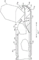
Fig. 1 is a perspective view of a surgical instrument according to an exemplary embodiment of the present disclosure.
FIG. 2 is an exploded perspective view of the surgical instrument of FIG. 1 with the drive assembly removed.
Fig. 3 is a perspective view of a blockage-reducing tip of a cutting assembly of the surgical instrument of fig. 1 and 2, according to an exemplary embodiment of the present disclosure.
Fig. 4 is a partial front view of the occlusion reducing tip of the cutting assembly of fig. 3 schematically illustrating material being removed.
Fig. 5 is another partial front view of the occlusion reduction tip of the cutting assembly of fig. 3.
Fig. 6 is yet another partial front view of the occlusion reducing tip of the cutting assembly of fig. 3.
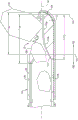
Fig. 7 is a cross-sectional view of the cutting assembly of fig. 3 taken along line 7-7.
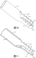
Fig. 8 is a perspective view of an occlusion reduction tip according to another exemplary embodiment of the present disclosure.
Fig. 9 is a partial perspective view of the occlusion reduction tip of fig. 8.
Fig. 10 is a perspective view of an occlusion reduction tip according to yet another exemplary embodiment of the present disclosure.
Fig. 11 is a partial perspective view of the occlusion reduction tip of fig. 10.
Fig. 12 is a perspective view of an occlusion reduction tip according to yet another exemplary embodiment of the present disclosure.
Fig. 13 is a front view of the occlusion reduction tip of fig. 12.
Fig. 14 is an angled view of the occlusion reducing tip of fig. 12.
Fig. 15 is a plan view of the occlusion reduction tip of fig. 12.
Fig. 16-19 are schematic diagrams illustrating a machining process for forming the blockage-reducing tip of fig. 12-15.
FIG. 20 is a cross-sectional view of the surgical instrument of FIG. 1 taken along line 20-20.
Detailed Description
Referring to fig. 1, one embodiment of a surgical instrument 10 according to the present disclosure is shown for use in a medical procedure of a patient (not shown). In one embodiment, surgical instrument 10 is disposable and is an ENT resector for resecting sinus bone and tissue during endoscopic sinus surgery. As shown, the surgical instrument 10 includes a drive assembly, generally indicated at 12 and shown in phantom, and a cutting assembly, generally indicated at 14, removably coupled to the drive assembly 12. The drive assembly 12 is used to rotate a portion of the cutting assembly 14 to remove tissue, bone, etc. from a surgical site of a patient. It should be understood that the surgical instrument 10 may be operated by a user (not shown), such as a surgeon.
As shown in fig. 1, the drive assembly 12 includes an axially extending housing 15. The housing 15 is substantially cylindrical. The drive assembly 12 also includes a motor 16 disposed in the housing 15 and having a rotatable drive element 18 coupled to the cutting assembly 14. The motor 16 may be of the electric or pneumatic type. In one embodiment, the drive element 18 is removably coupled to the cutting assembly 14.
It should be appreciated that in one embodiment, the cutting assembly 14 may be devoid of any motor. Accordingly, the cutting assembly 14 may be configured to be disposable after a single use or a series of uses. Because the cutting assembly 14 may not include any motors, the cost of the cutting assembly 14 may be reduced.
Referring to fig. 1-7, the cutting assembly 14 comprises a plurality of tubes or tube assemblies, generally indicated at 20, extending axially between a distal end 23 and a proximal end 21 (fig. 20) opposite the distal end 23. The tube assembly 20 has a longitudinal axis 24 defined between the proximal end 21 and the distal end 23. Tube assembly 20 includes a window 22, such as a cutting window, near or at distal end 23, where window 22 is adapted to be applied to a surgical site of a patient. In certain embodiments, tube assembly 20 includes a first or outer tube 26 and a second or inner tube 28. Inner tube 28 is coupled to drive assembly 102 and is rotatable relative to outer tube 26 by drive element 18. Inner tube 28 may be removably coupled to drive element 18 (e.g., in embodiments where cutting assembly 14 may be disposed of after a single use or a series of uses).
In one embodiment, the outer tube 26 is non-rotatable and the inner tube 28 is rotatable relative to the outer tube 26. Inner tube 28 has a lumen 30 extending between proximal end 21 and distal end 23 of tube assembly 20. Inner tube 28 may include a proximal region 32 and a distal region 34 as will be described. The inner tube 28 includes, forms, or defines a first or inner cutting window 36 at or near the distal end 23 of the tube assembly 20, such as within the distal region 34 of the inner tube 28.
Each of the inner tube 28 and the outer tube 26 may be a generally hollow, axially extending cylinder and have a generally circular cross-sectional shape. The diameter of the outer tube 26 is larger than the diameter of the inner tube 28 so that the inner tube 28 is disposed within the outer tube 26. In other words, the outer tube 26 has a lumen extending between the proximal end 21 and the distal end 23 of the tube assembly 20, with the inner tube 28 at least partially disposed within the lumen of the outer tube 26. In one embodiment to be described (see fig. 20), the axial length of the inner tube 28 is greater than the axial length of the outer tube 26 such that when the inner tube 28 is disposed within the outer tube 26, the inner tube 28 extends beyond the proximal end region 38 of the outer tube 26.
As shown in fig. 2, the outer tube 26 may include a proximal region 38 and a distal region 40. The outer tube 26 forms a second or outer cutting window 42 at or near the distal end 23 of the tube assembly, such as in the distal region 40 of the outer tube 26. The inner and outer cutting windows 36, 42 define the cutting window 22 of the tube assembly 20. In an exemplary embodiment, the outer tube 26 may include a radially reduced step 44 in the distal region 34 to allow the outer surface of the inner tube 28 and the inner surface of the outer tube 26 to abut together.
In one embodiment, tube assembly 20 may further include a non-rotatable sheath or third or cover tube 46 disposed over a portion of outer tube 26. The axial length of the cover tube 46 is less than the axial length of the outer tube 26. The cover tube 46 may be angled, straight, or malleable. It should be understood that the cover tube 46 is optional. Additionally, it should be understood that the cover tube 46 is coupled to a connection hub 68 as will be described. Further, it should be understood that any suitable tube configuration may be used as long as the cutting assembly 14 defines the cutting window 22 and is capable of being driven by the drive assembly 12.
Depending on the application, inner tube 28 and outer tube 26 are made of a metallic material, such as stainless steel, or a non-metallic material, such as a composite material. Depending on the application, the cover tube 46 may be made of a metallic material or a non-metallic material such as a composite material. It should be appreciated that the wall thickness of inner tube 28 and outer tube 26 is relatively thin, such as about 0.1 to about 0.5 millimeters (mm), to allow tube assembly 20 to have a relatively small diameter and also be lightweight. It should also be appreciated that the diameters of the inner tube 28 and the outer tube 26 have relatively small diameters, such as about 2.0mm to about 5.0mm, to operate in small openings of the nasal or oral cavity of a patient and prevent obstruction of the user's view. In one embodiment, tube assembly 20 may have a bend (not shown) near distal end 23. It should also be understood that inner tube 28 and outer tube 26 may be scaled larger or smaller depending on the application.
Cutting assembly 14 also includes a drive hub, generally indicated at 48, disposed about the proximal end of inner tube 28 to allow inner tube 28 to be connected to drive element 18 to facilitate rotation of inner tube 28 about longitudinal axis 24. The drive hub 48 includes a hub member 50 disposed about the inner tube 28. The hub member 50 extends axially and is generally cylindrical. As shown in fig. 2, the hub member 50 has an axially extending bore 52 at least partially therethrough to receive the inner tube 28. The hub member 50 may also include a plurality of ridges 54 extending radially and axially and spaced circumferentially thereabout. The hub member 50 may also include a reduced diameter portion 56 adjacent the ridge 54. The reduced diameter portion 56 of the hub member 50 defines a reduced bore 53 in communication with the bore 52, wherein the diameter of the reduced bore 53 is less than the diameter of the bore 52 (see fig. 20). The reduction in diameter from bore 52 to reduced bore 53 forms a lip 55, lip 55 being adapted to be positioned adjacent to proximal end 21 of tube assembly 20 or in abutting relationship with proximal end 21 of tube assembly 20 in a manner to be described. The hub member 50 also includes a radially extending flange 58 at its distal end. The hub member 50 may be made of a non-metallic material. The hub member 50 may be complete, unitary and integrally formed.
The drive hub 48 may also contain a spring 60 and a seal 62, such as an O-ring, disposed in the reduced diameter portion 56 around the hub member 50 at its proximal end. The drive hub 48 may include a washer 64 and a seal 66, such as an O-ring, disposed about the distal end of the inner tube 28 at the distal end thereof. It should be appreciated that the drive hub 48 allows for rotation of the inner tube 28 and may allow for the transfer of fluid through the inner tube 28. It should also be understood that the cutting assembly 14 may be used with a variety of drive coupling configurations.
Cutting assembly 14 also includes a coupling hub, generally indicated at 68, disposed about a portion of inner tube 28 and drive hub 50 to allow drive assembly 12 to be removably coupled to cutting assembly 14. The coupling boss 68 includes a housing boss 70 adapted to be engaged by at least a portion of a user's hand and to support the outer tube 26 or the cover tube 46. The housing hub 70 includes a bore 72 extending axially therethrough to receive the outer tube 26 or the cover tube 46. The housing hub 70 may include a plurality of gripping members 74 extending radially and axially and a flange 76 extending radially outward at one end to support one or more fingers of a hand. The connection hub 68 also includes a coupling member 78 disposed about the inner tube 28. The coupling member 78 extends axially and is generally cylindrical. Coupling member 70 has a bore 72 extending axially therethrough to receive inner tube 28. The coupling member 78 includes a cavity 80 extending axially into a proximal end thereof to receive a distal end of the fluid coupling 72. The coupling member 78 may include one or more ridges 82 extending radially at the proximal end and spaced circumferentially from one another to couple to the housing 15 of the drive assembly 12. The coupling member 78 may include one or more grooves 84 extending radially inward and circumferentially and axially spaced from one another, and one or more seals 86, such as O-rings, disposed in the grooves 84. The coupling boss 68 is made of a non-metallic material. The connecting boss 68 may be integral, unitary and one-piece. It should be appreciated that the connection hub 68 allows the drive assembly 12 to be coupled to the cutting assembly 14.
Referring to fig. 3, cutting window 22 comprises an inner cutting window 36 formed in inner tube 28 as an opening extending axially and diametrically through the wall on one side near distal end 23 of tube assembly 20. The cutting window 22 also includes an outer cutting window 42 formed in the outer tube 26 as an opening extending axially and diametrically through the wall on one side near the distal end 23 of the tube assembly 20. The inner and outer cutting windows 36 and 42 are generally elongated oval in shape, but may be any suitable shape. The inner cutting window 36 may include at least one or more cutting edges 90. The cutting edge 90 may include a plurality of teeth 92 that form a serrated edge. The outer cutting window 42 may include at least one or more cutting edges 94. The cutting edge 94 may include a plurality of teeth 92 that form a serrated edge. The inner cutting window 36 is adapted to be temporarily (temporarily) radially aligned with the outer cutting window 42 to receive material within the cutting window 22 as the inner tube 28 is rotated within the outer tube 26. As the inner and outer cutting windows 36 and 42 are rotated within the outer tube 26, the inner and outer cutting windows 36 and 42 are disengaged from radial alignment such that the cutting edges 90 and 94 cut or reduce the material positioned within the cutting window 22 of the tube assembly 20.
In one embodiment shown in fig. 1, surgical instrument 10 includes a flush connection 95 on housing 15 for connection to a fluid source, and a flush path or passage 96 extending through housing 15 to window 22 between flush connection 95 and cutting assembly 14 and between inner tube 28 and outer tube 26 to provide lubrication. Surgical instrument 10 also includes a suction or aspiration connection 97 on housing 15 for connection to a suction source, and a suction or aspiration path or passage 98 extending through housing 15 between suction connection 97 and first cutting window 36 of inner tube 28.
Fig. 4-6 illustrate partial front views of an occlusion reducing tip, generally indicated at 104, according to an exemplary embodiment of the present disclosure. Referring first to fig. 4, cutting window 22 of tube assembly 20 includes a distal boundary 103 and a proximal boundary 101 opposite distal boundary 103. In one embodiment, boundaries 101 and 103 may be defined as imaginary planes extending perpendicular to longitudinal axis 24 of tube assembly 20 at the proximal-most point and distal-most point of cutting window 22, respectively. Thus, in the exemplary embodiment shown in fig. 4, the outer tube 26 protrudes at the distal end of the inner tube 28 to define the proximal boundary 101 of the cutting window 22, and at the distal end 23, the inner tube 28 is positioned at the proximal end of the outer tube 26 (i.e., within) to define the distal boundary 103 of the cutting window 22. In other words, when the cutting window 22 is viewed in plan, the proximal and distal boundaries 101 and 103 may be considered as the most proximal and most distal points, respectively, of the cutting window 22. In certain embodiments, the portion of the inner tubing 28 distal of the proximal boundary 101 of the cutting window 22 defines the distal region 34 of the inner tubing 28.
As shown in fig. 4, occlusion-reducing tip 104 of tube assembly 20 includes a protrusion 112 within lumen 30 of inner tube 28. The projections 112 are adapted to reduce the size of material that may be removed through the cutting window 22, thereby reducing clogging of the tube assembly 20. In certain embodiments, at least a portion of protrusion 112 is positioned distal (in the direction of arrow 102 in fig. 4) to proximal boundary 101 to provide a reduced cross-sectional area to lumen 30 relative to the cross-sectional area of lumen 30 proximal of protrusion 112. In another example, the protrusion 112 occupies a volume V within the distal region 34 of the inner tube 28112(FIG. 5). The projections 112 reduce the amount of material 106 to be removed that can penetrate the cutting window 22. Thus, the cutting action created by rotating inner tube 28 within outer tube 26 (via cutting edges 90 and 94) reduces material 106 into pieces small enough before material 106 can pass within lumen 30 proximal of cutting window 22, thereby reducing the likelihood of tube assembly 20 becoming clogged.
In certain embodiments, the reduced cross-sectional area of lumen 30 may be defined as the difference between the cross-sectional area of lumen 30 (e.g., pi x d, where d is the diameter of lumen 30) and the cross-sectional area of protrusion 112. In one example, the ratio of the reduced cross-sectional area of the lumen 30 to the cross-sectional area of the lumen 30 is in the range of 1: 1.1 to 1: 2.0, and more specifically in the range of 1: 1.3 to 1: 1.8, even more particularly in the range of 1: 1.5 to 1: 1.6. The reduced cross-section is adapted to ensure that the size of the material 106 (e.g., bone and/or tissue fragments) is no greater than the cross-sectional area of the lumen 30, and more particularly is less than the cross-sectional area of the lumen 30 by a predetermined factor based on the above-described ratio. In other exemplary embodiments, the volume V (occupied) of the protrusion 112 disposed within the distal region 34112Volume V at distal region 34 of tube assembly 2020In the range of 10% -70%, and more particularlyVolume V at (occupying) distal region 3420In the range of 20% -60% (see fig. 5).
In one exemplary operation of a conventional ENT exciser, material can be passed through the cutting window to contact the inner tube opposite the cutting window, such that the reduced material size is approximately equal to the diameter of the lumen. The reduced material having a dimension approximately equal to the diameter of the lumen increases the likelihood of the reduced material clogging within the lumen, particularly near the cutting window. In addition, the reduced likelihood of material blockage in conventional ENT resectors is further increased where the axial length of the cutting window is greater than the diameter of the lumen.
The occlusion-reducing tip 104 of the present disclosure significantly reduces the likelihood of occlusion by, for example, setting the distance from the proximal boundary 101 of the cutting window 22 at the outer tube 26 to the closest point on the projection 112 (approximately point 105 shown in fig. 4) to be less than the diameter of the lumen 30. Thus, any reduction in the size of the material 106 that may pass through the "throat" (i.e., the distance from the cutting window 22 to the closest point 105) is less than the diameter of the lumen 30 itself. Thus, once the reduced material reaches the lumen 30 proximal of the projection 112, the reduced material is less likely to occlude the tube assembly 20.
Before the material is sufficiently reduced to pass through the "throat" of inner tube 26, tabs 112 (and proximal boundary 101 of cutting window 22) hold material 106 in place so that the cutting action continues to reduce material 106 with each rotation of inner tube 28. Although material 106 may remain positioned adjacent cutting window 22 for a longer period of time, empirical studies have shown minimal impact on the material removal capability of tube assembly 20 including occlusion reducing tip 104, nearly or completely eliminating the occlusion typically associated with conventional ENT resectors.
With continued reference to fig. 4 and simultaneous reference to fig. 6, the protrusion 112 may extend within the lumen 30 from near the distal end 23 of the tube assembly 20 to a location proximal of the proximal boundary 101 (i.e., in the direction of arrow 100). In other words, the further portion 113 of the protrusion 112 may be located proximal to the proximal boundary 101. In other words, the axial length L of the projection 112112May be greater than the axial length of the cutting window 22L22. Positioning portion 113 of tab 112 proximal of proximal boundary 101 ensures that material 106 passing through proximal boundary 101 is reduced to a size less than the cross-sectional area of lumen 30 of tube assembly 20. It should be understood that the axial length L of the projection 112112May be greater than the axial length L of the outer cutting window 4242And/or less than the axial length L of the inner cutting window 3636. In some embodiments, the protrusion 112 may extend even more proximally of the proximal boundary 101 than shown in fig. 4 and 6 with the proximal second portion 110b having a shallower taper to be described.
The projection 112 of the jam-reducing tip 104 has a shelf or inner surface 110. Inner surface 110 is displaced radially inward toward longitudinal axis 24 of tube assembly 20 relative to inner surface 108 of lumen 30 (i.e., proximal of protrusion 112). Referring to fig. 5, the protrusion 112 may be angled relative to the interior surface 108 of the lumen 30. For example, a line extending between the distal and proximal ends of the protrusion 112 may be oriented at an angle a in the range of about 5 degrees to about 40 degrees relative to the interior surface 108 of the lumen 30. In other embodiments, the angle α is between about 10 degrees and about 30 degrees, and more specifically between about 15 degrees and about 25 degrees. This angle a generally provides the projection 112 with a narrowing profile in the direction of arrow 100 (when viewed in elevation as shown in fig. 4-6). In other words, the distance from the longitudinal axis 24 to the protrusion 112 at the distal boundary 103 of the cutting window 22 is smaller than the distance from the longitudinal axis 24 to the protrusion 112 at the proximal boundary 101 of the cutting window 22, such that the protrusion 112 is gradually narrowing in a direction towards the proximal boundary 101. The tapering of the tab 112 advantageously keeps the material 106 near the distal boundary 103 closer to the cutting edges 90 and 94 to reduce the material 106 into smaller pieces as the reduced material 106 moves along the inner surface 110 of the tab 112 toward the lumen 30 proximal of the cutting window 22. The gradual narrowing of the protrusion 112 also ensures a gradual transition through the "throat" as previously described, such that the reduced material 106 passing through the "throat" immediately encounters the larger cross-sectional area of the lumen 30 and is rapidly pushed proximally within the lumen 30 under force from the suction source.
In some embodiments, the inner surface 110 of the tab 112 further includes or is defined by a distal first portion 110a and a proximal second portion 110b proximal to the distal first portion 110 a. Refer to fig. 5 and 6. The distal first portion 110a may be oriented substantially parallel to the longitudinal axis 24 of the tube assembly 20. The distal first portion 110a may be substantially planar when viewed in elevation. The proximal second portion 110b may be inclined or angled relative to the distal first portion 110a and the interior surface 108 of the lumen 30. The proximal second portion 110b may be arcuate (curved) when viewed in elevation to provide a smooth transition to the distal first portion 110 a. The proximal second portion 110b may be oriented at an angle β in a range of about 20 degrees to about 60 degrees relative to the interior surface 108 of the lumen 30. In other embodiments, the angle β is between about 30 degrees and about 50 degrees.
Referring to fig. 7, the tab 112 may be positioned about the longitudinal axis 24 radially opposite the cutting window 22 of the tube assembly 20 (more specifically, radially opposite the inner cutting window 36). With the protrusion 112 located within the lumen 30 of the inner tube 28, the relative positioning between the protrusion 112 and the inner cutting window 36 remains unchanged as the inner tube 28 is rotated within the outer tube 26. The radial position of the cutting window 22 of fig. 7 is approximately between lines W1 and W2, with the tab 112 positioned about the longitudinal axis 24 substantially opposite the space between lines W1 and W2.
In certain embodiments, occlusion reducing tip 104 includes an insert secured within lumen 30 of inner tube 28. The insert defines a protrusion 112 and forms an inner surface 110. For example, the insert may be bonded to the lumen 30 of the inner tube 28. The insert may comprise an outer surface 111 and an inner surface 110, wherein the outer surface 111 is shaped to conform to a portion of the lumen 30 (see fig. 7). The inner surface 110 may define a protrusion 112. The insert may have a thickness defined between the inner surface 110 and the outer surface 111, wherein the thickness of the insert tapers in the axial direction, i.e. in the direction 100 towards the proximal boundary 101 of the cutting window 22. It should also be appreciated that the thickness of the insert may taper (narrow) radially about the longitudinal axis 24 of the tube assembly 20, as shown in fig. 7.
In yet another exemplary embodiment of the occlusion reducing tip 104 shown in fig. 10 and 11, the protrusion 112 is defined by the lumen 30 distal of the proximal boundary 101, formed radially inward toward the longitudinal axis 24. In other words, the tabs 112 of fig. 4-6 are located within the lumen 30 with the inner tube 28 having a generally cylindrical outer profile to the distal end 23 of the tube assembly 20, while fig. 10 and 11 show the inner tube 28 (e.g., the distal region 34) near the distal end 23 deformed inwardly toward the longitudinal axis 24. As a portion of inner tube 28 deforms inwardly, lumen 30 of inner tube 28 correspondingly deforms inwardly and thus defines tabs 112 that provide the reduced cross-sectional area of lumen 30 as previously described. The inwardly deformed portion of inner tube 28 may be constructed by stamping, drawing (drawing), or similar suitable manufacturing process.
Referring to fig. 12-15, a blockage-reducing tip 104 is shown according to yet another embodiment of the present disclosure. In this embodiment, the occlusion reducing tip 104 includes an inner surface 110 formed by drilling an eccentric bore in the distal region 34 of the inner tube 28. The bore is eccentric relative to the longitudinal axis 24 of the tube assembly 24. The eccentric bore communicates with the cutting window 22 and the lumen 30 of the inner tube 28. Tips of this type are typically machined. As shown, the inner surface 110 has a smaller cross-section at the first cutting window 36. The process of machining the jam-reducing tip 104 is shown in fig. 16-19.
The present disclosure provides a method for operating a surgical instrument 10 on a patient according to one embodiment of the present disclosure. The method includes the step of providing a cutting assembly 14 comprising an axially extending tube assembly 20. Tube assembly 20 includes a rotatable inner tube 28 having a lumen 30 coaxially disposed within outer tube 26. The inner tube 28 forms an inner cutting window 36 and the outer tube 28 forms an outer cutting window 42. The inner and outer cutting windows 36, 42 define the cutting window 22 of the tube assembly 20. The method may further comprise the step of providing a protrusion 112 within the lumen 30 of the inner tube 28, wherein at least a portion of the protrusion 112 is disposed within the distal region 34 of the inner tube 28 with the protrusion 112. In certain embodiments, the protrusion 112 is positioned distal to the proximal boundary 101 of the cutting window 22. The projection 112 provides the inner tube 28 with a reduced cross-sectional area relative to the cross-sectional area of the lumen proximal of the projection 112. In certain embodiments, the protrusion 112 is (has) a volume V of the lumen 30 occupying the distal end of the proximal boundary 101 of the cutting window 2220Volume V of112. The method includes the steps of applying a cutting window to a surgical site of a patient and rotating inner tube 28 relative to outer tube 26 via drive assembly 12 to cut material 106 via the interaction of inner cutting window 36 and outer cutting window 42, wherein tabs 112 reduce the size of material 106 removed through cutting window 22 to reduce clogging of tube assembly 20.
The surgical instrument 10 of the present disclosure also advantageously reduces the likelihood of blockage at the tube assembly 20 of the surgical instrument 10 or just proximal of the tube assembly 20 of the surgical instrument 10. Fig. 20 is a cross-sectional view of a portion of the surgical instrument of fig. 1, particularly illustrating an interface 114 between tube assembly 20 and drive hub 48. As previously mentioned, the hub member 50 of the drive hub 48 includes a reduced diameter portion 56 defining a reduced bore 53 in communication with the bore 52 of the drive hub 48 (and the connecting hub 68). Lip 55 is formed by a reduction in diameter from aperture 52 to reduced aperture 53. As shown in fig. 20, the axial length of the inner tube 28 is greater than the axial length of the outer tube 26 such that the inner tube 28 extends beyond the proximal end region 38 of the outer tube 26 and into the connecting hub 68 and the drive hub 48.
During assembly of surgical instrument 10, such as when coupling tube assembly 20 with drive hub 48, inner tube 28 is slidably inserted within bore 52 of drive hub 48 and positioned adjacent lip 55 or in abutting relationship with lip 55. Lip 55 facilitates proper axial positioning of tube assembly 20 relative to housing 15 and other structures of surgical instrument 10. As shown in FIG. 20, lumen 30 of inner tube 28 is in fluid communication with reduced bore 53 of drive hub 48 such that reduced material 106 may pass from lumen 30 to the suction source.
The diameter of the lumen 30 of the inner tube 28 is smaller than the diameter of the reduced bore 53 at the interface 114. In other words, as the material 106 passes through the interface 114, the reduced material 106 moves from the smaller cross-sectional area of the lumen 30 to the larger cross-sectional area of the reduced aperture 53. In effect, the passage through which the reduced material moves is enlarged, thereby reducing the likelihood of blockage. As a comparative example, if the diameter of the lumen 30 of the inner tube 28 is greater than the diameter of the reduced orifice 53, the reduced material 106 may catch on the lip 55 and increase the likelihood of blockage at the interface 114.
Thus, according to an exemplary embodiment of the present disclosure, a cutting assembly for a surgical instrument having a drive assembly, the cutting assembly comprising: a tube assembly including a cutting window near a distal end and adapted for application to a surgical site of a patient, an outer tube, an inner tube coaxially disposed within the outer tube and rotatable relative to the outer tube by the drive assembly, wherein the inner tube includes a lumen; and a drive hub coupled to the inner tube, wherein the drive hub defines a bore adapted to slidably receive a proximal end of the inner tube and defines a reduced bore in communication with the bore, wherein a diameter of the reduced bore is less than a diameter of the bore, wherein a diameter of the lumen is less than the diameter of the reduced bore when the proximal end of the inner tube is slidably received within the bore to reduce occlusion of the surgical instrument when removed material moves from the lumen to the reduced bore of the drive hub. A lip is formed at an interface between the bore and the reduced bore, wherein the proximal end of the inner tube is adapted to be positioned adjacent the lip.
Accordingly, the surgical instrument 10 of the present disclosure reduces the occurrence of obstruction by providing an obstruction reducing tip 104 having a protrusion 112 that serves to reduce the cross-sectional area of the lumen 30 distal of the proximal boundary 101 of the cutting window 22 and/or serves to reduce the volume V at the distal region 34 of the tube assembly 2020Internal supply volume V112. The size of the material 106 that can enter the distal end region 34 of the inner tubing 28 is limited and held in place to be further reduced by the cutting action. In addition, only material 106 that is reduced in size sufficiently may pass through the "throat" of tube assembly 20, after which reduced material 106 also encounters the larger cross-section of lumen 30 under suction. The protrusion 112 may be an insert secured with the lumen 30 of the inner tube 28 or integrally formed with the inner tube 28, such as by deforming the distal region 34 of the inner tube 28, providing a bore eccentric to the longitudinal axis 24 of the tube assembly 24, or appropriately milling within the inner tube 28 to define the protrusion 112. The surgical instrument 10 of the present disclosure cuts and aspirates tissue according to current resector systems that utilize suction. It should be understood that in another embodiment, the surgical instrument 10 may be used with a surgical tool or be a dedicated tool or instrument.
It will be further understood that the terms "comprises," comprising, "and" including "have the same meaning as the terms" comprising, "" comprises, "and" comprising.
The invention has been described in an illustrative manner. It is to be understood that the terminology, which has been used, is intended to be in the nature of words of description rather than of limitation. Many modifications and variations of the present invention are possible in light of the above teachings. Thus, the invention may be practiced otherwise than as specifically described.
Embodiments of the present disclosure may be described with reference to the following exemplary clauses:
clause 1-a cutting assembly of a surgical instrument for cutting tissue, the cutting assembly configured to be coupled to a drive assembly, the drive assembly including a motor having a rotatable drive element enclosed in a housing, and the cutting assembly comprising: a rotatable first tube having a lumen with a proximal region and a distal region, the first tube forming a first cutting window in the distal region; a second tube disposed over the first tube, the second tube having a proximal region and a distal region, the second tube forming a second cutting window in the distal region; the first tube is rotatable relative to the second tube; the cross-sectional area of the proximal region of the window of the lumen is greater than the cross-sectional area of the distal region of the lumen such that tissue cut by the interaction of the first and second cutting windows is sized to allow passage through the first and distal regions of the lumen to the proximal region of the lumen to prevent occlusion of the distal region of the lumen.
Clause 2-the cutting assembly of clause 1, wherein the proximal region of the lumen has an interior surface and the distal region of the lumen has an interior surface opposite the first cutting window.
Clause 3-the cutting assembly of clause 2, wherein the inner surface is displaced radially inward relative to the inner surface.
Clause 4-the cutting assembly of clause 2, wherein the inner surface extends radially and axially at an angle greater than zero relative to the inner surface.
Clause 5-the cutting assembly of clause 2, which includes an insert disposed within the distal region of the lumen opposite the first cutting window and forming the inner surface.
Clause 6-the cutting assembly of clause 5, wherein the insert is bonded to the first tube.
Clause 7-the cutting assembly of clause 5, wherein the insert includes the inner surface extending radially and axially at an angle greater than zero relative to the inner surface.
Clause 8-the cutting assembly of clause 5, wherein the insert has one of a generally arcuate, semi-circular, and rectangular cross-sectional profile.
Clause 9-the cutting assembly of clause 5, wherein the insert is made from one or more different materials.
Clause 10-the cutting assembly of clause 2, wherein the inner surface is defined by the inner tube in the distal region of the lumen opposite the first cutting window.
Clause 11-the cutting assembly of clause 2, wherein the inner surface extends axially from a distal end of the distal region of the lumen to less than one of a proximal end of the first cutting window and a proximal end of at least the first cutting window.
Clause 12-the cutting assembly of clause 11, wherein the axial length of the first cutting window is less than the axial length of one of the inner surface and the second cutting window.
Clause 13-the cutting assembly of clause 11, wherein the angle of the inner surface relative to the wall of the distal region of the lumen is between about 20 degrees and about 90 degrees.
Clause 14-the cutting assembly of clause 11, wherein the radial height of the inner surface is greater than the radial height of the inner surface.
Clause 15-the cutting assembly of clause 1, which comprises a third tube disposed over the second tube.
Clause 16-the cutting assembly of clause 1, wherein the distal region of the lumen has a profile formed by one of a drawing process and a machining process.
Clause 17-the cutting assembly of clause 16, wherein the distal region of the lumen has a non-circular cross-section.
Clause 18-the cutting assembly of clause 1, wherein the first cutting window comprises at least one cutting edge.
Clause 19-the cutting assembly of clause 1, which includes a suction path connected to either of the first tube and the second tube.
Clause 20-the cutting assembly of clause 1, wherein the cross-section of the distal region of the lumen and (and) the cross-section of the proximal region of the lumen have a cross-sectional area of 1: 1.5, 1: 3 and 1: 6, in the first step.
Clause 21-the cutting assembly of clause 1, wherein an axial length of the first cutting window relative to a diameter of the distal region of the lumen is such that a size of a cut bone fragment is not greater than a diameter of the lumen in the proximal region.
Clause 22-a surgical instrument for use with a patient, the surgical instrument comprising: a cutting assembly comprising a plurality of axially extending tubes including at least one rotatable inner tube having a lumen with a proximal region and a distal region, the inner tube forming an inner cutting window in the distal region, an outer tube disposed over the inner tube, the outer tube having a proximal region and a distal region, the outer tube forming an outer cutting window in the distal region, the inner tube rotatable relative to the outer tube; a drive assembly including a motor having a rotatable drive element, a housing for enclosing the motor and removably coupled to the cutting assembly, a suction connection on the housing for connection to a suction source, and a suction channel extending from the inner window through the inner tube and through the housing to the suction connection; a flush connection on the housing for connection to a fluid source; an irrigation channel extending through the housing between the irrigation coupling and the cutting assembly and between the inner tube and the outer tube to the cutting window to provide lubrication and irrigation of blood, tissue, and bone; a suction connection on the housing for connection to a suction source; a suction channel extending through the housing between the suction connection and the cutting window of the inner tube; and the proximal region of the lumen has a cross-sectional area greater than a cross-sectional area of the distal region of the lumen such that tissue cut by the interaction of the inner and outer cutting windows is of a suitable size to allow passage through the inner and distal regions of the lumen to the proximal region of the lumen to prevent occlusion of the distal region of the lumen.
Clause 23-a method of operating a surgical instrument for a patient, the method comprising the steps of: providing a cutting assembly comprising a plurality of axially extending tubes, the tubes including an inner tube having at least one rotatable lumen with a lumen having a proximal end region and a distal end region, the inner tube forming an inner cutting window in the distal end region, an outer tube disposed on the inner tube, the outer tube having a proximal end region and a distal end region, the outer tube forming an outer cutting window in the distal end region, the inner tube being rotatable relative to the outer tube; providing a drive assembly including a motor having a rotatable drive element, a housing for enclosing the motor and removably coupled to the cutting assembly, a suction connection on the housing for connection to a suction source, and a suction channel extending from the inner window through the inner tube and through the housing to the suction connection; providing a proximal region of the lumen having a cross-sectional area greater than a cross-sectional area of the distal region of the lumen; rotating the inner tube relative to the outer tube by the drive assembly; cutting bone and/or tissue in a patient through interaction of the inner cutting window and the outer cutting window; and allowing cut bone and/or tissue of a suitable size to pass through the inner cutting window and the distal region of the lumen to the proximal region of the lumen to prevent occlusion of the distal region of the lumen.
Clause 24-surgical instruments, cutting assemblies, and methods as disclosed and described herein, which include equivalents not specifically recited herein.
Claims (15)
1. A cutting assembly for a surgical instrument having a drive assembly, the cutting assembly comprising:
a tube assembly including a longitudinal axis extending proximally from a distal end opposite a proximal end and a cutting window proximate the distal end and adapted for application to a surgical site of a patient, wherein the cutting window includes a proximal boundary and a distal boundary opposite the proximal boundary, the tube assembly further comprising:
an outer tube comprising an outer cutting window near the distal end of the tube assembly;
an inner tube coaxially disposed within the outer tube and rotatable relative to the outer tube by the drive assembly, the inner tube including an inner cutting window near the distal end and a lumen extending between the proximal end and the inner cutting window, wherein the inner cutting window and the outer cutting window define the cutting window of the tube assembly; and
a protrusion located within the lumen of the inner tube, wherein at least a portion of the protrusion is positioned distal to the proximal boundary of the cutting window, the protrusion providing the lumen of the inner tube with a reduced cross-sectional area relative to a cross-sectional area of the lumen proximal of the protrusion, wherein the reduced cross-sectional area is adapted to reduce a size of material that is removable through the cutting window to reduce clogging of the tube assembly.
2. The cutting assembly of claim 1, further comprising an insert secured within the lumen of the inner tube, wherein the insert defines the protrusion providing the reduced cross-sectional area.
3. The cutting assembly of claim 2, wherein the insert includes an outer surface and an inner surface opposite the outer surface, wherein the outer surface is shaped to conform to a portion of the lumen and the inner surface defines the protrusion.
4. The cutting assembly of claim 3, wherein a thickness of the insert defined between the inner surface and the outer surface tapers in a direction toward the proximal boundary of the cutting window.
5. The cutting assembly of claim 1, wherein the lumen of the inner tube distal of the proximal boundary of the cutting window is formed radially inward toward the longitudinal axis to define the protrusion providing the reduced cross-sectional area.
6. The cutting assembly of claim 1, wherein a ratio of the reduced cross-sectional area of the inner tube to the cross-sectional area of the lumen is between 1: 1.3 to 1: 1.8.
7. A cutting assembly for a surgical instrument having a drive assembly, the cutting assembly comprising:
a tube assembly including a longitudinal axis extending proximally from a distal end opposite a proximal end and a cutting window proximate the distal end and adapted for application to a surgical site of a patient, the cutting window including a proximal boundary and a distal boundary opposite the proximal boundary, the tube assembly further comprising:
an outer tube including an external cutting window within the distal end region;
an inner tube coaxially disposed within the outer tube and rotatable relative to the outer tube by the drive assembly, wherein a portion of the inner tube distal of the proximal boundary of the tube assembly defines a distal region of the inner tube, the inner tube including an inner cutting window within the distal region, wherein the inner and outer cutting windows define the cutting window of the tube assembly; and
a protrusion within the inner tube, wherein at least a portion of the protrusion is disposed within the distal end region of the inner tube, wherein the protrusion is adapted to reduce the size of material removed through the cutting window to reduce clogging of the tube assembly.
8. The cutting assembly of claim 7, wherein a volume of the protrusion disposed within the distal region is in a range of 20% to 60% of a volume of the distal region of the tube assembly.
9. The cutting assembly of claim 1 or 7, wherein another portion of the protrusion is positioned proximal to the proximal boundary of the cutting window.
10. The cutting assembly of claim 1 or 7, wherein the protrusion is positioned about the longitudinal axis radially opposite the inner cutting window.
11. The cutting assembly of claim 1 or 7, wherein a distance from the longitudinal axis to the protrusion at the distal boundary of the cutting window is less than a distance from the longitudinal axis to the protrusion at the proximal boundary of the cutting window such that the protrusion tapers in a direction toward the proximal boundary.
12. The cutting assembly of claim 1 or 7, wherein the protrusion is further defined by a distal first portion including a substantially planar inner surface and a proximal second portion proximal to the distal first portion, wherein the proximal second portion includes an arcuate inner surface.
13. The cutting assembly of claim 1 or 7, wherein a distance from the proximal boundary of the cutting window at the outer tube to a closest point on the protrusion is smaller than a diameter of a lumen of the inner tube such that a size of the reduced material delivered to the lumen is at most equal to the distance smaller than the diameter of the lumen, thereby reducing clogging of the tube assembly.
14. The cutting assembly of claim 1 or 7, wherein the protrusion is defined at least in part by an eccentric bore located within the distal end region of the inner tube and eccentric to the longitudinal axis, wherein the eccentric bore is in communication with the cutting window and a lumen of the inner tube.
15. The cutting assembly of claim 1 or 7, wherein the relative positioning between the protrusion and the inner cutting window remains unchanged as the inner tube is rotated within the outer tube.
Priority Applications (1)
| Application Number | Priority Date | Filing Date | Title |
|---|---|---|---|
| CN202111633402.1A CN114271899A (en) | 2016-07-14 | 2017-07-14 | Cutting assembly for surgical instrument having occlusion-reducing tip |
Applications Claiming Priority (3)
| Application Number | Priority Date | Filing Date | Title |
|---|---|---|---|
| US201662362117P | 2016-07-14 | 2016-07-14 | |
| US62/362,117 | 2016-07-14 | ||
| PCT/US2017/042101 WO2018013906A1 (en) | 2016-07-14 | 2017-07-14 | Cutting assembly for surgical instrument with clog reducing tip |
Related Child Applications (1)
| Application Number | Title | Priority Date | Filing Date |
|---|---|---|---|
| CN202111633402.1A Division CN114271899A (en) | 2016-07-14 | 2017-07-14 | Cutting assembly for surgical instrument having occlusion-reducing tip |
Publications (2)
| Publication Number | Publication Date |
|---|---|
| CN109475366A CN109475366A (en) | 2019-03-15 |
| CN109475366B true CN109475366B (en) | 2021-12-28 |
Family
ID=59409767
Family Applications (2)
| Application Number | Title | Priority Date | Filing Date |
|---|---|---|---|
| CN201780043525.5A Active CN109475366B (en) | 2016-07-14 | 2017-07-14 | Cutting assembly for surgical instrument having occlusion-reducing tip |
| CN202111633402.1A Pending CN114271899A (en) | 2016-07-14 | 2017-07-14 | Cutting assembly for surgical instrument having occlusion-reducing tip |
Family Applications After (1)
| Application Number | Title | Priority Date | Filing Date |
|---|---|---|---|
| CN202111633402.1A Pending CN114271899A (en) | 2016-07-14 | 2017-07-14 | Cutting assembly for surgical instrument having occlusion-reducing tip |
Country Status (8)
| Country | Link |
|---|---|
| US (3) | US11020139B2 (en) |
| EP (3) | EP4005512A1 (en) |
| JP (2) | JP7007355B2 (en) |
| KR (1) | KR102533518B1 (en) |
| CN (2) | CN109475366B (en) |
| AU (2) | AU2017294760B2 (en) |
| CA (1) | CA3030801A1 (en) |
| WO (1) | WO2018013906A1 (en) |
Families Citing this family (11)
| Publication number | Priority date | Publication date | Assignee | Title |
|---|---|---|---|---|
| CN109475366B (en) | 2016-07-14 | 2021-12-28 | 史赛克欧洲运营有限责任公司 | Cutting assembly for surgical instrument having occlusion-reducing tip |
| WO2019094708A1 (en) * | 2017-11-09 | 2019-05-16 | Caldera Medical, Inc. | Rotary instruments and methods for intrauterine tissue resection |
| USD882787S1 (en) * | 2018-01-31 | 2020-04-28 | Beijing Smtp Technology Co., Ltd. | Ultrasonic cutter head |
| USD882788S1 (en) * | 2018-01-31 | 2020-04-28 | Beijing Smtp Technology Co., Ltd. | Ultrasonic cutter head |
| USD882084S1 (en) * | 2018-01-31 | 2020-04-21 | Beijing Smtp Technology Co., Ltd. | Ultrasonic cutter head |
| USD882790S1 (en) * | 2018-01-31 | 2020-04-28 | Beijing Smtp Technology Co., Ltd. | Ultrasonic cutter head |
| US11154318B2 (en) | 2019-02-22 | 2021-10-26 | Covidien Lp | Tissue resecting instrument including an outflow control seal |
| US11083486B2 (en) * | 2019-03-08 | 2021-08-10 | Arthrex, Inc. | Rotary surgical shaver |
| JPWO2021199212A1 (en) * | 2020-03-30 | 2021-10-07 | ||
| JP2023553171A (en) | 2020-12-11 | 2023-12-20 | ストライカー・ユーロピアン・オペレーションズ・リミテッド | Cutting assembly with irrigation and suction functions |
| US20240065718A1 (en) * | 2022-08-31 | 2024-02-29 | Medtronic Xomed, LLC. | Microdebrider with stability interface bushing |
Citations (8)
| Publication number | Priority date | Publication date | Assignee | Title |
|---|---|---|---|---|
| US5741287A (en) * | 1996-11-01 | 1998-04-21 | Femrx, Inc. | Surgical tubular cutter having a tapering cutting chamber |
| CN1758880A (en) * | 2003-03-10 | 2006-04-12 | 路径医学科技公司 | Interventional catheters having differential cutting surfaces |
| US20100211090A1 (en) * | 2009-02-16 | 2010-08-19 | Sascha Berberich | Medical Instrument For Cutting Tissue |
| CN102985017A (en) * | 2010-04-30 | 2013-03-20 | 美敦力施美德公司 | Rotary cutting tool with improved cutting and reduced clogging on soft tissue and thin bone |
| CN103252011A (en) * | 2012-01-17 | 2013-08-21 | 科维蒂恩有限合伙公司 | Material removal device and method of use |
| CN103298418A (en) * | 2010-10-22 | 2013-09-11 | 美敦力施美德公司 | Method and apparatus for removing material from an intervertebral disc space and preparing end plates |
| CN103458811A (en) * | 2011-02-15 | 2013-12-18 | 脊柱诊察公司 | Discectomy devices and related methods |
| US20140114300A1 (en) * | 2012-10-19 | 2014-04-24 | Arqos Surgical, Inc. | Medical systems and methods |
Family Cites Families (53)
| Publication number | Priority date | Publication date | Assignee | Title |
|---|---|---|---|---|
| JPS61259653A (en) | 1985-05-15 | 1986-11-17 | オリンパス光学工業株式会社 | Ultrasonic stone crushing probe |
| US4850354A (en) | 1987-08-13 | 1989-07-25 | Baxter Travenol Laboratories, Inc. | Surgical cutting instrument |
| US5411514A (en) | 1992-09-30 | 1995-05-02 | Linvatec Corporation | Bendable variable angle rotating shaver |
| US5286253A (en) | 1992-10-09 | 1994-02-15 | Linvatec Corporation | Angled rotating surgical instrument |
| DE69517463T2 (en) | 1994-04-15 | 2001-03-08 | Smith & Nephew Inc | Curved surgical instrument with segmented inner element |
| US5601583A (en) | 1995-02-15 | 1997-02-11 | Smith & Nephew Endoscopy Inc. | Surgical instrument |
| JP3859257B2 (en) * | 1996-03-18 | 2006-12-20 | ニプロ株式会社 | Suture cutting device for intracardiac suture surgery |
| US5693063A (en) | 1996-04-10 | 1997-12-02 | Bristol-Myers Squibb Company | Process for shaping and sharpening a rotatable surgical shaver blade |
| US5766199A (en) | 1996-04-10 | 1998-06-16 | Linvatec Corporation | Endoscopic shaver blade with resilient cutting edges |
| US5922003A (en) | 1997-05-09 | 1999-07-13 | Xomed Surgical Products, Inc. | Angled rotary tissue cutting instrument and method of fabricating the same |
| US6217598B1 (en) * | 1997-11-25 | 2001-04-17 | Linvatec Corporation | End-cutting shaver blade |
| US6620180B1 (en) | 1998-09-09 | 2003-09-16 | Medtronic Xomed, Inc. | Powered laryngeal cutting blade |
| US6533749B1 (en) | 1999-09-24 | 2003-03-18 | Medtronic Xomed, Inc. | Angled rotary tissue cutting instrument with flexible inner member |
| US6656195B2 (en) | 2000-09-22 | 2003-12-02 | Medtronic Xomed, Inc. | Flexible inner tubular members and rotary tissue cutting instruments having flexible inner tubular members |
| US6503263B2 (en) | 2000-09-24 | 2003-01-07 | Medtronic, Inc. | Surgical micro-shaving instrument with elevator tip |
| US7247161B2 (en) | 2002-03-22 | 2007-07-24 | Gyrus Ent L.L.C. | Powered surgical apparatus, method of manufacturing powered surgical apparatus, and method of using powered surgical apparatus |
| US7318831B2 (en) | 2002-07-13 | 2008-01-15 | Stryker Corporation | System and method for performing irrigated nose and throat surgery |
| US20040243163A1 (en) | 2003-04-02 | 2004-12-02 | Gyrus Ent L.L.C | Surgical instrument |
| US7338495B2 (en) | 2003-10-22 | 2008-03-04 | Medtronic Xomed, Inc. | Angled tissue cutting instruments having flexible inner tubular members of tube and sleeve construction |
| US20050090849A1 (en) | 2003-10-22 | 2005-04-28 | Adams Kenneth M. | Angled tissue cutting instruments and method of fabricating angled tissue cutting instrument having flexible inner tubular members of tube and single wrap construction |
| US7276074B2 (en) | 2004-01-21 | 2007-10-02 | Medtronic Xomed, Inc. | Angled tissue cutting instrument having variably positionable cutting window, indexing tool for use therewith and method of variably positioning a cutting window of an angled tissue cutting instrument |
| US7879037B2 (en) * | 2004-02-11 | 2011-02-01 | Medtronic Xomed, Inc. | High speed surgical cutting instrument |
| US8277474B2 (en) | 2004-05-26 | 2012-10-02 | Medtronic, Inc. | Surgical cutting instrument |
| US7699846B2 (en) | 2005-03-04 | 2010-04-20 | Gyrus Ent L.L.C. | Surgical instrument and method |
| US7674263B2 (en) | 2005-03-04 | 2010-03-09 | Gyrus Ent, L.L.C. | Surgical instrument and method |
| CA2601626C (en) * | 2005-03-17 | 2015-05-12 | Stryker Corporation | Surgical tool arrangement |
| US7927361B2 (en) | 2005-11-29 | 2011-04-19 | Medtronic Xomed, Inc. | Method and apparatus for removing material from an intervertebral disc space, such as in performing a nucleotomy |
| US7666200B2 (en) * | 2006-07-19 | 2010-02-23 | Target Medical Innovations Llc | Endoscopic cutting instrument with axial and rotary motion |
| US7981049B2 (en) * | 2006-12-13 | 2011-07-19 | Devicor Medical Products, Inc. | Engagement interface for biopsy system vacuum module |
| US20080208194A1 (en) | 2007-02-13 | 2008-08-28 | Christine Bickenbach | Double cut shaver |
| US8906053B2 (en) | 2007-11-12 | 2014-12-09 | Medtronic Xomed, Inc. | Systems and methods for surgical removal of brain tumors |
| US8109956B2 (en) * | 2008-03-07 | 2012-02-07 | Medtronic Xomed, Inc. | Systems and methods for surgical removal of tissue |
| US8435259B2 (en) | 2009-05-19 | 2013-05-07 | Stryker Corporation | Surgical tool arrangement and surgical cutting accessory for use therewith with the tool arrangement including a toothed cutting edge and a generally straight cutting edge |
| EP2473120A1 (en) * | 2009-08-31 | 2012-07-11 | Stryker Ireland, Ltd. | Surgical cutting accessory with flexible tube |
| US9259234B2 (en) * | 2010-02-11 | 2016-02-16 | Ethicon Endo-Surgery, Llc | Ultrasonic surgical instruments with rotatable blade and hollow sheath arrangements |
| US9308013B2 (en) | 2010-11-03 | 2016-04-12 | Gyrus Ent, L.L.C. | Surgical tool with sheath |
| US8585724B2 (en) | 2011-01-25 | 2013-11-19 | Gyrus Ent, L.L.C. | Surgical cutting instrument with distal suction capability |
| US8475482B2 (en) * | 2011-02-17 | 2013-07-02 | Gyrus Ent L.L.C. | Surgical instrument with distal suction capability |
| JP5385485B2 (en) | 2011-06-20 | 2014-01-08 | オリンパスメディカルシステムズ株式会社 | Ultrasonic treatment device and probe unit |
| US9186166B2 (en) * | 2011-09-01 | 2015-11-17 | Depuy Mitek, Llc | Tissue shavers |
| US9694119B2 (en) | 2012-04-26 | 2017-07-04 | Gyrus Acmi, Inc. | Surgical instrument |
| US9486232B2 (en) * | 2013-03-25 | 2016-11-08 | Hanshi Llc | Endoscopic cutting instruments having improved efficiency and reduced manufacturing costs |
| JP6100923B2 (en) * | 2013-05-09 | 2017-03-22 | ジャイラス・エイシーエムアイ・インコーポレイテッド | Vibration lithotripter tip |
| EP3033016B1 (en) * | 2013-08-16 | 2019-02-27 | Covidien LP | Surgical instrument |
| WO2015047980A1 (en) | 2013-09-26 | 2015-04-02 | GYRUS ACMI, INC. (d/b/a OLYMPUS SURGICAL TECHNOLOGIES AMERICA) | Endoscope sheath deflection devices |
| JP6960852B2 (en) | 2014-05-16 | 2021-11-05 | ジャイラス エーシーエムアイ インク | Equipment and methods for cutting tissue |
| US9737322B2 (en) | 2014-09-08 | 2017-08-22 | Medtronic Xomed, Inc. | Method for resection of tumors and tissues |
| KR101486456B1 (en) * | 2014-11-26 | 2015-01-26 | (주)트리플씨메디칼 | Cannula body, cannula for lifting having the same and method for manufacturing cannula body |
| US10022144B2 (en) | 2015-04-17 | 2018-07-17 | Medtronic Xomed, Inc. | Surgical cutting instrument |
| US10206706B2 (en) | 2015-05-29 | 2019-02-19 | Medtronic Xomed, Inc. | Inner tubular member for angled rotary surgical instrument |
| US10166013B2 (en) | 2015-10-30 | 2019-01-01 | Medtronic Xomed, Inc. | Flexible member for angled system |
| CN109475366B (en) | 2016-07-14 | 2021-12-28 | 史赛克欧洲运营有限责任公司 | Cutting assembly for surgical instrument having occlusion-reducing tip |
| US11065012B2 (en) | 2018-01-18 | 2021-07-20 | Gyrus Acmi, Inc. | Debrider with declogging feature |
-
2017
- 2017-07-14 CN CN201780043525.5A patent/CN109475366B/en active Active
- 2017-07-14 US US16/316,500 patent/US11020139B2/en active Active
- 2017-07-14 AU AU2017294760A patent/AU2017294760B2/en active Active
- 2017-07-14 CN CN202111633402.1A patent/CN114271899A/en active Pending
- 2017-07-14 KR KR1020197004143A patent/KR102533518B1/en active IP Right Grant
- 2017-07-14 WO PCT/US2017/042101 patent/WO2018013906A1/en unknown
- 2017-07-14 EP EP22151281.7A patent/EP4005512A1/en active Pending
- 2017-07-14 EP EP20173664.2A patent/EP3721820B1/en active Active
- 2017-07-14 EP EP17745230.7A patent/EP3484384B1/en active Active
- 2017-07-14 JP JP2019501494A patent/JP7007355B2/en active Active
- 2017-07-14 CA CA3030801A patent/CA3030801A1/en active Pending
-
2021
- 2021-05-27 US US17/331,795 patent/US11766274B2/en active Active
- 2021-11-02 JP JP2021179321A patent/JP2022023968A/en active Pending
-
2022
- 2022-10-11 AU AU2022252708A patent/AU2022252708A1/en active Pending
-
2023
- 2023-07-28 US US18/227,405 patent/US20230363783A1/en active Pending
Patent Citations (8)
| Publication number | Priority date | Publication date | Assignee | Title |
|---|---|---|---|---|
| US5741287A (en) * | 1996-11-01 | 1998-04-21 | Femrx, Inc. | Surgical tubular cutter having a tapering cutting chamber |
| CN1758880A (en) * | 2003-03-10 | 2006-04-12 | 路径医学科技公司 | Interventional catheters having differential cutting surfaces |
| US20100211090A1 (en) * | 2009-02-16 | 2010-08-19 | Sascha Berberich | Medical Instrument For Cutting Tissue |
| CN102985017A (en) * | 2010-04-30 | 2013-03-20 | 美敦力施美德公司 | Rotary cutting tool with improved cutting and reduced clogging on soft tissue and thin bone |
| CN103298418A (en) * | 2010-10-22 | 2013-09-11 | 美敦力施美德公司 | Method and apparatus for removing material from an intervertebral disc space and preparing end plates |
| CN103458811A (en) * | 2011-02-15 | 2013-12-18 | 脊柱诊察公司 | Discectomy devices and related methods |
| CN103252011A (en) * | 2012-01-17 | 2013-08-21 | 科维蒂恩有限合伙公司 | Material removal device and method of use |
| US20140114300A1 (en) * | 2012-10-19 | 2014-04-24 | Arqos Surgical, Inc. | Medical systems and methods |
Also Published As
| Publication number | Publication date |
|---|---|
| KR20190042566A (en) | 2019-04-24 |
| AU2017294760B2 (en) | 2022-07-14 |
| JP2019521788A (en) | 2019-08-08 |
| JP2022023968A (en) | 2022-02-08 |
| WO2018013906A1 (en) | 2018-01-18 |
| EP3484384A1 (en) | 2019-05-22 |
| EP3721820B1 (en) | 2022-01-19 |
| US20190223898A1 (en) | 2019-07-25 |
| JP7007355B2 (en) | 2022-01-24 |
| KR102533518B1 (en) | 2023-05-17 |
| US11020139B2 (en) | 2021-06-01 |
| US20210282799A1 (en) | 2021-09-16 |
| AU2017294760A1 (en) | 2019-01-24 |
| CN109475366A (en) | 2019-03-15 |
| AU2022252708A1 (en) | 2022-11-03 |
| EP3721820A1 (en) | 2020-10-14 |
| EP3484384B1 (en) | 2020-05-20 |
| US11766274B2 (en) | 2023-09-26 |
| CA3030801A1 (en) | 2018-01-18 |
| CN114271899A (en) | 2022-04-05 |
| EP4005512A1 (en) | 2022-06-01 |
| US20230363783A1 (en) | 2023-11-16 |
Similar Documents
| Publication | Publication Date | Title |
|---|---|---|
| CN109475366B (en) | Cutting assembly for surgical instrument having occlusion-reducing tip | |
| EP2667803B1 (en) | Surgical cutting instrument with distal suction capability | |
| EP2667794B1 (en) | Surgical cutting instrument with distal suction capabiilty | |
| EP2036506A1 (en) | Trocar cannula | |
| JP6759244B2 (en) | Inner tubular member for angled rotary surgical instruments | |
| EP2849658B1 (en) | Disposable blade assembly and reusable blade hub assembly | |
| WO2015200841A1 (en) | Surgical kits for body cavity drainage and related methods | |
| CN109152591B (en) | Surgical instrument having a cutting assembly with a handle | |
| WO2021224862A2 (en) | A cutting assembly and a drive assembly for a surgical instrument | |
| US9649124B2 (en) | Curved blade tissue shaver |
Legal Events
| Date | Code | Title | Description |
|---|---|---|---|
| PB01 | Publication | ||
| PB01 | Publication | ||
| SE01 | Entry into force of request for substantive examination | ||
| SE01 | Entry into force of request for substantive examination | ||
| TA01 | Transfer of patent application right |
Effective date of registration: 20210906 Address after: michigan Applicant after: Stryker Europe Operations Limited Address before: michigan Applicant before: Stryker European Holdings I, LLC |
|
| TA01 | Transfer of patent application right | ||
| GR01 | Patent grant | ||
| GR01 | Patent grant |