US6503263B2 - Surgical micro-shaving instrument with elevator tip - Google Patents
Surgical micro-shaving instrument with elevator tip Download PDFInfo
- Publication number
- US6503263B2 US6503263B2 US09/839,319 US83931901A US6503263B2 US 6503263 B2 US6503263 B2 US 6503263B2 US 83931901 A US83931901 A US 83931901A US 6503263 B2 US6503263 B2 US 6503263B2
- Authority
- US
- United States
- Prior art keywords
- cutting window
- instrument
- distal
- tubular member
- tip
- Prior art date
- Legal status (The legal status is an assumption and is not a legal conclusion. Google has not performed a legal analysis and makes no representation as to the accuracy of the status listed.)
- Expired - Lifetime
Links
Images


Classifications
-
- A—HUMAN NECESSITIES
- A61—MEDICAL OR VETERINARY SCIENCE; HYGIENE
- A61B—DIAGNOSIS; SURGERY; IDENTIFICATION
- A61B17/00—Surgical instruments, devices or methods
- A61B17/32—Surgical cutting instruments
- A61B17/320016—Endoscopic cutting instruments, e.g. arthroscopes, resectoscopes
- A61B17/32002—Endoscopic cutting instruments, e.g. arthroscopes, resectoscopes with continuously rotating, oscillating or reciprocating cutting instruments
-
- A—HUMAN NECESSITIES
- A61—MEDICAL OR VETERINARY SCIENCE; HYGIENE
- A61B—DIAGNOSIS; SURGERY; IDENTIFICATION
- A61B17/00—Surgical instruments, devices or methods
- A61B17/32—Surgical cutting instruments
- A61B17/320016—Endoscopic cutting instruments, e.g. arthroscopes, resectoscopes
-
- A—HUMAN NECESSITIES
- A61—MEDICAL OR VETERINARY SCIENCE; HYGIENE
- A61B—DIAGNOSIS; SURGERY; IDENTIFICATION
- A61B17/00—Surgical instruments, devices or methods
- A61B17/32—Surgical cutting instruments
- A61B17/320068—Surgical cutting instruments using mechanical vibrations, e.g. ultrasonic
- A61B2017/320072—Working tips with special features, e.g. extending parts
- A61B2017/320078—Tissue manipulating surface
-
- A—HUMAN NECESSITIES
- A61—MEDICAL OR VETERINARY SCIENCE; HYGIENE
- A61B—DIAGNOSIS; SURGERY; IDENTIFICATION
- A61B90/00—Instruments, implements or accessories specially adapted for surgery or diagnosis and not covered by any of the groups A61B1/00 - A61B50/00, e.g. for luxation treatment or for protecting wound edges
- A61B90/08—Accessories or related features not otherwise provided for
- A61B2090/0817—Spatulas or spatula like extensions
Definitions
- the present invention relates to a surgical cutting instrument. More particularly, it relates to a surgical micro-shaving instrument the distal tip of which is configured to assist in tissue dissection and is particularly useful for inferior turbinate reduction procedures.
- Surgical resecting instruments in which an elongate inner member is rotated or oscillated within an elongate outer tubular member has become well accepted in surgical procedures where access to the surgical site is gained via a narrow portal or passage.
- the outer tubular member includes a distal end defining a cutting port or window
- the inner member includes a distal end with a cutting tip for engaging and resecting bodily tissue via the cutting window.
- Proximal ends of the inner and outer members are commonly secured to hubs that, in turn, attach to a handpiece.
- the handpiece can have a motor for rotating and/or oscillating the inner member relative to the outer tubular member.
- the cutting tip of the inner tubular member can have various configurations specific to the surgical procedure in question (e.g., resecting, cutting, shaving, abrading, etc.), with the cutting window being suitably configured to cooperate with the particular configuration of the cutting tip.
- the inner tubular member defines a lumen so that the loose tissue resulting from a cutting, resecting or abrading procedure can be aspirated from the target site.
- ENT ear-nose-throat
- One particular ENT procedure relates to treatment of an inferior turbinate in the sinus cavity.
- the role of inferior turbinate pathology and the reduction of nasal airflow are well known.
- the inferior turbinate of the sinus cavity may become enlarged or inflamed (e.g., inferior turbinate hypertrophy) for a variety of reasons. This inflammation obstructs the patient's nasal airway, causing breathing difficulties.
- a preferred surgical treatment entails resecting submucous tissue of the inferior turbinate, thereby reducing the inferior turbinate size.
- turbinectomy submucous turbinectomy
- inferior turbinoplasty inferior turbinoplasty
- cryotherapy submucous electrosurgery
- laser turbinoplasty a technique for turbinate reduction
- short-term and long-term complications such as bleeding, crusting, synechiae formation, and atrophic rhinitis are often times associated with each of the above-listed techniques, due to sacrifice of mucosa for access to the target site.
- surgeons have recently begun using the surgical cutting instruments previously described, and in particular a 2-mm surgical shaving instrument, to resect or shave tissue on an inside of the inferior turbinate by puncturing the turbinate anteriorly and then moving the cutting tip in a posterior fashion while resecting the targeted tissue.
- a 2-mm surgical shaving instrument to resect or shave tissue on an inside of the inferior turbinate by puncturing the turbinate anteriorly and then moving the cutting tip in a posterior fashion while resecting the targeted tissue.
- the turbinate heals by shrinking internally, thereby allowing for better nasal airflow.
- a surgical micro-resecting or -shaving instrument for treatment of enlarged or inflamed inferior turbinate in the sinus cavity appears quite promising.
- a micro-shaving instrument is best able to achieve a primary goal of volumetric reduction of the sub-mucosal vascular stromal tissue with preservation of the overlying respitory epithelium.
- currently available instruments for performing inferior turbinectomies have a blunt, distal end that is not conducive to a puncturing-type action.
- available surgical micro-shaving instruments are configured such that the surgeon must rely solely upon the cutting window to resect the tissue from the bone inside the turbinate of the sinus cavity. This is a difficult and time consuming procedure, as the tissue in question is generally “tight” against the bone.
- a surgical micro-shaving instrument including an outer tubular member coaxially maintaining an inner tubular member.
- the outer tubular member is an elongated body defining a distal section, a proximal section and a central lumen extending from the distal section to the proximal section.
- the distal section forms an elevator tip and a cutting window.
- the cutting window is positioned proximal the elevator tip and is connected to the central lumen.
- the elevator tip terminates at a blade-like edge and is non-blunt. In one preferred embodiment, the elevator tip terminates in a knife edge. Regardless, the elevator tip defines a top surface extending from the elevator window.
- the top surface extends in an angular fashion, planar with a plane of the cutting window.
- the top surface includes a proximal portion and a distal portion. With this configuration, the proximal portion is planar with a plane of the cutting window. Further, the distal portion extends upwardly in an angular fashion from the proximal portion, defining an obtuse angle therebetween.
- the surgical micro-shaving instrument is directed toward the inferior turbinate.
- the elevator tip is used to puncture the turbinate as well as to dissect tissue away from the turbinate bone, thereby creating improved tissue/instrument engagement.
- FIG. 1 is a side view of a surgical micro-shaving instrument in accordance with the present invention
- FIG. 2 is a side, exploded view of the instrument of FIG. 1;
- FIG. 3A is an enlarged, perspective view of an elevator tip portion of the instrument of FIG. 1;
- FIG. 3B is an enlarged, cross-sectional view of FIG. 3A;
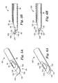
- FIG. 4A is an enlarged, perspective view of an alternative embodiment elevator tip in accordance with the present invention.
- FIG. 4B is an enlarged, cross-sectional view of FIG. 4A;
- FIG. 5A is an enlarged, perspective view of another alternative embodiment elevator tip in accordance with the present invention.
- FIG. 5B is an enlarged, cross-sectional view of FIG. 5A;
- FIG. 6A is an enlarged, perspective view of another alternative embodiment elevator tip in accordance with the present invention.
- FIG. 6B is an enlarged, cross-sectional view of FIG. 6 A.
- FIG. 1 One preferred embodiment of a surgical micro-shaving instrument or blade 10 is illustrated in FIG. 1 .
- the micro-shaving instrument 10 includes an outer blade assembly 12 and an inner blade assembly 14 .
- the outer blade assembly 12 includes an outer hub 16 and an outer tubular member 18
- the inner blade assembly 14 includes an inner hub 20 and an inner elongate member 22 (illustrated in FIG. 2 ).
- the inner elongate member 22 is sized to be coaxially received within the outer tubular member 18 .
- the micro-shaving instrument 10 is specifically configured to optimally perform an inferior turbinate reduction procedure.
- the outer tubular member 18 extends distally from the outer hub 16 .
- the outer hub 16 can assume a wide variety of forms known in the art and may, for example, form an irrigation port 24 .
- the micro-shaving instrument 10 can be configured to operate without the outer hub 16 .
- the outer tubular member 18 is an elongated, tubular body defining a proximal section 30 , an intermediate section 32 , a distal section 34 , and a central lumen 36 .
- the outer tubular member 18 is formed from a relatively rigid, surgically safe material, preferably 304 stainless steel.
- the central lumen 36 extends from the distal section 34 to the proximal section 30 .
- the distal section 34 forms a cutting window 38 (shown generally in FIG. 2) in fluid communication with the central lumen 36 .
- the proximal section 30 forms an irrigation inlet 40 in fluid communication with the central lumen 36 .
- the irrigation inlet 40 is aligned with the irrigation port 24 otherwise formed by the outer hub 16 such that fluids can be irrigated to the cutting window 38 via the central lumen 36 .
- the proximal section 30 has been depicted in FIG. 2 as having a slightly enlarged diameter to facilitate assembly to the outer hub 16 .
- the remainder of the outer tubular member 18 is preferably sized for an inferior turbinate reduction procedure.
- the intermediate section 32 as well as a majority of the distal section 34 immediately proximal the cutting window 38 , has, in one preferred embodiment, an outer diameter of 2 mm.
- the intermediate section 32 as well as a majority of the distal section 34 immediately proximal the cutting window 38 , can have an outer diameter of 2.9 mm.
- the distal section 34 forms the cutting window 38 , otherwise in fluid communication with the central lumen 36 .
- the cutting window 38 is defined by a cutting window wall 39 .
- the distal section 34 forms an elevator tip 42 extending distally from the cutting window 38 .
- the elevator tip 42 includes opposing top and bottom surfaces 44 , 46 , as best shown in FIG. 3 B.
- the surfaces 44 , 46 taper in width distally, and terminate at an end 48 that is preferably relatively sharp or blade-like.
- the end 48 serves as a blade able to easily puncture tissue upon contact therewith.
- the blade end 48 has a thickness of 0.005 inch.
- the distal section 34 preferably forms a recessed portion 50 about a majority of the cutting window 38 .
- the cutting window wall 39 is preferably formed and orientated such that the cutting window 38 extends distally in an angular fashion, whereby the distal section 34 tapers in height (relative to the horizontal orientation of FIG. 3 B).
- This angular taper of the cutting window wall 39 , and thus the cutting window 38 is represented by the angle ⁇ in FIG. 3B, whereby ⁇ is preferably in the range of approximately 10-16°, more preferably 13°.
- the recessed portion 50 is defined about the cutting window wall 39 such that the wall 39 effectively projects outwardly relative to the recessed portion 50 . This outward projection provides a distinct surface with sharp edges for engaging and/or dissecting tissue.
- the recessed portion 50 is preferably concave in shape distal the cutting window 38 , as best illustrated in FIG. 3 B.
- the top surface 44 preferably extends in a linear fashion from the recessed portion 50 , tapering in height relative to the bottom surface 46 . More particularly, a plane of the top surface 44 is preferably aligned with the plane defined by the cutting window wall 39 . Thus, relative to horizontal, the top surface 44 defines an angle corresponding with the angle ⁇ .
- the bottom surface 46 preferably curves to the end 48 .
- distal section 34 and in particular the elevator tip 42 , is but one acceptable configuration.
- distal section 60 is shown in FIGS. 4A and 4B.
- the distal section 60 forms a cutting window 62 and an elevator tip 64 distal the cutting window 62 .
- the cutting window 62 is defined by a cutting window wall 63 .
- a recessed portion 65 is formed about a majority of the wall 63 .
- the elevator tip 64 includes a proximal region 66 and a distal region 68 , with the proximal region 66 extending from the recessed portion 65 .
- the recessed portion 65 is formed about, and extends below, a majority of the cutting window wall 63 , with the cutting window wall 63 tapering distally as with the embodiment of FIG. 3 A.
- the recessed portion 65 in combination with the tapered extension of the cutting window 62 , provides for enhanced exposure of a cutting tip (not shown) otherwise disposed within the central lumen 36 upon final assembly. Further, projection of the wall 63 above the recessed portion 65 provides a distinct surface with relatively sharp edges conducive for tissue engagement.
- the proximal region 66 of the elevator tip 64 is relatively uniform in width, defined generally by a top surface 70 and a bottom surface 72 .
- the top surface 70 extends from the recessed portion 65 that is otherwise concave distal the cutting window 62 . As shown in FIG. 4B, the top surface 70 extends in an angular fashion from the recessed portion 65 , tapering in height relative to the bottom surface 72 . The angular orientation of the top surface corresponds with the angular taper defined by the cutting window wall 63 . Thus, the top surface 70 is generally aligned, or planar, with a plane defined by the cutting window wall 63 .
- the distal region 68 extends from the proximal region 66 and terminates in a blade end 80 . As best shown in FIG. 4A, the distal region 68 tapers in width, such that the blade end 80 is a relatively sharp tip capable of piercing or puncturing bodily tissue with minimal applied force. As with the proximal region 66 , the distal region 68 includes a top surface 82 and a bottom surface 84 . As best shown in FIG. 4B, the top surface 82 of the distal region 68 extends in an angular fashion, upwardly from the top surface 70 of the proximal region 66 .
- the top surface 82 of the distal region 68 and the top surface 70 of the proximal region 66 form an obtuse angle in the range of approximately 130°-160°, more preferably 147°.
- the bottom surface 84 of the distal region 68 extends from the bottom surface 72 of the proximal region 66 in a curved or arcuate fashion to the blade end 80 .
- the curved bottom surface 84 of the distal region 68 facilitates reciprocating movement of the distal section 60 within the inferior turbinate during a resecting or shaving procedure.
- FIGS. 5A and 5B Yet another alternative embodiment distal section 90 is shown in FIGS. 5A and 5B.
- the distal section 90 forms a cutting window 92 and an elevator tip 94 distal the cutting window 92 .
- the cutting window 92 is defined by a cutting window wall 96 .
- a recessed portion 98 is formed about a majority of the wall 96 , as best illustrated in FIG. SA.
- the recessed portion 98 extends only slightly distal the cutting window wall 96 .
- the distal section 90 transitions from the cutting window 92 to the elevator tip 94 immediately distal the cutting window 92 .
- the elevator tip 94 is defined by a top surface 100 and a bottom surface 102 .
- the top surface 100 is preferably concave, extending downwardly from the cutting window wall 96 .
- the downward extension of the top surface 100 corresponds with the recessed portions 50 (FIG. 3 A), 65 (FIG. 4A) previously described.
- the concave nature of the top surface 100 in combination with the distal taper of the cutting window 92 , provides for enhanced exposure of a cutting tip (not shown) otherwise disposed within the central lumen 36 upon final assembly.
- the elevator tip 94 provides additional preferred features.
- the elevator tip 94 terminates in a blade end 104 .
- the elevator tip 94 tapers distally in width, such that the blade end 104 is a relatively sharp tip capable of piercing or puncturing bodily tissue with minimal applied force.
- the bottom surface 102 is preferably curved so as to facilitate reciprocating movement of the distal section 90 within the inferior turbinate (not shown) during a resecting or shaving procedure.
- the top surface 100 is defined by opposing edges 106 .
- one or more serrations 108 are formed in the edges 106 . These serrations 108 are configured to readily resect or shave contacted tissue.
- FIGS. 6A and 6B Yet another alterative embodiment distal section 120 is shown in FIGS. 6A and 6B.
- the distal section 120 forms a cutting window 122 and an elevator tip 124 distal the cutting window 122 .
- the cutting window 122 is defined by a cutting window wall 126 .
- a recessed portion 128 is formed about a majority of the wall 126 , as best illustrated in FIGS. 6 A. Similar to the distal section 90 (FIG. 5 A and 5 B), the recessed portion 128 extends only slightly distal the cutting window wall 126 . In other words, the distal section 120 transitions from the cutting window 122 to the elevator tip 124 immediately distal the cutting window 122 . Also, as with previous embodiments, the cutting window wall 126 tapers distally relative to a central axis of the distal section 120 .
- the elevator tip 124 includes a top surface 130 and a bottom surface 132 extending along a first section 134 and a second section 136 .
- the elevator tip 124 terminates in a blade end 138 .
- the elevator tip 124 tapers distally in width, such that the blade end 138 is a relatively sharp tip capable of piercing or puncturing bodily tissue with minimal applied force.
- the top surface 130 is preferably concave, forming a depression relative to a distal end of the cutting window wall 126 .
- the top surface 130 at the first section 134 defines, in longitudinal cross-section, a concave curve having a radius of approximately 0.06 inch, although other dimensions are acceptable. Regardless, this preferred attribute provides for enhanced exposure of a cutting tip (not shown) otherwise disposed within the central lumen 36 upon final assembly.
- the bottom surface 132 is curved along the first and second sections 134 , 136 .
- the bottom surface 132 forms a concave curve in longitudinal cross-section (as shown in FIG. 6B) as the bottom surface 132 transitions from the first section 134 to the second section 136 .
- This one preferred configuration promotes advancement of the elevator tip 124 posteriorly through the inferior turbinate (not shown).
- a curve of the bottom surface 132 is such that, relative to the cross-sectional view of FIG. 6B, the bottom surface 132 elevates from the first section to the blade end 138 a preferred distance (or height) in the range of 0.056-0.06 inch, most preferably 0.058 inch.
- other dimensions can be employed.
- the distal section 34 (FIG. 3 A), 60 (FIG. 4 A), 90 (FIG. 5 A), or 120 (FIG. 6A) is formed separate from a remainder of the outer tubular member 18 (FIG. 2 ), and subsequently assembled thereto.
- the distal section 34 , 60 , 90 , 120 can be formed from a material more amenable to precise manufacturing tolerances.
- the distal section 34 , 60 , 90 , 120 is formed from heat treated, 17-4 stainless steel, whereas a remainder of outer tubular member 18 is a 304 stainless steel material.
- the so-formed distal section 34 , 60 , 90 , 120 is secured to the intermediate section 32 of the outer tubular member 18 , such as by a laser weld.
- the inner blade assembly 14 is of a type commonly known in the art, whereby the inner tubular member 22 extends from the inner hub 20 .
- the inner hub 20 is configured for selective attachment to a handpiece (not shown) that can be operated to automatically maneuver the inner blade assembly 14 during use.
- the inner tubular member 22 forms a cutting tip 150 at a distal end thereof.
- the inner tubular member 22 is coaxially disposed within the outer tubular member 18 such that the cutting tip 150 is exposed through the cutting window 38 .
- the cutting tip 150 can assume a wide variety of forms, and preferably forms a series of teeth or cutting edges designed to engage and resect (or shave) tissue.
- the surgical micro-shaving instrument 10 of the present invention is particularly useful for an inferior turbinate reduction procedure.
- the assembled instrument 10 is deployed to the sinus cavity, with the blade end 48 (FIG. 3 A), 80 (FIG. 4 A), 104 (FIG. 5 A), or 138 (FIG. 6A) being inserted into the anterior face of the inferior turbinate just medial to the muco-cutaneous junction.
- the blade end 48 , 80 , 104 , or 138 is then firmly pushed towards the turbinate bone, piercing through the turbinate mucosa.
- the blade end 48 , 80 , 104 , 138 is relatively sharp, the tissue is readily punctured, in direct contrast to blunt-ended instruments currently available.
- the distal section 34 (FIG. 3 A), 60 (FIG. 4 A), 90 (FIG. 5 A), 120 (FIG. 6A) is then moved in a posterior fashion to resect submucous of the inferior turbinate.
- a sub-mucosal pocket is dissected by tunneling the distal section 34 , 60 , 90 , 120 in an anterior to posterior and superior to inferior sweeping motion.
- tissue resection is initiated, preferably with the cutting tip 150 facing laterally and moving back and forth in a sweeping motion analogous to liposuction.
- both the cutting tip 150 of the inner tubular member 22 as well as the cutting window wall 39 (FIG. 3 A), 63 (FIG. 4 A), 96 (FIG. 5 A), or 122 (FIG. 6A) that otherwise projects relative to a remainder of the elevator tip 42 (FIG. 3 A), 64 (FIG. 4 A), or 94 (FIG. 5 A), or 124 (FIG. 6 A), respectively, assist in engaging and resecting contacted tissue. Further, with the embodiment of FIGS.
- the serrations 108 formed by the edges 106 further assist in engaging and resecting contacted tissue.
- the elevator tip 42 , 64 , 94 , 124 dissects tissue away from the bone inside of the turbinate, so that the cutting tip 150 of the inner tubular member 22 can more easily contact, and therefore resect or shave, desired tissue.
- the handpiece (not shown) is operated to cause the cutting tip 150 to rapidly resect or shave the contacted tissue, with the removed tissue being suctioned away from the target site.
- the surgical micro-shaving instrument of the present invention provides a marked improvement over previous designs.
- use of a micro-shaving tool provides a distinct advantage over other available techniques (such as cryosurgery, electrocautery, laser, etc.) as the tool does not destroy mucousa in order to access the submucous tissue to be resected.
- the elevator tip associated with the present invention readily pierces the inferior turbinate, as well as dissecting targeted tissue away from the turbinate bone, thereby promoting more efficient and effective cutting.
Landscapes
- Health & Medical Sciences (AREA)
- Surgery (AREA)
- Life Sciences & Earth Sciences (AREA)
- Biomedical Technology (AREA)
- Nuclear Medicine, Radiotherapy & Molecular Imaging (AREA)
- Engineering & Computer Science (AREA)
- Orthopedic Medicine & Surgery (AREA)
- Heart & Thoracic Surgery (AREA)
- Medical Informatics (AREA)
- Molecular Biology (AREA)
- Animal Behavior & Ethology (AREA)
- General Health & Medical Sciences (AREA)
- Public Health (AREA)
- Veterinary Medicine (AREA)
- Surgical Instruments (AREA)
Abstract
Description
Claims (20)
Priority Applications (8)
| Application Number | Priority Date | Filing Date | Title |
|---|---|---|---|
| US09/839,319 US6503263B2 (en) | 2000-09-24 | 2001-04-20 | Surgical micro-shaving instrument with elevator tip |
| JP2002528125A JP2004510469A (en) | 2000-09-24 | 2001-09-24 | Endoscopic cutting machine |
| ES01973400T ES2323943T3 (en) | 2000-09-24 | 2001-09-24 | ENDOSCOPIC TRASURATOR. |
| EP01973400A EP1322240B1 (en) | 2000-09-24 | 2001-09-24 | Endoscopic shaver |
| PCT/US2001/029730 WO2002024084A1 (en) | 2000-09-24 | 2001-09-24 | Endoscopic shaver |
| DE60138291T DE60138291D1 (en) | 2000-09-24 | 2001-09-24 | ENDOSCOPIC STENCIL BLADES |
| AT01973400T ATE427705T1 (en) | 2000-09-24 | 2001-09-24 | ENDOSCOPIC SCAPER BLADE |
| JP2012073745A JP5738230B2 (en) | 2000-09-24 | 2012-03-28 | Endoscopic cutting machine |
Applications Claiming Priority (2)
| Application Number | Priority Date | Filing Date | Title |
|---|---|---|---|
| US23522000P | 2000-09-24 | 2000-09-24 | |
| US09/839,319 US6503263B2 (en) | 2000-09-24 | 2001-04-20 | Surgical micro-shaving instrument with elevator tip |
Publications (2)
| Publication Number | Publication Date |
|---|---|
| US20020038130A1 US20020038130A1 (en) | 2002-03-28 |
| US6503263B2 true US6503263B2 (en) | 2003-01-07 |
Family
ID=26928691
Family Applications (1)
| Application Number | Title | Priority Date | Filing Date |
|---|---|---|---|
| US09/839,319 Expired - Lifetime US6503263B2 (en) | 2000-09-24 | 2001-04-20 | Surgical micro-shaving instrument with elevator tip |
Country Status (7)
| Country | Link |
|---|---|
| US (1) | US6503263B2 (en) |
| EP (1) | EP1322240B1 (en) |
| JP (2) | JP2004510469A (en) |
| AT (1) | ATE427705T1 (en) |
| DE (1) | DE60138291D1 (en) |
| ES (1) | ES2323943T3 (en) |
| WO (1) | WO2002024084A1 (en) |
Cited By (94)
| Publication number | Priority date | Publication date | Assignee | Title |
|---|---|---|---|---|
| WO2003041597A1 (en) * | 2001-11-15 | 2003-05-22 | Expanding Concepts, L.L.C. | Percutaneous cellulite removal system |
| US20030167053A1 (en) * | 2000-05-31 | 2003-09-04 | Taufig Ahmmed Ziah | Liposuction device |
| US20040006379A1 (en) * | 2000-10-06 | 2004-01-08 | Expanding Concepts, L.L.C. | Epidural thermal posterior annuloplasty |
| US20040236313A1 (en) * | 2003-05-21 | 2004-11-25 | Klein Jeffrey A. | Infiltration cannula |
| US20050054972A1 (en) * | 2003-09-09 | 2005-03-10 | Adams Kenneth M. | Surgical micro-burring instrument and method of performing sinus surgery |
| US20050165345A1 (en) * | 2001-06-06 | 2005-07-28 | Laufer Michael D. | Fat removal and nerve protection device and method |
| US20060063973A1 (en) * | 2004-04-21 | 2006-03-23 | Acclarent, Inc. | Methods and apparatus for treating disorders of the ear, nose and throat |
| US20070063687A1 (en) * | 2005-09-20 | 2007-03-22 | Dacheng Zhou | Circuit and method for bias voltage generation |
| US20070129751A1 (en) * | 2004-04-21 | 2007-06-07 | Acclarent, Inc. | Devices, systems and methods useable for treating frontal sinusitis |
| US20070135789A1 (en) * | 2004-04-21 | 2007-06-14 | Acclarent, Inc. | Use of mechanical dilator devices to enlarge ostia of paranasal sinuses and other passages in the ear, nose, throat and paranasal sinuses |
| US20070208301A1 (en) * | 2005-06-10 | 2007-09-06 | Acclarent, Inc. | Catheters with non-removable guide members useable for treatment of sinusitis |
| US20070208252A1 (en) * | 2004-04-21 | 2007-09-06 | Acclarent, Inc. | Systems and methods for performing image guided procedures within the ear, nose, throat and paranasal sinuses |
| US20070249896A1 (en) * | 2004-04-21 | 2007-10-25 | Eric Goldfarb | Endoscopic methods and devices for transnasal procedures |
| US20070293727A1 (en) * | 2004-04-21 | 2007-12-20 | Acclarent, Inc. | Endoscopic methods and devices for transnasal procedures |
| US20080287908A1 (en) * | 2004-04-21 | 2008-11-20 | Acclarent, Inc. | Ethmoidotomy System and Implantable Spacer Devices Having Therapeutic Substance Delivery Capability for Treatment of Paranasal Sinusitis |
| US20090124975A1 (en) * | 2007-11-12 | 2009-05-14 | Oliver Dana A | Systems and methods for surgical removal of brain tumors |
| US20090187098A1 (en) * | 2004-04-21 | 2009-07-23 | Acclarent, Inc. | Devices, Systems and Methods for Diagnosing and Treating Sinusitis and Other Disorders of the Ears, Nose, and/or Throat |
| US20090198216A1 (en) * | 2004-04-21 | 2009-08-06 | Acclarent, Inc. | Frontal sinus spacer |
| US20090248019A1 (en) * | 2008-03-31 | 2009-10-01 | Applied Medical Resources Corporation | Electrosurgical system |
| US20090287143A1 (en) * | 2008-05-15 | 2009-11-19 | Casey Line | Small Gauge Mechanical Tissue Cutter/Aspirator Probe For Glaucoma Surgery |
| US20090287233A1 (en) * | 2008-05-15 | 2009-11-19 | Huculak John C | Small Gauge Mechanical Tissue Cutter/Aspirator Probe For Glaucoma Surgery |
| US20090312745A1 (en) * | 2004-04-21 | 2009-12-17 | Acclarent, Inc. | Systems and methods for transnasal dilation of passageways in the ear, nose or throat |
| US20100312252A1 (en) * | 2009-06-03 | 2010-12-09 | Guangyao Jia | Capsularhexis device with flexible heating element having an angled transitional neck |
| US20100312232A1 (en) * | 2009-06-03 | 2010-12-09 | Guangyao Jia | Capsulotomy Repair Device and Method for Capsulotomy Repair |
| US20110112512A1 (en) * | 2004-04-21 | 2011-05-12 | Acclarent, Inc. | Devices and methods for treating maxillary sinus disease |
| US20110202049A1 (en) * | 2010-02-18 | 2011-08-18 | Alcon Research, Ltd. | Small Gauge Ablation Probe For Glaucoma Surgery |
| US8137344B2 (en) | 2008-12-10 | 2012-03-20 | Alcon Research, Ltd. | Flexible, automated capsulorhexis device |
| US20120078277A1 (en) * | 2009-01-28 | 2012-03-29 | Medtronic Xomed, Inc. | Systems and methods for surgical removal of brain tumors |
| US8157797B2 (en) | 2009-01-12 | 2012-04-17 | Alcon Research, Ltd. | Capsularhexis device with retractable bipolar electrodes |
| US8702626B1 (en) | 2004-04-21 | 2014-04-22 | Acclarent, Inc. | Guidewires for performing image guided procedures |
| US20140148729A1 (en) * | 2012-11-29 | 2014-05-29 | Gregory P. Schmitz | Micro-mechanical devices and methods for brain tumor removal |
| USD707818S1 (en) | 2013-03-05 | 2014-06-24 | Alcon Research Ltd. | Capsulorhexis handpiece |
| US8764709B2 (en) | 2004-04-21 | 2014-07-01 | Acclarent, Inc. | Devices, systems and methods for treating disorders of the ear, nose and throat |
| US8764786B2 (en) | 2002-09-30 | 2014-07-01 | Acclarent, Inc. | Balloon catheters and methods for treating paranasal sinuses |
| US8777926B2 (en) | 2004-04-21 | 2014-07-15 | Acclarent, Inc. | Apparatus and methods for dilating and modifying ostia of paranasal sinuses and other intranasel or paranasal structures |
| US8870893B2 (en) | 2004-04-21 | 2014-10-28 | Acclarent, Inc. | Devices, systems and methods for diagnosing and treating sinusitis and other disorders of the ears, nose and/or throat |
| US8932276B1 (en) | 2004-04-21 | 2015-01-13 | Acclarent, Inc. | Shapeable guide catheters and related methods |
| US8957060B2 (en) | 2009-11-30 | 2015-02-17 | Jeffrey Alan KLEIN | Tumescent antibiotic solution |
| US8968269B2 (en) | 2005-09-23 | 2015-03-03 | Acclarent, Inc. | Multi-conduit balloon catheter |
| US9072626B2 (en) | 2009-03-31 | 2015-07-07 | Acclarent, Inc. | System and method for treatment of non-ventilating middle ear by providing a gas pathway through the nasopharynx |
| USD737438S1 (en) | 2014-03-04 | 2015-08-25 | Novartis Ag | Capsulorhexis handpiece |
| US9125720B2 (en) | 2008-10-13 | 2015-09-08 | Alcon Research, Ltd. | Capsularhexis device with flexible heating element |
| US9149388B2 (en) | 2010-09-29 | 2015-10-06 | Alcon Research, Ltd. | Attenuated RF power for automated capsulorhexis |
| US9179823B2 (en) | 2006-09-15 | 2015-11-10 | Acclarent, Inc. | Methods and devices for facilitating visualization in a surgical environment |
| US9226792B2 (en) | 2012-06-12 | 2016-01-05 | Medtronic Advanced Energy Llc | Debridement device and method |
| US9241755B2 (en) | 2010-05-11 | 2016-01-26 | Alcon Research, Ltd. | Capsule polishing device and method for capsule polishing |
| USD748259S1 (en) | 2014-12-29 | 2016-01-26 | Applied Medical Resources Corporation | Electrosurgical instrument |
| US9241734B2 (en) | 2012-12-12 | 2016-01-26 | Covidien Lp | Tissue-removing catheter including screw blade and cutter driveshaft |
| US9290854B2 (en) | 2013-07-16 | 2016-03-22 | Microfabrica Inc. | Counterfeiting deterrent and security devices, systems and methods |
| US9308361B2 (en) | 2005-01-18 | 2016-04-12 | Acclarent, Inc. | Implantable devices and methods for treating sinusitis and other disorders |
| US9320563B2 (en) | 2010-10-01 | 2016-04-26 | Applied Medical Resources Corporation | Electrosurgical instruments and connections thereto |
| US9451977B2 (en) | 2008-06-23 | 2016-09-27 | Microfabrica Inc. | MEMS micro debrider devices and methods of tissue removal |
| US9463068B2 (en) | 2007-05-08 | 2016-10-11 | Acclarent, Inc. | Methods and devices for protecting nasal turbinates |
| US9468362B2 (en) | 2004-04-21 | 2016-10-18 | Acclarent, Inc. | Endoscopic methods and devices for transnasal procedures |
| US9532797B2 (en) | 2012-12-12 | 2017-01-03 | Covidien Lp | Tissue-removing catheter including urging mechanism |
| US9549718B2 (en) | 2012-12-12 | 2017-01-24 | Covidien Lp | Tissue-removing catheter for body lumen |
| US9549755B2 (en) | 2012-12-12 | 2017-01-24 | Covidien Lp | Cutter for tissue-removing catheter |
| US9629684B2 (en) | 2013-03-15 | 2017-04-25 | Acclarent, Inc. | Apparatus and method for treatment of ethmoid sinusitis |
| US9636139B2 (en) | 2012-12-12 | 2017-05-02 | Covidien Lp | Tissue-removing catheter with ball and socket deployment mechanism |
| US9636258B2 (en) | 2009-03-31 | 2017-05-02 | Acclarent, Inc. | System and method for treatment of non-ventilating middle ear by providing a gas pathway through the nasopharynx |
| US9636138B2 (en) | 2012-12-12 | 2017-05-02 | Covidien Lp | Tissue-removing catheter including force-transmitting member for actuating a cutter housing |
| US9750401B2 (en) | 2008-07-30 | 2017-09-05 | Acclarent, Inc. | Paranasal ostium finder devices and methods |
| US9814484B2 (en) | 2012-11-29 | 2017-11-14 | Microfabrica Inc. | Micro debrider devices and methods of tissue removal |
| US9820688B2 (en) | 2006-09-15 | 2017-11-21 | Acclarent, Inc. | Sinus illumination lightwire device |
| US9826999B2 (en) | 2004-04-21 | 2017-11-28 | Acclarent, Inc. | Methods and apparatus for treating disorders of the ear nose and throat |
| US9861793B2 (en) | 2008-03-10 | 2018-01-09 | Acclarent, Inc. | Corewire design and construction for medical devices |
| US9907564B2 (en) | 2008-06-23 | 2018-03-06 | Microfabrica Inc. | Miniature shredding tool for use in medical applications and methods for making |
| US10064644B2 (en) | 2008-06-23 | 2018-09-04 | Microfabrica Inc. | Selective tissue removal tool for use in medical applications and methods for making and using |
| US10149713B2 (en) | 2014-05-16 | 2018-12-11 | Applied Medical Resources Corporation | Electrosurgical system |
| US10188456B2 (en) | 2015-02-18 | 2019-01-29 | Medtronic Xomed, Inc. | Electrode assembly for RF energy enabled tissue debridement device |
| US10188413B1 (en) | 2004-04-21 | 2019-01-29 | Acclarent, Inc. | Deflectable guide catheters and related methods |
| US10206821B2 (en) | 2007-12-20 | 2019-02-19 | Acclarent, Inc. | Eustachian tube dilation balloon with ventilation path |
| US10314647B2 (en) | 2013-12-23 | 2019-06-11 | Medtronic Advanced Energy Llc | Electrosurgical cutting instrument |
| US10376302B2 (en) | 2015-02-18 | 2019-08-13 | Medtronic Xomed, Inc. | Rotating electrical connector for RF energy enabled tissue debridement device |
| US10420603B2 (en) | 2014-12-23 | 2019-09-24 | Applied Medical Resources Corporation | Bipolar electrosurgical sealer and divider |
| US10456161B2 (en) | 2016-04-14 | 2019-10-29 | Covidien Lp | Tissue-removing catheter with adjustment mechanism |
| US10492822B2 (en) | 2009-08-18 | 2019-12-03 | Microfabrica Inc. | Concentric cutting devices for use in minimally invasive medical procedures |
| US10676836B2 (en) | 2003-06-27 | 2020-06-09 | Microfabrica Inc. | Electrochemical fabrication methods incorporating dielectric materials and/or using dielectric substrates |
| US10792092B2 (en) | 2014-05-30 | 2020-10-06 | Applied Medical Resources Corporation | Electrosurgical seal and dissection systems |
| US10813686B2 (en) | 2014-02-26 | 2020-10-27 | Medtronic Advanced Energy Llc | Electrosurgical cutting instrument |
| US10849645B2 (en) | 2016-11-23 | 2020-12-01 | Corit Llc | Apparatus and methods for tissue reduction |
| US10874838B2 (en) | 2004-04-21 | 2020-12-29 | Acclarent, Inc. | Systems and methods for transnasal dilation of passageways in the ear, nose or throat |
| US10874290B2 (en) | 2015-02-26 | 2020-12-29 | Stryker Corporation | Surgical instrument with articulation region |
| US10939934B2 (en) | 2008-06-23 | 2021-03-09 | Microfabrica Inc. | Miniature shredding tools for use in medical applications, methods for making, and procedures for using |
| US11020139B2 (en) | 2016-07-14 | 2021-06-01 | Stryker European Holdings I, Llc | Cutting assembly for surgical instrument with clog reducing tip |
| US11207130B2 (en) | 2015-02-18 | 2021-12-28 | Medtronic Xomed, Inc. | RF energy enabled tissue debridement device |
| US11234760B2 (en) | 2012-10-05 | 2022-02-01 | Medtronic Advanced Energy Llc | Electrosurgical device for cutting and removing tissue |
| US11357516B2 (en) * | 2015-07-09 | 2022-06-14 | Carevature Medical Ltd. | Abrasive cutting surgical instrument |
| US11413051B2 (en) | 2017-07-25 | 2022-08-16 | Stryker European Holdings I Llc | Irrigation sleeves for use with surgical systems |
| US11529502B2 (en) | 2004-04-21 | 2022-12-20 | Acclarent, Inc. | Apparatus and methods for dilating and modifying ostia of paranasal sinuses and other intranasal or paranasal structures |
| US11696796B2 (en) | 2018-11-16 | 2023-07-11 | Applied Medical Resources Corporation | Electrosurgical system |
| US11793536B2 (en) | 2014-04-17 | 2023-10-24 | Stryker Corporation | Surgical tool having cables for selectively steering and locking a shaft in a bend |
| US11864812B2 (en) | 2018-09-05 | 2024-01-09 | Applied Medical Resources Corporation | Electrosurgical generator control system |
| US12082840B2 (en) | 2015-06-17 | 2024-09-10 | Stryker European Operations Holdings Llc | Surgical instrument with tip for resection of tissue with combined longitudinal and torsional vibration |
Families Citing this family (20)
| Publication number | Priority date | Publication date | Assignee | Title |
|---|---|---|---|---|
| DE10105592A1 (en) | 2001-02-06 | 2002-08-08 | Achim Goepferich | Placeholder for drug release in the frontal sinus |
| US6676677B2 (en) * | 2001-05-11 | 2004-01-13 | Jeffrey A. Klein | Liposuction cannula with abrading apertures |
| US20040243151A1 (en) * | 2003-04-29 | 2004-12-02 | Demmy Todd L. | Surgical stapling device with dissecting tip |
| US20040236307A1 (en) * | 2003-05-21 | 2004-11-25 | Klein Jeffrey A. | Infiltration cannula |
| FR2873282B1 (en) * | 2004-07-23 | 2007-04-13 | Hacene Zerazhi | TROCART FOR OSTEO-MEDIUM BIOPSY |
| US7927361B2 (en) * | 2005-11-29 | 2011-04-19 | Medtronic Xomed, Inc. | Method and apparatus for removing material from an intervertebral disc space, such as in performing a nucleotomy |
| US8439687B1 (en) | 2006-12-29 | 2013-05-14 | Acclarent, Inc. | Apparatus and method for simulated insertion and positioning of guidewares and other interventional devices |
| US8118757B2 (en) | 2007-04-30 | 2012-02-21 | Acclarent, Inc. | Methods and devices for ostium measurement |
| NL1034654C2 (en) * | 2007-11-08 | 2009-05-11 | D O R C Dutch Ophthalmic Res C | Eye surgery tool, has tube including slot-shaped opening that is cooperated with cutters for cutting and extraction of tissue, where surface of closed end of tube is situated at specific angle to longitudinal axis of tube |
| US20090163890A1 (en) * | 2007-12-20 | 2009-06-25 | Acclarent, Inc. | Method and System for Accessing, Diagnosing and Treating Target Tissue Regions Within the Middle Ear and the Eustachian Tube |
| JP5430161B2 (en) * | 2008-06-19 | 2014-02-26 | オリンパスメディカルシステムズ株式会社 | Ultrasonic surgical device |
| US8444648B2 (en) | 2009-09-17 | 2013-05-21 | The Anspach Effort, Inc. | Surgical file |
| US8414606B2 (en) | 2010-10-22 | 2013-04-09 | Medtronic Xomed, Inc. | Method and apparatus for removing material from an intervertebral disc space and preparing end plates |
| US9433437B2 (en) | 2013-03-15 | 2016-09-06 | Acclarent, Inc. | Apparatus and method for treatment of ethmoid sinusitis |
| JP6276987B2 (en) * | 2013-12-26 | 2018-02-07 | 株式会社貝印刃物開発センター | Trocar |
| US10537336B2 (en) | 2016-09-28 | 2020-01-21 | Gyrus Acmi, Inc. | Electromechanical slider valve suction controller |
| CN106890020A (en) * | 2017-02-21 | 2017-06-27 | 江苏水木天蓬科技有限公司 | A kind of ultrasound knife cutter head |
| GB2570687B (en) * | 2018-02-02 | 2022-09-28 | Gyrus Medical Ltd | Surgical shaving instruments |
| CN109717924A (en) * | 2019-01-31 | 2019-05-07 | 重庆市第四人民医院 | Ligamentum flavum Knife for stripping cable |
| US12433669B2 (en) | 2019-03-07 | 2025-10-07 | Procept Biorobotics Corporation | Material removal from surgical site |
Citations (20)
| Publication number | Priority date | Publication date | Assignee | Title |
|---|---|---|---|---|
| US3844272A (en) * | 1969-02-14 | 1974-10-29 | A Banko | Surgical instruments |
| US4368734A (en) | 1978-01-27 | 1983-01-18 | Surgical Design Corp. | Surgical instrument |
| US4530356A (en) | 1983-02-08 | 1985-07-23 | Helfgott Maxwell A | Ophthalmic surgical instrument with beveled tip |
| US4649919A (en) * | 1985-01-23 | 1987-03-17 | Precision Surgical Instruments, Inc. | Surgical instrument |
| GB2205045A (en) | 1987-05-27 | 1988-11-30 | Wolf Gmbh Richard | An instrument for the surgical treatment of pieces of tissue |
| US4834729A (en) * | 1986-12-30 | 1989-05-30 | Dyonics, Inc. | Arthroscopic surgical instrument |
| US4850354A (en) | 1987-08-13 | 1989-07-25 | Baxter Travenol Laboratories, Inc. | Surgical cutting instrument |
| US4986825A (en) * | 1988-10-11 | 1991-01-22 | Concept, Inc. | Surgical cutting instrument |
| US5320635A (en) | 1990-10-19 | 1994-06-14 | Smith & Nephew Dyonics, Inc. | Surgical device with surgical element removably connected to drive element |
| US5685838A (en) | 1995-04-17 | 1997-11-11 | Xomed-Treace, Inc. | Sinus debrider apparatus |
| US5695511A (en) | 1994-11-29 | 1997-12-09 | Metamorphic Surgical Devices | Surgical instruments for minimally invasive procedures |
| US5735792A (en) | 1992-11-25 | 1998-04-07 | Clarus Medical Systems, Inc. | Surgical instrument including viewing optics and an atraumatic probe |
| US5741287A (en) | 1996-11-01 | 1998-04-21 | Femrx, Inc. | Surgical tubular cutter having a tapering cutting chamber |
| US5916231A (en) | 1996-09-24 | 1999-06-29 | Xomed Surgical Products, Inc. | Powered handpiece and surgical blades and methods therefor |
| US5922003A (en) | 1997-05-09 | 1999-07-13 | Xomed Surgical Products, Inc. | Angled rotary tissue cutting instrument and method of fabricating the same |
| US5925056A (en) | 1996-04-12 | 1999-07-20 | Surgical Dynamics, Inc. | Surgical cutting device removably connected to a rotary drive element |
| US5964777A (en) * | 1997-12-11 | 1999-10-12 | Smith & Nephew, Inc. | Surgical cutting instrument |
| US6001116A (en) | 1996-04-10 | 1999-12-14 | Linvatec Corporation | Endoscopic shaver blade with resilient cutting edges |
| US6068641A (en) * | 1998-08-25 | 2000-05-30 | Linvatec Corporation | Irrigated burr |
| US6101477A (en) | 1998-01-23 | 2000-08-08 | American Express Travel Related Services Company, Inc. | Methods and apparatus for a travel-related multi-function smartcard |
Family Cites Families (3)
| Publication number | Priority date | Publication date | Assignee | Title |
|---|---|---|---|---|
| US4111207A (en) * | 1976-10-28 | 1978-09-05 | David Kopf Instruments | Notched tubular cutting instrument |
| US5269798A (en) * | 1992-02-19 | 1993-12-14 | Linvatec Corporation | Surgical cutting instrument with movable, inner and outer tubular members |
| JPH10137248A (en) * | 1996-11-13 | 1998-05-26 | Olympus Optical Co Ltd | Suction biopsy tool |
-
2001
- 2001-04-20 US US09/839,319 patent/US6503263B2/en not_active Expired - Lifetime
- 2001-09-24 ES ES01973400T patent/ES2323943T3/en not_active Expired - Lifetime
- 2001-09-24 EP EP01973400A patent/EP1322240B1/en not_active Expired - Lifetime
- 2001-09-24 WO PCT/US2001/029730 patent/WO2002024084A1/en not_active Ceased
- 2001-09-24 JP JP2002528125A patent/JP2004510469A/en not_active Withdrawn
- 2001-09-24 AT AT01973400T patent/ATE427705T1/en not_active IP Right Cessation
- 2001-09-24 DE DE60138291T patent/DE60138291D1/en not_active Expired - Lifetime
-
2012
- 2012-03-28 JP JP2012073745A patent/JP5738230B2/en not_active Expired - Lifetime
Patent Citations (22)
| Publication number | Priority date | Publication date | Assignee | Title |
|---|---|---|---|---|
| US3844272A (en) * | 1969-02-14 | 1974-10-29 | A Banko | Surgical instruments |
| US4368734A (en) | 1978-01-27 | 1983-01-18 | Surgical Design Corp. | Surgical instrument |
| US4530356A (en) | 1983-02-08 | 1985-07-23 | Helfgott Maxwell A | Ophthalmic surgical instrument with beveled tip |
| US4649919A (en) * | 1985-01-23 | 1987-03-17 | Precision Surgical Instruments, Inc. | Surgical instrument |
| US4834729A (en) * | 1986-12-30 | 1989-05-30 | Dyonics, Inc. | Arthroscopic surgical instrument |
| GB2205045A (en) | 1987-05-27 | 1988-11-30 | Wolf Gmbh Richard | An instrument for the surgical treatment of pieces of tissue |
| US4850354A (en) | 1987-08-13 | 1989-07-25 | Baxter Travenol Laboratories, Inc. | Surgical cutting instrument |
| US4986825A (en) * | 1988-10-11 | 1991-01-22 | Concept, Inc. | Surgical cutting instrument |
| US5320635A (en) | 1990-10-19 | 1994-06-14 | Smith & Nephew Dyonics, Inc. | Surgical device with surgical element removably connected to drive element |
| US5735792A (en) | 1992-11-25 | 1998-04-07 | Clarus Medical Systems, Inc. | Surgical instrument including viewing optics and an atraumatic probe |
| US5695511A (en) | 1994-11-29 | 1997-12-09 | Metamorphic Surgical Devices | Surgical instruments for minimally invasive procedures |
| US5685838A (en) | 1995-04-17 | 1997-11-11 | Xomed-Treace, Inc. | Sinus debrider apparatus |
| US5957881A (en) | 1995-04-17 | 1999-09-28 | Xomed Surgical Products, Inc. | Sinus debrider apparatus |
| US6001116A (en) | 1996-04-10 | 1999-12-14 | Linvatec Corporation | Endoscopic shaver blade with resilient cutting edges |
| US5925056A (en) | 1996-04-12 | 1999-07-20 | Surgical Dynamics, Inc. | Surgical cutting device removably connected to a rotary drive element |
| US5916231A (en) | 1996-09-24 | 1999-06-29 | Xomed Surgical Products, Inc. | Powered handpiece and surgical blades and methods therefor |
| US5957945A (en) | 1996-09-24 | 1999-09-28 | Xomed Surgical Products, Inc. | Powered handpiece system |
| US5741287A (en) | 1996-11-01 | 1998-04-21 | Femrx, Inc. | Surgical tubular cutter having a tapering cutting chamber |
| US5922003A (en) | 1997-05-09 | 1999-07-13 | Xomed Surgical Products, Inc. | Angled rotary tissue cutting instrument and method of fabricating the same |
| US5964777A (en) * | 1997-12-11 | 1999-10-12 | Smith & Nephew, Inc. | Surgical cutting instrument |
| US6101477A (en) | 1998-01-23 | 2000-08-08 | American Express Travel Related Services Company, Inc. | Methods and apparatus for a travel-related multi-function smartcard |
| US6068641A (en) * | 1998-08-25 | 2000-05-30 | Linvatec Corporation | Irrigated burr |
Cited By (214)
| Publication number | Priority date | Publication date | Assignee | Title |
|---|---|---|---|---|
| US20030167053A1 (en) * | 2000-05-31 | 2003-09-04 | Taufig Ahmmed Ziah | Liposuction device |
| US6902559B2 (en) * | 2000-05-31 | 2005-06-07 | Ahmmed Ziah Taufig | Liposuction device |
| US20040006379A1 (en) * | 2000-10-06 | 2004-01-08 | Expanding Concepts, L.L.C. | Epidural thermal posterior annuloplasty |
| US20050165345A1 (en) * | 2001-06-06 | 2005-07-28 | Laufer Michael D. | Fat removal and nerve protection device and method |
| US8052672B2 (en) * | 2001-06-06 | 2011-11-08 | LENR Solutions, Inc. | Fat removal and nerve protection device and method |
| US20030158566A1 (en) * | 2001-11-15 | 2003-08-21 | Expanding Concepts, L.L.C. | Percutaneous cellulite removal system |
| WO2003041597A1 (en) * | 2001-11-15 | 2003-05-22 | Expanding Concepts, L.L.C. | Percutaneous cellulite removal system |
| US20050131439A1 (en) * | 2001-11-15 | 2005-06-16 | Expanding Concepts, L.L.C. | Percutaneous cellulite removal system |
| US6916328B2 (en) | 2001-11-15 | 2005-07-12 | Expanding Concepts, L.L.C | Percutaneous cellulite removal system |
| US8764786B2 (en) | 2002-09-30 | 2014-07-01 | Acclarent, Inc. | Balloon catheters and methods for treating paranasal sinuses |
| US9457175B2 (en) | 2002-09-30 | 2016-10-04 | Acclarent, Inc. | Balloon catheters and methods for treating paranasal sinuses |
| US20040236313A1 (en) * | 2003-05-21 | 2004-11-25 | Klein Jeffrey A. | Infiltration cannula |
| US10676836B2 (en) | 2003-06-27 | 2020-06-09 | Microfabrica Inc. | Electrochemical fabrication methods incorporating dielectric materials and/or using dielectric substrates |
| US20050054972A1 (en) * | 2003-09-09 | 2005-03-10 | Adams Kenneth M. | Surgical micro-burring instrument and method of performing sinus surgery |
| AU2004271977B2 (en) * | 2003-09-09 | 2010-06-24 | Medtronic Xomed, Inc. | Surgical micro-burring instrument and method of performing sinus surgery |
| US8313489B2 (en) | 2003-09-09 | 2012-11-20 | Medtronic Xomed, Inc. | Surgical micro-burring instrument and method of performing sinus surgery |
| AU2010207765B2 (en) * | 2003-09-09 | 2011-09-15 | Medtronic Xomed, Inc. | Surgical micro-burring instrument and method of performing sinus surgery |
| US7785337B2 (en) | 2003-09-09 | 2010-08-31 | Medtronic Xomed, Inc. | Surgical micro-burring instrument and method of performing sinus surgery |
| US10779752B2 (en) | 2004-04-21 | 2020-09-22 | Acclarent, Inc. | Guidewires for performing image guided procedures |
| US10441758B2 (en) | 2004-04-21 | 2019-10-15 | Acclarent, Inc. | Frontal sinus spacer |
| US11589742B2 (en) | 2004-04-21 | 2023-02-28 | Acclarent, Inc. | Methods and apparatus for treating disorders of the ear nose and throat |
| US20090187098A1 (en) * | 2004-04-21 | 2009-07-23 | Acclarent, Inc. | Devices, Systems and Methods for Diagnosing and Treating Sinusitis and Other Disorders of the Ears, Nose, and/or Throat |
| US20090198216A1 (en) * | 2004-04-21 | 2009-08-06 | Acclarent, Inc. | Frontal sinus spacer |
| US11529502B2 (en) | 2004-04-21 | 2022-12-20 | Acclarent, Inc. | Apparatus and methods for dilating and modifying ostia of paranasal sinuses and other intranasal or paranasal structures |
| US11511090B2 (en) | 2004-04-21 | 2022-11-29 | Acclarent, Inc. | Devices, systems and methods useable for treating sinusitis |
| US11202644B2 (en) | 2004-04-21 | 2021-12-21 | Acclarent, Inc. | Shapeable guide catheters and related methods |
| US11065061B2 (en) | 2004-04-21 | 2021-07-20 | Acclarent, Inc. | Systems and methods for performing image guided procedures within the ear, nose, throat and paranasal sinuses |
| US20090312745A1 (en) * | 2004-04-21 | 2009-12-17 | Acclarent, Inc. | Systems and methods for transnasal dilation of passageways in the ear, nose or throat |
| US20100042046A1 (en) * | 2004-04-21 | 2010-02-18 | Acclarent, Inc. | Devices, systems and methods useable for treating sinusitis |
| US20080125626A1 (en) * | 2004-04-21 | 2008-05-29 | Acclarent, Inc. | Devices, Systems and Methods Useable for Treating Sinusitis |
| US20100174308A1 (en) * | 2004-04-21 | 2010-07-08 | Acclarent, Inc. | Devices, systems and methods useable for treating sinusitis |
| US20070293727A1 (en) * | 2004-04-21 | 2007-12-20 | Acclarent, Inc. | Endoscopic methods and devices for transnasal procedures |
| US11019989B2 (en) | 2004-04-21 | 2021-06-01 | Acclarent, Inc. | Methods and apparatus for treating disorders of the ear nose and throat |
| US11020136B2 (en) | 2004-04-21 | 2021-06-01 | Acclarent, Inc. | Deflectable guide catheters and related methods |
| US20110060214A1 (en) * | 2004-04-21 | 2011-03-10 | Acclarent, Inc. | Systems and Methods for Performing Image Guided Procedures Within the Ear, Nose, Throat and Paranasal Sinuses |
| US20110112512A1 (en) * | 2004-04-21 | 2011-05-12 | Acclarent, Inc. | Devices and methods for treating maxillary sinus disease |
| US10874838B2 (en) | 2004-04-21 | 2020-12-29 | Acclarent, Inc. | Systems and methods for transnasal dilation of passageways in the ear, nose or throat |
| US20070249896A1 (en) * | 2004-04-21 | 2007-10-25 | Eric Goldfarb | Endoscopic methods and devices for transnasal procedures |
| US20070208252A1 (en) * | 2004-04-21 | 2007-09-06 | Acclarent, Inc. | Systems and methods for performing image guided procedures within the ear, nose, throat and paranasal sinuses |
| US10856727B2 (en) | 2004-04-21 | 2020-12-08 | Acclarent, Inc. | Endoscopic methods and devices for transnasal procedures |
| US10806477B2 (en) | 2004-04-21 | 2020-10-20 | Acclarent, Inc. | Systems and methods for transnasal dilation of passageways in the ear, nose or throat |
| US9265407B2 (en) | 2004-04-21 | 2016-02-23 | Acclarent, Inc. | Endoscopic methods and devices for transnasal procedures |
| US11864725B2 (en) | 2004-04-21 | 2024-01-09 | Acclarent, Inc. | Devices, systems and methods for diagnosing and treating sinusitis and other disorders of the ears, nose and/or throat |
| US10702295B2 (en) | 2004-04-21 | 2020-07-07 | Acclarent, Inc. | Methods and apparatus for treating disorders of the ear nose and throat |
| US10695080B2 (en) | 2004-04-21 | 2020-06-30 | Acclarent, Inc. | Devices, systems and methods for diagnosing and treating sinusitis and other disorders of the ears, nose and/or throat |
| US20070135789A1 (en) * | 2004-04-21 | 2007-06-14 | Acclarent, Inc. | Use of mechanical dilator devices to enlarge ostia of paranasal sinuses and other passages in the ear, nose, throat and paranasal sinuses |
| US10631756B2 (en) | 2004-04-21 | 2020-04-28 | Acclarent, Inc. | Guidewires for performing image guided procedures |
| US8702626B1 (en) | 2004-04-21 | 2014-04-22 | Acclarent, Inc. | Guidewires for performing image guided procedures |
| US8715169B2 (en) | 2004-04-21 | 2014-05-06 | Acclarent, Inc. | Devices, systems and methods useable for treating sinusitis |
| US10500380B2 (en) | 2004-04-21 | 2019-12-10 | Acclarent, Inc. | Devices, systems and methods useable for treating sinusitis |
| US10492810B2 (en) | 2004-04-21 | 2019-12-03 | Acclarent, Inc. | Devices, systems and methods for diagnosing and treating sinusitis and other disorders of the ears, nose and/or throat |
| US20080287908A1 (en) * | 2004-04-21 | 2008-11-20 | Acclarent, Inc. | Ethmoidotomy System and Implantable Spacer Devices Having Therapeutic Substance Delivery Capability for Treatment of Paranasal Sinusitis |
| US8764726B2 (en) | 2004-04-21 | 2014-07-01 | Acclarent, Inc. | Devices, systems and methods useable for treating sinusitis |
| US8764709B2 (en) | 2004-04-21 | 2014-07-01 | Acclarent, Inc. | Devices, systems and methods for treating disorders of the ear, nose and throat |
| US20070129751A1 (en) * | 2004-04-21 | 2007-06-07 | Acclarent, Inc. | Devices, systems and methods useable for treating frontal sinusitis |
| US8764729B2 (en) | 2004-04-21 | 2014-07-01 | Acclarent, Inc. | Frontal sinus spacer |
| US8777926B2 (en) | 2004-04-21 | 2014-07-15 | Acclarent, Inc. | Apparatus and methods for dilating and modifying ostia of paranasal sinuses and other intranasel or paranasal structures |
| US10188413B1 (en) | 2004-04-21 | 2019-01-29 | Acclarent, Inc. | Deflectable guide catheters and related methods |
| US8828041B2 (en) | 2004-04-21 | 2014-09-09 | Acclarent, Inc. | Devices, systems and methods useable for treating sinusitis |
| US8852143B2 (en) | 2004-04-21 | 2014-10-07 | Acclarent, Inc. | Devices, systems and methods for treating disorders of the ear, nose and throat |
| US8858586B2 (en) | 2004-04-21 | 2014-10-14 | Acclarent, Inc. | Methods for enlarging ostia of paranasal sinuses |
| US8864787B2 (en) | 2004-04-21 | 2014-10-21 | Acclarent, Inc. | Ethmoidotomy system and implantable spacer devices having therapeutic substance delivery capability for treatment of paranasal sinusitis |
| US8870893B2 (en) | 2004-04-21 | 2014-10-28 | Acclarent, Inc. | Devices, systems and methods for diagnosing and treating sinusitis and other disorders of the ears, nose and/or throat |
| US8894614B2 (en) | 2004-04-21 | 2014-11-25 | Acclarent, Inc. | Devices, systems and methods useable for treating frontal sinusitis |
| US8905922B2 (en) | 2004-04-21 | 2014-12-09 | Acclarent, Inc. | Devices, systems and methods for diagnosing and treating sinusitis and other disorders of the ears, nose and/or throat |
| US10098652B2 (en) | 2004-04-21 | 2018-10-16 | Acclarent, Inc. | Systems and methods for transnasal dilation of passageways in the ear, nose or throat |
| US10034682B2 (en) | 2004-04-21 | 2018-07-31 | Acclarent, Inc. | Devices, systems and methods useable for treating frontal sinusitis |
| US8932276B1 (en) | 2004-04-21 | 2015-01-13 | Acclarent, Inc. | Shapeable guide catheters and related methods |
| US9826999B2 (en) | 2004-04-21 | 2017-11-28 | Acclarent, Inc. | Methods and apparatus for treating disorders of the ear nose and throat |
| US9814379B2 (en) | 2004-04-21 | 2017-11-14 | Acclarent, Inc. | Methods and apparatus for treating disorders of the ear nose and throat |
| US8961398B2 (en) | 2004-04-21 | 2015-02-24 | Acclarent, Inc. | Methods and apparatus for treating disorders of the ear, nose and throat |
| US9649477B2 (en) | 2004-04-21 | 2017-05-16 | Acclarent, Inc. | Frontal sinus spacer |
| US9055965B2 (en) | 2004-04-21 | 2015-06-16 | Acclarent, Inc. | Devices, systems and methods useable for treating sinusitis |
| US11957318B2 (en) | 2004-04-21 | 2024-04-16 | Acclarent, Inc. | Methods and apparatus for treating disorders of the ear nose and throat |
| US9089258B2 (en) | 2004-04-21 | 2015-07-28 | Acclarent, Inc. | Endoscopic methods and devices for transnasal procedures |
| US9101384B2 (en) | 2004-04-21 | 2015-08-11 | Acclarent, Inc. | Devices, systems and methods for diagnosing and treating sinusitis and other disorders of the ears, Nose and/or throat |
| US9610428B2 (en) | 2004-04-21 | 2017-04-04 | Acclarent, Inc. | Devices, systems and methods useable for treating frontal sinusitis |
| US9468362B2 (en) | 2004-04-21 | 2016-10-18 | Acclarent, Inc. | Endoscopic methods and devices for transnasal procedures |
| US20060063973A1 (en) * | 2004-04-21 | 2006-03-23 | Acclarent, Inc. | Methods and apparatus for treating disorders of the ear, nose and throat |
| US9167961B2 (en) | 2004-04-21 | 2015-10-27 | Acclarent, Inc. | Methods and apparatus for treating disorders of the ear nose and throat |
| US9399121B2 (en) | 2004-04-21 | 2016-07-26 | Acclarent, Inc. | Systems and methods for transnasal dilation of passageways in the ear, nose or throat |
| US9220879B2 (en) | 2004-04-21 | 2015-12-29 | Acclarent, Inc. | Devices, systems and methods useable for treating sinusitis |
| US9370649B2 (en) | 2004-04-21 | 2016-06-21 | Acclarent, Inc. | Devices, systems and methods useable for treating sinusitis |
| US9351750B2 (en) | 2004-04-21 | 2016-05-31 | Acclarent, Inc. | Devices and methods for treating maxillary sinus disease |
| US9241834B2 (en) | 2004-04-21 | 2016-01-26 | Acclarent, Inc. | Devices, systems and methods for treating disorders of the ear, nose and throat |
| US9623030B2 (en) | 2004-06-25 | 2017-04-18 | Jeffrey Alan KLEIN | Tumescent antibiotic solution |
| US10322083B2 (en) | 2004-06-25 | 2019-06-18 | Hk Pharma | Tumescent drug delivery |
| US9308361B2 (en) | 2005-01-18 | 2016-04-12 | Acclarent, Inc. | Implantable devices and methods for treating sinusitis and other disorders |
| US8951225B2 (en) | 2005-06-10 | 2015-02-10 | Acclarent, Inc. | Catheters with non-removable guide members useable for treatment of sinusitis |
| US20070208301A1 (en) * | 2005-06-10 | 2007-09-06 | Acclarent, Inc. | Catheters with non-removable guide members useable for treatment of sinusitis |
| US10842978B2 (en) | 2005-06-10 | 2020-11-24 | Acclarent, Inc. | Catheters with non-removable guide members useable for treatment of sinusitis |
| US10124154B2 (en) | 2005-06-10 | 2018-11-13 | Acclarent, Inc. | Catheters with non-removable guide members useable for treatment of sinusitis |
| US20070063687A1 (en) * | 2005-09-20 | 2007-03-22 | Dacheng Zhou | Circuit and method for bias voltage generation |
| US9999752B2 (en) | 2005-09-23 | 2018-06-19 | Acclarent, Inc. | Multi-conduit balloon catheter |
| US8968269B2 (en) | 2005-09-23 | 2015-03-03 | Acclarent, Inc. | Multi-conduit balloon catheter |
| US10639457B2 (en) | 2005-09-23 | 2020-05-05 | Acclarent, Inc. | Multi-conduit balloon catheter |
| US9179823B2 (en) | 2006-09-15 | 2015-11-10 | Acclarent, Inc. | Methods and devices for facilitating visualization in a surgical environment |
| US9572480B2 (en) | 2006-09-15 | 2017-02-21 | Acclarent, Inc. | Methods and devices for facilitating visualization in a surgical environment |
| US10716629B2 (en) | 2006-09-15 | 2020-07-21 | Acclarent, Inc. | Methods and devices for facilitating visualization in a surgical environment |
| US9820688B2 (en) | 2006-09-15 | 2017-11-21 | Acclarent, Inc. | Sinus illumination lightwire device |
| US9463068B2 (en) | 2007-05-08 | 2016-10-11 | Acclarent, Inc. | Methods and devices for protecting nasal turbinates |
| US20090124975A1 (en) * | 2007-11-12 | 2009-05-14 | Oliver Dana A | Systems and methods for surgical removal of brain tumors |
| US8906053B2 (en) | 2007-11-12 | 2014-12-09 | Medtronic Xomed, Inc. | Systems and methods for surgical removal of brain tumors |
| US10206821B2 (en) | 2007-12-20 | 2019-02-19 | Acclarent, Inc. | Eustachian tube dilation balloon with ventilation path |
| US11311419B2 (en) | 2007-12-20 | 2022-04-26 | Acclarent, Inc. | Eustachian tube dilation balloon with ventilation path |
| US11850120B2 (en) | 2007-12-20 | 2023-12-26 | Acclarent, Inc. | Eustachian tube dilation balloon with ventilation path |
| US9861793B2 (en) | 2008-03-10 | 2018-01-09 | Acclarent, Inc. | Corewire design and construction for medical devices |
| US9566108B2 (en) | 2008-03-31 | 2017-02-14 | Applied Medical Resources Corporation | Electrosurgical system |
| US10888371B2 (en) | 2008-03-31 | 2021-01-12 | Applied Medical Resources Corporation | Electrosurgical system |
| US8562598B2 (en) | 2008-03-31 | 2013-10-22 | Applied Medical Resources Corporation | Electrosurgical system |
| US8579894B2 (en) | 2008-03-31 | 2013-11-12 | Applied Medical Resources Corporation | Electrosurgical system |
| US8551088B2 (en) | 2008-03-31 | 2013-10-08 | Applied Medical Resources Corporation | Electrosurgical system |
| US10342604B2 (en) | 2008-03-31 | 2019-07-09 | Applied Medical Resources Corporation | Electrosurgical system |
| US8915910B2 (en) | 2008-03-31 | 2014-12-23 | Applied Medical Resources Corporation | Electrosurgical system |
| US8568411B2 (en) | 2008-03-31 | 2013-10-29 | Applied Medical Resources Corporation | Electrosurgical system |
| US12295642B2 (en) | 2008-03-31 | 2025-05-13 | Applied Medical Resources Corporation | Electrosurgical system |
| US11660136B2 (en) | 2008-03-31 | 2023-05-30 | Applied Medical Resources Corporation | Electrosurgical system |
| US20090248013A1 (en) * | 2008-03-31 | 2009-10-01 | Applied Medical Resources Corporation | Electrosurgical system |
| US20090248019A1 (en) * | 2008-03-31 | 2009-10-01 | Applied Medical Resources Corporation | Electrosurgical system |
| US20090287143A1 (en) * | 2008-05-15 | 2009-11-19 | Casey Line | Small Gauge Mechanical Tissue Cutter/Aspirator Probe For Glaucoma Surgery |
| US20090287233A1 (en) * | 2008-05-15 | 2009-11-19 | Huculak John C | Small Gauge Mechanical Tissue Cutter/Aspirator Probe For Glaucoma Surgery |
| US9907564B2 (en) | 2008-06-23 | 2018-03-06 | Microfabrica Inc. | Miniature shredding tool for use in medical applications and methods for making |
| US10939934B2 (en) | 2008-06-23 | 2021-03-09 | Microfabrica Inc. | Miniature shredding tools for use in medical applications, methods for making, and procedures for using |
| US10064644B2 (en) | 2008-06-23 | 2018-09-04 | Microfabrica Inc. | Selective tissue removal tool for use in medical applications and methods for making and using |
| US9451977B2 (en) | 2008-06-23 | 2016-09-27 | Microfabrica Inc. | MEMS micro debrider devices and methods of tissue removal |
| US9750401B2 (en) | 2008-07-30 | 2017-09-05 | Acclarent, Inc. | Paranasal ostium finder devices and methods |
| US11116392B2 (en) | 2008-07-30 | 2021-09-14 | Acclarent, Inc. | Paranasal ostium finder devices and methods |
| US10271719B2 (en) | 2008-07-30 | 2019-04-30 | Acclarent, Inc. | Paranasal ostium finder devices and methods |
| US9125720B2 (en) | 2008-10-13 | 2015-09-08 | Alcon Research, Ltd. | Capsularhexis device with flexible heating element |
| US8137344B2 (en) | 2008-12-10 | 2012-03-20 | Alcon Research, Ltd. | Flexible, automated capsulorhexis device |
| US8157797B2 (en) | 2009-01-12 | 2012-04-17 | Alcon Research, Ltd. | Capsularhexis device with retractable bipolar electrodes |
| US20120078277A1 (en) * | 2009-01-28 | 2012-03-29 | Medtronic Xomed, Inc. | Systems and methods for surgical removal of brain tumors |
| US8721669B2 (en) * | 2009-01-28 | 2014-05-13 | Medtronic Xomed, Inc. | Systems and methods for surgical removal of brain tumors |
| US9072626B2 (en) | 2009-03-31 | 2015-07-07 | Acclarent, Inc. | System and method for treatment of non-ventilating middle ear by providing a gas pathway through the nasopharynx |
| US9636258B2 (en) | 2009-03-31 | 2017-05-02 | Acclarent, Inc. | System and method for treatment of non-ventilating middle ear by providing a gas pathway through the nasopharynx |
| US10376416B2 (en) | 2009-03-31 | 2019-08-13 | Acclarent, Inc. | System and method for treatment of non-ventilating middle ear by providing a gas pathway through the nasopharynx |
| US20100312252A1 (en) * | 2009-06-03 | 2010-12-09 | Guangyao Jia | Capsularhexis device with flexible heating element having an angled transitional neck |
| US20100312232A1 (en) * | 2009-06-03 | 2010-12-09 | Guangyao Jia | Capsulotomy Repair Device and Method for Capsulotomy Repair |
| US8814854B2 (en) | 2009-06-03 | 2014-08-26 | Alcon Research, Ltd. | Capsulotomy repair device and method for capsulotomy repair |
| US10492822B2 (en) | 2009-08-18 | 2019-12-03 | Microfabrica Inc. | Concentric cutting devices for use in minimally invasive medical procedures |
| US8957060B2 (en) | 2009-11-30 | 2015-02-17 | Jeffrey Alan KLEIN | Tumescent antibiotic solution |
| US20110202049A1 (en) * | 2010-02-18 | 2011-08-18 | Alcon Research, Ltd. | Small Gauge Ablation Probe For Glaucoma Surgery |
| US9241755B2 (en) | 2010-05-11 | 2016-01-26 | Alcon Research, Ltd. | Capsule polishing device and method for capsule polishing |
| US9149388B2 (en) | 2010-09-29 | 2015-10-06 | Alcon Research, Ltd. | Attenuated RF power for automated capsulorhexis |
| US9351872B2 (en) | 2010-09-29 | 2016-05-31 | Alcon Research, Ltd. | Attenuated RF power for automated capsulorhexis |
| US11864823B2 (en) | 2010-10-01 | 2024-01-09 | Applied Medical Resources Corporation | Electrosurgical instruments and connections thereto |
| US9320563B2 (en) | 2010-10-01 | 2016-04-26 | Applied Medical Resources Corporation | Electrosurgical instruments and connections thereto |
| US12357374B2 (en) | 2010-10-01 | 2025-07-15 | Applied Medical Resources Corporation | Electrosurgical instruments and connections thereto |
| US10874452B2 (en) | 2010-10-01 | 2020-12-29 | Applied Medical Resources Corporation | Electrosurgical instruments and connections thereto |
| US9962222B2 (en) | 2010-10-01 | 2018-05-08 | Applied Medical Resources Corporation | Electrosurgical instruments and connections thereto |
| US9226792B2 (en) | 2012-06-12 | 2016-01-05 | Medtronic Advanced Energy Llc | Debridement device and method |
| US11737812B2 (en) | 2012-06-12 | 2023-08-29 | Medtronic Advanced Energy Llc | Debridement device and method |
| US10653478B2 (en) | 2012-06-12 | 2020-05-19 | Medtronic Advanced Energy, Llc | Debridement device and method |
| US12329443B2 (en) | 2012-06-12 | 2025-06-17 | Medtronic Advanced Energy Llc | Debridement device and method |
| US11234760B2 (en) | 2012-10-05 | 2022-02-01 | Medtronic Advanced Energy Llc | Electrosurgical device for cutting and removing tissue |
| US12521163B2 (en) | 2012-10-05 | 2026-01-13 | Medtronic Advanced Energy Llc | Electrosurgical device for cutting and removing tissue |
| US20140148729A1 (en) * | 2012-11-29 | 2014-05-29 | Gregory P. Schmitz | Micro-mechanical devices and methods for brain tumor removal |
| US9814484B2 (en) | 2012-11-29 | 2017-11-14 | Microfabrica Inc. | Micro debrider devices and methods of tissue removal |
| US9549755B2 (en) | 2012-12-12 | 2017-01-24 | Covidien Lp | Cutter for tissue-removing catheter |
| US10213226B2 (en) | 2012-12-12 | 2019-02-26 | Covidien Lp | Tissue-removing catheter including urging mechanism |
| US9241734B2 (en) | 2012-12-12 | 2016-01-26 | Covidien Lp | Tissue-removing catheter including screw blade and cutter driveshaft |
| US10258365B2 (en) | 2012-12-12 | 2019-04-16 | Covidien Lp | Tissue-removing catheter including screw blade and cutter driveshaft |
| US10405880B2 (en) | 2012-12-12 | 2019-09-10 | Covidien Lp | Cutter for tissue-removing catheter |
| US10524827B2 (en) | 2012-12-12 | 2020-01-07 | Covidien Lp | Tissue-removing catheter with ball and socket deployment mechanism |
| US10874420B2 (en) | 2012-12-12 | 2020-12-29 | Covidien Lp | Tissue-removing catheter including urging mechanism |
| US10743906B2 (en) | 2012-12-12 | 2020-08-18 | Covidien Lp | Tissue-removing catheter including force-transmitting member for actuating a cutter housing |
| US10743908B2 (en) | 2012-12-12 | 2020-08-18 | Covidien Lp | Tissue-removing catheter including deployment mechanism |
| US9532797B2 (en) | 2012-12-12 | 2017-01-03 | Covidien Lp | Tissue-removing catheter including urging mechanism |
| US10603068B2 (en) | 2012-12-12 | 2020-03-31 | Covidien Lp | Tissue-removing catheter for body lumen |
| US9549718B2 (en) | 2012-12-12 | 2017-01-24 | Covidien Lp | Tissue-removing catheter for body lumen |
| US9636139B2 (en) | 2012-12-12 | 2017-05-02 | Covidien Lp | Tissue-removing catheter with ball and socket deployment mechanism |
| US9636138B2 (en) | 2012-12-12 | 2017-05-02 | Covidien Lp | Tissue-removing catheter including force-transmitting member for actuating a cutter housing |
| USD707818S1 (en) | 2013-03-05 | 2014-06-24 | Alcon Research Ltd. | Capsulorhexis handpiece |
| US9629684B2 (en) | 2013-03-15 | 2017-04-25 | Acclarent, Inc. | Apparatus and method for treatment of ethmoid sinusitis |
| US10524869B2 (en) | 2013-03-15 | 2020-01-07 | Acclarent, Inc. | Apparatus and method for treatment of ethmoid sinusitis |
| US9290854B2 (en) | 2013-07-16 | 2016-03-22 | Microfabrica Inc. | Counterfeiting deterrent and security devices, systems and methods |
| US10801119B2 (en) | 2013-07-16 | 2020-10-13 | Microfabrica Inc. | Counterfeiting deterrent and security devices, systems, and methods |
| US9567682B2 (en) | 2013-07-16 | 2017-02-14 | Microfabrica Inc. | Counterfeiting deterrent and security devices, systems, and methods |
| US10314647B2 (en) | 2013-12-23 | 2019-06-11 | Medtronic Advanced Energy Llc | Electrosurgical cutting instrument |
| US11864824B2 (en) | 2014-02-26 | 2024-01-09 | Medtronic Advanced Energy Llc | Electrosurgical cutting instrument |
| US10813686B2 (en) | 2014-02-26 | 2020-10-27 | Medtronic Advanced Energy Llc | Electrosurgical cutting instrument |
| USD737438S1 (en) | 2014-03-04 | 2015-08-25 | Novartis Ag | Capsulorhexis handpiece |
| US11793536B2 (en) | 2014-04-17 | 2023-10-24 | Stryker Corporation | Surgical tool having cables for selectively steering and locking a shaft in a bend |
| US10149713B2 (en) | 2014-05-16 | 2018-12-11 | Applied Medical Resources Corporation | Electrosurgical system |
| US11672589B2 (en) | 2014-05-16 | 2023-06-13 | Applied Medical Resources Corporation | Electrosurgical system |
| US12239359B2 (en) | 2014-05-30 | 2025-03-04 | Applied Medical Resources Corporation | Electrosurgical seal and dissection systems |
| US10792092B2 (en) | 2014-05-30 | 2020-10-06 | Applied Medical Resources Corporation | Electrosurgical seal and dissection systems |
| US11540871B2 (en) | 2014-12-23 | 2023-01-03 | Applied Medical Resources Corporation | Bipolar electrosurgical sealer and divider |
| US10420603B2 (en) | 2014-12-23 | 2019-09-24 | Applied Medical Resources Corporation | Bipolar electrosurgical sealer and divider |
| US12029472B2 (en) | 2014-12-23 | 2024-07-09 | Applied Medical Resources Corporation | Bipolar electrosurgical sealer and divider |
| USD748259S1 (en) | 2014-12-29 | 2016-01-26 | Applied Medical Resources Corporation | Electrosurgical instrument |
| US10376302B2 (en) | 2015-02-18 | 2019-08-13 | Medtronic Xomed, Inc. | Rotating electrical connector for RF energy enabled tissue debridement device |
| US10188456B2 (en) | 2015-02-18 | 2019-01-29 | Medtronic Xomed, Inc. | Electrode assembly for RF energy enabled tissue debridement device |
| US12108978B2 (en) | 2015-02-18 | 2024-10-08 | Medtronic Xomed, Inc. | Rotating electrical connector for RF energy enabled tissue debridement device |
| US11207130B2 (en) | 2015-02-18 | 2021-12-28 | Medtronic Xomed, Inc. | RF energy enabled tissue debridement device |
| US11197714B2 (en) | 2015-02-18 | 2021-12-14 | Medtronic Xomed, Inc. | Electrode assembly for RF energy enabled tissue debridement device |
| US12245774B2 (en) | 2015-02-26 | 2025-03-11 | Stryker Corporation | Surgical instrument with articulating region |
| US11660101B2 (en) | 2015-02-26 | 2023-05-30 | Stryker Corporation | Surgical instrument with articulating region |
| US10874290B2 (en) | 2015-02-26 | 2020-12-29 | Stryker Corporation | Surgical instrument with articulation region |
| US12082840B2 (en) | 2015-06-17 | 2024-09-10 | Stryker European Operations Holdings Llc | Surgical instrument with tip for resection of tissue with combined longitudinal and torsional vibration |
| US11357516B2 (en) * | 2015-07-09 | 2022-06-14 | Carevature Medical Ltd. | Abrasive cutting surgical instrument |
| US11432841B2 (en) | 2016-04-14 | 2022-09-06 | Covidien Lp | Tissue-removing catheter with adjustment mechanism |
| US10456161B2 (en) | 2016-04-14 | 2019-10-29 | Covidien Lp | Tissue-removing catheter with adjustment mechanism |
| US11766274B2 (en) | 2016-07-14 | 2023-09-26 | Stryker European Operations Holdings Llc | Cutting assembly for surgical instrument with clog-reducing hub |
| US12329405B2 (en) | 2016-07-14 | 2025-06-17 | Stryker European Operations Holdings Llc | Cutting assembly for surgical instrument with clog-reducing tip |
| US11020139B2 (en) | 2016-07-14 | 2021-06-01 | Stryker European Holdings I, Llc | Cutting assembly for surgical instrument with clog reducing tip |
| US11826071B2 (en) | 2016-11-23 | 2023-11-28 | Corit Medical, Llc | Apparatus and methods for tissue reduction |
| US10849645B2 (en) | 2016-11-23 | 2020-12-01 | Corit Llc | Apparatus and methods for tissue reduction |
| US12318109B2 (en) | 2016-11-23 | 2025-06-03 | Corit Medical, Llc | Apparatus and methods for tissue reduction |
| US12121242B2 (en) | 2017-07-25 | 2024-10-22 | Stryker European Operations Holdings Llc | Surgical instrument system and irrigation sleeve |
| US11413051B2 (en) | 2017-07-25 | 2022-08-16 | Stryker European Holdings I Llc | Irrigation sleeves for use with surgical systems |
| US11864812B2 (en) | 2018-09-05 | 2024-01-09 | Applied Medical Resources Corporation | Electrosurgical generator control system |
| US12551262B2 (en) | 2018-09-05 | 2026-02-17 | Applied Medical Resources Corporation | Electrosurgical generator control system |
| US11696796B2 (en) | 2018-11-16 | 2023-07-11 | Applied Medical Resources Corporation | Electrosurgical system |
Also Published As
| Publication number | Publication date |
|---|---|
| DE60138291D1 (en) | 2009-05-20 |
| JP2004510469A (en) | 2004-04-08 |
| WO2002024084A1 (en) | 2002-03-28 |
| ATE427705T1 (en) | 2009-04-15 |
| US20020038130A1 (en) | 2002-03-28 |
| EP1322240B1 (en) | 2009-04-08 |
| JP5738230B2 (en) | 2015-06-17 |
| ES2323943T3 (en) | 2009-07-28 |
| JP2012148104A (en) | 2012-08-09 |
| EP1322240A1 (en) | 2003-07-02 |
Similar Documents
| Publication | Publication Date | Title |
|---|---|---|
| US6503263B2 (en) | Surgical micro-shaving instrument with elevator tip | |
| US8313489B2 (en) | Surgical micro-burring instrument and method of performing sinus surgery | |
| US8828036B2 (en) | Surgical cutting instrument with suction passage forming member disposed over outer tubular body | |
| EP2412320B1 (en) | Labrum retracting burr | |
| JP5452499B2 (en) | System for surgical removal of brain tumors | |
| US8585724B2 (en) | Surgical cutting instrument with distal suction capability | |
| US6620180B1 (en) | Powered laryngeal cutting blade | |
| US4811734A (en) | Surgical cutting instrument | |
| EP1958576A2 (en) | Double cut shaver | |
| US20060229550A1 (en) | Liquid jet surgical instrument | |
| US6214009B1 (en) | Rhinoplasty bur | |
| JPS63197445A (en) | Surgical operation instrument utilizing joint mirror | |
| US20260060712A1 (en) | Microdebrider with improved cutting and reduced clogging | |
| JPH03143437A (en) | Surgical ablation tool |
Legal Events
| Date | Code | Title | Description |
|---|---|---|---|
| AS | Assignment |
Owner name: MEDTRONIC, INC., MINNESOTA Free format text: ASSIGNMENT OF ASSIGNORS INTEREST;ASSIGNOR:ADAMS, KENNETH M.;REEL/FRAME:011733/0963 Effective date: 20010416 |
|
| STCF | Information on status: patent grant |
Free format text: PATENTED CASE |
|
| AS | Assignment |
Owner name: MEDTRONIC, INC., MINNESOTA Free format text: ASSIGNMENT OF ASSIGNORS INTEREST;ASSIGNORS:O'HALLORAN, LAURENCE ROE;BOGNAR, TIMOTHY;MITUSINA, MIROSLAV;REEL/FRAME:013464/0942;SIGNING DATES FROM 20011217 TO 20020516 |
|
| CC | Certificate of correction | ||
| FPAY | Fee payment |
Year of fee payment: 4 |
|
| FPAY | Fee payment |
Year of fee payment: 8 |
|
| FPAY | Fee payment |
Year of fee payment: 12 |