EP1848540B2 - Separatortrommel - Google Patents
Separatortrommel Download PDFInfo
- Publication number
- EP1848540B2 EP1848540B2 EP06704291.1A EP06704291A EP1848540B2 EP 1848540 B2 EP1848540 B2 EP 1848540B2 EP 06704291 A EP06704291 A EP 06704291A EP 1848540 B2 EP1848540 B2 EP 1848540B2
- Authority
- EP
- European Patent Office
- Prior art keywords
- drum
- separator
- region
- cylindrical
- conical
- Prior art date
- Legal status (The legal status is an assumption and is not a legal conclusion. Google has not performed a legal analysis and makes no representation as to the accuracy of the status listed.)
- Active
Links
- 239000007787 solid Substances 0.000 claims description 8
- 238000010276 construction Methods 0.000 description 4
- 238000000926 separation method Methods 0.000 description 3
- 230000035515 penetration Effects 0.000 description 2
- 230000002093 peripheral effect Effects 0.000 description 2
- 230000001419 dependent effect Effects 0.000 description 1
- 238000005553 drilling Methods 0.000 description 1
- 238000003780 insertion Methods 0.000 description 1
- 230000037431 insertion Effects 0.000 description 1
- 239000007788 liquid Substances 0.000 description 1
- 238000011144 upstream manufacturing Methods 0.000 description 1
Images

Classifications
-
- B—PERFORMING OPERATIONS; TRANSPORTING
- B04—CENTRIFUGAL APPARATUS OR MACHINES FOR CARRYING-OUT PHYSICAL OR CHEMICAL PROCESSES
- B04B—CENTRIFUGES
- B04B1/00—Centrifuges with rotary bowls provided with solid jackets for separating predominantly liquid mixtures with or without solid particles
-
- B—PERFORMING OPERATIONS; TRANSPORTING
- B04—CENTRIFUGAL APPARATUS OR MACHINES FOR CARRYING-OUT PHYSICAL OR CHEMICAL PROCESSES
- B04B—CENTRIFUGES
- B04B1/00—Centrifuges with rotary bowls provided with solid jackets for separating predominantly liquid mixtures with or without solid particles
- B04B1/10—Centrifuges with rotary bowls provided with solid jackets for separating predominantly liquid mixtures with or without solid particles with discharging outlets in the plane of the maximum diameter of the bowl
-
- B—PERFORMING OPERATIONS; TRANSPORTING
- B04—CENTRIFUGAL APPARATUS OR MACHINES FOR CARRYING-OUT PHYSICAL OR CHEMICAL PROCESSES
- B04B—CENTRIFUGES
- B04B7/00—Elements of centrifuges
- B04B7/08—Rotary bowls
-
- B—PERFORMING OPERATIONS; TRANSPORTING
- B07—SEPARATING SOLIDS FROM SOLIDS; SORTING
- B07B—SEPARATING SOLIDS FROM SOLIDS BY SIEVING, SCREENING, SIFTING OR BY USING GAS CURRENTS; SEPARATING BY OTHER DRY METHODS APPLICABLE TO BULK MATERIAL, e.g. LOOSE ARTICLES FIT TO BE HANDLED LIKE BULK MATERIAL
- B07B1/00—Sieving, screening, sifting, or sorting solid materials using networks, gratings, grids, or the like
- B07B1/28—Moving screens not otherwise provided for, e.g. swinging, reciprocating, rocking, tilting or wobbling screens
Definitions
- the invention relates to a separator drum.
- the drum with a vertical axis of rotation generally has a drum base and a drum top or lid part, which are screwed together by means of a separate locking ring.
- a construction is for example from the DE 35 11 422 or the DE 39 36 165 A1 known.
- a direct insertion of the drum base in the drum shell - see for example the US 2,369,222 or the EP 0 312 233 B1 can lead to undefined running conditions, as the drum parts due to the currently common high speeds of up to 10,000 revolutions per minute in operation too much, which in turn can lead to the loss of an exact guidance of the parts to each other.
- This also applies to the idea of a direct screw connection between a drum base and a lid. Constructions of this kind show the centrifuge of the EP 0309 478 B1 and the generic separator of US 1,356,274 ,
- drum top also called drum lid
- drum base which does not require a centering ring and is fully functional even at higher speeds
- This construction has many striking advantages.
- the design of the threaded area reliably prevents the ingress of dirt.
- the clamping counteracts the centrifugal force-induced widening, in particular of the lower drum part, and ensures centering and guiding of the supporting drum parts relative to one another.
- a the drum part outside engaging behind or einklammerder centering ring is made of PCT / SE / 00249 but does not disclose the idea of direct clamping combined with a screw connection.
- the adjacent surfaces in the region of the clamping surfaces of the drum shell and the drum base are formed conical or cylindrical.
- piston valves and / or other emptying systems can be used without difficulty despite the simplified connection between the drum base and the drum shell.
- the drum base can be made easier because it no longer requires a support point for the drum lid. Further, based on the outer diameter of the drum, the outer diameter of the drum seal can be increased. This results in a better utilization of the drum interior.
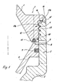
- Fig. 1 shows the connection region between the drum shell 1 and the drum base 2 of a separator drum 3 according to the invention with a vertical axis of rotation (not visible here).
- the drum shell 1 and the drum base 2 are each conical and go in the region of their largest diameter each in a on the outer circumference (drum shell) or on the outer circumference and inner circumference cylindrical portion 4, 5 via.
- the drum base 2 has an axially slightly longer cylindrical portion 5, in which a piston valve 6 is guided axially displaceably with a peripheral seal 7.
- the spool 6 is used to release Feststoffaustragsöffhungen 8 in the drum base 2 and to close.
- Fig. 1 shows the opened state of the solids discharge openings.
- the piston valve 6 In the closed state of the solids discharge openings 8 (not shown here) the piston valve 6 is located with an upper annular surface 9 on a lower collar 10 of the drum shell or on a ring seal 11 in the collar 10 at.
- the outer cylindrical and inner conical portion 4 of the drum shell 1 is dimensioned such that it engages in the cylindrical portion 5 of the drum base 2 axially.
- an external thread or internal thread 12,13 are respectively formed, so that the drum shell 1 is screwed into the drum base 2.
- This annular collar 14 has in the outermost region in turn at least one axially downwardly extending projection 15, which comprises an axially above the Verschraubungs Suitees projecting annular collar 16 on the drum base 2 outside.
- the projection 15 may also be formed as a circumferential annular collar or comprise a plurality of sections or areas which are arranged circumferentially distributed on the drum shell 1 (not visible here).
- Fig. 1 To Fig. 1 are the approach 15 and the annular collar 16 in their facing surfaces 17 a, b formed conically, which limits the penetration depth, while Fig. 2 In this area, axially extending cylindrical surfaces 18, 19 are formed.
- Fig. 2 discloses as such means a bore 20 in the drum shell 1.
- the tool eg a kind of handle, not shown here
- the bore may be closed by a bolt, for example, which is then released for attaching and securing the tool.
Landscapes
- Centrifugal Separators (AREA)
- Optical Couplings Of Light Guides (AREA)
- Sheets, Magazines, And Separation Thereof (AREA)
- Valve-Gear Or Valve Arrangements (AREA)
- Forms Removed On Construction Sites Or Auxiliary Members Thereof (AREA)
Description
- Die Erfindung betrifft eine Separatortrommel.
- Bei Separatoren mit vertikaler Drehachse erfolgt i.allg. entlang der Maschinenachse durch ein Zulaufrohr und diesem nachgeschaltete radiale Verteilerkanäle die Produktzufuhr in die Schleudertrommel, wo das Produkt in einen Tellerstapel aus i.allg. dicht zueinander angeordneten, relativ zueinander beabstandeten, konischen (Trenn-)Tellern eintritt. Am Trennteller lagern sich schwerere Feststoffe i.allg. an der Unterseite ab und wandern zum Außenumfang des Tellerpakts, wohingegen die Flüssigkeit nach innen hin fließt (Zwei-Phasen-Flüssig-Fest-Separation). Feststoffe werden oftmals über Düsen oder über Feststoffaustragsöffnungen mit vorgeschalteten Kolbenschieber ausgetragen.
- Die Trommel mit vertikaler Drehachse weist im allgemeinen ein Trommelunterteil und ein Trommeloberteil bzw. Deckelteil auf, die mittels eines separaten Verschlussringes miteinander verschraubt sind. Eine solche Konstruktion ist z.B. aus der
DE 35 11 422 oder derDE 39 36 165 A1 bekannt. Ein direktes Einsetzen des Trommelunterteils in das Trommeloberteil - siehe z.B. dieUS 2,369,222 oder dieEP 0 312 233 B1 kann zu undefinierten Laufzuständen führen, da sich die Trommelteile infolge der derzeit gebräuchlichen hohen Drehzahlen von bis zu 10000 U/min im Betrieb zu stark aufweiten, was wiederum zum Verlust einer exakten Führung der Teile zueinander führen kann. Dies gilt auch für die Idee einer direkten Verschraubung zwischen einem Trommelunterteil und einem Deckel. Konstruktionen dieser Art zeigen die Zentrifuge derEP 0309 478 B1 und der gattungsgemäße Separator derUS 1,356,274 . - Dennoch wäre eine funktionsfähige Direktverbindung zwischen dem Trommeloberteil (auch Trommeldeckel genannt) und dem Trommelunterteil, die ohne einen Zentrierring auskommt und auch bei höheren Drehzahlen voll funktionsfähig ist, von großem Interesse.
- Die Lösung des vorstehend genannten Problems ist die Aufgabe der Erfindung.
- Die Erfindung löst diese Aufgabe durch den Gegenstand des Anspruchs 1.
- Diese Konstruktion hat viele markante Vorteile.
- Der Verschlußring als separates Teil wird eingespart. Damit ist die Lösung kostengünstig.
- Durch die Gestaltung des Gewindebereiches wird das Eindringen von Schmutz sicher verhindert.
- Die Verklammerung wirkt der fliehkraftbedingten Aufweitung insbesondere des Trommelunterteils entgegen und sorgt für eine Zentrierung und Führung der tragenden Trommelteile zueinander.
- Vorteilhafte Ausgestaltungen sind den Unteransprüchen zu entnehmen.
- Ein das Trommelteil außen hintergreifender bzw. einklammernder Zentrierring ist aus der
PCT/SE/00249 - Vorzugsweise sind die im Bereich der Verklammerung aneinander liegenden Flächen des Trommeloberteils und des Trommelunterteils kegelig oder zylindrisch ausgebildet.
- Bei dieser Ausgestaltung können ohne weiteres bevorzugt Kolbenschieber und/oder andere Entleerungssysteme trotz der vereinfachten Verbindung zwischen Trommelunterteil und Trommeloberteil eingesetzt werden.
- Das Trommelunterteil lässt sich einfacher gestalten, da es keinen Auflagepunkt für den Trommeldeckel mehr benötigt. Bezogen auf den Außendurchmesser der Trommel lässt sich ferner der Außendurchmesser der Trommeldichtung vergrößern. Dies resultiert in einer besseren Ausnutzung des Trommelinnenraumes.
- Nachfolgend wird die Erfindung anhand von Ausführungsbeispielen unter Bezug auf die Zeichnung anhand von Ausführungsbeispielen näher beschrieben. Es zeigt:
- Fig.1
- eine Schnittansicht durch den Verbindungsbereich zwischen dem Ober- und dem Trommelunterteil einer ersten erfindungsgemäßen Separatortrommel; und
- Fig.2
- eine Schnittansicht durch den Verbindungsbereich zwischen dem Ober- und dem Trommelunterteil einer zweiten erfindungsgemäßen Separatortrommel.
-
Fig. 1 zeigt den Verbindungsbereich zwischen dem Trommeloberteil 1 und dem Trommelunterteil 2 einer erfindungsgemäßen Separatortrommel 3 mit einer vertikalen Drehachse (hier nicht zu erkennen). - Das Trommeloberteil 1 und das Trommelunterteil 2 sind jeweils konisch ausgebildet und gehen im Bereich ihres größten Durchmessers jeweils in einen am Außenumfang (Trommeloberteil) bzw. am Außenumfang und Innenumfang zylindrischen Abschnitt 4, 5 über.
- Insbesondere das Trommelunterteil 2 weist einen axial etwas längeren zylindrischen Abschnitt 5 auf, in dem ein Kolbenschieber 6 mit einer Umfangsdichtung 7 axial verschieblich geführt ist. Der Kolbenschieber 6 dient dazu, Feststoffaustragsöffhungen 8 im Trommelunterteil 2 freizugeben und zu verschließen.
-
Fig. 1 zeigt den geöffneten Zustand der Feststoffaustragsöffnungen 8. - Im geschlossenen Zustand der Feststoffaustragsöffnungen 8 (hier nicht dargestellt) liegt der Kolbenschieber 6 mit einer oberen Ringfläche 9 an einem unteren Bund 10 des Trommeloberteils bzw. an einer Ringdichtung 11 im Bund 10 an.
- Der außen zylindrische und innen konische Abschnitt 4 des Trommeloberteils 1 ist derart bemessen, dass er in den zylindrischen Abschnitt 5 des Trommelunterteils 2 axial eingreift.
- Am Außenumfang des zylindrischen Abschnitt 4 des Trommeloberteils 1 und am Innenumfang des zylindrischen Abschnitts 5 des Trommelunterteils 2 sind jeweils ein Außengewinde bzw. Innengewinde 12,13 ausgebildet, so dass das Trommeloberteil 1 im Trommelunterteil 2 verschraubt ist.
- Auf dem oberen Rand der zylindrischen Abschnittes 5 des Trommelunterteils 2 liegt am äußersten Umfang des Trommelunterteils 2 oberhalb des Verschraubungsbereiches ein radial nach außen vorstehender Ringbund 14 des Trommeloberteils 1 auf. Dieser Ringbund 14 weist im äußersten Bereich wiederum wenigstens einen sich axial nach unten erstreckenden Ansatz 15 auf, der einen oberhalb des Verschraubungsbereiches axial nach oben vorkragenden Ringbund 16 am Trommelunterteil 2 außen umfasst. Der Ansatz 15 kann ebenfalls als umlaufender Ringbund ausgebildet sein oder mehrere Abschnitte bzw. Bereiche umfassen, die umfangsverteilt am Trommeloberteil 1 angeordnet sind (hier nicht zu erkennen).
- In axialer Richtung wird nach
Fig. 1 durch die Anlage der beiden Teile im Konus 17a, 17b die Eindringtiefe begrenzt - Derart wird jeweils eine direkte, verschlussringfreie Verschraubung zwischen dem Trommelunterteil 2 und dem Trommeloberteil 1 realisiert und dabei dennoch auf gleichfalls einfache Weise wirksam verhindert, dass durch das Aufweiten des Trommelunterteils 2 während der Drehung im Betrieb im Bereich der Verschraubung Probleme auftreten.
- Wesentlich ist bei der Konstruktion der
Fig. 1 und2 jeweils, dass der Ansatz 15 - ob ringförmig oder abschnittsweise umfangsverteilt - das Trommelunterteil 2, vorzugsweise dessen oberen Ringbund 16, außen nach Art einer Verklammerung hintergreift. - Nach
Fig. 1 sind der Ansatz 15 und der Ringbund 16 in ihren zueinandergewandten Flächen 17a,b kegelig ausgebildet, was die Eindringtiefe begrenzt, während nachFig. 2 in diesem Bereich sich axial erstreckende zylindrische Flächen 18, 19 ausgebildet sind. - Beide Varianten haben ihre Vorteile, wobei die Kegelflächen 17a,b einen besonders dichten Hintergriff realisieren, da diese Kegelflächen beim Aufweiten aufeinander auflaufen.
- Üblicherweise werden das Trommelunterteil 2 und das Trommeloberteil 1 am Verschlussring miteinander verschraubt. Da dieser hier gerade eingespart wird und andererseits am Trommeloberteil eine genügende Fläche zum Ansetzen eines entsprechenden (hier nicht dargestellten) Verschraubungswerkzeuges vorhanden ist, ist es zweckmäßig, das Trommeloberteil 3 nach einer Weiterbildung direkt mit Mitteln zum Anbringen eines derartigen Werkzeuges zu versehen.
Fig. 2 offenbart als derartige Mittel eine Bohrung 20 im Trommeloberteil 1. In dieser Bohrung 20 und ggf. einer oder mehreren weiteren Bohrungen kann mittels korrespondierenden Bolzen das Werkzeug (z.B. eine Art Griff; hier nicht dargestellt) zum Verschrauben der beiden Trommelteile miteinander befestigt werden. Im Betrieb kann die Bohrung z.B. von einem Schraubbolzen verschlossen sein, die dann zum Ansetzen und Befestigen des Werkzeugs gelöst wird. -
- Trommeloberteil
- 1
- Trommelunterteil
- 2
- Separatortrommel
- 3
- Abschnitt
- 4, 5
- Kolbenschieber
- 6
- Umfangsdichtung
- 7
- Feststoffaustragsöffnungen
- 8
- Ringfläche
- 9
- Bund
- 10
- Ringdichtung
- 11
- Außengewinde bzw. Innengewinde
- 12,13
- Ringbund
- 14
- Ansatz
- 15
- Ringbund
- 16
- Flächen
- 17, 18, 19
- Bohrung
- 20
Claims (6)
- Separatortrommel (3) für einen Separator mit einer vertikalen Drehachse,a) mit einem Trommeloberteil(1) undb) einem Trommetunterteil (2),c) wobei eine Verschraubung bzw. ein Gewinde zwischen dem Trommeloberteil (1) und dem Trommelunterteil (2) ausgebildet ist,d) wobei das Trommeloberteil in das Trommelunterteil direkt verschlussringfrei eingeschraubt ist unde) wobei das im Bereich der Verschraubung innenliegende Trommelteil das außenliegende Trommelteil im Bereich einer Verklammerung außen einklammert bzw. hintergreift,f) wobei das Trommeloberteil außen und innen konisch ausgebildet ist und in seinem unteren Bereich in einen zumindest am Außenumfang zylindrischen Abschnitt (4) übergeht,g) wobei das Trommelunterteil außen und innen konisch ausgebildet ist und in seinem oberen Bereich in einen außen und innen zylindrischen Abschnitt (5) übergeht,h) wobei das Trommeloberteil (1) einen unteren Ansatz (15) aufweist, der einen oberen Ringbund (16) am Trommelunterteil (2) außen zur Ausbildung der Verklammerung hintergreift,i) wobei am Außenumfang des zylindrischen Abschnitts (4) des Trommeloberteils (1) ein Außengewinde (12) und am Innenumfang eines zylindrischen Abschnitts (5) des Trommelunterteils (2) ein Innengewinde (13) ausgebildet sind, so dass das Trommeloberteil in das Trommelunterteil eingeschraubt ist, wobei der Ansatz (15) und der Ringbund (16) oberhalb des Verschraubungsbereiches liegen.
- Separatortrommel nach Anspruch 1, dadurch gekennzeichnet, dass die im Bereich der Verklammerung aneinander liegenden Flächen des Trommeloberteils (1) und des Trommelunterteils (2) kegelig ausgebildet sind.
- Separatortrommel nach Anspruch 1, dadurch gekennzeichnet, dass die im Bereich der Verklammerung aneinander liegenden Flächen des Trommeloberteils (1) und des Trommelunterteils (2) zylindrisch ausgebildet sind.
- Separatortrommel nach einem der vorstehenden Ansprüche, dadurch gekennzeichnet, dass der Ansatz (15) und der Ringbund (16) im Bereich ihrer zueinander gewandten Flächen (16, 17; 18, 19) kegelig oder zylindrisch ausgebildet sind.
- Separatortrommel nach einem der vorstehenden Ansprüche, dadurch gekennzeichnet, dass das im zylindrischen Abschnitt (5) des Trommelunterteils (2) ein Kolbenschieber (6) axial verschieblich geführt ist, der dazu dient, Feststoffaustragsöffnungen (8) im Trommelunterteil (2) freizugeben und zu verschließen.
- Separatortrommel nach einem der vorstehenden Ansprüche, dadurch gekennzeichnet, dass am Trommeloberteil (1) Mittel zum Anbringen oder Ansetzen eines Werkzeuges zum Verschrauben des Trommeloberteils (1) mit dem Trommelunterteil (2) ausgebildet sind.
Priority Applications (1)
| Application Number | Priority Date | Filing Date | Title |
|---|---|---|---|
| PL06704291T PL1848540T5 (pl) | 2005-02-08 | 2006-01-31 | Bęben wirówki |
Applications Claiming Priority (2)
| Application Number | Priority Date | Filing Date | Title |
|---|---|---|---|
| DE102005005660A DE102005005660A1 (de) | 2005-02-08 | 2005-02-08 | Separatortrommel |
| PCT/EP2006/050558 WO2006084806A1 (de) | 2005-02-08 | 2006-01-31 | Separatortrommel |
Publications (3)
| Publication Number | Publication Date |
|---|---|
| EP1848540A1 EP1848540A1 (de) | 2007-10-31 |
| EP1848540B1 EP1848540B1 (de) | 2010-03-03 |
| EP1848540B2 true EP1848540B2 (de) | 2013-05-01 |
Family
ID=35976766
Family Applications (1)
| Application Number | Title | Priority Date | Filing Date |
|---|---|---|---|
| EP06704291.1A Active EP1848540B2 (de) | 2005-02-08 | 2006-01-31 | Separatortrommel |
Country Status (9)
| Country | Link |
|---|---|
| US (1) | US7749148B2 (de) |
| EP (1) | EP1848540B2 (de) |
| JP (1) | JP4782147B2 (de) |
| CN (1) | CN100566844C (de) |
| AT (1) | ATE459424T1 (de) |
| DE (2) | DE102005005660A1 (de) |
| ES (1) | ES2340870T5 (de) |
| PL (1) | PL1848540T5 (de) |
| WO (1) | WO2006084806A1 (de) |
Families Citing this family (6)
| Publication number | Priority date | Publication date | Assignee | Title |
|---|---|---|---|---|
| DE102005005660A1 (de) * | 2005-02-08 | 2006-08-10 | Westfalia Separator Ag | Separatortrommel |
| DE102008008120A1 (de) * | 2008-02-08 | 2009-08-20 | Gea Westfalia Separator Gmbh | Separatortrommel mit mehrteiligem Trommeldeckel |
| DE202016101272U1 (de) * | 2016-03-08 | 2017-06-09 | Gea Mechanical Equipment Gmbh | Separator |
| EP3257587B1 (de) * | 2016-06-14 | 2018-12-26 | Alfa Laval Corporate AB | Zentrifugalabscheider mit zerlegbaren trommeloberteil |
| CN108580062B (zh) * | 2018-04-23 | 2020-05-22 | 江苏大洋环保工程有限公司 | 一种离心分离转鼓机 |
| EP3685921A1 (de) | 2019-01-28 | 2020-07-29 | Alfa Laval Corporate AB | Zentrifugalabscheider |
Citations (8)
| Publication number | Priority date | Publication date | Assignee | Title |
|---|---|---|---|---|
| US565278A (en) † | 1896-08-04 | Peelsy l | ||
| US565279A (en) † | 1896-08-04 | Peeley l | ||
| GB320300A (en) † | 1929-01-26 | 1929-10-10 | Koefoed Hauberg Marstrand & Helweg As Titan | Centrifugal machines, especially for purification or separation of liquids |
| US3843045A (en) † | 1973-04-16 | 1974-10-22 | Beckman Instruments Inc | Centrifuge rotor |
| US3899128A (en) † | 1968-08-23 | 1975-08-12 | Int Equipment Co | Zonal centrifuge rotors |
| GB1535554A (en) † | 1975-02-01 | 1978-12-13 | Westfalia Separator Ag | Separating drum |
| US4191325A (en) † | 1977-08-12 | 1980-03-04 | Alfa-Laval Ab | Centrifuge with sludge outlets at rotor periphery |
| EP0182902B1 (de) † | 1984-06-14 | 1987-09-30 | Alfa-Laval Ab | Zentrifugal-trennungsvorrichtung |
Family Cites Families (19)
| Publication number | Priority date | Publication date | Assignee | Title |
|---|---|---|---|---|
| DE121449C (de) * | ||||
| US1356274A (en) | 1920-01-20 | 1920-10-19 | Laura M Edmonds | Carrying-receptacle for automobiles |
| US2369222A (en) | 1942-05-21 | 1945-02-13 | Artesian Well & Equipment Co I | Well scraping tool |
| GB1021306A (en) * | 1963-03-14 | 1966-03-02 | Beckman Instruments Inc | High strength rigid cylindrical member and method |
| US3708111A (en) * | 1969-12-19 | 1973-01-02 | P Sheeler | Apparatus and method for gradient zonal centrifugation |
| US3730422A (en) * | 1971-05-25 | 1973-05-01 | Atomic Energy Commission | Continuous flow centrifuge with means for reducing pressure drop |
| JPS4834040Y1 (de) * | 1972-09-01 | 1973-10-15 | ||
| SE405213B (sv) * | 1976-06-11 | 1978-11-27 | Alfa Laval Ab | Centrifugalseparator |
| DD223080B1 (de) | 1984-04-19 | 1987-02-18 | Kyffhaeuserhuette Maschf | Trommel fuer zentrifugalseparatoren |
| JPS6290753U (de) * | 1985-11-28 | 1987-06-10 | ||
| SE453572B (sv) | 1986-06-16 | 1988-02-15 | Kompositprodukter Sk Fm Ab | Gengforband for sammanhallning av tva komponenter vilka er inrettade for snabb rotation omkring gengforbandets centrumaxel |
| SE8703965D0 (sv) | 1987-10-13 | 1987-10-13 | Alfa Laval Separation Ab | Centrifugalseparator |
| CN87215661U (zh) * | 1987-11-13 | 1988-07-06 | 浙江省青田县污水处理设备厂 | 顺流式离心分音机 |
| JPH07114982B2 (ja) * | 1988-06-07 | 1995-12-13 | ヴェストファリア ゼパラトール アクチエンゲゼルシャフト | 遠心分離機 |
| DD287147A7 (de) * | 1988-11-28 | 1991-02-21 | Maschinenfabrik Kyffhaeuserhuette Artern Gmbh,De | Trommel fuer einen zentrifugalseparator |
| DE3910302C1 (en) | 1989-03-30 | 1990-06-13 | Westfalia Separator Ag, 4740 Oelde, De | Centrifuge |
| CN2511391Y (zh) * | 2001-11-29 | 2002-09-18 | 马鞍山市通达电工设备厂 | 高速卧螺固液分离机 |
| DE10311168B4 (de) * | 2003-03-12 | 2006-05-11 | Westfalia Separator Ag | Schleudertrommel für einen Separator |
| DE102005005660A1 (de) * | 2005-02-08 | 2006-08-10 | Westfalia Separator Ag | Separatortrommel |
-
2005
- 2005-02-08 DE DE102005005660A patent/DE102005005660A1/de not_active Withdrawn
-
2006
- 2006-01-31 CN CNB2006800043922A patent/CN100566844C/zh active Active
- 2006-01-31 WO PCT/EP2006/050558 patent/WO2006084806A1/de not_active Ceased
- 2006-01-31 EP EP06704291.1A patent/EP1848540B2/de active Active
- 2006-01-31 AT AT06704291T patent/ATE459424T1/de not_active IP Right Cessation
- 2006-01-31 US US11/883,557 patent/US7749148B2/en active Active
- 2006-01-31 PL PL06704291T patent/PL1848540T5/pl unknown
- 2006-01-31 DE DE502006006332T patent/DE502006006332D1/de active Active
- 2006-01-31 JP JP2007554536A patent/JP4782147B2/ja active Active
- 2006-01-31 ES ES06704291T patent/ES2340870T5/es active Active
Patent Citations (8)
| Publication number | Priority date | Publication date | Assignee | Title |
|---|---|---|---|---|
| US565278A (en) † | 1896-08-04 | Peelsy l | ||
| US565279A (en) † | 1896-08-04 | Peeley l | ||
| GB320300A (en) † | 1929-01-26 | 1929-10-10 | Koefoed Hauberg Marstrand & Helweg As Titan | Centrifugal machines, especially for purification or separation of liquids |
| US3899128A (en) † | 1968-08-23 | 1975-08-12 | Int Equipment Co | Zonal centrifuge rotors |
| US3843045A (en) † | 1973-04-16 | 1974-10-22 | Beckman Instruments Inc | Centrifuge rotor |
| GB1535554A (en) † | 1975-02-01 | 1978-12-13 | Westfalia Separator Ag | Separating drum |
| US4191325A (en) † | 1977-08-12 | 1980-03-04 | Alfa-Laval Ab | Centrifuge with sludge outlets at rotor periphery |
| EP0182902B1 (de) † | 1984-06-14 | 1987-09-30 | Alfa-Laval Ab | Zentrifugal-trennungsvorrichtung |
Also Published As
| Publication number | Publication date |
|---|---|
| CN100566844C (zh) | 2009-12-09 |
| PL1848540T5 (pl) | 2013-11-29 |
| WO2006084806A1 (de) | 2006-08-17 |
| JP2008529768A (ja) | 2008-08-07 |
| US20090054223A1 (en) | 2009-02-26 |
| DE502006006332D1 (de) | 2010-04-15 |
| US7749148B2 (en) | 2010-07-06 |
| ATE459424T1 (de) | 2010-03-15 |
| PL1848540T3 (pl) | 2010-07-30 |
| DE102005005660A1 (de) | 2006-08-10 |
| EP1848540B1 (de) | 2010-03-03 |
| ES2340870T5 (es) | 2013-09-20 |
| EP1848540A1 (de) | 2007-10-31 |
| ES2340870T3 (es) | 2010-06-10 |
| JP4782147B2 (ja) | 2011-09-28 |
| CN101115566A (zh) | 2008-01-30 |
Similar Documents
| Publication | Publication Date | Title |
|---|---|---|
| EP2310135B1 (de) | Zentrifuge mit einer mit einem trenntellerpaket versehenen trommel | |
| EP1651352B1 (de) | Separator mit einer schleudertrommel mit einem tellerpaket | |
| WO2014128063A2 (de) | Trenntellerpaket | |
| EP3426405B1 (de) | Separator | |
| EP2928613B1 (de) | Auslassdüse für eine zentrifugentrommel | |
| DE10220757B4 (de) | Zentrifuge, insbesondere Separator | |
| EP2872256A1 (de) | Vollmantel-schneckenzentrifuge mit überlaufwehr | |
| DE20010743U1 (de) | Zentrifuge mit doppeltem Zulauf | |
| WO2011004014A1 (de) | Separator mit vertikaler drehachse | |
| EP1848540B2 (de) | Separatortrommel | |
| EP1786565B2 (de) | Selbstentleerender separator mit tellerpaket | |
| EP3354346B1 (de) | Zentrifuge zur stofftrennung | |
| WO2021064025A1 (de) | Vollmantel-schneckenzentrifuge | |
| EP3448577B1 (de) | Auslassdüse für eine zentrifugentrommel, zentrifugentrommel und montagewerkzeug | |
| EP1998896B1 (de) | Vollmantel-schneckenzentrifuge mit abflussöffnungen zur teil- und restentleerung der trommel | |
| DE102006047478A1 (de) | Separatortrommel mit optimiertem Verteiler | |
| DE102008008120A1 (de) | Separatortrommel mit mehrteiligem Trommeldeckel | |
| EP4252912B1 (de) | Siebschneckenzentrifuge | |
| DE202005015693U1 (de) | Separatortrommel mit optimiertem Verteiler | |
| DE202008007499U1 (de) | Zentrifugentrommel mit einem Verteiler | |
| WO2025098870A1 (de) | Schleudertrommel einer zentrifuge und zentrifuge mit einer solchen schleudertrommel | |
| DE102012018241A1 (de) | Separator |
Legal Events
| Date | Code | Title | Description |
|---|---|---|---|
| PUAI | Public reference made under article 153(3) epc to a published international application that has entered the european phase |
Free format text: ORIGINAL CODE: 0009012 |
|
| 17P | Request for examination filed |
Effective date: 20070711 |
|
| AK | Designated contracting states |
Kind code of ref document: A1 Designated state(s): AT BE BG CH CY CZ DE DK EE ES FI FR GB GR HU IE IS IT LI LT LU LV MC NL PL PT RO SE SI SK TR |
|
| DAX | Request for extension of the european patent (deleted) | ||
| RAP1 | Party data changed (applicant data changed or rights of an application transferred) |
Owner name: WESTFALIA SEPARATOR GMBH |
|
| RAP1 | Party data changed (applicant data changed or rights of an application transferred) |
Owner name: GEA WESTFALIA SEPARATOR GMBH |
|
| GRAP | Despatch of communication of intention to grant a patent |
Free format text: ORIGINAL CODE: EPIDOSNIGR1 |
|
| GRAS | Grant fee paid |
Free format text: ORIGINAL CODE: EPIDOSNIGR3 |
|
| GRAA | (expected) grant |
Free format text: ORIGINAL CODE: 0009210 |
|
| AK | Designated contracting states |
Kind code of ref document: B1 Designated state(s): AT BE BG CH CY CZ DE DK EE ES FI FR GB GR HU IE IS IT LI LT LU LV MC NL PL PT RO SE SI SK TR |
|
| REG | Reference to a national code |
Ref country code: GB Ref legal event code: FG4D Free format text: NOT ENGLISH |
|
| REG | Reference to a national code |
Ref country code: CH Ref legal event code: EP |
|
| REG | Reference to a national code |
Ref country code: IE Ref legal event code: FG4D |
|
| REF | Corresponds to: |
Ref document number: 502006006332 Country of ref document: DE Date of ref document: 20100415 Kind code of ref document: P |
|
| REG | Reference to a national code |
Ref country code: NL Ref legal event code: T3 |
|
| REG | Reference to a national code |
Ref country code: ES Ref legal event code: FG2A Ref document number: 2340870 Country of ref document: ES Kind code of ref document: T3 |
|
| REG | Reference to a national code |
Ref country code: SE Ref legal event code: TRGR |
|
| PG25 | Lapsed in a contracting state [announced via postgrant information from national office to epo] |
Ref country code: LT Free format text: LAPSE BECAUSE OF FAILURE TO SUBMIT A TRANSLATION OF THE DESCRIPTION OR TO PAY THE FEE WITHIN THE PRESCRIBED TIME-LIMIT Effective date: 20100303 |
|
| REG | Reference to a national code |
Ref country code: PL Ref legal event code: T3 |
|
| LTIE | Lt: invalidation of european patent or patent extension |
Effective date: 20100303 |
|
| PG25 | Lapsed in a contracting state [announced via postgrant information from national office to epo] |
Ref country code: SI Free format text: LAPSE BECAUSE OF FAILURE TO SUBMIT A TRANSLATION OF THE DESCRIPTION OR TO PAY THE FEE WITHIN THE PRESCRIBED TIME-LIMIT Effective date: 20100303 Ref country code: LV Free format text: LAPSE BECAUSE OF FAILURE TO SUBMIT A TRANSLATION OF THE DESCRIPTION OR TO PAY THE FEE WITHIN THE PRESCRIBED TIME-LIMIT Effective date: 20100303 |
|
| REG | Reference to a national code |
Ref country code: IE Ref legal event code: FD4D |
|
| PG25 | Lapsed in a contracting state [announced via postgrant information from national office to epo] |
Ref country code: CY Free format text: LAPSE BECAUSE OF FAILURE TO SUBMIT A TRANSLATION OF THE DESCRIPTION OR TO PAY THE FEE WITHIN THE PRESCRIBED TIME-LIMIT Effective date: 20100303 Ref country code: EE Free format text: LAPSE BECAUSE OF FAILURE TO SUBMIT A TRANSLATION OF THE DESCRIPTION OR TO PAY THE FEE WITHIN THE PRESCRIBED TIME-LIMIT Effective date: 20100303 Ref country code: GR Free format text: LAPSE BECAUSE OF FAILURE TO SUBMIT A TRANSLATION OF THE DESCRIPTION OR TO PAY THE FEE WITHIN THE PRESCRIBED TIME-LIMIT Effective date: 20100604 Ref country code: IE Free format text: LAPSE BECAUSE OF FAILURE TO SUBMIT A TRANSLATION OF THE DESCRIPTION OR TO PAY THE FEE WITHIN THE PRESCRIBED TIME-LIMIT Effective date: 20100303 Ref country code: RO Free format text: LAPSE BECAUSE OF FAILURE TO SUBMIT A TRANSLATION OF THE DESCRIPTION OR TO PAY THE FEE WITHIN THE PRESCRIBED TIME-LIMIT Effective date: 20100303 |
|
| PG25 | Lapsed in a contracting state [announced via postgrant information from national office to epo] |
Ref country code: CZ Free format text: LAPSE BECAUSE OF FAILURE TO SUBMIT A TRANSLATION OF THE DESCRIPTION OR TO PAY THE FEE WITHIN THE PRESCRIBED TIME-LIMIT Effective date: 20100303 Ref country code: IS Free format text: LAPSE BECAUSE OF FAILURE TO SUBMIT A TRANSLATION OF THE DESCRIPTION OR TO PAY THE FEE WITHIN THE PRESCRIBED TIME-LIMIT Effective date: 20100703 Ref country code: BG Free format text: LAPSE BECAUSE OF FAILURE TO SUBMIT A TRANSLATION OF THE DESCRIPTION OR TO PAY THE FEE WITHIN THE PRESCRIBED TIME-LIMIT Effective date: 20100603 Ref country code: SK Free format text: LAPSE BECAUSE OF FAILURE TO SUBMIT A TRANSLATION OF THE DESCRIPTION OR TO PAY THE FEE WITHIN THE PRESCRIBED TIME-LIMIT Effective date: 20100303 |
|
| PLBI | Opposition filed |
Free format text: ORIGINAL CODE: 0009260 |
|
| PLAX | Notice of opposition and request to file observation + time limit sent |
Free format text: ORIGINAL CODE: EPIDOSNOBS2 |
|
| 26 | Opposition filed |
Opponent name: ALFA LAVAL CORPORATE AB Effective date: 20101201 |
|
| PG25 | Lapsed in a contracting state [announced via postgrant information from national office to epo] |
Ref country code: DK Free format text: LAPSE BECAUSE OF FAILURE TO SUBMIT A TRANSLATION OF THE DESCRIPTION OR TO PAY THE FEE WITHIN THE PRESCRIBED TIME-LIMIT Effective date: 20100303 Ref country code: PT Free format text: LAPSE BECAUSE OF FAILURE TO SUBMIT A TRANSLATION OF THE DESCRIPTION OR TO PAY THE FEE WITHIN THE PRESCRIBED TIME-LIMIT Effective date: 20100705 |
|
| PLAF | Information modified related to communication of a notice of opposition and request to file observations + time limit |
Free format text: ORIGINAL CODE: EPIDOSCOBS2 |
|
| PLBB | Reply of patent proprietor to notice(s) of opposition received |
Free format text: ORIGINAL CODE: EPIDOSNOBS3 |
|
| BERE | Be: lapsed |
Owner name: GEA WESTFALIA SEPARATOR G.M.B.H. Effective date: 20110131 |
|
| PG25 | Lapsed in a contracting state [announced via postgrant information from national office to epo] |
Ref country code: MC Free format text: LAPSE BECAUSE OF NON-PAYMENT OF DUE FEES Effective date: 20110131 |
|
| REG | Reference to a national code |
Ref country code: CH Ref legal event code: PL |
|
| GBPC | Gb: european patent ceased through non-payment of renewal fee |
Effective date: 20110131 |
|
| PG25 | Lapsed in a contracting state [announced via postgrant information from national office to epo] |
Ref country code: CH Free format text: LAPSE BECAUSE OF NON-PAYMENT OF DUE FEES Effective date: 20110131 Ref country code: LI Free format text: LAPSE BECAUSE OF NON-PAYMENT OF DUE FEES Effective date: 20110131 |
|
| PG25 | Lapsed in a contracting state [announced via postgrant information from national office to epo] |
Ref country code: GB Free format text: LAPSE BECAUSE OF NON-PAYMENT OF DUE FEES Effective date: 20110131 Ref country code: BE Free format text: LAPSE BECAUSE OF NON-PAYMENT OF DUE FEES Effective date: 20110131 |
|
| REG | Reference to a national code |
Ref country code: AT Ref legal event code: MM01 Ref document number: 459424 Country of ref document: AT Kind code of ref document: T Effective date: 20110131 |
|
| APAH | Appeal reference modified |
Free format text: ORIGINAL CODE: EPIDOSCREFNO |
|
| APBM | Appeal reference recorded |
Free format text: ORIGINAL CODE: EPIDOSNREFNO |
|
| APBP | Date of receipt of notice of appeal recorded |
Free format text: ORIGINAL CODE: EPIDOSNNOA2O |
|
| APBM | Appeal reference recorded |
Free format text: ORIGINAL CODE: EPIDOSNREFNO |
|
| APBP | Date of receipt of notice of appeal recorded |
Free format text: ORIGINAL CODE: EPIDOSNNOA2O |
|
| PG25 | Lapsed in a contracting state [announced via postgrant information from national office to epo] |
Ref country code: AT Free format text: LAPSE BECAUSE OF NON-PAYMENT OF DUE FEES Effective date: 20110131 |
|
| APBU | Appeal procedure closed |
Free format text: ORIGINAL CODE: EPIDOSNNOA9O |
|
| PUAH | Patent maintained in amended form |
Free format text: ORIGINAL CODE: 0009272 |
|
| STAA | Information on the status of an ep patent application or granted ep patent |
Free format text: STATUS: PATENT MAINTAINED AS AMENDED |
|
| 27A | Patent maintained in amended form |
Effective date: 20130501 |
|
| AK | Designated contracting states |
Kind code of ref document: B2 Designated state(s): AT BE BG CH CY CZ DE DK EE ES FI FR GB GR HU IE IS IT LI LT LU LV MC NL PL PT RO SE SI SK TR |
|
| PG25 | Lapsed in a contracting state [announced via postgrant information from national office to epo] |
Ref country code: LU Free format text: LAPSE BECAUSE OF NON-PAYMENT OF DUE FEES Effective date: 20110131 |
|
| REG | Reference to a national code |
Ref country code: DE Ref legal event code: R102 Ref document number: 502006006332 Country of ref document: DE Effective date: 20130501 |
|
| REG | Reference to a national code |
Ref country code: SE Ref legal event code: RPEO |
|
| REG | Reference to a national code |
Ref country code: NL Ref legal event code: T3 |
|
| REG | Reference to a national code |
Ref country code: ES Ref legal event code: DC2A Ref document number: 2340870 Country of ref document: ES Kind code of ref document: T5 Effective date: 20130920 |
|
| PG25 | Lapsed in a contracting state [announced via postgrant information from national office to epo] |
Ref country code: TR Free format text: LAPSE BECAUSE OF FAILURE TO SUBMIT A TRANSLATION OF THE DESCRIPTION OR TO PAY THE FEE WITHIN THE PRESCRIBED TIME-LIMIT Effective date: 20100303 |
|
| PG25 | Lapsed in a contracting state [announced via postgrant information from national office to epo] |
Ref country code: HU Free format text: LAPSE BECAUSE OF FAILURE TO SUBMIT A TRANSLATION OF THE DESCRIPTION OR TO PAY THE FEE WITHIN THE PRESCRIBED TIME-LIMIT Effective date: 20100303 |
|
| REG | Reference to a national code |
Ref country code: PL Ref legal event code: T5 |
|
| PG25 | Lapsed in a contracting state [announced via postgrant information from national office to epo] |
Ref country code: LV Free format text: LAPSE BECAUSE OF FAILURE TO SUBMIT A TRANSLATION OF THE DESCRIPTION OR TO PAY THE FEE WITHIN THE PRESCRIBED TIME-LIMIT Effective date: 20130501 |
|
| REG | Reference to a national code |
Ref country code: FR Ref legal event code: PLFP Year of fee payment: 11 |
|
| REG | Reference to a national code |
Ref country code: FR Ref legal event code: PLFP Year of fee payment: 12 |
|
| REG | Reference to a national code |
Ref country code: FR Ref legal event code: PLFP Year of fee payment: 13 |
|
| P01 | Opt-out of the competence of the unified patent court (upc) registered |
Effective date: 20230327 |
|
| PGFP | Annual fee paid to national office [announced via postgrant information from national office to epo] |
Ref country code: PL Payment date: 20241217 Year of fee payment: 20 |
|
| PGFP | Annual fee paid to national office [announced via postgrant information from national office to epo] |
Ref country code: NL Payment date: 20250124 Year of fee payment: 20 |
|
| PGFP | Annual fee paid to national office [announced via postgrant information from national office to epo] |
Ref country code: DE Payment date: 20250130 Year of fee payment: 20 |
|
| PGFP | Annual fee paid to national office [announced via postgrant information from national office to epo] |
Ref country code: FI Payment date: 20250123 Year of fee payment: 20 |
|
| PGFP | Annual fee paid to national office [announced via postgrant information from national office to epo] |
Ref country code: ES Payment date: 20250203 Year of fee payment: 20 |
|
| PGFP | Annual fee paid to national office [announced via postgrant information from national office to epo] |
Ref country code: SE Payment date: 20250123 Year of fee payment: 20 |
|
| PGFP | Annual fee paid to national office [announced via postgrant information from national office to epo] |
Ref country code: FR Payment date: 20250125 Year of fee payment: 20 |
|
| PGFP | Annual fee paid to national office [announced via postgrant information from national office to epo] |
Ref country code: IT Payment date: 20250129 Year of fee payment: 20 |