EP0309478B1 - A screw joint - Google Patents
A screw joint Download PDFInfo
- Publication number
- EP0309478B1 EP0309478B1 EP87904206A EP87904206A EP0309478B1 EP 0309478 B1 EP0309478 B1 EP 0309478B1 EP 87904206 A EP87904206 A EP 87904206A EP 87904206 A EP87904206 A EP 87904206A EP 0309478 B1 EP0309478 B1 EP 0309478B1
- Authority
- EP
- European Patent Office
- Prior art keywords
- screw
- screw joint
- component
- components
- load
- Prior art date
- Legal status (The legal status is an assumption and is not a legal conclusion. Google has not performed a legal analysis and makes no representation as to the accuracy of the status listed.)
- Expired - Lifetime
Links
Images
Classifications
-
- B—PERFORMING OPERATIONS; TRANSPORTING
- B04—CENTRIFUGAL APPARATUS OR MACHINES FOR CARRYING-OUT PHYSICAL OR CHEMICAL PROCESSES
- B04B—CENTRIFUGES
- B04B7/00—Elements of centrifuges
- B04B7/08—Rotary bowls
-
- B—PERFORMING OPERATIONS; TRANSPORTING
- B04—CENTRIFUGAL APPARATUS OR MACHINES FOR CARRYING-OUT PHYSICAL OR CHEMICAL PROCESSES
- B04B—CENTRIFUGES
- B04B7/00—Elements of centrifuges
- B04B7/02—Casings; Lids
- B04B2007/025—Lids for laboratory centrifuge rotors
Definitions
- the present invention relates to a screw joint of the kind intended for holding together two components which are intended to rotate rapidly about the centre axis of the screw joint, and the mutually co-acting screw threads of which components have a thread profile presenting flank surfaces inclined in relation to said centre axis, and which screw joint during rotation of said components are exposed to a deforming load due to at least one of a) the forces transferred by the screw joint and b) the centrifugal forces acting on said components.
- the major part of the force transmitted by the screw joint is normally concentrated on a few screw threads thereof, while other screw threads of the joint are only subjected to a relatively slight load.
- 50 % of the load lies on a first screw thread
- 25 % of the load lies on the next screw thread
- 12,5 % of the load lies on the next following screw thread
- the remaining screw threads are relatively free of load.
- US-A-3,250,463 discloses a self-opening centrifugal separator comprising a cover and a locking ring in engagement with the cover and secured to the rotor body by means of a screw joint.
- the upper portion of the locking ring is designed as a radially extending tool-grip without any axially extending part. This portion will not cause any bending deformation of the screw joint which can result in a more uniform distribution of the load between the various screw threads of the rapidly rotating screw joint. On the contrary it will make the upper portion of the locking ring stiffer in view of the extended radial dimension of said part.
- the main object of the present invention is to achieve more uniform distribution of the load between the various screw threads of a rapidly rotating screw joint of the aforesaid kind than has been possible hitherto.
- the solution afforded by the present invention is based on the understanding that the load acting on different screw threads of a screw joint can be equalized by varying the axial distance between mutually co-acting threads of the screw joint axially therealong, and that this variation in axial distance can be achieved by subjecting the components carrying said screw threads to varying degrees of relative deformation in a radial direction, with the aid of the forces to which the components are subjected as a result of their rapid rotation.
- At least one component of the screw joint includes a projecting part which is joined with said component at one end of the screw joint and protrudes from the component both in the radial and the axial direction so that said part will be so deformed, as a result of the rapid rotation of said component, as to rotate parts of said one component about axes which form right angles with axial sections through the centre axis of the screw joint and produce, over the axial extension of the screw joint, varying contributions to the radial deformation of said one component in a direction such as to obtain a pre-determined compensation for said deformation of the screw joint.
- the invention affords a highly beneficial solution to the aforesaid problem, since the rotational forces to which the screw joint is subjected are utilized to achieve the desired re-distribution of load on the screw threads of the joint. This obviates, inter alia, the need for conical screw threads, such screw threads presenting serious draw backs with respect to manufacture and to use.
- the aforesaid projecting part having axial extension forms an integral part of said one component and is suitably of tubular or anular configuration and incorporates a portion which extends essentially in a direction in which it defines an acute angle with the rotational axis of the screw joint.
- this angled part of said one component will strive to adopt a new position of equilibrium, therewith resulting in deformation of said component, such as to alter the radial distance between at least some of the mutually co-acting threads of the screw joint.
- the aforesaid part of said one component may also have the form of an internal sleeve whose one end is connected rigidly to a radially and inwardly projecting ballast element which defines an acute angle with said rotational axis and therewith generates a deforming torque when the screw joint is rotated rapidly.
- a more pronounced effect can be obtained in this context when the aforesaid part presents at least one portion which is less resistant to bending, i.e. more flexible, than the remainder of the component to which said part belongs, suitably by providing the portion with a circumferential groove.
- the invention can be applied with particular advantage to an ultracentrifuge, since the screw joint used to hold the lid of the centrifuge firmly in position on the rotor body is subjected to extremely large forces in the operating mode of the centrifuge. For instance, when the centrifuge is rotated at high speeds, the hydraulic pressure in the centrifuge rotor rises to values of such magnitude as to generate forces also in the axial direction of the centrifuge. In the case of large centrifuges, the axial load on the screw joint can reach several hundred tonnes. The screw joint thus quickly becomes a limiting factor with regard to the maximum speed at which the centrifuge rotor can be permitted to rotate.
- the aforesaid components may comprise a screw-threaded rotor body and a screw-threaded locking device the screw threads of which co-act with the screw threads of said rotor body in a manner to lock the rotor body together with a lid.
- the locking device suitably incorporates said part which when subjected to rotation at high speeds influences the deformation of the locking device.
- the locking device may have the form of a separate locking ring or may form part of the lid.
- the ultracentrifuge illustrated in Figure 2 includes a centrifuge body 3 having a lid 4, which is held in place by means of a screw-threaded locking ring 5, the screw threads of which are in screw engagement with an internal screw thread on the centrifuge body 3.
- the centrifuge body 3 is embraced by an external fibre bandage 6.
- this bandage is not a necessary feature of the invention, its presence does afford important advantages in connection with an optimisation of the screw joint, as explained below. It will be understood that the greater the flank angle of the screw threads, the easier it is to distribute the load over a plurality of screw threads. On the other hand, it will also be seen to be true that the greater the flank angle, the greater the forces that are transmitted radially between the inner and the outer parts of the screw joint.
- the upper part of the locking ring 5 of the Figure 2 embodiment merges with a deformation ring 7, which forms an acute angle with the rotational axis 8.
- Located at the upper extremity of the deformtation ring 7 is an upstanding flange 9, by means of which the locking ring 5 can be fitted to and removed from the centrifuge with the aid of a suitable friction tool.
- the reference 10 identifies a circumferential groove which facilitates deformation of the locking ring 5 and controls the location at which deformation takes place.
- Figure 3 is an enlarged sectional view of the screw joint, illustrating screw-thread engagement of the locking ring 5 with the centrifuge body 3 and also illustrating the state of the screw joint when the centrifuge is stationary and not subjected to load. It will be seen that in this case all of the screw threads are in essentially uniform engagement with one another.
- Figure 4 is a sectional view similar to that of Figure 3, but with the centrifuge in rotation, the lid 4 being therewith subjected to a force F as a result of this rotation and as a result of the mass located in the centrifuge. Torque will occur when the force F acts on the locking ring 5 at a given radial distance from the force-transferring screw joint.
- the screw joint illustrated in Figure 4 represents a pressure joint, wherewith the first screw threads will normally take up the heaviest load. Because ocf the torque generated by the force F, the last screw threads in the upper part of the screw joint illustrated in Figure 4 will also take-up a heavy load.
- the deformation ring 7 When the centrifuge is rotated at high speeds, the deformation ring 7 will strive to take a new position of equilibrium and, similar to the body 1 of the Figure 1 embodiment, will tend to rotate in the direction of the arrow A. It will be understood from the aforegoing that the reason for this tendency towards rotation is because parts of the deformation ring 7 located at a greater radial distance from the rotational axis are deformed to a greater extent than those parts which lie closer to said axis. Thus, there is generated a torque which deforms the locking ring 5 in a manner to increase the radial distance between the upper screw threads of the illustrated embodiment, therewith lightening the load thereon.
- the centrifuge body 3 of the ultracentrifuge illustrated in Figure 5 is provided with an external screw thread which co-acts with an external locking ring 11 intended for holding the lid 4 in its intended position.
- the locking ring 11 of the Figure 5 embodiment is provided with an external reinforcing fibre-bandage 12, in addition to the fibre bandage 6.
- this movement results in torque which causes radial deformation of the lower end of the locking ring 11, which in turn increases the radial distance between mutually co-acting screw threads at said end, whereas the depth of engagement of the intermediate screw threads increase.
- the force F from the lid generates torque which relieves the load on the upper screw threads to some extent.
- this embodiment will also afford equalization of the load on the various screw threads, by re-distributing the load from the outer screw threads to the intermediate screw threads.
- Figure 6 is a schematic sectional view of part of a centrifuge having an internal lid-locking ring 14, in accordance with Figure 2.
- the locking ring 14 is provided with an outwardly directed deformation ring 15, which tends to move in the direction of the arrow C such that the penetration depth between the upper screw threads increases, said screw threads thus taking-up a greater part of the load and therewith partially relieving the load on the remaining screw threads.
- a corresponding effect is also obtained with the embodiment illustrated in Figure 7 which incorporates an inwardly and downwardly directed deformation ring 16, as illustrated by means of the arrow D.
- the locking ring of the Figure 7 embodiment is more rigid in the radial direction than the locking ring of the Figure 6 embodiment, due to the fact that the homogenous ring has more material on a smaller radius.
- Figure 8 illustrates an embodiment in which the load on the uppermost screw threads of the illustrated screw joint is decreased as a result of movement of the deformation ring 17 in the direction E while increasing the load on the most central screw threads of the joint.
- the deformation ring 17 is mounted directly on the centrifuge body 3, which is connected to an inner locking ring 18 via the screw joint.
- Figure 9 illustrates a similar emodiment, although in this case the deformation ring 19 is directed outwardly and downwardly, which results in a tendency toward movement in the direction of the arrow M. This movement results in more of the load being transferred to the uppermost screw threads of the illustrated screw joint.
- the function of the aforedescribed embodiment is all based on the provision of a deformation ring which defines an acute angle with the axis of rotation, therewith to subject the screw joint to deforming torque.
- FIGS 10A and 10B show a partly sectional side view and a top-plan view respectively of an emgodiment of a combined locking and deformation ring 24.
- the upper end of the ring 24 is rigidly connected with radially and inwardly projecting ballast devices 25, which slope downwardly in a manner to form an acute angle with the axis of rotation.
- ballast devices 25 which slope downwardly in a manner to form an acute angle with the axis of rotation.
- the embodiment illustrated in Figure 11 incorporates an external locking ring 26 screwed onto the rotor body 3 of the centrifuge.
- both the screw-threaded part and a flange 28 projecting upwardly from the associated deformation ring 27 are each embraced by a reinforcing, composite ring 29 and 30 respectively.
- the deformation ring 27 will transfer load from the underlying screw threads to the uppermost screw threads of the illustrated screw joint. Futhermore, the deformation ring 27 causes a decrease in the stress concentrations at the transitions between the locking ring 26 and the deformation ring 27, which is highly beneficial.
- FIG 12 illustrates an ultracentrifuge with which a lid 31 is screwed directly onto the rotor body 3 of the centrifuge.
- the lid 31 of this embodiment is provided on its lower edge with a deformation ring 32 and a groove 33 which reduces the flexural rigidity of the ring.
- This screw joint is under tension and the deformation ring 32 is caused to move in the direction of the arrow L, therewith relieving the load on the heavily loaded lower screw threads of the joint and transferring a corresponding load to the most central screw threads. Since the lid of this embodiment extends radially in towards the axis of rotation 8, the lid is extremely rigid or inflexible and therefore requires no composite ring.
Landscapes
- Centrifugal Separators (AREA)
- Pressure Vessels And Lids Thereof (AREA)
Abstract
Description
- The present invention relates to a screw joint of the kind intended for holding together two components which are intended to rotate rapidly about the centre axis of the screw joint, and the mutually co-acting screw threads of which components have a thread profile presenting flank surfaces inclined in relation to said centre axis, and which screw joint during rotation of said components are exposed to a deforming load due to at least one of a) the forces transferred by the screw joint and b) the centrifugal forces acting on said components.
- As a result of varying axial deformation occurring in the screw-joint material when the joint is under tension, the major part of the force transmitted by the screw joint is normally concentrated on a few screw threads thereof, while other screw threads of the joint are only subjected to a relatively slight load. For example, in the case of a conventional nut and screw joint, 50 % of the load lies on a first screw thread, 25 % of the load lies on the next screw thread and 12,5 % of the load lies on the next following screw thread, whereas the remaining screw threads are relatively free of load. Since the distribution of load between the screw threads influences the dynamic strength of the screw joint, the aforementioned uneven load distribution on the screw threads causes the majority of fatique fractures to occur at the "first" load-bearing thread. Consequently, the useful life of a screw thread could be extended considerably, if it were possible to relieve the load on this "first" screw thread, this first screw thread normally taking 50 % of the total load.
- Attempts to achieve more uniform distribution of the load on the screw threads of a screw joint have been made in the past by designing the nut in a particular manner, such that the pressure-activated surface is located, for steering the force flow, so that the load is distributed as uniformly as possible over a plurality of screw threads.
- It is true of all types of screw joints which incorporate screw threads that have flank surfaces which slope in relation to the longitudinal axis that the axial contact between two mutually co-acting screw threads is influenced by the mutual radial position of the threads. Thus, the distribution of load between the screw threads of a screw joint can be influenced by changing the mutual radial position between the screw threads, as this will cause a change in the axial distance between mutually co-acting screw threads. Earlier attempts have been made to utilize this fact in a manner to obtain a uniform distribution of the load on a stationary screw joint, by providing one of the screw-threaded components of the screw joint with a conical screw thread along at least a part of its axial extension, c.f. for example GB-A-2 074 280. It is also possible by means of a suitable load to obtain a corresponding deformation of, e.g., a nut.
- US-A-3,250,463 discloses a self-opening centrifugal separator comprising a cover and a locking ring in engagement with the cover and secured to the rotor body by means of a screw joint. The upper portion of the locking ring is designed as a radially extending tool-grip without any axially extending part. This portion will not cause any bending deformation of the screw joint which can result in a more uniform distribution of the load between the various screw threads of the rapidly rotating screw joint. On the contrary it will make the upper portion of the locking ring stiffer in view of the extended radial dimension of said part.
- The main object of the present invention is to achieve more uniform distribution of the load between the various screw threads of a rapidly rotating screw joint of the aforesaid kind than has been possible hitherto.
- The solution afforded by the present invention is based on the understanding that the load acting on different screw threads of a screw joint can be equalized by varying the axial distance between mutually co-acting threads of the screw joint axially therealong, and that this variation in axial distance can be achieved by subjecting the components carrying said screw threads to varying degrees of relative deformation in a radial direction, with the aid of the forces to which the components are subjected as a result of their rapid rotation.
- It is a characteristic of a screw joint of the aforesaid kind constructed in accordance with the invention that at least one component of the screw joint includes a projecting part which is joined with said component at one end of the screw joint and protrudes from the component both in the radial and the axial direction so that said part will be so deformed, as a result of the rapid rotation of said component, as to rotate parts of said one component about axes which form right angles with axial sections through the centre axis of the screw joint and produce, over the axial extension of the screw joint, varying contributions to the radial deformation of said one component in a direction such as to obtain a pre-determined compensation for said deformation of the screw joint.
- The invention affords a highly beneficial solution to the aforesaid problem, since the rotational forces to which the screw joint is subjected are utilized to achieve the desired re-distribution of load on the screw threads of the joint. This obviates, inter alia, the need for conical screw threads, such screw threads presenting serious draw backs with respect to manufacture and to use.
- Preferably, the aforesaid projecting part having axial extension forms an integral part of said one component and is suitably of tubular or anular configuration and incorporates a portion which extends essentially in a direction in which it defines an acute angle with the rotational axis of the screw joint. As the screw joint is rapidly rotated, this angled part of said one component will strive to adopt a new position of equilibrium, therewith resulting in deformation of said component, such as to alter the radial distance between at least some of the mutually co-acting threads of the screw joint.
- The aforesaid part of said one component may also have the form of an internal sleeve whose one end is connected rigidly to a radially and inwardly projecting ballast element which defines an acute angle with said rotational axis and therewith generates a deforming torque when the screw joint is rotated rapidly.
- A more pronounced effect can be obtained in this context when the aforesaid part presents at least one portion which is less resistant to bending, i.e. more flexible, than the remainder of the component to which said part belongs, suitably by providing the portion with a circumferential groove.
- The invention can be applied with particular advantage to an ultracentrifuge, since the screw joint used to hold the lid of the centrifuge firmly in position on the rotor body is subjected to extremely large forces in the operating mode of the centrifuge. For instance, when the centrifuge is rotated at high speeds, the hydraulic pressure in the centrifuge rotor rises to values of such magnitude as to generate forces also in the axial direction of the centrifuge. In the case of large centrifuges, the axial load on the screw joint can reach several hundred tonnes. The screw joint thus quickly becomes a limiting factor with regard to the maximum speed at which the centrifuge rotor can be permitted to rotate.
- When practicing the concepts of the invention in conjunction with a centrifuge rotor, the aforesaid components may comprise a screw-threaded rotor body and a screw-threaded locking device the screw threads of which co-act with the screw threads of said rotor body in a manner to lock the rotor body together with a lid. In this case, the locking device suitably incorporates said part which when subjected to rotation at high speeds influences the deformation of the locking device.
- The locking device may have the form of a separate locking ring or may form part of the lid.
- The invention will now be described in more detail with reference to the accompanying drawings, in which
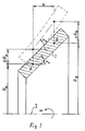
- Figure 1 illustrates the principles under which radial deformation occurs during rotation ;
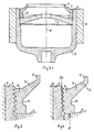
- Figure 2 is a schematic sectional view of an ultracentrifuge with the lid secured by means of an internal ring;
- Figure 3 illustrates on a larger scale the screw-thread engagement between the locking ring and the rotor body of the centrifuge according to Figure 2, with the centrifuge at rest;
- Figure 4 is a view corresponding to Figure 3 and shows the screw-thread engagement during rotation of the rotor body;
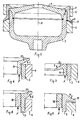
- Figure 5 is a schematic sectional view of an ultracentrifuge provided with an external locking ring;
- Figures 6-11 illustrate further embodiments of a screw joint constructed in accordance with the present invention and used in conjunction with a centrifuge;
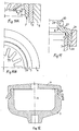
- Figure 12 is a sectional view of an ultracentrifuge equipped with a screw-threaded lid.
- Figure 1 illustrates the principles in accordance with which radial deformation will occur when a rotationally
symmetrical body 1 is rotated rapidly about an axis of rotation 2. The radial deformation ΔR which occurs when a rotationally symmetrical body of small radial extension, i.e. a thin-walled sleeve or annulus, is rotated at high speed can be expressed as - In the case of a rotating body (Figure 1) which forms an angle with the axis of rotation, the following expressions can be written when using the designations used in the Figure:
when ω = 0 tan α₀ =
when ω > 0 tan αω =
Since RB > RA and ΔR is proportional to R³, ΔRB > ΔRA, which in turn means that αω > α₀. This shows that the radially inner and radially outer parts of the body are deformed to mutually different extents, therewith generating torque. - As will be seen from the above equation relating to radial deformation, in addition to being obtained owing to mutually different rotational radii of different parts of the
body 1 such torque can also be obtained by changing the ratio of
- The equation is slightly different in the case of a body which has substantial radial extension. The manner in which the radius, density and Young's modulus influences the formation of the body, however, does not change.
- These facts can be utilized, in accordance with the invention, in conjunction with screw joints, e.g. in connection with ultracentrifuges, in a manner to obtain variable relative deformation of the two components of the screw joint, axially along the screw threads, and therewith obtain a more uniform distribution of the load over the various screw threads as stated in the introductory portion of the present sepcification.
The ultracentrifuge illustrated in Figure 2 includes acentrifuge body 3 having a lid 4, which is held in place by means of a screw-threaded locking ring 5, the screw threads of which are in screw engagement with an internal screw thread on thecentrifuge body 3. - In the illustrated embodiment of Figure 2, the
centrifuge body 3 is embraced by anexternal fibre bandage 6. Although this bandage is not a necessary feature of the invention, its presence does afford important advantages in connection with an optimisation of the screw joint, as explained below. It will be understood that the greater the flank angle of the screw threads, the easier it is to distribute the load over a plurality of screw threads. On the other hand, it will also be seen to be true that the greater the flank angle, the greater the forces that are transmitted radially between the inner and the outer parts of the screw joint. Since it is desirable that the two screw-joint components are, and remain, well centred in relation to one another, in the absence of pronounced radial clearance between said radially inner and radially outer component parts, it is necessary for the outer part of the screw joint to exhibit a much greater rigidity radially in rotation than the inner part of the screw joint. Furthermore, since the outer part of the screw joint is located at a greater median radius from the rotational axis than the inner part thereof, it is necessary for the ratio
fibre bandage 6. This applies to all embodiments of the various Figures in these drawings. - The upper part of the locking ring 5 of the Figure 2 embodiment merges with a deformation ring 7, which forms an acute angle with the
rotational axis 8. Located at the upper extremity of the deformtation ring 7 is an upstanding flange 9, by means of which the locking ring 5 can be fitted to and removed from the centrifuge with the aid of a suitable friction tool. Thereference 10 identifies a circumferential groove which facilitates deformation of the locking ring 5 and controls the location at which deformation takes place. - Figure 3 is an enlarged sectional view of the screw joint, illustrating screw-thread engagement of the locking ring 5 with the
centrifuge body 3 and also illustrating the state of the screw joint when the centrifuge is stationary and not subjected to load. It will be seen that in this case all of the screw threads are in essentially uniform engagement with one another. - Figure 4 is a sectional view similar to that of Figure 3, but with the centrifuge in rotation, the lid 4 being therewith subjected to a force F as a result of this rotation and as a result of the mass located in the centrifuge. Torque will occur when the force F acts on the locking ring 5 at a given radial distance from the force-transferring screw joint. The screw joint illustrated in Figure 4 represents a pressure joint, wherewith the first screw threads will normally take up the heaviest load. Because ocf the torque generated by the force F, the last screw threads in the upper part of the screw joint illustrated in Figure 4 will also take-up a heavy load.
- When the centrifuge is rotated at high speeds, the deformation ring 7 will strive to take a new position of equilibrium and, similar to the
body 1 of the Figure 1 embodiment, will tend to rotate in the direction of the arrow A. It will be understood from the aforegoing that the reason for this tendency towards rotation is because parts of the deformation ring 7 located at a greater radial distance from the rotational axis are deformed to a greater extent than those parts which lie closer to said axis. Thus, there is generated a torque which deforms the locking ring 5 in a manner to increase the radial distance between the upper screw threads of the illustrated embodiment, therewith lightening the load thereon. Consequently, because the torque resulting from the force F and movement of the deformation ring 7 in the direction of the arrow A, the centrally located screw threads of the screw joint will engage each other more firmly, whereas the screw engagement of the screw threads at the two extremities of the screw joint will slacken slightly. This means that the load on the outer screw threads will decrease and that the load on the intermediate screw threads will increase to a corresponding extent. - The
centrifuge body 3 of the ultracentrifuge illustrated in Figure 5 is provided with an external screw thread which co-acts with anexternal locking ring 11 intended for holding the lid 4 in its intended position. The lockingring 11 of the Figure 5 embodiment is provided with an external reinforcing fibre-bandage 12, in addition to thefibre bandage 6. When the centrifuge rotates, this screw joint is placed under tension which normally means that the outer screw threads at the two extremities of the screw joint will be subjected to the highest load. The load on the bottom screw threads of the illustrated screw joint, however, will decrease as a result of the tendency of thedeformation ring 13 to bend in the direction of the arrow B when the centrifuge is rotated at high speeds. This movement results in torque which causes radial deformation of the lower end of the lockingring 11, which in turn increases the radial distance between mutually co-acting screw threads at said end, whereas the depth of engagement of the intermediate screw threads increase. Correspondingly, the force F from the lid generates torque which relieves the load on the upper screw threads to some extent. Thus, this embodiment will also afford equalization of the load on the various screw threads, by re-distributing the load from the outer screw threads to the intermediate screw threads. - Figure 6 is a schematic sectional view of part of a centrifuge having an internal lid-locking
ring 14, in accordance with Figure 2. In this embodiment, however, the lockingring 14 is provided with an outwardly directeddeformation ring 15, which tends to move in the direction of the arrow C such that the penetration depth between the upper screw threads increases, said screw threads thus taking-up a greater part of the load and therewith partially relieving the load on the remaining screw threads. A corresponding effect is also obtained with the embodiment illustrated in Figure 7 which incorporates an inwardly and downwardly directed deformation ring 16, as illustrated by means of the arrow D. The locking ring of the Figure 7 embodiment, however, is more rigid in the radial direction than the locking ring of the Figure 6 embodiment, due to the fact that the homogenous ring has more material on a smaller radius. - As will be understood from the aforegoing, the distribution of load between the various screw threads of the screw joint depends, in all cases, essentially on the extent to which the axially directed force F acts on the screw joint and also on the flank angles of the screw threads. In this regard, Figure 8 illustrates an embodiment in which the load on the uppermost screw threads of the illustrated screw joint is decreased as a result of movement of the
deformation ring 17 in the direction E while increasing the load on the most central screw threads of the joint. In this embodiment, thedeformation ring 17 is mounted directly on thecentrifuge body 3, which is connected to aninner locking ring 18 via the screw joint. - Figure 9 illustrates a similar emodiment, although in this case the
deformation ring 19 is directed outwardly and downwardly, which results in a tendency toward movement in the direction of the arrow M. This movement results in more of the load being transferred to the uppermost screw threads of the illustrated screw joint. - The function of the aforedescribed embodiment is all based on the provision of a deformation ring which defines an acute angle with the axis of rotation, therewith to subject the screw joint to deforming torque.
- Figures 10A and 10B show a partly sectional side view and a top-plan view respectively of an emgodiment of a combined locking and deformation ring 24. The upper end of the ring 24 is rigidly connected with radially and inwardly projecting
ballast devices 25, which slope downwardly in a manner to form an acute angle with the axis of rotation. As a result of centrifugal forces these devices tend to move in the direction of the arrow I and therewith distribute part of the load from the upper screw threads of the illustrated screw joint to the most central screw threads thereof. - The embodiment illustrated in Figure 11 incorporates an
external locking ring 26 screwed onto therotor body 3 of the centrifuge. In this embodiment both the screw-threaded part and aflange 28 projecting upwardly from the associateddeformation ring 27 are each embraced by a reinforcing,composite ring deformation ring 27 will transfer load from the underlying screw threads to the uppermost screw threads of the illustrated screw joint. Futhermore, thedeformation ring 27 causes a decrease in the stress concentrations at the transitions between the lockingring 26 and thedeformation ring 27, which is highly beneficial. - Figure 12 illustrates an ultracentrifuge with which a
lid 31 is screwed directly onto therotor body 3 of the centrifuge. Thelid 31 of this embodiment is provided on its lower edge with adeformation ring 32 and agroove 33 which reduces the flexural rigidity of the ring. This screw joint is under tension and thedeformation ring 32 is caused to move in the direction of the arrow L, therewith relieving the load on the heavily loaded lower screw threads of the joint and transferring a corresponding load to the most central screw threads. Since the lid of this embodiment extends radially in towards the axis ofrotation 8, the lid is extremely rigid or inflexible and therefore requires no composite ring. - A number of solutions to the problem of equalizing the load on the screw threads of a screw joint have been presented in the aforegoing. It will be understood, however, by those skilled in this art that further variants are conceivable and that selective combinations of the illustrated embodiments can be employed. Furthermore, although all of the illustrated and described screw joints have been used in conjunction with ultracentrifuges, it will be understood that corresponding techniques can be applied in all cases where a screw joint is used in conjunction with rapidly rotating objects. The design of the deformation rings used can also be varied as desired and said rings may also be manufactured as separate elements and connected rigidly with the desired component of the screw joint. In the case of special applications, both components of the screw joint may each be provided with an individual deformation ring.
ρ = the density of the material
E = Young's modulus
R = radius
ω = angular velocity.
Claims (9)
Applications Claiming Priority (2)
| Application Number | Priority Date | Filing Date | Title |
|---|---|---|---|
| SE8602676 | 1986-06-16 | ||
| SE8602676A SE453572B (en) | 1986-06-16 | 1986-06-16 | GENG CONNECTIONS FOR JOINING TWO COMPONENTS WHICH ARE FITTED FOR QUICK ROTATION AROUND THE GENG CONNECTION CENTER |
Publications (2)
| Publication Number | Publication Date |
|---|---|
| EP0309478A1 EP0309478A1 (en) | 1989-04-05 |
| EP0309478B1 true EP0309478B1 (en) | 1992-04-08 |
Family
ID=20364829
Family Applications (1)
| Application Number | Title | Priority Date | Filing Date |
|---|---|---|---|
| EP87904206A Expired - Lifetime EP0309478B1 (en) | 1986-06-16 | 1987-06-11 | A screw joint |
Country Status (8)
| Country | Link |
|---|---|
| US (1) | US5000730A (en) |
| EP (1) | EP0309478B1 (en) |
| JP (1) | JPH01502963A (en) |
| CN (1) | CN87104299A (en) |
| DE (1) | DE3778161D1 (en) |
| ES (1) | ES2004424A6 (en) |
| SE (1) | SE453572B (en) |
| WO (1) | WO1987007533A1 (en) |
Cited By (3)
| Publication number | Priority date | Publication date | Assignee | Title |
|---|---|---|---|---|
| DE102008008120A1 (en) | 2008-02-08 | 2009-08-20 | Gea Westfalia Separator Gmbh | Separator drum with multi-part drum lid |
| US7749148B2 (en) | 2005-02-08 | 2010-07-06 | Westfalia Separator Ag | Separator drum having a screw connection |
| EP3685921A1 (en) | 2019-01-28 | 2020-07-29 | Alfa Laval Corporate AB | Centrifugal separator |
Families Citing this family (5)
| Publication number | Priority date | Publication date | Assignee | Title |
|---|---|---|---|---|
| GB2315310B (en) * | 1997-05-14 | 1999-06-23 | Yuen | Connecting means |
| US7611451B2 (en) | 2005-01-11 | 2009-11-03 | Cummins Filtration Ip Inc. | Centrifuge assembly with open-ended canister and closure caps |
| JP6410502B2 (en) * | 2014-07-16 | 2018-10-24 | 日立オートモティブシステムズ株式会社 | Shock absorber |
| CN106151515A (en) * | 2016-06-27 | 2016-11-23 | 无锡迪奥机械有限公司 | A kind of end socket of threaded lock seaming circle |
| CN105972208A (en) * | 2016-07-01 | 2016-09-28 | 无锡欧洛普科技有限公司 | Thread telescopic shell cover |
Family Cites Families (15)
| Publication number | Priority date | Publication date | Assignee | Title |
|---|---|---|---|---|
| US607109A (en) * | 1898-07-12 | Process of and apparatus for clarifying milk | ||
| US1032641A (en) * | 1911-09-23 | 1912-07-16 | Laval Separator Co De | Centrifugal clarifier and filter. |
| GB429574A (en) * | 1934-02-26 | 1935-05-31 | Koefoed Hauberg Marstrand & Helweg As Titan | Improvements in or relating to centrifugal separators |
| US3012710A (en) * | 1957-10-30 | 1961-12-12 | Westfalia Separator Ag | Centrifugal separator having lining of elastomer material |
| US3239136A (en) * | 1962-05-07 | 1966-03-08 | George N Hein | Centrifuge and centrifuge head for separating constituents of a liquid and a liner therefor |
| NL260435A (en) * | 1960-03-14 | |||
| DK117208B (en) * | 1962-01-31 | 1970-03-23 | Separator Ab | Process for centrifugation using a separation sludge centrifuge centrifuge and a separation centrifuge for carrying out the process. |
| NL128842C (en) * | 1964-05-02 | |||
| US3539096A (en) * | 1967-04-27 | 1970-11-10 | Dow Oliver Inc | Hy-g centrifuge |
| FR96448E (en) * | 1968-01-09 | 1972-06-30 | Alfa Laval Ab | Centrifuge. |
| US3899128A (en) * | 1968-08-23 | 1975-08-12 | Int Equipment Co | Zonal centrifuge rotors |
| SE324337B (en) * | 1968-10-14 | 1970-05-25 | Alfa Laval Ab | |
| US4059223A (en) * | 1976-08-16 | 1977-11-22 | Dorr-Oliver Incorporated | Centrifuge pressure relief device |
| US4177921A (en) * | 1977-09-29 | 1979-12-11 | Beckman Instruments, Inc. | One piece chylomicron rotor liner |
| US4342419A (en) * | 1980-10-31 | 1982-08-03 | Beckman Instruments, Inc. | Safety cover for centrifuge bucket |
-
1986
- 1986-06-16 SE SE8602676A patent/SE453572B/en not_active IP Right Cessation
-
1987
- 1987-06-11 WO PCT/SE1987/000276 patent/WO1987007533A1/en not_active Ceased
- 1987-06-11 EP EP87904206A patent/EP0309478B1/en not_active Expired - Lifetime
- 1987-06-11 JP JP62503732A patent/JPH01502963A/en active Pending
- 1987-06-11 DE DE8787904206T patent/DE3778161D1/en not_active Expired - Fee Related
- 1987-06-11 US US07/278,507 patent/US5000730A/en not_active Expired - Fee Related
- 1987-06-15 ES ES8701758A patent/ES2004424A6/en not_active Expired
- 1987-06-16 CN CN198787104299A patent/CN87104299A/en active Pending
Cited By (6)
| Publication number | Priority date | Publication date | Assignee | Title |
|---|---|---|---|---|
| US7749148B2 (en) | 2005-02-08 | 2010-07-06 | Westfalia Separator Ag | Separator drum having a screw connection |
| DE102008008120A1 (en) | 2008-02-08 | 2009-08-20 | Gea Westfalia Separator Gmbh | Separator drum with multi-part drum lid |
| EP3685921A1 (en) | 2019-01-28 | 2020-07-29 | Alfa Laval Corporate AB | Centrifugal separator |
| WO2020156739A1 (en) | 2019-01-28 | 2020-08-06 | Alfa Laval Corporate Ab | Centrifugal separator |
| US20220072565A1 (en) * | 2019-01-28 | 2022-03-10 | Alfa Laval Corporate Ab | Centrifugal separator |
| US12275021B2 (en) * | 2019-01-28 | 2025-04-15 | Alfa Laval Corporate Ab | Centrifugal separator having a screw connection between upper and lower bowls |
Also Published As
| Publication number | Publication date |
|---|---|
| CN87104299A (en) | 1987-12-23 |
| JPH01502963A (en) | 1989-10-12 |
| WO1987007533A1 (en) | 1987-12-17 |
| ES2004424A6 (en) | 1989-01-01 |
| SE453572B (en) | 1988-02-15 |
| SE8602676D0 (en) | 1986-06-16 |
| DE3778161D1 (en) | 1992-05-14 |
| EP0309478A1 (en) | 1989-04-05 |
| US5000730A (en) | 1991-03-19 |
| SE8602676L (en) | 1987-12-17 |
Similar Documents
| Publication | Publication Date | Title |
|---|---|---|
| EP0309478B1 (en) | A screw joint | |
| CN1062225C (en) | Ducted anti-torque rotor with floating blades | |
| EP0224927B1 (en) | Flexible composite ultracentrifuge rotor | |
| US5009539A (en) | Clamping set with screw sleeve | |
| US5167582A (en) | Torque transmitting flexible coupling with helical spring element | |
| JP2007261574A (en) | Bicycle pedal crank assembly and related member | |
| AU570392B2 (en) | Centrifuge rotor and method of assembly | |
| US4583960A (en) | Heavy duty yoke | |
| GB2120751A (en) | Yokes for universal joints | |
| EP0642635B1 (en) | A fly wheel arrangement | |
| JPS62118115A (en) | Supporter for roller bearing | |
| EP0270579A1 (en) | Decanter centrifuge. | |
| US4784372A (en) | Traction sheave | |
| SE523196C2 (en) | Device and method of drive shaft | |
| EP0182902B1 (en) | Centrifugal separator | |
| JPH0317950Y2 (en) | ||
| JP2980676B2 (en) | Centrifugal decanter | |
| US4107950A (en) | Flexible-disk coupling | |
| GB2091136A (en) | Separator | |
| JPS62113919A (en) | Power transmisison shaft | |
| US4579510A (en) | Axial flow fan impeller | |
| WO1994006710A1 (en) | Improvements in or relating to winches | |
| SU1484902A1 (en) | Joint of drill pipe with lock of unsimilar materials | |
| EP3917677B1 (en) | Centrifugal separator | |
| JPH045505B2 (en) |
Legal Events
| Date | Code | Title | Description |
|---|---|---|---|
| PUAI | Public reference made under article 153(3) epc to a published international application that has entered the european phase |
Free format text: ORIGINAL CODE: 0009012 |
|
| 17P | Request for examination filed |
Effective date: 19881115 |
|
| AK | Designated contracting states |
Kind code of ref document: A1 Designated state(s): AT BE CH DE FR GB IT LI LU NL SE |
|
| RBV | Designated contracting states (corrected) |
Designated state(s): DE FR GB IT |
|
| RBV | Designated contracting states (corrected) |
Designated state(s): DE FR GB IT SE |
|
| 17Q | First examination report despatched |
Effective date: 19900221 |
|
| GRAA | (expected) grant |
Free format text: ORIGINAL CODE: 0009210 |
|
| AK | Designated contracting states |
Kind code of ref document: B1 Designated state(s): DE FR GB IT SE |
|
| ITF | It: translation for a ep patent filed | ||
| REF | Corresponds to: |
Ref document number: 3778161 Country of ref document: DE Date of ref document: 19920514 |
|
| ET | Fr: translation filed | ||
| PLBE | No opposition filed within time limit |
Free format text: ORIGINAL CODE: 0009261 |
|
| STAA | Information on the status of an ep patent application or granted ep patent |
Free format text: STATUS: NO OPPOSITION FILED WITHIN TIME LIMIT |
|
| 26N | No opposition filed | ||
| EAL | Se: european patent in force in sweden |
Ref document number: 87904206.7 |
|
| PGFP | Annual fee paid to national office [announced via postgrant information from national office to epo] |
Ref country code: GB Payment date: 19980522 Year of fee payment: 12 |
|
| PGFP | Annual fee paid to national office [announced via postgrant information from national office to epo] |
Ref country code: FR Payment date: 19980617 Year of fee payment: 12 |
|
| PG25 | Lapsed in a contracting state [announced via postgrant information from national office to epo] |
Ref country code: GB Free format text: LAPSE BECAUSE OF NON-PAYMENT OF DUE FEES Effective date: 19990611 |
|
| PG25 | Lapsed in a contracting state [announced via postgrant information from national office to epo] |
Ref country code: FR Free format text: THE PATENT HAS BEEN ANNULLED BY A DECISION OF A NATIONAL AUTHORITY Effective date: 19990630 |
|
| GBPC | Gb: european patent ceased through non-payment of renewal fee |
Effective date: 19990611 |
|
| PGFP | Annual fee paid to national office [announced via postgrant information from national office to epo] |
Ref country code: SE Payment date: 20000417 Year of fee payment: 14 |
|
| PGFP | Annual fee paid to national office [announced via postgrant information from national office to epo] |
Ref country code: DE Payment date: 20000620 Year of fee payment: 14 |
|
| REG | Reference to a national code |
Ref country code: FR Ref legal event code: ST |
|
| PG25 | Lapsed in a contracting state [announced via postgrant information from national office to epo] |
Ref country code: SE Free format text: LAPSE BECAUSE OF NON-PAYMENT OF DUE FEES Effective date: 20010612 |
|
| EUG | Se: european patent has lapsed |
Ref document number: 87904206.7 |
|
| PG25 | Lapsed in a contracting state [announced via postgrant information from national office to epo] |
Ref country code: DE Free format text: LAPSE BECAUSE OF NON-PAYMENT OF DUE FEES Effective date: 20020403 |
|
| PG25 | Lapsed in a contracting state [announced via postgrant information from national office to epo] |
Ref country code: IT Free format text: LAPSE BECAUSE OF NON-PAYMENT OF DUE FEES;WARNING: LAPSES OF ITALIAN PATENTS WITH EFFECTIVE DATE BEFORE 2007 MAY HAVE OCCURRED AT ANY TIME BEFORE 2007. THE CORRECT EFFECTIVE DATE MAY BE DIFFERENT FROM THE ONE RECORDED. Effective date: 20050611 |