EP1839986A1 - Contrôle de mode de conduite - Google Patents
Contrôle de mode de conduite Download PDFInfo
- Publication number
- EP1839986A1 EP1839986A1 EP07104966A EP07104966A EP1839986A1 EP 1839986 A1 EP1839986 A1 EP 1839986A1 EP 07104966 A EP07104966 A EP 07104966A EP 07104966 A EP07104966 A EP 07104966A EP 1839986 A1 EP1839986 A1 EP 1839986A1
- Authority
- EP
- European Patent Office
- Prior art keywords
- engine
- intention
- torque
- clutch
- accelerate
- Prior art date
- Legal status (The legal status is an assumption and is not a legal conclusion. Google has not performed a legal analysis and makes no representation as to the accuracy of the status listed.)
- Withdrawn
Links
Images


Classifications
-
- B—PERFORMING OPERATIONS; TRANSPORTING
- B60—VEHICLES IN GENERAL
- B60K—ARRANGEMENT OR MOUNTING OF PROPULSION UNITS OR OF TRANSMISSIONS IN VEHICLES; ARRANGEMENT OR MOUNTING OF PLURAL DIVERSE PRIME-MOVERS IN VEHICLES; AUXILIARY DRIVES FOR VEHICLES; INSTRUMENTATION OR DASHBOARDS FOR VEHICLES; ARRANGEMENTS IN CONNECTION WITH COOLING, AIR INTAKE, GAS EXHAUST OR FUEL SUPPLY OF PROPULSION UNITS IN VEHICLES
- B60K6/00—Arrangement or mounting of plural diverse prime-movers for mutual or common propulsion, e.g. hybrid propulsion systems comprising electric motors and internal combustion engines ; Control systems therefor, i.e. systems controlling two or more prime movers, or controlling one of these prime movers and any of the transmission, drive or drive units Informative references: mechanical gearings with secondary electric drive F16H3/72; arrangements for handling mechanical energy structurally associated with the dynamo-electric machine H02K7/00; machines comprising structurally interrelated motor and generator parts H02K51/00; dynamo-electric machines not otherwise provided for in H02K see H02K99/00
- B60K6/20—Arrangement or mounting of plural diverse prime-movers for mutual or common propulsion, e.g. hybrid propulsion systems comprising electric motors and internal combustion engines ; Control systems therefor, i.e. systems controlling two or more prime movers, or controlling one of these prime movers and any of the transmission, drive or drive units Informative references: mechanical gearings with secondary electric drive F16H3/72; arrangements for handling mechanical energy structurally associated with the dynamo-electric machine H02K7/00; machines comprising structurally interrelated motor and generator parts H02K51/00; dynamo-electric machines not otherwise provided for in H02K see H02K99/00 the prime-movers consisting of electric motors and internal combustion engines, e.g. HEVs
- B60K6/22—Arrangement or mounting of plural diverse prime-movers for mutual or common propulsion, e.g. hybrid propulsion systems comprising electric motors and internal combustion engines ; Control systems therefor, i.e. systems controlling two or more prime movers, or controlling one of these prime movers and any of the transmission, drive or drive units Informative references: mechanical gearings with secondary electric drive F16H3/72; arrangements for handling mechanical energy structurally associated with the dynamo-electric machine H02K7/00; machines comprising structurally interrelated motor and generator parts H02K51/00; dynamo-electric machines not otherwise provided for in H02K see H02K99/00 the prime-movers consisting of electric motors and internal combustion engines, e.g. HEVs characterised by apparatus, components or means specially adapted for HEVs
- B60K6/38—Arrangement or mounting of plural diverse prime-movers for mutual or common propulsion, e.g. hybrid propulsion systems comprising electric motors and internal combustion engines ; Control systems therefor, i.e. systems controlling two or more prime movers, or controlling one of these prime movers and any of the transmission, drive or drive units Informative references: mechanical gearings with secondary electric drive F16H3/72; arrangements for handling mechanical energy structurally associated with the dynamo-electric machine H02K7/00; machines comprising structurally interrelated motor and generator parts H02K51/00; dynamo-electric machines not otherwise provided for in H02K see H02K99/00 the prime-movers consisting of electric motors and internal combustion engines, e.g. HEVs characterised by apparatus, components or means specially adapted for HEVs characterised by the driveline clutches
- B60K6/387—Actuated clutches, i.e. clutches engaged or disengaged by electric, hydraulic or mechanical actuating means
-
- B—PERFORMING OPERATIONS; TRANSPORTING
- B60—VEHICLES IN GENERAL
- B60W—CONJOINT CONTROL OF VEHICLE SUB-UNITS OF DIFFERENT TYPE OR DIFFERENT FUNCTION; CONTROL SYSTEMS SPECIALLY ADAPTED FOR HYBRID VEHICLES; ROAD VEHICLE DRIVE CONTROL SYSTEMS FOR PURPOSES NOT RELATED TO THE CONTROL OF A PARTICULAR SUB-UNIT
- B60W20/00—Control systems specially adapted for hybrid vehicles
- B60W20/20—Control strategies involving selection of hybrid configuration, e.g. selection between series or parallel configuration
-
- B—PERFORMING OPERATIONS; TRANSPORTING
- B60—VEHICLES IN GENERAL
- B60K—ARRANGEMENT OR MOUNTING OF PROPULSION UNITS OR OF TRANSMISSIONS IN VEHICLES; ARRANGEMENT OR MOUNTING OF PLURAL DIVERSE PRIME-MOVERS IN VEHICLES; AUXILIARY DRIVES FOR VEHICLES; INSTRUMENTATION OR DASHBOARDS FOR VEHICLES; ARRANGEMENTS IN CONNECTION WITH COOLING, AIR INTAKE, GAS EXHAUST OR FUEL SUPPLY OF PROPULSION UNITS IN VEHICLES
- B60K6/00—Arrangement or mounting of plural diverse prime-movers for mutual or common propulsion, e.g. hybrid propulsion systems comprising electric motors and internal combustion engines ; Control systems therefor, i.e. systems controlling two or more prime movers, or controlling one of these prime movers and any of the transmission, drive or drive units Informative references: mechanical gearings with secondary electric drive F16H3/72; arrangements for handling mechanical energy structurally associated with the dynamo-electric machine H02K7/00; machines comprising structurally interrelated motor and generator parts H02K51/00; dynamo-electric machines not otherwise provided for in H02K see H02K99/00
- B60K6/20—Arrangement or mounting of plural diverse prime-movers for mutual or common propulsion, e.g. hybrid propulsion systems comprising electric motors and internal combustion engines ; Control systems therefor, i.e. systems controlling two or more prime movers, or controlling one of these prime movers and any of the transmission, drive or drive units Informative references: mechanical gearings with secondary electric drive F16H3/72; arrangements for handling mechanical energy structurally associated with the dynamo-electric machine H02K7/00; machines comprising structurally interrelated motor and generator parts H02K51/00; dynamo-electric machines not otherwise provided for in H02K see H02K99/00 the prime-movers consisting of electric motors and internal combustion engines, e.g. HEVs
- B60K6/42—Arrangement or mounting of plural diverse prime-movers for mutual or common propulsion, e.g. hybrid propulsion systems comprising electric motors and internal combustion engines ; Control systems therefor, i.e. systems controlling two or more prime movers, or controlling one of these prime movers and any of the transmission, drive or drive units Informative references: mechanical gearings with secondary electric drive F16H3/72; arrangements for handling mechanical energy structurally associated with the dynamo-electric machine H02K7/00; machines comprising structurally interrelated motor and generator parts H02K51/00; dynamo-electric machines not otherwise provided for in H02K see H02K99/00 the prime-movers consisting of electric motors and internal combustion engines, e.g. HEVs characterised by the architecture of the hybrid electric vehicle
- B60K6/48—Parallel type
-
- B—PERFORMING OPERATIONS; TRANSPORTING
- B60—VEHICLES IN GENERAL
- B60K—ARRANGEMENT OR MOUNTING OF PROPULSION UNITS OR OF TRANSMISSIONS IN VEHICLES; ARRANGEMENT OR MOUNTING OF PLURAL DIVERSE PRIME-MOVERS IN VEHICLES; AUXILIARY DRIVES FOR VEHICLES; INSTRUMENTATION OR DASHBOARDS FOR VEHICLES; ARRANGEMENTS IN CONNECTION WITH COOLING, AIR INTAKE, GAS EXHAUST OR FUEL SUPPLY OF PROPULSION UNITS IN VEHICLES
- B60K6/00—Arrangement or mounting of plural diverse prime-movers for mutual or common propulsion, e.g. hybrid propulsion systems comprising electric motors and internal combustion engines ; Control systems therefor, i.e. systems controlling two or more prime movers, or controlling one of these prime movers and any of the transmission, drive or drive units Informative references: mechanical gearings with secondary electric drive F16H3/72; arrangements for handling mechanical energy structurally associated with the dynamo-electric machine H02K7/00; machines comprising structurally interrelated motor and generator parts H02K51/00; dynamo-electric machines not otherwise provided for in H02K see H02K99/00
- B60K6/20—Arrangement or mounting of plural diverse prime-movers for mutual or common propulsion, e.g. hybrid propulsion systems comprising electric motors and internal combustion engines ; Control systems therefor, i.e. systems controlling two or more prime movers, or controlling one of these prime movers and any of the transmission, drive or drive units Informative references: mechanical gearings with secondary electric drive F16H3/72; arrangements for handling mechanical energy structurally associated with the dynamo-electric machine H02K7/00; machines comprising structurally interrelated motor and generator parts H02K51/00; dynamo-electric machines not otherwise provided for in H02K see H02K99/00 the prime-movers consisting of electric motors and internal combustion engines, e.g. HEVs
- B60K6/50—Architecture of the driveline characterised by arrangement or kind of transmission units
- B60K6/54—Transmission for changing ratio
- B60K6/547—Transmission for changing ratio the transmission being a stepped gearing
-
- B—PERFORMING OPERATIONS; TRANSPORTING
- B60—VEHICLES IN GENERAL
- B60W—CONJOINT CONTROL OF VEHICLE SUB-UNITS OF DIFFERENT TYPE OR DIFFERENT FUNCTION; CONTROL SYSTEMS SPECIALLY ADAPTED FOR HYBRID VEHICLES; ROAD VEHICLE DRIVE CONTROL SYSTEMS FOR PURPOSES NOT RELATED TO THE CONTROL OF A PARTICULAR SUB-UNIT
- B60W10/00—Conjoint control of vehicle sub-units of different type or different function
- B60W10/02—Conjoint control of vehicle sub-units of different type or different function including control of driveline clutches
-
- B—PERFORMING OPERATIONS; TRANSPORTING
- B60—VEHICLES IN GENERAL
- B60W—CONJOINT CONTROL OF VEHICLE SUB-UNITS OF DIFFERENT TYPE OR DIFFERENT FUNCTION; CONTROL SYSTEMS SPECIALLY ADAPTED FOR HYBRID VEHICLES; ROAD VEHICLE DRIVE CONTROL SYSTEMS FOR PURPOSES NOT RELATED TO THE CONTROL OF A PARTICULAR SUB-UNIT
- B60W10/00—Conjoint control of vehicle sub-units of different type or different function
- B60W10/04—Conjoint control of vehicle sub-units of different type or different function including control of propulsion units
- B60W10/06—Conjoint control of vehicle sub-units of different type or different function including control of propulsion units including control of combustion engines
-
- B—PERFORMING OPERATIONS; TRANSPORTING
- B60—VEHICLES IN GENERAL
- B60W—CONJOINT CONTROL OF VEHICLE SUB-UNITS OF DIFFERENT TYPE OR DIFFERENT FUNCTION; CONTROL SYSTEMS SPECIALLY ADAPTED FOR HYBRID VEHICLES; ROAD VEHICLE DRIVE CONTROL SYSTEMS FOR PURPOSES NOT RELATED TO THE CONTROL OF A PARTICULAR SUB-UNIT
- B60W10/00—Conjoint control of vehicle sub-units of different type or different function
- B60W10/04—Conjoint control of vehicle sub-units of different type or different function including control of propulsion units
- B60W10/08—Conjoint control of vehicle sub-units of different type or different function including control of propulsion units including control of electric propulsion units, e.g. motors or generators
-
- B—PERFORMING OPERATIONS; TRANSPORTING
- B60—VEHICLES IN GENERAL
- B60W—CONJOINT CONTROL OF VEHICLE SUB-UNITS OF DIFFERENT TYPE OR DIFFERENT FUNCTION; CONTROL SYSTEMS SPECIALLY ADAPTED FOR HYBRID VEHICLES; ROAD VEHICLE DRIVE CONTROL SYSTEMS FOR PURPOSES NOT RELATED TO THE CONTROL OF A PARTICULAR SUB-UNIT
- B60W20/00—Control systems specially adapted for hybrid vehicles
-
- B—PERFORMING OPERATIONS; TRANSPORTING
- B60—VEHICLES IN GENERAL
- B60K—ARRANGEMENT OR MOUNTING OF PROPULSION UNITS OR OF TRANSMISSIONS IN VEHICLES; ARRANGEMENT OR MOUNTING OF PLURAL DIVERSE PRIME-MOVERS IN VEHICLES; AUXILIARY DRIVES FOR VEHICLES; INSTRUMENTATION OR DASHBOARDS FOR VEHICLES; ARRANGEMENTS IN CONNECTION WITH COOLING, AIR INTAKE, GAS EXHAUST OR FUEL SUPPLY OF PROPULSION UNITS IN VEHICLES
- B60K6/00—Arrangement or mounting of plural diverse prime-movers for mutual or common propulsion, e.g. hybrid propulsion systems comprising electric motors and internal combustion engines ; Control systems therefor, i.e. systems controlling two or more prime movers, or controlling one of these prime movers and any of the transmission, drive or drive units Informative references: mechanical gearings with secondary electric drive F16H3/72; arrangements for handling mechanical energy structurally associated with the dynamo-electric machine H02K7/00; machines comprising structurally interrelated motor and generator parts H02K51/00; dynamo-electric machines not otherwise provided for in H02K see H02K99/00
- B60K6/20—Arrangement or mounting of plural diverse prime-movers for mutual or common propulsion, e.g. hybrid propulsion systems comprising electric motors and internal combustion engines ; Control systems therefor, i.e. systems controlling two or more prime movers, or controlling one of these prime movers and any of the transmission, drive or drive units Informative references: mechanical gearings with secondary electric drive F16H3/72; arrangements for handling mechanical energy structurally associated with the dynamo-electric machine H02K7/00; machines comprising structurally interrelated motor and generator parts H02K51/00; dynamo-electric machines not otherwise provided for in H02K see H02K99/00 the prime-movers consisting of electric motors and internal combustion engines, e.g. HEVs
- B60K6/22—Arrangement or mounting of plural diverse prime-movers for mutual or common propulsion, e.g. hybrid propulsion systems comprising electric motors and internal combustion engines ; Control systems therefor, i.e. systems controlling two or more prime movers, or controlling one of these prime movers and any of the transmission, drive or drive units Informative references: mechanical gearings with secondary electric drive F16H3/72; arrangements for handling mechanical energy structurally associated with the dynamo-electric machine H02K7/00; machines comprising structurally interrelated motor and generator parts H02K51/00; dynamo-electric machines not otherwise provided for in H02K see H02K99/00 the prime-movers consisting of electric motors and internal combustion engines, e.g. HEVs characterised by apparatus, components or means specially adapted for HEVs
- B60K6/26—Arrangement or mounting of plural diverse prime-movers for mutual or common propulsion, e.g. hybrid propulsion systems comprising electric motors and internal combustion engines ; Control systems therefor, i.e. systems controlling two or more prime movers, or controlling one of these prime movers and any of the transmission, drive or drive units Informative references: mechanical gearings with secondary electric drive F16H3/72; arrangements for handling mechanical energy structurally associated with the dynamo-electric machine H02K7/00; machines comprising structurally interrelated motor and generator parts H02K51/00; dynamo-electric machines not otherwise provided for in H02K see H02K99/00 the prime-movers consisting of electric motors and internal combustion engines, e.g. HEVs characterised by apparatus, components or means specially adapted for HEVs characterised by the motors or the generators
- B60K2006/268—Electric drive motor starts the engine, i.e. used as starter motor
-
- B—PERFORMING OPERATIONS; TRANSPORTING
- B60—VEHICLES IN GENERAL
- B60L—PROPULSION OF ELECTRICALLY-PROPELLED VEHICLES; SUPPLYING ELECTRIC POWER FOR AUXILIARY EQUIPMENT OF ELECTRICALLY-PROPELLED VEHICLES; ELECTRODYNAMIC BRAKE SYSTEMS FOR VEHICLES IN GENERAL; MAGNETIC SUSPENSION OR LEVITATION FOR VEHICLES; MONITORING OPERATING VARIABLES OF ELECTRICALLY-PROPELLED VEHICLES; ELECTRIC SAFETY DEVICES FOR ELECTRICALLY-PROPELLED VEHICLES
- B60L2240/00—Control parameters of input or output; Target parameters
- B60L2240/40—Drive Train control parameters
- B60L2240/48—Drive Train control parameters related to transmissions
- B60L2240/486—Operating parameters
-
- B—PERFORMING OPERATIONS; TRANSPORTING
- B60—VEHICLES IN GENERAL
- B60W—CONJOINT CONTROL OF VEHICLE SUB-UNITS OF DIFFERENT TYPE OR DIFFERENT FUNCTION; CONTROL SYSTEMS SPECIALLY ADAPTED FOR HYBRID VEHICLES; ROAD VEHICLE DRIVE CONTROL SYSTEMS FOR PURPOSES NOT RELATED TO THE CONTROL OF A PARTICULAR SUB-UNIT
- B60W2510/00—Input parameters relating to a particular sub-units
- B60W2510/02—Clutches
- B60W2510/0241—Clutch slip, i.e. difference between input and output speeds
-
- B—PERFORMING OPERATIONS; TRANSPORTING
- B60—VEHICLES IN GENERAL
- B60W—CONJOINT CONTROL OF VEHICLE SUB-UNITS OF DIFFERENT TYPE OR DIFFERENT FUNCTION; CONTROL SYSTEMS SPECIALLY ADAPTED FOR HYBRID VEHICLES; ROAD VEHICLE DRIVE CONTROL SYSTEMS FOR PURPOSES NOT RELATED TO THE CONTROL OF A PARTICULAR SUB-UNIT
- B60W2510/00—Input parameters relating to a particular sub-units
- B60W2510/08—Electric propulsion units
- B60W2510/083—Torque
-
- B—PERFORMING OPERATIONS; TRANSPORTING
- B60—VEHICLES IN GENERAL
- B60W—CONJOINT CONTROL OF VEHICLE SUB-UNITS OF DIFFERENT TYPE OR DIFFERENT FUNCTION; CONTROL SYSTEMS SPECIALLY ADAPTED FOR HYBRID VEHICLES; ROAD VEHICLE DRIVE CONTROL SYSTEMS FOR PURPOSES NOT RELATED TO THE CONTROL OF A PARTICULAR SUB-UNIT
- B60W2510/00—Input parameters relating to a particular sub-units
- B60W2510/10—Change speed gearings
- B60W2510/105—Output torque
-
- B—PERFORMING OPERATIONS; TRANSPORTING
- B60—VEHICLES IN GENERAL
- B60W—CONJOINT CONTROL OF VEHICLE SUB-UNITS OF DIFFERENT TYPE OR DIFFERENT FUNCTION; CONTROL SYSTEMS SPECIALLY ADAPTED FOR HYBRID VEHICLES; ROAD VEHICLE DRIVE CONTROL SYSTEMS FOR PURPOSES NOT RELATED TO THE CONTROL OF A PARTICULAR SUB-UNIT
- B60W2540/00—Input parameters relating to occupants
- B60W2540/10—Accelerator pedal position
- B60W2540/106—Rate of change
-
- B—PERFORMING OPERATIONS; TRANSPORTING
- B60—VEHICLES IN GENERAL
- B60W—CONJOINT CONTROL OF VEHICLE SUB-UNITS OF DIFFERENT TYPE OR DIFFERENT FUNCTION; CONTROL SYSTEMS SPECIALLY ADAPTED FOR HYBRID VEHICLES; ROAD VEHICLE DRIVE CONTROL SYSTEMS FOR PURPOSES NOT RELATED TO THE CONTROL OF A PARTICULAR SUB-UNIT
- B60W2710/00—Output or target parameters relating to a particular sub-units
- B60W2710/06—Combustion engines, Gas turbines
- B60W2710/0644—Engine speed
- B60W2710/0661—Speed change rate
-
- B—PERFORMING OPERATIONS; TRANSPORTING
- B60—VEHICLES IN GENERAL
- B60W—CONJOINT CONTROL OF VEHICLE SUB-UNITS OF DIFFERENT TYPE OR DIFFERENT FUNCTION; CONTROL SYSTEMS SPECIALLY ADAPTED FOR HYBRID VEHICLES; ROAD VEHICLE DRIVE CONTROL SYSTEMS FOR PURPOSES NOT RELATED TO THE CONTROL OF A PARTICULAR SUB-UNIT
- B60W2710/00—Output or target parameters relating to a particular sub-units
- B60W2710/06—Combustion engines, Gas turbines
- B60W2710/0666—Engine torque
-
- Y—GENERAL TAGGING OF NEW TECHNOLOGICAL DEVELOPMENTS; GENERAL TAGGING OF CROSS-SECTIONAL TECHNOLOGIES SPANNING OVER SEVERAL SECTIONS OF THE IPC; TECHNICAL SUBJECTS COVERED BY FORMER USPC CROSS-REFERENCE ART COLLECTIONS [XRACs] AND DIGESTS
- Y02—TECHNOLOGIES OR APPLICATIONS FOR MITIGATION OR ADAPTATION AGAINST CLIMATE CHANGE
- Y02T—CLIMATE CHANGE MITIGATION TECHNOLOGIES RELATED TO TRANSPORTATION
- Y02T10/00—Road transport of goods or passengers
- Y02T10/10—Internal combustion engine [ICE] based vehicles
- Y02T10/40—Engine management systems
-
- Y—GENERAL TAGGING OF NEW TECHNOLOGICAL DEVELOPMENTS; GENERAL TAGGING OF CROSS-SECTIONAL TECHNOLOGIES SPANNING OVER SEVERAL SECTIONS OF THE IPC; TECHNICAL SUBJECTS COVERED BY FORMER USPC CROSS-REFERENCE ART COLLECTIONS [XRACs] AND DIGESTS
- Y02—TECHNOLOGIES OR APPLICATIONS FOR MITIGATION OR ADAPTATION AGAINST CLIMATE CHANGE
- Y02T—CLIMATE CHANGE MITIGATION TECHNOLOGIES RELATED TO TRANSPORTATION
- Y02T10/00—Road transport of goods or passengers
- Y02T10/60—Other road transportation technologies with climate change mitigation effect
- Y02T10/62—Hybrid vehicles
Definitions
- the present invention relates generally to driving mode control and particularly, but not exclusively, to a driving mode transition control apparatus that uses a motor-generator as an engine starter motor and starts the engine by engaging a clutch provided between the engine and the motor-generator when making a mode transition from an electric car mode to a hybrid car mode.
- a driving mode transition control apparatus that uses a motor-generator as an engine starter motor and starts the engine by engaging a clutch provided between the engine and the motor-generator when making a mode transition from an electric car mode to a hybrid car mode.
- Aspects of the invention relate to an apparatus, to a method and to a vehicle.
- Japanese Kokai Patent Application No. Hei 11[1999]-82260 discloses a conventional hybrid vehicle in which a first clutch is installed between an engine and a motor-generator and a second clutch is installed between the motor-generator and drive wheels.
- the motor-generator is used as an engine starter motor when making a mode transition from an electric car mode to a hybrid car mode by starting the engine, and the first clutch installed between the engine and the motor-generator is engaged so as to start the engine.
- the torque used as the driving torque ends up being limited to the torque obtained by subtracting the engine starting torque from the maximum torque of the motor-generator.
- the first clutch is controlled to engage at high torque capacity in response to an engine start request, in spite of the fact that the driver may not intend to accelerate quickly, the driving torque becomes insufficient because the majority of the torque generated by the motor-generator is transmitted to the engine side, and sufficient travel in the electric car mode cannot be realized, resulting in the problems of increased fuel consumption and reduced drivability.
- an apparatus for controlling the mode transition in a hybrid vehicle having an engine, a motor-generator and a clutch installed between the engine and the motor-generator to start the engine using the motor-generator, comprising a controller adapted to determine the driver's intention to accelerate based on at least one driving condition; and to engage the clutch to start the engine so that the rate of change in the rpm of the engine when starting is relatively faster when the driver's intention to accelerate is strong than when the driver's intention to accelerate is weak.
- the controller is further adapted to engage the clutch at a maximum torque capacity; and to set the maximum torque capacity higher when the driver's intention to accelerate is strong than when the driver's intention to accelerate is weak.
- the controller is further adapted to determine a travel-enabling torque, wherein the travel-enabling torque is set to a relatively lower torque value when the driver's intention to accelerate is strong then when the driver's intention to accelerate is weak.
- the controller is further adapted to engage the clutch at a maximum torque capacity and to set the maximum torque capacity as a function of the difference between the maximum torque of the motor-generator and the travel-enabling torque.
- the controller is further adapted to detect the torque required by the vehicle, and to engage the clutch when the torque required by the vehicle exceeds the travel-enabling torque.
- the controller is operatively connected to a second clutch installed between the transmission and one of the motor-generator and the engine, and wherein the controller is adapted to transition the second clutch to a slip-engagement state and to set the maximum torque capacity of the first clutch while the second clutch is in the slip-engagement state.
- the controller is further adapted to detect an accelerator pedal opening and an accelerator pedal opening rate of change; and to determine that the driver's intention to accelerate is strong when at least one of: the accelerator pedal opening is equal to or greater than a prescribed accelerator pedal opening threshold value, and the accelerator pedal opening rate of change is equal to or greater than a prescribed accelerator pedal opening rate of change threshold value.
- the controller is further adapted to detect average value of the torque required by the vehicle during a prescribed time period; and to determine that the driver's intention to accelerate is strong when the average value of the torque required by the vehicle is equal to or greater than a prescribed acceleration intention determining threshold value.
- the controller is further adapted to detect the average value of the torque required by the vehicle during a prescribed time period and the value of the torque required by the vehicle; and to determine that the driver's intention to accelerate is strong when the difference between the current torque required by the vehicle and the average value of the torque required by the vehicle is equal to or greater than a prescribed value.
- a hybrid vehicle comprising an engine, a motor-generator, a clutch installed between the engine and the motor-generator to permit the motor-generator to start the engine and a controller operatively coupled to the clutch and adapted to engage the clutch when a hybrid car mode of vehicle operation is selected, to determine the driver's intention to accelerate based and to set the maximum torque capacity of the clutch as a function of the driver's intention to accelerate; whereby the weaker the driver's intention to accelerate is, the smaller is the proportion of torque used to start the engine relative to the maximum torque that can be generated by the motor-generator.
- a hybrid vehicle comprising an engine, a motor-generator, a first clutch installed between the engine and the motor-generator to permit the motor-generator to start the engine and a controller adapted to determine the driver's intention to accelerate based on at least one driving condition; and to engage the first clutch to start the engine when the vehicle transitions from an electric car mode to a hybrid car mode, wherein the controller sets the maximum torque capacity of the first clutch in response to the driver's intention to accelerate so that the rate of change in the rpm of the engine when starting is relatively slower when the driver's intention to accelerate is weak than when the driver's intention to accelerate is strong.
- the controller is further adapted to determine a travel-enabling torque, wherein the travel-enabling torque is set to a relatively lower torque value when the driver's intention to accelerate is strong then when the driver's intention to accelerate is weak and wherein the controller is further adapted to set the maximum torque capacity of the first clutch as a function of the difference between the maximum torque of the motor-generator and the travel-enabling torque.
- the controller is further adapted to detect the torque required by the vehicle, and to engage the first clutch to start the engine when the torque required by the vehicle exceeds the travel-enabling torque.
- the controller is further adapted to detect an accelerator pedal opening and an accelerator pedal opening rate of change; and to determine that the driver's intention to accelerate is weak when at least one of: the accelerator pedal opening is less than a prescribed accelerator pedal opening threshold value, and the accelerator pedal opening rate of change is less than a prescribed accelerator pedal opening rate of change threshold value.
- the controller is further adapted to detect average value of the torque required by the vehicle during a prescribed time period; and to determine that the driver's intention to accelerate is weak when the average value of the torque required by the vehicle is less than a prescribed acceleration intention determining threshold value.
- the controller is further adapted to detect the average value of the torque required by the vehicle during a prescribed time period and the value of the torque required by the vehicle; and to determine that the driver's intention to accelerate is weak when the difference between the current torque required by the vehicle and the average value of the torque required by the vehicle is less than a prescribed value.
- the vehicle may comprise a transmission and a second clutch installed between the transmission and one of the motor-generator and the engine, wherein the controller is operatively coupled to the second clutch and is adapted to transition the second clutch to a slip-engagement state; and to set the maximum torque capacity of the first clutch while the second clutch is in the slip-engagement state.
- a method for controlling the mode transition in a hybrid vehicle having an engine, a motor-generator, and a clutch installed between the engine and the motor-generator to start the engine using the motor-generator comprising determining the driver's intention to accelerate based on at least one vehicle condition and transmitting torque from the motor-generator to the engine via the clutch to start the engine, wherein the amount of torque transmitted from the motor-generator to the engine, relative to the maximum torque of the motor-generator, is set as a function of the driver's intention to accelerate.
- the method may comprise setting the maximum torque capacity of the clutch relatively higher when the driver's intention to accelerate is strong than when the driver's intention to accelerate is weak.
- determining the driver's intention to accelerate further comprises detecting an accelerator pedal opening and an accelerator pedal opening rate of change and determining that the driver's intention to accelerate is strong when at least one of: the accelerator pedal opening is equal to or greater than a prescribed accelerator pedal opening threshold value, and the accelerator pedal opening rate of change is equal to or greater than a prescribed accelerator pedal opening rate of change threshold value.
- determining the driver's intention to accelerate further comprises detecting the average value of the torque required by the vehicle during a prescribed time period and determining that the driver's intention to accelerate is strong when the average value of the torque required by the vehicle is equal to or greater than a prescribed acceleration intention determining threshold value.
- determining the strength of the driver's intention to accelerate further comprises detecting the average value of the torque required by the vehicle during a prescribed time period and the value of the current torque required by the vehicle and determining that the driver's intention to accelerate is strong when the difference between the current actual torque required by the vehicle and the average value of the actual torque required by the vehicle is equal to or greater than a prescribed value.
- the method may comprise detecting the torque required by the vehicle, setting a travel-enabling torque as a function of the driver's intention to accelerate wherein the travel-enabling torque is set lower when the driver's intention to accelerate is strong than when the driver's intention to accelerate is weak and commencing the transmission of torque from the motor-generator to the engine to start the engine when the actual torque required by the vehicle exceeds the travel-enabling torque.
- the method may comprise detecting the actual torque required by the vehicle, setting a travel-enabling torque as a function of the driver's intention to accelerate and setting the maximum capacity of the clutch as a function of the difference of the maximum torque of the motor-generator less the target torque.
- an apparatus for controlling the mode transition in a hybrid vehicle having an engine, a motor-generator, and a clutch installed between the engine and the motor-generator to start the engine using the motor-generator may comprise a controller adapted to determine the driver's intention to accelerate based on at least one driving condition. The controller engages the clutch to start the engine so that the rate of change in the rpm of the engine when starting is faster when the driver's intention to accelerate is strong.
- a hybrid vehicle may include an engine, a motor-generator, a clutch installed between the engine and the motor-generator to permit the motor-generator to start the engine; and a controller operatively coupled to the clutch and adapted to engage the clutch when the vehicle transitions from electric car mode to hybrid car mode.
- the controller is adapted to determine the driver's intention to accelerate based on at least one driving condition; and to engage the clutch to start the engine when the vehicle transitions from an electric car mode to a hybrid car mode.
- the controller sets the maximum torque capacity of the clutch in response to the driver's intention to accelerate so that the rate of change in the rpm of the engine when starting is slower when the driver's intention to accelerate is weak.
- a method for controlling the mode transition in a hybrid vehicle having an engine, a motor-generator, and a clutch installed between the engine and the motor-generator to start the engine using the motor-generator may comprise detecting the driver's intention to accelerate and transmitting torque from the motor-generator to the engine via the clutch to start the engine, wherein the amount of torque transmitted from the motor-generator to the engine, relative to the maximum torque of the motor-generator, is set as a function of the driver's intention to accelerate.
- a hybrid vehicle driving mode transition controller in which the range of available torque (i.e. the "driving zone") for the electric car mode is set in accordance with the driver's intention to accelerate to improve engine startability when making mode transition from the electric car mode to the hybrid car mode, thus reducing the fuel consumption and improving drivability.
- Driver's intention is determined based on a predetermined driving condition.
- a hybrid vehicle is equipped with an engine, a motor-generator, and a clutch installed between the engine and the motor-generator, along with a driving mode transition controller that starts the engine by engaging the clutch and using the motor-generator as an engine starter motor when making a mode transition from an electric car mode to a hybrid car mode.
- the maximum torque capacity of the clutch at the time of engagement of the clutch is controlled by the driving mode transition controller so that the more slowly the driver intends to accelerate (i.e., the "weaker” the driver's intention to accelerate) is determined to be, the lower the rate of engine rpm rise becomes when making the mode transition from the electric car mode to the hybrid car mode.
- the engine is started quickly by increasing the maximum torque capacity of the clutch at the time of clutch engagement so as to combine the torques of the engine and the motor-generator in order to accelerate using the greater driving force, so that the drivability can be improved.
- the engine is started slowly by reducing the maximum torque capacity of the clutch at the time of clutch engagement so as to expand the driving zone while in the electric car mode, so that the fuel consumption and drivability can be improved.
- the fuel consumption and the drivability can be improved by assuring setting of the driving zone for the electric car mode in accordance with the driver's intention to accelerate and good engine startability.
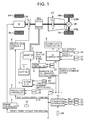
- the hybrid vehicle drive system in the first embodiment has engine E, flywheel FW, first clutch CL1, motor-generator MG, second clutch CL2, automatic transmission AT, propeller shaft PS, differential DF, left drive shaft DSL right drive shaft DSR, left rear wheel RL (drive wheel), and right rear wheel RR (drive wheel).
- FL represents the left front wheel
- FR represents the right front wheel.
- Engine E refers to a gasoline or diesel engine, and opening degree of its throttle valve is controlled according to a control command from engine controller 1 to be described later. Furthermore, the engine output shaft is provided with flywheel FW.
- First clutch CL1 is installed between engine E and motor-generator MG, and its engagement and release, including slip-engagement and slip-release, are controlled using a controlling hydraulic pressure generated by first clutch hydraulic unit 6 based on a control command from first clutch controller 5 to be described later. While a conventional clutch can be used as clutch CL1, any mechanism for transferring a variable torque between motor-generator MG and engine E can be employed.
- Motor-generator MG is a synchronous motor-generator in which a permanent magnet is embedded in a rotor, and a stator coil is wound around its stator. It is controlled using a 3-phase current generated by inverter 3 based on a control command from motor controller 2 to be described later.
- the motor-generator MG can operate as an electric motor which rotates upon receiving power from battery 4 (a state to be referred to as "power running,” hereinafter), and it can also operate as a generator that generates an electromotive force in the stator coil in order to charge battery 4 (a state referred to as "regeneration,” hereinafter). Furthermore, the motor-generator MG is linked to the input shaft of automatic transmission AT via a damper, not shown.
- Second clutch CL2 is installed between motor-generator MG and the drive wheels, and its engagement and release, including slip-engagement and slip-release, are controlled using a controlling hydraulic pressure generated by second clutch hydraulic unit 8 based on a control command from AT controller 7 to be described later.
- Automatic transmission AT is a transmission for automatically changing multistage gear ratios, for example, 5 speeds forward and 1 speed in reverse, according to a given vehicle speed and an accelerator pedal opening.
- the previously mentioned second clutch CL2 is not newly added as a dedicated clutch, and several frictional engagement elements out of multiple frictional engagement elements which are engaged at the respective gear stages of automatic transmission AT are diverted to this end.
- Output shaft of automatic transmission AT is then linked to left and right rear wheels RL and RR via propeller shaft PS, differential DF, left drive shaft DSL, and right drive shaft DSR.
- a wet multiplate clutch whose fluid flow rate and hydraulic pressure can be controlled continuously using a proportional solenoid, can be used for the first clutch CL1 and second clutch CL2.
- the hybrid drive system has 2 driving modes depending on the engagement/release state of first clutch CL1.
- first clutch CL1 The state in which first clutch CL1 is released corresponds to the electric car mode (to be abbreviated as "EV mode,” hereinafter) in which only the power of motor-generator MG is used as the power source for travel.
- EV mode electric car mode
- first clutch CL1 The state in which first clutch CL1 is engaged corresponds to the hybrid car mode (to be abbreviated as "HEV mode,” hereinafter) in which engine E is included in the power source for travel.
- HEV mode hybrid car mode
- the “HEV mode” comprises 3 driving modes, namely, “engine-based driving mode,” “motor-assisted driving mode,” and “driving/power generation mode.”
- engine E In “engine-based driving mode,” only engine E is used as the power source for driving the drive wheels.
- 2 power sources that is, engine E and motor-generator MG, are used for driving the drive wheels.
- drive wheels RR and RL are driven using engine E as the power source, and motor-generator MG functions as a generator at the same time. While traveling at a steady speed and during an acceleration, the power of engine E is used to let motor-generator MG function as a generator. In addition, braking energy is regenerated during deceleration so that motor-generator MG generates electricity to recharge battery 4.
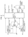
- the hybrid vehicle control system in the first embodiment is configured with engine controller 1, motor controller 2, inverter 3, battery 4, first clutch controller 5, first clutch hydraulic unit 6, AT controller 7, second clutch hydraulic unit 8, brake controller 9, and integration controller 10. Furthermore, engine controller 1, motor controller 2, first clutch controller 5, AT controller 7, brake controller 9, and integration controller 10 are connected to one another via CAN communication line 11 which allows information to be exchanged among them.
- Engine controller 1 receives engine rpm information from engine rpm sensor 12 as an input and outputs a command for controlling engine operating point Ne or Te to a throttle valve actuator, not shown, according to a target engine torque command from integration controller 10, for example.
- the information pertaining to engine rpm Ne is supplied to integration controller 10 via CAN communication line 11.
- Motor controller 2 receives information from resolver 13 which detects a given rotational position of the rotor of motor-generator MG as an input, and outputs a command for controlling motor operating point Nm or Tm for motor-generator MG to inverter 3 according to a target motor-generator torque command from integration controller 10.
- the motor controller 2 monitors the battery SOC which indicates the state of charge of battery 4; this battery SOC information is used for controlling motor-generator MG, and it is also supplied to integration controller 10 via CAN communication line 11.
- First clutch controller 5 receives sensor data from first clutch hydraulic pressure sensor 14 and first clutch stroke sensor 15 as inputs and outputs a command for engaging/releasing first clutch CL1 to first clutch hydraulic unit 6 according to a first clutch control command from integration controller 10.
- the information pertaining to first clutch stroke C1S is supplied to integration controller 10 via CAN communication line 11.
- AT controller 7 receives data from accelerator pedal opening sensor 16, vehicle speed sensor 17, and second clutch hydraulic pressure sensor 18 as inputs and outputs a command for engaging/releasing second clutch CL2 to second clutch hydraulic unit 8 provided inside an AT hydraulic control valve according to a second clutch control command from integration controller 10.
- the data pertaining to accelerator pedal opening AP and vehicle speed VSP are supplied to integration controller 10 via CAN communication line 11.
- Brake controller 9 receives data from vehicle speed sensor 19, which detects the respective wheel speeds of the 4 wheels, and brake stroke sensor 20 as inputs and performs regenerative collaborative brake control according to a regenerative collaborative control command from integration controller 10; for example, when the regenerative braking force alone is not sufficient for the required braking force that is obtained from brake stroke BS when the brake is pressed down, a mechanical braking force (a hydraulic braking force and/or a motor-based braking force) is used to compensate for this insufficiency.
- a mechanical braking force a hydraulic braking force and/or a motor-based braking force
- Integration controller 10 functions to govern the overall fuel consumption of the vehicle so that the vehicle travels with the optimum efficiency. It receives as inputs data from motor rpm sensor 21 which detects motor rpm Nm, second clutch output rpm sensor 22 which detects second clutch output rpm N2out, second clutch torque sensor 23 which detects second clutch torque TCL2, and brake hydraulic pressure sensor 24 and the data obtained via CAN communication line 11 as inputs.
- Integration controller 10 carries out engine E start control using the control command to engine controller 1, motor-generator MG start control using the control command to motor controller 2, first clutch CL1 engagement/release control using the control command to first clutch controller 5, and second clutch engagement/release control CL2 using the control command to AT controller 7.
- Integration controller 10 comprises target driving force computation part 100, mode selection part 200, target charge/discharge computation part 300, operating point command part 400, and speed control part 500.
- Target driving force computation part 100 computes target driving force tFo0 from accelerator pedal opening APO and vehicle speed VSP using the target driving force map shown in Figure 3.
- a request to start engine E is made when the operating point determined based on the torque required by vehicle and the motor rpm has crossed an engine start request line in the engine start/stop map when "EV mode" is selected; and a request to stop engine E is made when the operating point determined based on the torque required by vehicle and the motor rpm has crossed an engine stop request line when "HEV mode” is selected.
- the value of the torque on the engine start request line is referred to as the "EV travel-enabling torque" or “torque enabling EV travel”.
- EV travel-enabling torque is a threshold value calculated as explained below.
- Target charge/discharge computation part 300 computes target charge/discharge power tP from the battery SOC using the target charge/discharge amount map shown in Figure 5.
- Operating point command part 400 computes a transitional target engine torque, a target motor-generator torque, a target second clutch torque capacity, a target automatic transmission shift, and a first clutch solenoid current command are based on accelerator pedal opening APO, target driving force tFo0, the target mode, vehicle speed VSP, and target charge/discharge power tP as the targets for reaching the operating points.
- the target second clutch torque capacity and the target automatic transmission shift are used to drive a solenoid valve provided inside automatic transmission AT in order to achieve them.
- FIGS. 6-9 are flow charts showing the flow of driving mode transition control processing executed by integration controller 10.
- Driving mode selection processing Figure 6
- control processing while in the EV mode Figure 7
- control processing while in the HEV mode Figure 8
- the engine start mode when making the transition from EV mode to HEV mode Figure 9
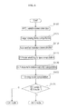
- FIG. 6 is a flow chart showing the driving mode selection processing executed by integration controller 10. The respective steps will be explained below.
- Step S100 Accelerator pedal opening APO and vehicle speed VSP are detected in Step S100, and process flow continues to Step S105.
- Step S100 Once accelerator pedal opening APO and vehicle speed VSP are detected in Step S100, target driving force tFo0 is computed from accelerator pedal opening APO and vehicle speed VSP in Step S105, and process flow continues to Step S110.
- Step S105 determines whether the intention to accelerate is weak or strong.
- Step S110 acceleration intention determination module
- the intention to accelerate is a measure of how quickly the driver is attempting to make the vehicle accelerate.
- the intention to accelerate determined based on one or more driving conditions, such as accelerator pedal opening, speed, and torque required by the vehicle, for example.
- Techniques that can be used to determine driver's intention to accelerate can include one or more of the following:
- Step S115 the EV travel-enabling torque is set at a rather low torque when the intention to accelerate is strong, or the EV travel-enabling torque is set at a rather high torque when the intention to accelerate is weak, and process flow continues to Step S120 (travel-enabling torque setting module).
- the engine start request line in the engine start/stop selection map is set such that a request is made to start the engine at a low vehicle required torque value when the intention to accelerate is strong, and a request is made to start the engine at a high vehicle required torque value when the intention to accelerate is weak, as shown in Figure 10.
- Step S115 the maximum torque capacity of clutch CL1 at the time of engagement of first clutch CL1 is computed in Step S120 by subtracting the EV travel-enabling torque from the maximum torque of motor-generator MG, and process flow continues to Step S122.
- Step S122 the target engine shaft driving torque is computed by dividing the target driving force tFo0 by the gear ratio, the target engine shaft driving torque and the EV travel-enabling torque are compared, "1" is output when target engine shaft driving torque > EV travel-enabling torque, or "0" is output when target engine shaft driving force ⁇ EV travel-enabling torque, and process flow continues to Step S125.
- Step S122 in Step S122, in Step 125 a transition is made to "EV mode” ( Figure 7) when "0" is output as a result of the driving mode computation, or a transition is made to "HEV mode” ( Figure 8) when "1" is output as a result of the driving mode computation.
- EV mode Figure 7
- HEV mode Figure 8
- Figure 7 is a flow chart showing the control carried out by integration controller 10 while in EV mode. The respective steps will be explained below.
- Step S130 Whether second clutch CL2 is engaged or not is determined in Step S130; if Yes process flow continues to Step S140, or if No process flow continues to Step S135.
- Step S130 When a determination is made in Step S130 that second clutch CL2 is not engaged, a command is issued in Step S135 to increase the hydraulic pressure applied to second clutch CL2 to engage it, and process flow continues to Step S140.
- Step S130 When a determination is made that clutch CL2 is engaged in Step S130, or after CL2 engagement control is finished in Step S135, whether engine E is stopped or not is determined in Step S140; if Yes process flow continues to Step S150, or if No process flow continues to Step S145.
- Step S140 When a determination is made in Step S140 that engine E is not stopped, a fuel cut-off signal is issued in Step S145, and process flow continues to Step S150.
- Step S140 When a determination is made in Step S140 that the engine is stopped, or after the engine is stopped in Step S145, whether first clutch CL1 is released or not is determined in Step S150; if Yes process flow continues to Step S160, if No or process flow continues to Step S155.
- Step S150 When a determination is made in Step S150 that CL1 is engaged, control is carried out in Step S155 to reduce the hydraulic pressure applied to first clutch CL1 so as to release it, and process flow continues to Step S160.
- Step S150 determines whether CL1 is released, or after CL1 is released in Step S155.
- the torque required of motor-generator MG is computed in Step S160 from the torque required by the vehicle and the gear ratio, and process flow continues to Step S165.
- Step 165 a command for obtaining the required torque from motor-generator MG is output to motor controller 2, and process flow passes to Return.
- FIG. 8 is a flow chart showing the control executed by integration controller 10 while in the HEV mode. The respective steps will be explained below.
- Step S170 Whether engine E has been started or not is determined in Step S170; if Yes process flow continues to Step S172, or if No a transition is made to the engine start mode ( Figure 9).
- Step S170 When a determination is made in Step S170 that the engine has been started, whether or not second clutch CL2 is engaged is determined in Step S172; if Yes process flow continues to Step S175, or if No process flow continues to Step S174.
- Step S172 When a determination is made in Step S172 that CL2 is not engaged, the hydraulic pressure supplied to second clutch CL2 is increased to engage second clutch CL2 in Step S174, and process flow continues to Step S175.
- Step S172 When a determination is made in Step S172 that CL2 is engaged, or after CL2 is engaged in Step S174, the portion of the driving torque required from the engine is computed in Step S175 based on the torque required by the vehicle and the gear ratio, an engine torque for generating electricity is further computed in response to a charge request which reflects the battery SOC shown in Figure 5, and the torque obtained by combining these is used as the torque required of the engine, and process flow continues to Step S180.
- Step S175 a torque value obtained by adding an engine E response delay is output as a torque command to engine controller 1 in Step S180, and process flow continues to Step S185.
- Step S180 the torque required of motor-generator MG is computed by subtracting the engine torque command value from the target engine shaft driving torque which was computed by dividing the target driving force tFo0 by the gear ratio in Step S185, and process flow continues to Step S190.
- Step S185 an MG torque command for obtaining the required MG torque is output to motor controller 2 in Step S190, and process flow passes to Return.
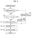
- Figure 9 is a flow chart showing the engine start mode processing executed by integration controller 10 when making the transition from EV mode to HEV mode. The respective steps will be explained below.
- Step S195 whether the input-output differential rotation of second clutch CL2 matches a prescribed value or not is determined; if Yes process flow continues to Step S205, or if No process flow continues to Step S200.
- Step S195 When a determination is made in Step S195 that the input-output differential rotation of second clutch CL2 does not match the prescribed value, the hydraulic pressure for engaging second clutch CL2 is reduced in Step S200 to the level at which the target driving force can be transmitted, the torque of motor-generator MG is regulated to bring the differential rotation of second clutch CL2 to the prescribed value, and process flow continues to Step S220.
- Step S195 When a determination is made in Step S195 that the differential rotation of CL2 matches the prescribed value, whether first clutch CL1 is engaged or not is determined in Step S205; if Yes process flow continues to Step S215, or if No process flow continues to Step S210.
- Step S205 When a determination is made in Step S205 that CL1 is not engaged, the hydraulic pressure of first clutch CL1 is increased in Step S210 to engage it, the engine rpm is reduced to an rpm equal to or higher than that at which the engine can be still started, and process flow continues to Step S220.
- first clutch CL1 engagement control the hydraulic pressure of first clutch CL1 is controlled such that the maximum torque capacity of clutch CL1 at the time of engagement of CL1 computed in the Step S120 is not exceeded.
- Step S205 When a determination is made in Step S205 that CL1 is engaged, fuel is injected in Step S215 to start engine E, and process flow continues to Step S220.
- Step S225 Following clutch semi-engagement control of CL2 in Step S200, the engagement control of CL1 in Step S210, or the engine start control in Step S215, because the "EV mode" is basically used for traveling while in the engine start mode, the required MG torque is computed in Step S220 from the required vehicle driving force and the gear ratio, and process flow continues to Step S225.
- Step S220 Once the required MG torque is computed in Step S220, an MG torque command for obtaining the required MG torque is output to motor controller 2 in Step S225, and process flow passes to Return.
- the motor-generator In a hybrid vehicle in which the clutch is installed between the engine and the motor-generator, the motor-generator is used as a starter motor when making the transition from "EV mode” to "HEV mode” by starting the engine, and the engine is started by engaging the clutch installed between the engine and the motor-generator.
- the torque used as the driving torque ends up being limited to the torque obtained by subtracting the engine starting torque from the maximum torque of the motor-generator.
- the clutch installed between the engine and the motor-generator is controlled to engage at a high torque capacity in response to an engine start request despite the fact that the driver's intention to accelerate is weak, the driving torque becomes insufficient since the major part of the torque generated by the motor-generator is transmitted to the engine side, and sufficient "EV mode" travel cannot be realized, resulting in the problems of increased fuel consumption and reduced drivability.
- the hybrid vehicle driving mode transition controller of the first embodiment is designed such that setting a driving zone for the "EV mode" in accordance with the driver's acceleration intentions and good engine startability can be assured when making the transition from "EV mode” to "HEV mode.”
- the hybrid vehicle driving mode transition controller of the first embodiment can control the maximum torque capacity of clutch CL1 at the time of engagement of first clutch CL1 such that the weaker the driver's intention to accelerate is determined to be, the lower the rate of engine rpm rise becomes when making the transition from "EV mode" to "HEV mode.”
- the maximum torque capacity of clutch CL1 at the time of engagement of first clutch CL1 is increased so that the rate of change in the rpm of the engine when starting is faster. This starts the engine more quickly and reduces the driving zone using the "EV mode.” Because the engine is started more quickly, the torques of engine E and motor-generator MG are combined in order to accelerate using the greater driving force, so that the drivability can be improved.
- engine E is started slowly by reducing the maximum torque capacity of clutch CL1 at the time of engagement of first clutch CL1 so as to expand the driving zone using the "EV mode," so that fuel consumption and drivability can be improved.
- Step S122 the target engine shaft driving torque is computed by dividing target driving force tFo0 by the gear ratio, and the target engine shaft driving torque and the EV travel-enabling torque are compared, whereby "1" is output when the target engine shaft driving torque > EV travel-enabling torque, or "0" is output when the target engine shaft driving torque ⁇ EV travel-enabling torque.
- Step S125 a transition is made to the "EV mode” ( Figure 7) if "0" is output as a result of the driving mode computation, or a transition is made to the "HEV mode” ( Figure 8) if "1" is output as a result of the driving mode computation.
- Step S130 when the target engine shaft driving torque ⁇ EV travel-enabling torque, and "EV mode" is selected, process flow advances from Step S130 ⁇ (Step S135) ⁇ Step S140 (Step S145) ⁇ Step 150 (Step S155); process flow advances to Step S160 when the conditions that second clutch CL2 is engaged, the engine is stopped, and first clutch CL1 is released are met; the torque required of motor-generator MG is computed from the torque required by the vehicle and the gear ratio; and a command for obtaining the torque required of motor-generator MG is output to motor controller 2 in the next step, that is, Step S165.
- Step S200 the hydraulic pressure for engaging second clutch CL2 is reduced to the level at which the target driving force can be transmitted so as to control the torque of motor-generator MG such that the differential rotation of second clutch CL2 matches the prescribed value.
- Step S210 the hydraulic pressure of first clutch CL1 is increased to engage it, and the engine rpm is brought up to the rpm at which the engine can be started.
- the hydraulic pressure of first clutch CL1 is controlled such that the maximum torque capacity of clutch CL1 at the time of engagement of CL1 computed in Step S120 is not exceeded.
- Step S195 when the differential rotation of second clutch CL2 matches the prescribed value, and first clutch CL1 is engaged while in the engine start mode, process flow advances from Step S195 ⁇ Step S205 ⁇ Step S215 ⁇ Step S220 ⁇ Step S225 in the flow chart in Figure 9, with fuel being injected in Step S215 to start engine E.
- the required MG torque is computed from the required vehicle driving force and the gear ratio in Step S220, and an MG torque command for obtaining the required MG torque is output to motor controller 2 in Step S225.
- Step S170 ⁇ Step S172 ⁇ (Step S174) ⁇ Step S175 ⁇ Step S180 ⁇ Step S185 ⁇ Step S190 in the flow chart in Figure 8.
- Step S175 a torque value obtained by adding a response delay of engine E is output as a torque command to engine controller 1 in Step S180, the required MG torque is computed in Step S185, and an MG torque command for obtaining the required MG torque is output to motor controller 2 in Step S190.
- Step S110 When a determination is made in Step S110 that the driver's intention to accelerate is strong when the driver presses the accelerator pedal down abruptly while traveling in "EV mode," for example, the EV travel-enabling torque is set at a rather low torque value in the next step, that is, Step S115, based on the determination that the driver's intention to accelerate is strong.
- Step S120 the maximum torque capacity of clutch CL1 at the time of engagement of first clutch CL1, based on the high value, is computed by subtracting the EV travel-enabling torque, based on the rather low torque value of the maximum torque of motor-generator MG, and a torque command for obtaining the maximum torque capacity of clutch CL1 at the time of engagement of first clutch CL1 based on the high value is output to first clutch controller 6 under the engine start mode.
- clutch engagement control is performed to obtain the maximum torque capacity of clutch CL1 at the time of engagement of first clutch CL1, based on the high value, while in the engine start mode, an engine starting torque for offsetting the engine friction and the rotational inertia is transmitted from motor-generator MG to engine E via first clutch CL1 in order to start engine E quickly.
- the rate of engine E rpm rise is increased to reduce the "EV mode" zone in order to achieve the mode transition to the "HEV mode” highly responsively, so that a large driving force reflecting the intention to accelerate, as indicated by driver operation of the accelerator, can be used to accelerate, resulting in improved drivability.
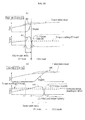
- Figure 11 (a) provides time charts showing characteristics in terms of transmission input rpm, motor-generator rpm, engine rpm, motor-generator torque, and first clutch torque capacity when a mode transition is made from "EV mode” to "HEV mode” if a determination is made that the driver's intention to accelerate is strong.
- control for obtaining maximum torque capacity of clutch CL1 at the time of engagement of first clutch CL1, based on the high value, is executed during the period between time t1, where the driving mode is switched from the "EV mode” to the "HEV mode” when the target engine shaft driving torque exceeds the low EV travel-enabling torque so as to initiate the engine start mode, and time t2, at which the engine start mode is ended, engine E receives the engine starting torque from motor-generator MG so as to increase the engine rpm at a high rate of rise, so that the engine start mode is ended quickly.
- Step S110 When a determination is made in Step S110 that the driver's intention to accelerate is weak because the driver eases up on the accelerator pedal while traveling in the "EV mode," for example, the EV travel-enabling torque is set at a rather high torque value in the next step, that is, Step S115, based on the determination that the driver's intention to accelerate is weak.
- Step S120 the maximum torque capacity of clutch CL1 at the time of engagement of first clutch CL1, based on the low value, is computed by subtracting the EV travel-enabling torque based on the rather high torque value from motor-generator MG, and a torque command for obtaining the maximum torque capacity of clutch CL1 at the time of engagement of first clutch CL1, based on the low value, is output to first clutch controller 6 under the engine start mode.
- the clutch engagement control for obtaining maximum torque at the time of engagement of first clutch CL1, based on the low value, is carried out in the engine start mode, the engine starting torque transmitted from motor-generator MG to engine E via first clutch CL1 is low, so that it take a long time for engine E to start slowly.
- the rate of engine E rpm rise is reduced in accordance with the weak intention to accelerate as indicated by accelerator operation by the driver, so that the "EV mode" zone is expanded, improving fuel consumption and drivability.
- Figure 11(b) is a time chart showing the characteristics in terms of transmission input rpm, motor-generator rpm, engine rpm, motor-generator torque, and first clutch torque capacity when a mode transition is made from "EV mode” to "HEV mode” when a determination is made that the driver's intention to accelerate is weak.
- the driving mode is not switched from “EV mode” to "HEV mode” even at time t1, when the target engine shaft driving torque has exceeded the low EV travel-enabling torque, such as would be required if the driver's intention to accelerate were strong.
- the driving mode is switched from "EV mode” to "HEV mode” at time t3, when the target engine shaft driving torque has exceeded the high EV travel-enabling torque, as is required when the driver's intention to accelerate is weak, and control for obtaining the maximum torque capacity of clutch CL1 at the time of engagement of first clutch CL1, based on the low value, is executed during the period of time between time t3, at which the engine start mode is initiated, and time t4 at which the engine start mode is ended.
- engine E receives lower engine starting torque from motor-generator MG, so that the engine rpm increases gradually, and it takes a longer time to end the engine start mode.
- time t3, at which the engine start mode is initiated comes later than time t1 at which the engine start mode is initiated when the driver's intention to accelerate is strong.
- the length of time between time t3, at which the engine start mode is initiated, and time t4, at which the engine start mode is ended becomes longer than the duration of time between t1, at which the engine start mode is initiated, and time t2, at which the engine start mode is ended, when the driver's intention to accelerate is strong.
- the expanded zone extending up to time t4, at which the engine start mode is ended becomes the driving zone using the "EV mode”; and the driving mode is switched to the "HEV mode" at time t4 at which the engine start mode is ended.
- the maximum torque at the time of engagement of the first clutch is controlled by the driving mode transition control module based on whether the driver's intention to accelerate is weak or strong
- multistage control involving 3 or more stages or stageless control can be adopted in place of 2-stage control.
- the driving mode transition control module sets the "EV mode" travel-enabling torque at a rather low torque value when the intention to accelerate is strong and sets the "EV mode" travel-enabling torque at a rather high torque value when the intention to accelerate is weak
- the travel-enabling torque can be determined according to the intention to accelerate by means of multistage control involving 3 or more stages, or by stageless control.
- the invention can be practiced with any driving mode transition control module that is capable of controlling the maximum torque capacity of clutch installed between the engine and the motor-generator such that the weaker the driver's intention to accelerate is determined to be, the slower the rate of engine rpm rise becomes when making the mode transition from the "EV mode" to the "HEV mode"
- the invention can also be applied to a front-wheel-drive or 4-wheel-drive hybrid vehicle.
- a clutch built into an automatic transmission was utilized as the second clutch
- the second clutch can be added between the motor-generator and the transmission, or the second clutch can be installed between the transmission and the drive wheels, as shown in Figure 12.
- it can also be applied to a hybrid vehicle in which only the first clutch (engine clutch) is installed between the engine and the motor-generator.
- any hybrid vehicle equipped with an engine, a motor-generator, and a clutch installed between the engine and the motor-generator, wherein the engine is started by engaging the clutch while using the motor-generator as an engine starter motor when making the mode transition from the electric car mode, in which only the motor-generator is used as the power source, to the hybrid car mode, in which the engine is included as part of the power source.
- the driver can be a human, with a subjective intention to accelerate, or a machine that has determined to control the vehicle to achieve a higher or lower rate of acceleration.
- the machine can communicate its intention to accelerate to integration controller 10, which in such case does not need to rely on APO data.
Landscapes
- Engineering & Computer Science (AREA)
- Chemical & Material Sciences (AREA)
- Combustion & Propulsion (AREA)
- Transportation (AREA)
- Mechanical Engineering (AREA)
- Automation & Control Theory (AREA)
- Hybrid Electric Vehicles (AREA)
- Electric Propulsion And Braking For Vehicles (AREA)
- Control Of Vehicle Engines Or Engines For Specific Uses (AREA)
- Hydraulic Clutches, Magnetic Clutches, Fluid Clutches, And Fluid Joints (AREA)
Applications Claiming Priority (1)
| Application Number | Priority Date | Filing Date | Title |
|---|---|---|---|
| JP2006090028A JP2007261442A (ja) | 2006-03-29 | 2006-03-29 | ハイブリッド車両の運転モード遷移制御装置 |
Publications (1)
| Publication Number | Publication Date |
|---|---|
| EP1839986A1 true EP1839986A1 (fr) | 2007-10-03 |
Family
ID=38198321
Family Applications (1)
| Application Number | Title | Priority Date | Filing Date |
|---|---|---|---|
| EP07104966A Withdrawn EP1839986A1 (fr) | 2006-03-29 | 2007-03-27 | Contrôle de mode de conduite |
Country Status (4)
| Country | Link |
|---|---|
| US (1) | US20070227791A1 (fr) |
| EP (1) | EP1839986A1 (fr) |
| JP (1) | JP2007261442A (fr) |
| CN (1) | CN101045453A (fr) |
Cited By (16)
| Publication number | Priority date | Publication date | Assignee | Title |
|---|---|---|---|---|
| EP2055573A2 (fr) | 2007-11-02 | 2009-05-06 | GM Global Technology Operations, Inc. | Système de contrôle pour la gestion de couple de moteur thermique dans un système de transmission hybride |
| CN101683851A (zh) * | 2008-09-24 | 2010-03-31 | 加特可株式会社 | 混合动力车辆的控制装置 |
| EP1970240A3 (fr) * | 2007-03-12 | 2010-04-14 | Nissan Motor Company Limited | Système de contrôle du démarrage du moteur pour véhicule hybride |
| WO2010089247A1 (fr) * | 2009-02-09 | 2010-08-12 | Zf Friedrichshafen Ag | Procédé d'accouplement d'un moteur à combustion interne d'une transmission hybride parallèle |
| EP2226227A1 (fr) * | 2007-11-30 | 2010-09-08 | Bosch Corporation | Procédé de commande de système hybride |
| FR2962096A1 (fr) * | 2010-07-02 | 2012-01-06 | Peugeot Citroen Automobiles Sa | Procede et appareil de controle/commande d'un groupe motopropulseur hybride |
| CN101508292B (zh) * | 2007-11-02 | 2012-05-30 | 通用汽车环球科技运作公司 | 用于在动力系内控制电压的方法 |
| CN102806908A (zh) * | 2011-06-02 | 2012-12-05 | 通用汽车环球科技运作有限责任公司 | 用于响应于附件负荷而操作动力系统的方法和装置 |
| WO2017148474A1 (fr) * | 2016-02-29 | 2017-09-08 | Schaeffler Technologies AG & Co. KG | Procédé permettant de faire démarrer un moteur à combustion interne de véhicule hybride et unité de commande pour la mise en oeuvre dudit procédé |
| EP2634052A4 (fr) * | 2010-10-26 | 2018-04-18 | Nissan Motor Co., Ltd | Dispositif de commande de démarrage d'un moteur thermique pour véhicule électrique hybride |
| FR3061468A1 (fr) * | 2017-01-03 | 2018-07-06 | Peugeot Citroen Automobiles Sa. | Procede de controle d'un groupe motopropulseur hybride pour le franchissement d'un obstacle |
| EP3023284B1 (fr) * | 2014-11-18 | 2020-08-05 | Saic Motor Corporation Ltd. | Système d'entraînement de puissance hybride et procédé correspondant |
| CN112677953A (zh) * | 2021-01-07 | 2021-04-20 | 浙江吉利控股集团有限公司 | 双电机混合动力系统中发动机的启动方法和装置及车辆 |
| CN113173154A (zh) * | 2020-08-21 | 2021-07-27 | 长城汽车股份有限公司 | 用于混合动力车辆的动力分配管理方法及装置 |
| EP3835158A4 (fr) * | 2018-09-13 | 2021-10-13 | Mazda Motor Corporation | Dispositif de commande de démarrage de moteur pour véhicule hybride, et véhicule hybride |
| EP4155145A4 (fr) * | 2020-09-07 | 2023-11-29 | Great Wall Motor Company Limited | Procédé et dispositif de conduite pour véhicule hybride, et véhicule |
Families Citing this family (69)
| Publication number | Priority date | Publication date | Assignee | Title |
|---|---|---|---|---|
| DE102007026354A1 (de) * | 2007-06-06 | 2008-12-11 | Bayerische Motoren Werke Aktiengesellschaft | Verfahren zur Steuerung eines Schubbetriebs eines Kraftfahrzeugs, Steuereinrichtung zur Durchführung des Verfahrens sowie Kraftfahrzeug |
| KR100992781B1 (ko) * | 2007-12-13 | 2010-11-05 | 기아자동차주식회사 | 하이브리드 차량의 클러치 결합제어를 위한 시스템과 그방법 |
| JP2009184382A (ja) * | 2008-02-01 | 2009-08-20 | Toyota Motor Corp | ハイブリッド自動車およびその制御方法 |
| JP2009184383A (ja) * | 2008-02-01 | 2009-08-20 | Toyota Motor Corp | ハイブリッド自動車およびその制御方法 |
| JP5680279B2 (ja) * | 2008-03-06 | 2015-03-04 | 日産自動車株式会社 | ハイブリッド車両のエンジン停止制御装置 |
| JP5200733B2 (ja) * | 2008-07-29 | 2013-06-05 | 日産自動車株式会社 | ハイブリッド車両のクラッチ制御装置 |
| US8042632B2 (en) * | 2008-10-15 | 2011-10-25 | GM Global Technology Operations LLC | Creep mode propulsion for stop-start hybrid vehicles |
| JP5309962B2 (ja) * | 2008-12-19 | 2013-10-09 | 日産自動車株式会社 | ハイブリッド車両の制御装置 |
| US9821865B2 (en) | 2010-04-15 | 2017-11-21 | Yvon Martel | Compact pulling apparatus |
| CN102294999A (zh) * | 2010-06-23 | 2011-12-28 | 北汽福田汽车股份有限公司 | 用于四轮驱动汽车的驱动模式控制系统 |
| JP5556523B2 (ja) * | 2010-09-13 | 2014-07-23 | トヨタ自動車株式会社 | 車両の制御装置 |
| JP2012081910A (ja) * | 2010-10-14 | 2012-04-26 | Toyota Motor Corp | 車両用エンジン始動制御装置 |
| JP5273121B2 (ja) * | 2010-10-19 | 2013-08-28 | 株式会社デンソー | 発進支援装置 |
| US9026290B2 (en) | 2010-10-21 | 2015-05-05 | Hino Motors, Ltd. | Driving mode switch control device, hybrid vehicle, driving mode switch control method, and computer program |
| CN103282253B (zh) * | 2010-10-21 | 2015-09-02 | 日产自动车株式会社 | 混合动力车辆的发动机起动控制设备 |
| US8924063B2 (en) * | 2010-10-22 | 2014-12-30 | Hino Motors, Ltd. | Vehicle, control method, and computer program |
| EP2631132B1 (fr) * | 2010-10-22 | 2015-09-23 | Hino Motors Ltd. | Véhicule, procédé de commande et programme |
| JP2012091620A (ja) * | 2010-10-26 | 2012-05-17 | Nissan Motor Co Ltd | ハイブリッド車両のエンジン始動制御装置 |
| CN102085796A (zh) * | 2011-01-07 | 2011-06-08 | 上海交通大学 | 模块化电动汽车 |
| US9352739B2 (en) * | 2011-02-15 | 2016-05-31 | GM Global Technology Operations LLC | Method for operating a hybrid vehicle |
| JP2012240566A (ja) * | 2011-05-20 | 2012-12-10 | Nissan Motor Co Ltd | ハイブリッド車両の電気走行制御装置 |
| JP5747724B2 (ja) * | 2011-08-04 | 2015-07-15 | トヨタ自動車株式会社 | 車両および車両の制御方法 |
| JP2013035441A (ja) * | 2011-08-09 | 2013-02-21 | Nissan Motor Co Ltd | ハイブリッド車両の制御装置 |
| KR101521761B1 (ko) * | 2011-08-09 | 2015-05-19 | 도요타지도샤가부시키가이샤 | 하이브리드 차량의 제어 장치 |
| JP5682515B2 (ja) * | 2011-09-08 | 2015-03-11 | 三菱自動車工業株式会社 | ハイブリッド電気自動車の制御装置 |
| JP5831555B2 (ja) * | 2011-11-16 | 2015-12-09 | トヨタ自動車株式会社 | 車両の制御装置 |
| US9550491B2 (en) | 2012-01-04 | 2017-01-24 | Toyota Jidosha Kabushiki Kaisha | Vehicle control apparatus |
| US9290173B2 (en) | 2012-01-20 | 2016-03-22 | Toyota Jidosha Kabushiki Kaisha | Engine start control device for hybrid vehicle |
| US9421967B2 (en) | 2012-03-13 | 2016-08-23 | Nissan Motor Co., Ltd. | Control device for hybrid vehicle |
| US9227620B2 (en) | 2012-03-15 | 2016-01-05 | Nissan Motor Co., Ltd. | Engine start control device and engine start control method for hybrid electric vehicle |
| JP6110621B2 (ja) * | 2012-09-27 | 2017-04-05 | 富士重工業株式会社 | ハイブリッド車両の駆動装置 |
| WO2014054724A1 (fr) * | 2012-10-04 | 2014-04-10 | 日産自動車株式会社 | Dispositif de commande de démarrage pour véhicule hybride |
| BR112015008545B1 (pt) | 2012-10-19 | 2021-06-22 | Yvon Martel | Unidade de acionamento de transporte |
| KR101846569B1 (ko) * | 2012-10-26 | 2018-04-09 | 현대자동차주식회사 | 하이브리드 차량의 제어방법 |
| GB2508669A (en) * | 2012-12-10 | 2014-06-11 | Jaguar Land Rover Ltd | A speed control system for a hybrid electric vehicle |
| JP6003758B2 (ja) * | 2013-03-26 | 2016-10-05 | トヨタ自動車株式会社 | ハイブリッド自動車 |
| JP6032351B2 (ja) * | 2013-04-04 | 2016-11-24 | 日産自動車株式会社 | ハイブリッド車両の制御装置 |
| KR102206902B1 (ko) * | 2013-07-11 | 2021-01-22 | 이본 마르텔 | 소형 견인장치 |
| US9393950B2 (en) * | 2013-07-22 | 2016-07-19 | Ford Global Technologies, Llc | Methods and systems for restarting an engine |
| JP6028689B2 (ja) * | 2013-08-05 | 2016-11-16 | トヨタ自動車株式会社 | 移動情報処理装置、移動情報処理方法及び運転支援システム |
| JP6003843B2 (ja) * | 2013-08-08 | 2016-10-05 | トヨタ自動車株式会社 | ハイブリッド車両の制御装置 |
| JP6268665B2 (ja) * | 2013-08-09 | 2018-01-31 | スズキ株式会社 | ハイブリッド車の制御装置 |
| CN104842996B (zh) * | 2014-06-18 | 2017-10-10 | 北汽福田汽车股份有限公司 | 一种混合动力汽车换挡方法及系统 |
| US9810273B2 (en) * | 2014-07-30 | 2017-11-07 | Ford Global Technologies, Llc | Methods and system for applying a driveline disconnect clutch |
| DE102014012319B4 (de) * | 2014-08-19 | 2024-05-02 | Audi Ag | Verfahren zum Betreiben eines Kraftfahrzeugs, Kraftfahrzeug und Computerprogramm |
| US10272741B2 (en) * | 2014-11-13 | 2019-04-30 | Ford Global Technologies, Llc | Methods and system for heating a hybrid vehicle |
| CN104828063B (zh) * | 2014-12-19 | 2017-06-06 | 北汽福田汽车股份有限公司 | 混合动力汽车模式切换时的控制方法及其动力系统 |
| JP6488798B2 (ja) * | 2015-03-19 | 2019-03-27 | 日産自動車株式会社 | ハイブリッド車両の制御装置 |
| JP6477177B2 (ja) * | 2015-04-06 | 2019-03-06 | 日産自動車株式会社 | ハイブリッド車両の制御装置 |
| WO2016194172A1 (fr) * | 2015-06-03 | 2016-12-08 | 日産自動車株式会社 | Dispositif de commande de transition de mode pour véhicule hybride |
| CN105128848B (zh) * | 2015-09-15 | 2017-07-25 | 重庆长安汽车股份有限公司 | 一种行进间起动发动机的控制方法 |
| KR102237064B1 (ko) * | 2015-10-15 | 2021-04-06 | 현대자동차 주식회사 | 하이브리드 차량 및 그 제어 방법 |
| KR101714521B1 (ko) * | 2015-11-06 | 2017-03-22 | 현대자동차주식회사 | 하이브리드 자동차 및 그를 위한 효율적인 변속 제어 방법 |
| CN105774793B (zh) * | 2016-04-25 | 2018-01-05 | 清华大学 | 一种并联混合动力系统电机启动发动机模式切换控制方法 |
| CN106080581B (zh) * | 2016-08-16 | 2018-12-14 | 潍柴动力股份有限公司 | 一种混合动力汽车及该汽车的发动机起动控制方法 |
| JP6617668B2 (ja) * | 2016-09-12 | 2019-12-11 | トヨタ自動車株式会社 | ハイブリッド車両の制御装置 |
| DE102017214787A1 (de) * | 2017-08-23 | 2019-02-28 | Bayerische Motoren Werke Aktiengesellschaft | Impulsstart in einem Hybrid-Antriebsstrang |
| JP7024326B2 (ja) * | 2017-10-31 | 2022-02-24 | トヨタ自動車株式会社 | ハイブリッド車両 |
| CN108146509A (zh) * | 2017-12-21 | 2018-06-12 | 重庆飞特车辆技术有限公司 | 一种车体 |
| JP6741645B2 (ja) * | 2017-12-22 | 2020-08-19 | 株式会社Subaru | 車両の制御装置及び車両の制御方法 |
| JP6616817B2 (ja) * | 2017-12-27 | 2019-12-04 | 株式会社Subaru | 車両用制御装置 |
| JP7192217B2 (ja) * | 2018-02-28 | 2022-12-20 | スズキ株式会社 | 駆動力制御装置 |
| KR102515388B1 (ko) * | 2018-03-29 | 2023-03-30 | 현대자동차주식회사 | 차량 및 그 제어 방법 |
| JP7137361B2 (ja) * | 2018-06-04 | 2022-09-14 | 株式会社Subaru | ハイブリッド車両の制御装置 |
| CN113135176B (zh) * | 2020-07-06 | 2022-05-31 | 长城汽车股份有限公司 | 混合动力车辆的模式切换控制方法、装置和车辆 |
| KR20220063772A (ko) * | 2020-11-09 | 2022-05-18 | 현대자동차주식회사 | 고전압 배터리의 소비전력 제어 시스템 및 방법 |
| CN113022548B (zh) * | 2021-03-08 | 2022-11-18 | 江苏大学 | 一种混合动力汽车模式切换控制系统及其控制方法 |
| DE112021007745T5 (de) * | 2021-06-01 | 2024-04-18 | Schaeffler Technologies AG & Co. KG | Verfahren und Vorrichtung zur Motorstartsteuerung von Hybridfahrzeugen |
| CN113500922B (zh) * | 2021-09-13 | 2021-11-19 | 睿控智行汽车技术(南通)有限公司 | 基于功率需求预判的电动汽车启动控制方法和系统 |
Citations (5)
| Publication number | Priority date | Publication date | Assignee | Title |
|---|---|---|---|---|
| EP1052400A2 (fr) * | 1999-05-12 | 2000-11-15 | Nissan Motor Company, Limited | Dispositif d'arrêt et de redémarrage automatique pour moteur à combustion interne pour véhicule |
| US6209672B1 (en) | 1998-09-14 | 2001-04-03 | Paice Corporation | Hybrid vehicle |
| US20030001390A1 (en) | 2001-06-29 | 2003-01-02 | Phillips Anthony Mark | Method for starting an engine in a parallel hybrid electric vehicle |
| DE10353256B3 (de) | 2003-11-14 | 2005-03-31 | Barske, Heiko, Dr. | Hybridantriebssystem für ein Kraftfahrzeug |
| FR2875446A1 (fr) * | 2004-09-23 | 2006-03-24 | Peugeot Citroen Automobiles Sa | Systeme de controle du fonctionnement de moyens de motorisation hybride d'un vehicule automobile |
Family Cites Families (5)
| Publication number | Priority date | Publication date | Assignee | Title |
|---|---|---|---|---|
| IT1319883B1 (it) * | 2000-02-04 | 2003-11-12 | Fiat Ricerche | Procedimento e sistema di controllo della propulsione di unautoveicolo |
| US7407026B2 (en) * | 2000-10-11 | 2008-08-05 | Ford Global Technologies, Llc | Control system for a hybrid electric vehicle to anticipate the need for a mode change |
| JP3580260B2 (ja) * | 2001-03-01 | 2004-10-20 | 日産自動車株式会社 | 車両の制御装置 |
| JP2005138743A (ja) * | 2003-11-07 | 2005-06-02 | Nissan Motor Co Ltd | ハイブリッド車両の駆動力制御装置 |
| US6991585B2 (en) * | 2004-05-04 | 2006-01-31 | Ford Global Technologies, Llc | Torsional isolation of a convertless automatic transmission through slip control of friction clutch |
-
2006
- 2006-03-29 JP JP2006090028A patent/JP2007261442A/ja active Pending
-
2007
- 2007-03-23 CN CNA2007100871958A patent/CN101045453A/zh active Pending
- 2007-03-27 EP EP07104966A patent/EP1839986A1/fr not_active Withdrawn
- 2007-03-28 US US11/729,112 patent/US20070227791A1/en not_active Abandoned
Patent Citations (5)
| Publication number | Priority date | Publication date | Assignee | Title |
|---|---|---|---|---|
| US6209672B1 (en) | 1998-09-14 | 2001-04-03 | Paice Corporation | Hybrid vehicle |
| EP1052400A2 (fr) * | 1999-05-12 | 2000-11-15 | Nissan Motor Company, Limited | Dispositif d'arrêt et de redémarrage automatique pour moteur à combustion interne pour véhicule |
| US20030001390A1 (en) | 2001-06-29 | 2003-01-02 | Phillips Anthony Mark | Method for starting an engine in a parallel hybrid electric vehicle |
| DE10353256B3 (de) | 2003-11-14 | 2005-03-31 | Barske, Heiko, Dr. | Hybridantriebssystem für ein Kraftfahrzeug |
| FR2875446A1 (fr) * | 2004-09-23 | 2006-03-24 | Peugeot Citroen Automobiles Sa | Systeme de controle du fonctionnement de moyens de motorisation hybride d'un vehicule automobile |
Cited By (26)
| Publication number | Priority date | Publication date | Assignee | Title |
|---|---|---|---|---|
| EP1970240A3 (fr) * | 2007-03-12 | 2010-04-14 | Nissan Motor Company Limited | Système de contrôle du démarrage du moteur pour véhicule hybride |
| US8204659B2 (en) | 2007-03-12 | 2012-06-19 | Nissan Motor Co., Ltd. | Engine start control system for hybrid vehicle |
| CN101508292B (zh) * | 2007-11-02 | 2012-05-30 | 通用汽车环球科技运作公司 | 用于在动力系内控制电压的方法 |
| CN101480951B (zh) * | 2007-11-02 | 2012-12-12 | 通用汽车环球科技运作公司 | 用于混合动力系系统的发动机转矩管理的控制系统 |
| EP2055573A3 (fr) * | 2007-11-02 | 2010-09-29 | GM Global Technology Operations, Inc. | Système de contrôle pour la gestion de couple de moteur thermique dans un système de transmission hybride |
| EP2055573A2 (fr) | 2007-11-02 | 2009-05-06 | GM Global Technology Operations, Inc. | Système de contrôle pour la gestion de couple de moteur thermique dans un système de transmission hybride |
| EP2226227A4 (fr) * | 2007-11-30 | 2013-04-17 | Bosch Corp | Procédé de commande de système hybride |
| EP2226227A1 (fr) * | 2007-11-30 | 2010-09-08 | Bosch Corporation | Procédé de commande de système hybride |
| EP2168803A3 (fr) * | 2008-09-24 | 2010-12-01 | JATCO Ltd | Dispositif de contrôle d'un véhicule hybride avec régulation de la pression d'embrayage |
| US8282527B2 (en) | 2008-09-24 | 2012-10-09 | Jatco Ltd | Control apparatus for hybrid vehicle |
| CN101683851A (zh) * | 2008-09-24 | 2010-03-31 | 加特可株式会社 | 混合动力车辆的控制装置 |
| CN101683851B (zh) * | 2008-09-24 | 2014-09-24 | 加特可株式会社 | 混合动力车辆的控制装置 |
| WO2010089247A1 (fr) * | 2009-02-09 | 2010-08-12 | Zf Friedrichshafen Ag | Procédé d'accouplement d'un moteur à combustion interne d'une transmission hybride parallèle |
| US8529400B2 (en) | 2009-02-09 | 2013-09-10 | Zf Friedrichshafen Ag | Method for coupling an internal combustion engine of a parallel-hybrid drive train |
| FR2962096A1 (fr) * | 2010-07-02 | 2012-01-06 | Peugeot Citroen Automobiles Sa | Procede et appareil de controle/commande d'un groupe motopropulseur hybride |
| EP2634052A4 (fr) * | 2010-10-26 | 2018-04-18 | Nissan Motor Co., Ltd | Dispositif de commande de démarrage d'un moteur thermique pour véhicule électrique hybride |
| CN102806908A (zh) * | 2011-06-02 | 2012-12-05 | 通用汽车环球科技运作有限责任公司 | 用于响应于附件负荷而操作动力系统的方法和装置 |
| CN102806908B (zh) * | 2011-06-02 | 2015-09-30 | 通用汽车环球科技运作有限责任公司 | 用于响应于附件负荷而操作动力系统的方法 |
| EP3023284B1 (fr) * | 2014-11-18 | 2020-08-05 | Saic Motor Corporation Ltd. | Système d'entraînement de puissance hybride et procédé correspondant |
| WO2017148474A1 (fr) * | 2016-02-29 | 2017-09-08 | Schaeffler Technologies AG & Co. KG | Procédé permettant de faire démarrer un moteur à combustion interne de véhicule hybride et unité de commande pour la mise en oeuvre dudit procédé |
| FR3061468A1 (fr) * | 2017-01-03 | 2018-07-06 | Peugeot Citroen Automobiles Sa. | Procede de controle d'un groupe motopropulseur hybride pour le franchissement d'un obstacle |
| EP3835158A4 (fr) * | 2018-09-13 | 2021-10-13 | Mazda Motor Corporation | Dispositif de commande de démarrage de moteur pour véhicule hybride, et véhicule hybride |
| CN113173154A (zh) * | 2020-08-21 | 2021-07-27 | 长城汽车股份有限公司 | 用于混合动力车辆的动力分配管理方法及装置 |
| CN113173154B (zh) * | 2020-08-21 | 2022-04-22 | 长城汽车股份有限公司 | 用于混合动力车辆的动力分配管理方法及装置 |
| EP4155145A4 (fr) * | 2020-09-07 | 2023-11-29 | Great Wall Motor Company Limited | Procédé et dispositif de conduite pour véhicule hybride, et véhicule |
| CN112677953A (zh) * | 2021-01-07 | 2021-04-20 | 浙江吉利控股集团有限公司 | 双电机混合动力系统中发动机的启动方法和装置及车辆 |
Also Published As
| Publication number | Publication date |
|---|---|
| CN101045453A (zh) | 2007-10-03 |
| JP2007261442A (ja) | 2007-10-11 |
| US20070227791A1 (en) | 2007-10-04 |
Similar Documents
| Publication | Publication Date | Title |
|---|---|---|
| EP1839986A1 (fr) | Contrôle de mode de conduite | |
| EP1731802B1 (fr) | Commande de la pression d'huile | |
| EP1860012B1 (fr) | Commande de démarrage de moteur | |
| EP2639130B1 (fr) | Dispositif de commande de véhicule hybride | |
| KR100837903B1 (ko) | 하이브리드 차량의 엔진 시동 제어 장치 | |
| KR100770074B1 (ko) | 하이브리드 차량의 제어 장치 | |
| US7493980B2 (en) | Mode transition control system for hybrid vehicle | |
| EP2065243B1 (fr) | Appareil de commande d'un véhicule hybride et son procédé de commande | |
| JP4506721B2 (ja) | ハイブリッド車両の制御装置及びハイブリッド車両の制御方法。 | |
| CN103596827B (zh) | 车辆的控制装置 | |
| US9573584B2 (en) | Hybrid vehicle control device | |
| EP1800985A2 (fr) | Commande de véhicule | |
| EP3050767B1 (fr) | Dispositif pour commander un véhicule hybride | |
| EP2447578B1 (fr) | Transmission automatique | |
| EP2236374A1 (fr) | Steuerungsvorrichtung für ein Hybridfahrzeug | |
| JP2007069790A (ja) | ハイブリッド車両のエンジン始動制御装置 | |
| US20140088813A1 (en) | Control device | |
| JP5239819B2 (ja) | ハイブリッド車両の制御装置 | |
| JP5381120B2 (ja) | ハイブリッド車両の変速制御装置および変速制御方法 | |
| JP4000735B2 (ja) | 車両の制御装置 | |
| JP5338426B2 (ja) | ハイブリッド車両のアクセル踏込反力制御装置 | |
| JP6967406B2 (ja) | ハイブリッド車両 | |
| JP5141535B2 (ja) | ハイブリッド車両の制御装置 | |
| JP7013715B2 (ja) | ハイブリッド車両の駆動トルク制御装置および駆動トルク制御方法 | |
| JP7355060B2 (ja) | 車両用駆動装置 |
Legal Events
| Date | Code | Title | Description |
|---|---|---|---|
| PUAI | Public reference made under article 153(3) epc to a published international application that has entered the european phase |
Free format text: ORIGINAL CODE: 0009012 |
|
| AK | Designated contracting states |
Kind code of ref document: A1 Designated state(s): AT BE BG CH CY CZ DE DK EE ES FI FR GB GR HU IE IS IT LI LT LU LV MC MT NL PL PT RO SE SI SK TR |
|
| AX | Request for extension of the european patent |
Extension state: AL BA HR MK YU |
|
| 17P | Request for examination filed |
Effective date: 20080403 |
|
| 17Q | First examination report despatched |
Effective date: 20080509 |
|
| AKX | Designation fees paid |
Designated state(s): DE FR GB |
|
| GRAP | Despatch of communication of intention to grant a patent |
Free format text: ORIGINAL CODE: EPIDOSNIGR1 |
|
| STAA | Information on the status of an ep patent application or granted ep patent |
Free format text: STATUS: THE APPLICATION IS DEEMED TO BE WITHDRAWN |
|
| 18D | Application deemed to be withdrawn |
Effective date: 20091230 |