EP1832912B1 - Vorrichtung zur Verminderung der Bildunschärfe und Kamera - Google Patents
Vorrichtung zur Verminderung der Bildunschärfe und Kamera Download PDFInfo
- Publication number
- EP1832912B1 EP1832912B1 EP07103623.0A EP07103623A EP1832912B1 EP 1832912 B1 EP1832912 B1 EP 1832912B1 EP 07103623 A EP07103623 A EP 07103623A EP 1832912 B1 EP1832912 B1 EP 1832912B1
- Authority
- EP
- European Patent Office
- Prior art keywords
- image blur
- blur reduction
- optical system
- driving means
- optical axis
- Prior art date
- Legal status (The legal status is an assumption and is not a legal conclusion. Google has not performed a legal analysis and makes no representation as to the accuracy of the status listed.)
- Active
Links
Images


Classifications
-
- G—PHYSICS
- G02—OPTICS
- G02B—OPTICAL ELEMENTS, SYSTEMS OR APPARATUS
- G02B27/00—Optical systems or apparatus not provided for by any of the groups G02B1/00 - G02B26/00, G02B30/00
- G02B27/64—Imaging systems using optical elements for stabilisation of the lateral and angular position of the image
- G02B27/646—Imaging systems using optical elements for stabilisation of the lateral and angular position of the image compensating for small deviations, e.g. due to vibration or shake
-
- G—PHYSICS
- G03—PHOTOGRAPHY; CINEMATOGRAPHY; ANALOGOUS TECHNIQUES USING WAVES OTHER THAN OPTICAL WAVES; ELECTROGRAPHY; HOLOGRAPHY
- G03B—APPARATUS OR ARRANGEMENTS FOR TAKING PHOTOGRAPHS OR FOR PROJECTING OR VIEWING THEM; APPARATUS OR ARRANGEMENTS EMPLOYING ANALOGOUS TECHNIQUES USING WAVES OTHER THAN OPTICAL WAVES; ACCESSORIES THEREFOR
- G03B17/00—Details of cameras or camera bodies; Accessories therefor
- G03B17/02—Bodies
- G03B17/17—Bodies with reflectors arranged in beam forming the photographic image, e.g. for reducing dimensions of camera
-
- G—PHYSICS
- G03—PHOTOGRAPHY; CINEMATOGRAPHY; ANALOGOUS TECHNIQUES USING WAVES OTHER THAN OPTICAL WAVES; ELECTROGRAPHY; HOLOGRAPHY
- G03B—APPARATUS OR ARRANGEMENTS FOR TAKING PHOTOGRAPHS OR FOR PROJECTING OR VIEWING THEM; APPARATUS OR ARRANGEMENTS EMPLOYING ANALOGOUS TECHNIQUES USING WAVES OTHER THAN OPTICAL WAVES; ACCESSORIES THEREFOR
- G03B5/00—Adjustment of optical system relative to image or object surface other than for focusing
-
- H—ELECTRICITY
- H04—ELECTRIC COMMUNICATION TECHNIQUE
- H04N—PICTORIAL COMMUNICATION, e.g. TELEVISION
- H04N23/00—Cameras or camera modules comprising electronic image sensors; Control thereof
- H04N23/60—Control of cameras or camera modules
- H04N23/68—Control of cameras or camera modules for stable pick-up of the scene, e.g. compensating for camera body vibrations
-
- G—PHYSICS
- G03—PHOTOGRAPHY; CINEMATOGRAPHY; ANALOGOUS TECHNIQUES USING WAVES OTHER THAN OPTICAL WAVES; ELECTROGRAPHY; HOLOGRAPHY
- G03B—APPARATUS OR ARRANGEMENTS FOR TAKING PHOTOGRAPHS OR FOR PROJECTING OR VIEWING THEM; APPARATUS OR ARRANGEMENTS EMPLOYING ANALOGOUS TECHNIQUES USING WAVES OTHER THAN OPTICAL WAVES; ACCESSORIES THEREFOR
- G03B2205/00—Adjustment of optical system relative to image or object surface other than for focusing
- G03B2205/0007—Movement of one or more optical elements for control of motion blur
-
- G—PHYSICS
- G03—PHOTOGRAPHY; CINEMATOGRAPHY; ANALOGOUS TECHNIQUES USING WAVES OTHER THAN OPTICAL WAVES; ELECTROGRAPHY; HOLOGRAPHY
- G03B—APPARATUS OR ARRANGEMENTS FOR TAKING PHOTOGRAPHS OR FOR PROJECTING OR VIEWING THEM; APPARATUS OR ARRANGEMENTS EMPLOYING ANALOGOUS TECHNIQUES USING WAVES OTHER THAN OPTICAL WAVES; ACCESSORIES THEREFOR
- G03B2205/00—Adjustment of optical system relative to image or object surface other than for focusing
- G03B2205/0053—Driving means for the movement of one or more optical element
- G03B2205/0069—Driving means for the movement of one or more optical element using electromagnetic actuators, e.g. voice coils
Definitions
- the present invention relates to an image blur reduction device and a camera including a blur reduction device.
- An image blur reduction device having a mechanism in which a part of a photographic optical system is moved on a plane orthogonal to the optical axis so as to reduce image blur due to vibration of a camera and so forth.
- Japanese Patent Application Laid-Open No. 2003-57707 discloses an image blur reduction device having a configuration in which a pair of electromagnetic actuators for driving a vibration reduction lens group is disposed around the optical axis of the vibration reduction lens group.
- the electromagnetic actuators are disposed with a rotational symmetry of 90 degrees around the optical axis of the vibration reduction lens group.
- an image blur reduction device includes: an optical system according to claim 1.
- a longitudinal direction of the first driving means and a longitudinal direction of the second driving means may be orthogonal to the first direction and the second direction, respectively, and the first direction and the second direction may intersect at 90 degrees.
- the first driving means and the second driving means are disposed on a plane orthogonal to the optical axis of the image blur reduction optical system in line symmetry with respect to a predetermined line passing through the optical axis.
- the image blur reduction device may further includes: a holding member that holds the vibration reduction optical system, wherein: it is preferable that the first driving mean and the second driving means move the holding member within a plane orthogonal to an optical axis of the optical system so as to move the vibration reduction optical system along the first direction and the second direction.
- the image blur reduction device may further includes: a fixed member that comprises an opening through which a light flux passes so as to pass through the vibration reduction optical system, and that holds the holding member in a manner that allows the holding member to be moved within a plane orthogonal to the optical axis of the optical system.
- the image blur reduction device may further includes: a first position detection means for detecting a position of the image blur reduction optical system along the first direction; and a second position detection means for detecting a position of the image blur reduction optical system along the second direction, and it is preferable that the optical axis of the image blur reduction optical system matches an intersection of a first detection center line, which passes through a center of the first position detection means and which is parallel to the first direction, and a second detection center line which passes through a center of the second position detection means and which is parallel to the second direction.
- the image blur reduction device in the image blur reduction device according to the sixth aspect, it is preferable that at least a part of the first position detection means and the second position detection means is disposed between the first driving means and the second driving means.
- a longitudinal direction of the first driving means and a longitudinal direction of the second driving means are orthogonal to the first direction and the second direction, respectively; and the first direction and the second direction intersect at 90 degrees.
- the first driving means and the second driving means may be disposed on a plane orthogonal to the optical axis of the blur reduction optical system in line symmetry with respect to a predetermined line passing through the optical axis.
- the image blur reduction device may further includes: a holding member that holds the blur reduction optical system, wherein: it is preferable that the first driving means and the second driving means move the holding member within a plane orthogonal to an optical axis of the optical system so as to move the image blur reduction optical system along the first direction and the second direction.
- the image blur reduction device may further includes: a fixed member that comprises an opening through which a light flux passes to pass through the image blur reduction optical system, and that holds the holding member in a manner that allows the holding member to be moved within a plane orthogonal to the optical axis of the optical system.
- the image blur reduction device may further includes: a first position detection means for detecting a position of the image blur reduction optical system along the first direction; and a second position detection means for detecting a position of the image blur reduction optical system along the second direction, wherein: it is preferable that the optical axis of the image blur reduction optical system matches an intersection of a first detection center line, which passes through a center of the first position detection means and which is parallel to the first direction, and a second detection center line which passes through a center of the second position detection means and which is parallel to the second direction.
- the image blur reduction device in the image blur reduction device according to the 13th aspect, it is preferable that at least parts of the first position detection means and the second position detection means are disposed between the first driving means and the second driving means.
- an image blur reduction device includes: an optical system having an image blur reduction optical system; a first driving means for moving the vibration reduction optical system in a first direction; a second driving means for moving the image blur reduction optical system in a second direction that differs from the first direction, wherein: an optical axis of the image blur reduction optical system is located.offset by a predetermined distance from an intersection of a first driving center line, which passes through a center of the first driving means and which is parallel to the first direction, and a second driving center line which passes through a center of the second driving means and which is parallel to the second direction; and at least a part of the image blur reduction optical system is located between the first driving means and the second driving means.
- the optical system may include an optical axis bending unit that changes a direction of an optical axis of the optical system.
- a camera includes an image blur reduction device according to any one of the first to 15th aspect.
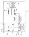
- Fig. 1 is a block diagram which shows a camera 1 including an image blur reduction device according to an embodiment of the present invention.
- the camera 1 is a digital still camera including an optical axis bending system that changes the direction of the optical axis in a photographic optical system.
- the camera 1 includes a lens barrel 2, a control unit 11, a display unit 12, a storage unit 13, an operation unit 14, and so forth.
- the lens barrel 2 includes a prism P which is an optical-axis bending unit that changes the direction of the optical axis, a lens L, an image sensor 3, and so forth.
- the light input to the lens barrel 2 from an unshown subject is deflected by the prism P by 90 degrees.
- the image of the subject is formed on the image sensor 3 by the lens L.
- the lens L includes multiple lenses such as a zoom lens, focus lens, vibration reduction lens, etc.
- Fig. 1 collectively shows these lenses in the form of the lens L for convenience of explanation. Detailed description will be made later regarding the lens barrel 2 with reference to Fig. 2 .
- the image sensor 3 is a photoelectric conversion device such as a CCD, CMOS, or the like, for example.
- the image sensor 3 converts the incident light to the image forming plane into an electric signal.
- the electric signal thus converted is transmitted to the control unit 11 as an image signal.
- the control unit 11 includes an ASIC and so forth, which controls the overall system of the camera 1.
- the control unit 11 Upon reception of an image signal from the image sensor 3, the control unit 11 performs predetermined processing for the image signal thus input.
- the image data After the image data has been subjected to the processing by the control unit 11, and has been converted into JPEG file format as necessary, the image data is stored in the storage unit 13. Furthermore, the image data thus processed by the control unit 11 is displayed on the display unit 12 such as a liquid crystal display or the like provided to the camera 1.
- the storage unit 13 is an external storage medium detachably mounted to the camera 1, for example.
- the operation unit 14 is an operating unit which provides the user operation, including a release button, a zoom button, a cross button that allows various photographic modes to be set, and so forth.
- the control unit 11 upon the user operating the release button of the operation unit 14, the control unit 11 performs opening/closing action of an unshown shutter so as to have the image sensor 3 exposed for a predetermined period of time, thereby capturing an image of the subject.
- the control unit 11 drives an unshown motor so as to move the zoom lens, thereby changing the power of the zoom lens at which to form a subject image on the image sensor 3.
- Voice coil motors (VCM) 130 and 140 are actuators that move the vibration reduction lens group included in the lens L for reducing the image vibration or image blur due to vibration of the camera.
- Position detectors 150 and 160 detect the position of the vibration reduction lens group, and transmits the detection results to the control unit 11.
- the control unit 11 controls and drives the VCMs 130 and 140 based upon the position of the vibration reduction lens group thus detected by the position detectors 150 and 160. Detailed description will be made later regarding vibration reduction control using the VCMs 130 and 140, the position detectors 150 and 160, and the vibration reduction lens group.
- An angular speed detector 15 is a sensor for detecting the motion of the camera 1 occurring due to vibration of the hand-held camera 1 and so forth.
- the angular speed detector 15 includes an angular speed sensor for detecting the rotation (pitching) around the horizontal axis (X axis shown in Fig. 2 ) of the camera 1, and an angular sensor for detecting the rotation (yawing) around the vertical axis (Z axis shown in Fig. 2 ) of the camera 1.
- the angular speed detector 15 detects the angular speeds of the camera 1, and outputs the detected signals to the control unit 11.
- The.control unit 11 computes the tilt angles of the camera 1 based upon the detected signals received from the angular speed detector 15. Then, the control unit 11 calculates the distance and the direction of the movement of the vibration reduction lens group necessary for reducing the vibration based upon the position of the vibration reduction lens group thus detected by the position detectors 150 and 160 and the tilt angles of the camera 1.
- control unit 11 calculates the distance and the direction of the movement of the vibration reduction lens group giving consideration to the change in the optical axis by the optical-axis bending unit, and the difference between the detection directions of the position detectors 150 and 160 and the directions along the XYZ axes.
- the control unit 11 outputs a control signal to the VCMs 130 and 140 based upon the movement parameters thus calculated. Then, the VCMs 130 and 140 moves the vibration reduction lens group according to the control signal. With such an arrangement, even if vibration has occurred at the time of capturing an image, the vibration reduction lens group is moved so as to cancel the vibration, thereby reducing image vibration or image blur occurring in a captured image.
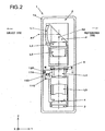
- the lens barrel 2 includes a photographic optical system having a structure in which a first lens group L1, the prism P, a second lens group L2, a third lens group L3, a vibration reduction lens group (fourth lens group) L4, and a fifth lens group L5, are disposed in that order from the subject side. Furthermore, the lens barrel 2 includes the image sensor 3, a low-pass filter 4, and a shutter aperture unit 5, and so forth.
- the first lens group L1 is provided at a position farthest to the subject side in the photographic optical system.
- the prism P optical-axis bending unit
- the prism P is a rectangular prism which provides the total reflection of the light of the subject image output from the first lens group L1, thereby bending the direction of the optical path by 90 degrees.
- the optical axis A1 extends along the horizontal direction with respect to the prism P, while the optical axis A2 extends along the vertical direction with respect to the prism P.
- the term "time of capturing an image by the camera 1 in a normal state" represents the time at which the camera 1 is held level. In this state, the camera 1 is held with the horizontal direction of the camera 1 matching the direction of the optical axis A1, and with the long side of a display monitor (not shown ) of the display unit 12 extending along the horizontal direction.
- the second lens group L2 and other lens groups provided farther toward the image side (the side of the image sensor 3) are serially disposed downstream of the prism P.
- the second lens group L2 is provided on the output side of the prism P.
- the second lens group L2 is provided at a fixed position relative to the prism P.
- the third lens group L3 is provided on the output side of the second lens group L2, and can be moved along the optical axis A2 by an unshown lens driving motor.
- the vibration reduction lens group (fourth lens group) L4 is provided on the output side of the third lens group L3, and forms a part of an image blur reduction device 100. Detailed description will be made later regarding the configuration and functions of the vibration reduction device 100.
- the vibration reduction lens group L4 is an image blur reduction optical system for reducing image blur due to the vibration of the camera 1 by shifting the vibration reduction lens group L4 within a plane orthogonal to the optical axis A2.
- the vibration reduction lens group L4 is constituted of at least one lens.
- the fifth lens group L5 is provided on the output side of the vibration reduction lens group L4, and can be moved along the optical axis A2 by an unshown lens driving motor.
- the image sensor 3 is provided on the output side of the fifth lens group L5, which generates an electric image output signal based upon the light of the subject image formed on the image forming surface by the photographic optical system.
- the low-pass filter (LPF) 4 is provided between the fifth lens group L5 and the image sensor 3, which prevents moire occurring in the image output signal output from the image sensor 3.
- the shutter aperture unit 5 is provided on the input side of the vibration reduction lens group L4, which includes an aperture unit for controlling the light amount of the image passing through the photographic optical system and a shutter unit for adjusting the exposure period of time during which the image sensor 3 is exposed to the light.
- the lens barrel 2 includes the image blur reduction device 100 described below.
- Fig. 3 is a cross-sectional view of the lens barrel 2 taken along line III-III in Fig. 2 .
- the image blur reduction device 100 includes the vibration reduction lens group L4, a fixed frame 110, a vibration frame 120, the voice coil motors 130 and 140, the position detectors 150 and 160, and steel balls 170.
- the fixed frame 110 is a frame provided at a fixed position relative to the optical axis A2.
- the vibration frame 120 is a holding frame for holding the vibration reduction lens group L4 at the central portion thereof.
- the vibration frame 120 is held in a manner that allows it to be moved relatively to the fixed frame 110 within a plane (X-Y plane) orthogonal to the optical axis A2.
- the fixed frame 110 has an opening at a portion that corresponds to the vibration reduction lens group L4, thereby allowing the light flux to pass through the fixed frame 110 via the vibration reduction lens group L4 (see Fig. 2 ).
- each of the fixed frame 110 and the vibration frame 120 is formed in an approximately rectangular form having a greater width along the direction (X direction shown in Fig. 3 ) orthogonal to the optical axes A1 and A2 than the height along the direction (Y direction shown in Fig. 3 ) parallel to the optical axis A1. Furthermore, the fixed frame 110 and the vibration frame 120 have tabs 111 and 121, respectively, each of which is provided to the longer side thereof facing the subject side so as to protrude toward the subject side.
- the voice coil motors (VCM) 130 and 140 are electromagnetic actuators which drive the vibration frame 120 relative to the fixed frame 110 within a plane orthogonal to the optical axis A2.
- the VCMs 130 and 140 are used for known image blur reduction control. With the known image blur reduction control method, the vibration frame 120 is driven by the VCMs 130 and 140 according to the angular speed of the camera 1 detected by the angular speed detector 15, thereby suppressing image blur.
- the VCMs 130 and 140 are disposed distanced from each other along the longitudinal direction of the fixed frame 110 and the vibration frame 120 (X direction).
- each of the driving direction (thrusting direction) D1 along which the VCM 130 drives the vibration frame 120 and the driving direction (thrusting direction) D2 along which the VCM 140 drives the vibration frame 120 are inclined by 45 degrees with respect to the longitudinal direction (X direction).
- the VCMs 130 and 140 are disposed such that the driving directions D1 and D2 orthogonally intersect.
- the phrase "the state in which the vibration frame 120 has been centered on the fixed frame 110" as used here represents the state in which the optical axis of the vibration reduction lens group L4 held by the vibration frame 120 substantially matches the optical axis A2 of the other lens groups as shown in Fig. 3 .
- Each of the VCMs 130 and 140 has a shape having a greater length along the direction orthogonal to the driving direction D1 or D2 than the length along the driving direction D1 or D2.
- the two VCMs 130 and 140 are disposed at positions in line symmetry with respect to the line AL which is parallel to the Y direction and which passes through the optical axis of the vibration reduction lens group L4 as shown in Fig. 3 . With such a layout, the closer to the subject side, the greater the distance between the VCMs 130 and 140 is.
- the vibration reduction lens group L4 is disposed such that the optical axis thereof is positioned between the VCM 130 and the VCM 140.
- the phrase "the region between the VCM 130 and the VCM 140" describes the region surrounded by the line between the point V3 which is the point of the VCM 130 farthest to the subject side and the point V4 which is the point of the VCM 140 farthest to the photographer side, the line between the point V5 which is the point of the VCM 130 farthest to the subject side and the point V6 which is the point of the VCM 140 farthest to the subject side, and the VCM 130 and the VCM 140.
- first driving center line (first thrusting center line) TL1 the line which passes through the center V2 of the VCM 140 and which is parallel to the driving direction D1
- second driving center line (second thrusting center line) TL2 the line which passes through the center V2 of the VCM 140 and which is parallel to the driving direction D2
- the vibration reduction lens group L4 is disposed such that the optical axis thereof is positioned with a predetermined distance from the intersection point O of the first driving center line TL1 and the second driving center line TL2 along the Y axis direction.
- the aforementioned predetermined distance from the intersection point O is determined such that the optical axis of the vibration reduction lens group L4 is positioned closer to at least one of the VCM 130 and the VCM 140 than as to the intersection point O.
- the vibration reduction lens group L4 may be disposed such that the optical axis thereof is positioned with a predetermined distance along the Y-axis direction from the intersection of the first center line and the second center line. Also, the vibration reduction lens group L4 may be disposed offset by a predetermined distance, along any direction that differs from the Y-axis direction, from the intersection of the first center line and the second center line.
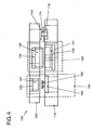
- Fig. 4 is a cross-sectional view taken along line IV-IV in Fig. 3 .
- the VCM 130 includes a coil 131, a magnet 132, yokes 133 and 134 as shown in Fig. 4 .
- the coil 131 is an electric winding fixed to the fixed frame 110 so as to face the vibration frame 120. Furthermore, the coil 131 is formed in an elliptic shape with the long axis extending along the direction orthogonal to the driving direction as shown in Fig. 3 .
- the magnet 132 is a permanent magnet fixed to the vibration frame 120 so as to face the coil 131.
- the yokes 133 and 134 are formed of a magnetic material such as a ferrous metal or the like in the shape of a plate, for example.
- the yoke 133 is disposed on the face of the coil 131 opposite to that facing the magnet 132.
- the yoke 134 is disposed on the face of the magnet 132 opposite to that facing the coil 131.
- VCM 140 has the same structure as that of the aforementioned VCM 130.
- the position detectors 150 and 160 are position sensors for detecting the position of the vibration frame 120 relative to the fixed frame 110 within the plane (X-Y plane) orthogonal to the optical axis A2. Specifically, the position detector 150 detects the position of the vibration reduction lens group L4 along the detection direction D3. On the other hand, the position detector 160 detects the position of the vibration reduction lens group L4 along the detection direction D4.
- the detection direction D3 of the position detector 150 is parallel to the driving direction D2 of the aforementioned VCM 140.
- the position detector 150 is disposed along the line which passes through the optical axis A2 and which is parallel to the detection direction D3.
- the detection direction D4 of the position detector 160 is parallel to the driving direction D1 of the aforementioned VCM 130.
- the position detector 160 is disposed along the line which passes through the optical axis A2 and which is parallel to the detection direction D4.
- a line which extends along the detection direction D3 of the position detector 150 passing through the center of the position detector 150 and a line which extends along the detection direction D4 of the position detector 160 passing through the center of the position detector 160 intersect at the optical axis of the vibration reduction lens group L4.
- the position detectors 150 and 160 are provided near the ends of the fixed frame 110 and the vibration frame 120 on the subject side. With such an arrangement, each of the position detectors 150 and 160 is disposed such that a part thereof is positioned within the aforementioned tabs 111 and 121. Furthermore, each of the position detectors 150 and 160 is disposed such that a part thereof is positioned within a region extending along the X direction between the VCMs 130 and 140. Also, each of the position detectors 150 and 160 may be disposed such that at least a part thereof is positioned between the VCMs 130 and 140.
- the position detector 150 includes a magnet 151, a Hall sensor 152, and yokes 153 and 154.
- the magnet 151 is a permanent magnet fixed to the vibration frame 120 so as to face the fixed frame 110.
- the Hall sensor 152 is provided for detecting change in the magnetic field occurring due to the magnet 151 according to the change in the position of the vibration frame 120 relative to the fixed frame 110.
- the yoke 153 is disposed on the face of the magnet 151 opposite to that facing the Hall sensor 152.
- the yoke 154 is disposed on the face of the Hall sensor 152 opposite to that facing the magnet 151.
- the position detector 160 has the same structure as that of the aforementioned position detector 150.
- the steel balls 170 are provided such that they are held between the fixed frame 110 and the vibration frame 120, which serve as rolling elements. With such an arrangement, the vibration frame 120 is held by the fixed frame 110 in a manner that allows the vibration frame 120 to be moved relative to the fixed frame 110 within a plane orthogonal to the optical axis A2.
- the fixed frame 110 has recesses 112 formed in the shape of a cup on the face thereof that faces the vibration frame 120.
- the bottom of the recess 112 is formed as a smooth surface parallel to the plane orthogonal to the optical axis A2.
- the vibration frame 120 has protrusions 122 that protrude so as to face the respective recesses 112 of the fixed frame 110.
- the surface of each protrusions 122 that faces the corresponding recess 112 is formed as a smooth surface parallel to the plane orthogonal to the optical axis A2.
- the steel balls 170 are provided such that they are held between the bottoms of the recesses 112 and the respective surfaces of the protrusions 122 provided so as to face the recesses 112.
- the steel balls 170 are provided at three positions as indicated by reference numerals 170a, 170b, and 170c in Fig. 3 .
- the steel ball 170a is provided to a region between the position detectors 150 and 160 provided in the tabs 111 and 121 of the fixed frame 110 and the vibration frame 120.
- the steel balls 170b and 170c are provided at positions along the end of the image blur reduction device 100 on the photographer side (opposite to the subject side) and at ends of the fixed frame 110 and the vibration frame 120 in the longitudinal direction (X direction).
- the VCM 130 is disposed between the steel balls 170a and 170b, and the VCM 140 is disposed between the steel balls 170a and 170c.
- the aforementioned embodiment can provide the following operational effects.
- a lens barrel 2A of the camera 1A includes the prism P, the lens L, the image sensor 3, the angular speed detector 15, and so forth, in the same way as in the above-described embodiment.
- the image sensor 3 is held by a movable member 3A, and is configured such that it can be moved within a plane orthogonal to the optical axis of the lens L. Note that with such an arrangement, vibration reduction control is performed by moving the image sensor 3. Accordingly, the lens L does not include the vibration reduction lens group L4.
- Each of actuators 230 and 240 includes a piezo element, for example, which allows the movable member 3A that holds the image sensor 3 to be moved within the plane orthogonal to the optical axis of the lens L.
- Position detectors 250 and 260 detect the position of the image sensor 3 within the plane orthogonal to the optical axis of the lens L.
- a control unit 11A calculates the distance and the direction of the movement of the image sensor 3 based upon the detected value received from the angular speed detector 15 and the detected values received from the position detectors 250 and 260. Then, the control unit 11A transmits control signals to the actuators 230 and 240.
- the layout of the actuators 230 and 240 and the position detectors 250 and 260, which takes the center of the image sensor 3 as the basic position is the same as the layout of the VCMs 130 and 140 and the position detectors 150 and 160 with the optical axis of the vibration reduction lens group L4 as the basic position according to the aforementioned embodiment. That is to say, the center of the image sensor 3 is located in a region between the actuators 230 and 240.
- the center of the image sensor 3 is located at a position with a predetermined distance from the intersection of a first driving line, which is parallel to a first direction along which the actuator 230 moves the image sensor 3 and which passes through the center of the actuator 230, and a second driving line, which is parallel to a second direction along which the actuator 240 moves the image sensor 3 and which passes through the center of the actuator 240.
- the predetermined distance from the intersection is determined such that the center of the image sensor 3 is located at a position closer to the actuators 230 and 240 than as to the intersection.
Claims (8)
- Vorrichtung zur Verminderung der Bildunschärfe, beinhaltend:ein optisches System (L), das ein optisches System zur Verminderung der Bildunschärfe (L4) beinhaltet;ein erstes Antriebsmittel (130) zum Generieren von Schub in eine erste Richtung (D1), um das optische System zur Verminderung der Bildunschärfe (L4) zu bewegen; undein zweites Antriebsmittel (140) zum Generieren von Schub in eine zweite Richtung (D2), die sich von der ersten Richtung unterscheidet, um das optische System zur Verminderung der Bildunschärfe (L4) zu bewegen,wobei sich die optische Achse (A2) des optischen Systems zur Verminderung der Bildunschärfe (L4) zwischen dem ersten Antriebsmittel (130) und dem zweiten Antriebsmittel (140) befindet;sich die optische Achse des optischen Systems zur Verminderung der Bildunschärfe um einen vorbestimmten Abstand von der Überschneidung (0) der ersten Antriebsmittellinie (TL1), die durch die Mitte des ersten Antriebsmittels durchgeht und die parallel zur ersten Richtung ist, und der zweiten Antriebsmittellinie (TL2), die durch die Mitte des zweiten Antriebsmittels durchgeht und die parallel zur zweiten Achse ist, abgesetzt befindet;der vorbestimmte Abstand größer als der Abstand von der optischen Achse des optischen Systems zur Verminderung der Bildunschärfe zu mindestens einem des ersten Antriebsmittels und des zweiten Antriebsmittels ist;das erste Antriebsmittel ein erster Schwingspulenmotor ist, der eine erste Spule und einen ersten Magnet beinhaltet;das zweite Antriebsmittel ein zweiter Schwingspulenmotor ist, der eine zweite Spule und einen zweiten Magnet beinhaltet; unddie Überschneidung (0) der ersten Antriebsmittellinie und der zweiten Antriebsmittellinie außerhalb des optischen Systems zur Verminderung der Bildunschärfe positioniert ist.
- Vorrichtung zur Verminderung der Bildunschärfe gemäß Anspruch 1, wobei:eine längslaufende Richtung des ersten Antriebsmittels (130) und eine längslaufende Richtung des zweiten Antriebsmittels (140) rechtwinklig zur ersten Richtung bzw. zur zweiten Richtung sind, undsich die erste Richtung und die zweite Richtung bei 90 Grad überschneiden.
- Vorrichtung zur Verminderung der Bildunschärfe gemäß Anspruch 2, wobei:das erste Antriebsmittel (130) und das zweite Antriebsmittel (140) auf einer Ebene, rechtwinklig zur optischen Achse (A2) des optischen Systems zur Verminderung der Bildunschärfe (L4) in Liniensymmetrie mit Bezug auf eine vorbestimmte Linie (AL), die durch die optische Achse durchgeht, angeordnet sind.
- Vorrichtung zur Verminderung der Bildunschärfe gemäß einem der Ansprüche 1 bis 3, weiter beinhaltend:ein Halteglied (120), das das optische System zur Verminderung der Bildunschärfe (L4) hält, wobei:das erste Antriebsmittel (130) und das zweite Antriebsmittel (140) das Halteglied (120) innerhalb einer Ebene, rechtwinklig zu einer optischen Achse (A2) des optischen Systems, bewegen, um so das optische System zur Verminderung der Bildunschärfe entlang der ersten Richtung und der zweiten Richtung zu bewegen.
- Vorrichtung zur Verminderung der Bildunschärfe gemäß Anspruch 4, weiter beinhaltend:ein festes Glied (110), das eine Öffnung beinhaltet, durch die ein Lichtstrom durchgeht, um so durch das optische System zur Verminderung der Bildunschärfe (L4) durchzugehen, und das das Halteglied (120) in einer Weise hält, die dem Halteglied erlaubt, innerhalb einer Ebene, rechtwinklig zur optischen Achse (A2) des optischen Systems, bewegt zu werden.
- Vorrichtung zur Verminderung der Bildunschärfe gemäß einem der Ansprüche 1 bis 5, weiter beinhaltend:ein erstes Positionserkennungsmittel (150) zum Erkennen einer Position des optischen Systems zur Verminderung der Bildunschärfe (L4) entlang der ersten Richtung; undein zweites Positionserkennungsmittel (160) zum Erkennen einer Position des optischen Systems zur Verminderung der Bildunschärfe (L4) entlang der zweiten Richtung, wobei:die optische Achse (A2) des optische Systems zur Verminderung der Bildunschärfe mit einer Überschneidung einer ersten Erkennungsmittellinie, die durch eine Mitte des ersten Positionserkennungsmittels geht und die parallel zur ersten Richtung ist, und einer zweiten Erkennungsmittellinie, die durch eine Mitte des zweiten Positionserkennungsmittels geht und die parallel zur zweiten Richtung ist, übereinstimmt.
- Vorrichtung zur Verminderung der Bildunschärfe gemäß Anspruch 6, wobei:mindestens ein Teil des ersten Positionserkennungsmittels (150) und des zweiten Positionserkennungsmittels (160) zwischen dem ersten Antriebsmittel (130) und dem zweiten Antriebsmittel (140) angeordnet ist.
- Kamera beinhaltend:eine Vorrichtung zur Verminderung der Bildunschärfe gemäß einem der Ansprüche 1 bis 7.
Priority Applications (2)
| Application Number | Priority Date | Filing Date | Title |
|---|---|---|---|
| EP15191766.3A EP3001239A1 (de) | 2006-03-07 | 2007-03-06 | Vibrationsverminderungsvorrichtung und kamera |
| EP10185561.7A EP2267512B1 (de) | 2006-03-07 | 2007-03-06 | Vorrichtung zur Verminderung der Bildunschärfe und Kamera |
Applications Claiming Priority (1)
| Application Number | Priority Date | Filing Date | Title |
|---|---|---|---|
| JP2006061132A JP4844177B2 (ja) | 2006-03-07 | 2006-03-07 | ブレ補正装置及びカメラ |
Related Child Applications (3)
| Application Number | Title | Priority Date | Filing Date |
|---|---|---|---|
| EP15191766.3A Division-Into EP3001239A1 (de) | 2006-03-07 | 2007-03-06 | Vibrationsverminderungsvorrichtung und kamera |
| EP15191766.3A Division EP3001239A1 (de) | 2006-03-07 | 2007-03-06 | Vibrationsverminderungsvorrichtung und kamera |
| EP10185561.7A Division-Into EP2267512B1 (de) | 2006-03-07 | 2007-03-06 | Vorrichtung zur Verminderung der Bildunschärfe und Kamera |
Publications (3)
| Publication Number | Publication Date |
|---|---|
| EP1832912A2 EP1832912A2 (de) | 2007-09-12 |
| EP1832912A3 EP1832912A3 (de) | 2007-10-31 |
| EP1832912B1 true EP1832912B1 (de) | 2015-12-23 |
Family
ID=38077202
Family Applications (3)
| Application Number | Title | Priority Date | Filing Date |
|---|---|---|---|
| EP07103623.0A Active EP1832912B1 (de) | 2006-03-07 | 2007-03-06 | Vorrichtung zur Verminderung der Bildunschärfe und Kamera |
| EP10185561.7A Active EP2267512B1 (de) | 2006-03-07 | 2007-03-06 | Vorrichtung zur Verminderung der Bildunschärfe und Kamera |
| EP15191766.3A Withdrawn EP3001239A1 (de) | 2006-03-07 | 2007-03-06 | Vibrationsverminderungsvorrichtung und kamera |
Family Applications After (2)
| Application Number | Title | Priority Date | Filing Date |
|---|---|---|---|
| EP10185561.7A Active EP2267512B1 (de) | 2006-03-07 | 2007-03-06 | Vorrichtung zur Verminderung der Bildunschärfe und Kamera |
| EP15191766.3A Withdrawn EP3001239A1 (de) | 2006-03-07 | 2007-03-06 | Vibrationsverminderungsvorrichtung und kamera |
Country Status (3)
| Country | Link |
|---|---|
| US (1) | US8295694B2 (de) |
| EP (3) | EP1832912B1 (de) |
| JP (1) | JP4844177B2 (de) |
Families Citing this family (30)
| Publication number | Priority date | Publication date | Assignee | Title |
|---|---|---|---|---|
| JP5003008B2 (ja) * | 2006-04-17 | 2012-08-15 | コニカミノルタアドバンストレイヤー株式会社 | 手振れ補正装置、レンズユニットおよび撮像装置 |
| KR101404843B1 (ko) * | 2006-06-22 | 2014-06-09 | 가부시키가이샤 니콘 | 위치 결정 장치, 떨림 보정 장치 및 전자 기기 |
| JP5109450B2 (ja) * | 2007-04-09 | 2012-12-26 | 株式会社ニコン | ブレ補正装置及び光学機器 |
| US20080297901A1 (en) * | 2007-05-29 | 2008-12-04 | Nikon Corporation | Zoom lens system, optical apparatus, and method for forming an image |
| KR101378212B1 (ko) * | 2007-07-20 | 2014-04-14 | 삼성전자주식회사 | 모바일 기기용 카메라 모듈에서 진동으로 인한 노이즈를제어하는 장치 및 방법 |
| JP2009069588A (ja) * | 2007-09-14 | 2009-04-02 | Konica Minolta Opto Inc | 光学ユニットおよび撮像装置 |
| JP4991497B2 (ja) | 2007-11-28 | 2012-08-01 | 三星電子株式会社 | 像ぶれ補正装置 |
| US8159540B2 (en) * | 2007-11-28 | 2012-04-17 | Semiconductor Components Industries, Llc | Semiconductor device and imaging capturing apparatus |
| WO2009093635A1 (ja) * | 2008-01-22 | 2009-07-30 | Nikon Corporation | レンズ鏡筒、レンズ鏡筒の調整方法、レンズ鏡筒の製造方法及び撮像装置 |
| CN102165367B (zh) * | 2008-09-29 | 2014-02-12 | 日本电产科宝株式会社 | 像抖动修正装置、摄像透镜单元和相机单元 |
| GB0918453D0 (en) | 2009-10-21 | 2009-12-09 | Selexsensors And Airborne Syst | Imaging device |
| JP5269143B2 (ja) * | 2010-07-16 | 2013-08-21 | キヤノン株式会社 | 像ブレ補正装置及びその制御方法及び撮像装置 |
| US9485495B2 (en) | 2010-08-09 | 2016-11-01 | Qualcomm Incorporated | Autofocus for stereo images |
| US9172856B2 (en) * | 2011-03-29 | 2015-10-27 | Microsoft Technology Licensing, Llc | Folded imaging path camera |
| US9438889B2 (en) | 2011-09-21 | 2016-09-06 | Qualcomm Incorporated | System and method for improving methods of manufacturing stereoscopic image sensors |
| US9398264B2 (en) | 2012-10-19 | 2016-07-19 | Qualcomm Incorporated | Multi-camera system using folded optics |
| US10178373B2 (en) | 2013-08-16 | 2019-01-08 | Qualcomm Incorporated | Stereo yaw correction using autofocus feedback |
| US9383550B2 (en) | 2014-04-04 | 2016-07-05 | Qualcomm Incorporated | Auto-focus in low-profile folded optics multi-camera system |
| US9374516B2 (en) | 2014-04-04 | 2016-06-21 | Qualcomm Incorporated | Auto-focus in low-profile folded optics multi-camera system |
| US10013764B2 (en) | 2014-06-19 | 2018-07-03 | Qualcomm Incorporated | Local adaptive histogram equalization |
| US9549107B2 (en) * | 2014-06-20 | 2017-01-17 | Qualcomm Incorporated | Autofocus for folded optic array cameras |
| US9294672B2 (en) | 2014-06-20 | 2016-03-22 | Qualcomm Incorporated | Multi-camera system using folded optics free from parallax and tilt artifacts |
| US9541740B2 (en) | 2014-06-20 | 2017-01-10 | Qualcomm Incorporated | Folded optic array camera using refractive prisms |
| US9819863B2 (en) | 2014-06-20 | 2017-11-14 | Qualcomm Incorporated | Wide field of view array camera for hemispheric and spherical imaging |
| US9386222B2 (en) | 2014-06-20 | 2016-07-05 | Qualcomm Incorporated | Multi-camera system using folded optics free from parallax artifacts |
| US9509891B2 (en) | 2014-10-21 | 2016-11-29 | Microsoft Technology Licensing, Llc | Controlling focus lens assembly |
| US9832381B2 (en) | 2014-10-31 | 2017-11-28 | Qualcomm Incorporated | Optical image stabilization for thin cameras |
| JP6611498B2 (ja) | 2015-07-17 | 2019-11-27 | オリンパス株式会社 | 振れ補正装置 |
| CN108333791B (zh) * | 2018-04-28 | 2023-07-14 | 江西星星科技股份有限公司 | 一种摄像头防抖结构 |
| KR102258604B1 (ko) * | 2019-09-10 | 2021-05-31 | 삼성전기주식회사 | 촬상 광학계 |
Family Cites Families (37)
| Publication number | Priority date | Publication date | Assignee | Title |
|---|---|---|---|---|
| JPH0281009A (ja) * | 1988-09-19 | 1990-03-22 | Canon Inc | 光学素子保持枠の支持構造 |
| US5266988A (en) | 1989-12-18 | 1993-11-30 | Canon Kabushiki Kaisha | Image shake suppressing device for camera |
| JP3661229B2 (ja) * | 1994-06-28 | 2005-06-15 | 株式会社ニコン | 防振カメラ |
| JPH103101A (ja) | 1996-06-18 | 1998-01-06 | Nikon Corp | ブレ補正装置 |
| US5854947A (en) | 1996-06-18 | 1998-12-29 | Nikon Corporation | Vibration reducing apparatus |
| JP3713818B2 (ja) | 1996-06-18 | 2005-11-09 | 株式会社ニコン | 像ブレ補正装置 |
| JP3858308B2 (ja) | 1996-09-10 | 2006-12-13 | 株式会社ニコン | ブレ補正装置、ブレ補正装置を有するレンズ鏡筒及びブレ補正装置を有するカメラ |
| JPH10186431A (ja) | 1996-12-26 | 1998-07-14 | Nikon Corp | ブレ補正装置 |
| JPH10228044A (ja) | 1997-02-17 | 1998-08-25 | Nikon Corp | ブレ補正装置と切替装置 |
| JP3864483B2 (ja) | 1997-03-11 | 2006-12-27 | 株式会社ニコン | レンズ鏡筒 |
| JP3809691B2 (ja) | 1997-03-11 | 2006-08-16 | 株式会社ニコン | ブレ補正装置及びレンズ鏡筒 |
| US5926656A (en) | 1997-03-11 | 1999-07-20 | Nikon Corporation | Vibration reducing apparatus and lens barrel |
| JPH10254016A (ja) | 1997-03-14 | 1998-09-25 | Nikon Corp | ブレ補正装置 |
| US5905917A (en) | 1997-03-14 | 1999-05-18 | Nikon Corporation | Vibration reduction device |
| JPH10254009A (ja) | 1997-03-14 | 1998-09-25 | Nikon Corp | ブレ補正装置 |
| US6154611A (en) | 1998-05-18 | 2000-11-28 | Canon Kabushiki Kaisha | Image-shake compensation apparatus |
| JP2000330153A (ja) * | 1999-05-19 | 2000-11-30 | Canon Inc | 像振れ補正装置 |
| JP2001201777A (ja) | 2000-01-14 | 2001-07-27 | Minolta Co Ltd | ぶれ補正装置及び該ぶれ補正装置を含む光学機器 |
| JP3969927B2 (ja) * | 2000-04-06 | 2007-09-05 | キヤノン株式会社 | レンズ鏡筒、撮影装置及び観察装置 |
| JP2001305434A (ja) | 2000-04-18 | 2001-10-31 | Asahi Optical Co Ltd | 像振れ補正装置 |
| JP3551932B2 (ja) * | 2001-03-30 | 2004-08-11 | ミノルタ株式会社 | 測距装置及びそれを用いた撮像装置 |
| JP2003057707A (ja) | 2001-08-08 | 2003-02-26 | Matsushita Electric Ind Co Ltd | 像ぶれ補正装置 |
| JP2003075881A (ja) | 2001-08-31 | 2003-03-12 | Pentax Corp | 像振れ補正装置 |
| JP3907451B2 (ja) * | 2001-11-19 | 2007-04-18 | 松下電器産業株式会社 | 像振れ補正装置およびその製造方法 |
| JP2003255422A (ja) | 2002-03-04 | 2003-09-10 | Canon Inc | 補正光学系加振装置 |
| JP2003322889A (ja) * | 2002-05-07 | 2003-11-14 | Sigma Corp | 手振れ補正装置 |
| JP4253177B2 (ja) * | 2002-11-26 | 2009-04-08 | 株式会社シグマ | 画像振れ防止装置 |
| JP2005077886A (ja) * | 2003-09-02 | 2005-03-24 | Canon Inc | 撮影装置 |
| JP2005084655A (ja) | 2003-09-11 | 2005-03-31 | Olympus Corp | 屈曲光学系用レンズ筐体 |
| JP2005217993A (ja) * | 2004-01-30 | 2005-08-11 | Canon Inc | 撮影装置 |
| JP2005221603A (ja) | 2004-02-04 | 2005-08-18 | Matsushita Electric Ind Co Ltd | 像ブレ補正装置 |
| US7742076B2 (en) * | 2004-05-25 | 2010-06-22 | Hoya Corporation | Image-capturing apparatus and camera-shake compensation mechanism |
| JP2005352125A (ja) | 2004-06-10 | 2005-12-22 | Nikon Corp | ブレ補正装置 |
| US7710459B2 (en) * | 2004-07-21 | 2010-05-04 | Hewlett-Packard Development Company, L.P. | Ferrofluid suspension for image stabilization |
| JP2006243701A (ja) | 2005-02-07 | 2006-09-14 | Fuji Photo Film Co Ltd | カメラ及びレンズ装置 |
| JP2006267752A (ja) * | 2005-03-25 | 2006-10-05 | Canon Inc | 像振れ補正装置及び光学機器 |
| JP4789655B2 (ja) * | 2006-03-03 | 2011-10-12 | キヤノン株式会社 | 振れ補正装置、レンズ鏡筒および光学機器 |
-
2006
- 2006-03-07 JP JP2006061132A patent/JP4844177B2/ja active Active
-
2007
- 2007-03-06 EP EP07103623.0A patent/EP1832912B1/de active Active
- 2007-03-06 EP EP10185561.7A patent/EP2267512B1/de active Active
- 2007-03-06 US US11/714,138 patent/US8295694B2/en active Active
- 2007-03-06 EP EP15191766.3A patent/EP3001239A1/de not_active Withdrawn
Also Published As
| Publication number | Publication date |
|---|---|
| JP4844177B2 (ja) | 2011-12-28 |
| EP2267512B1 (de) | 2013-11-06 |
| EP1832912A2 (de) | 2007-09-12 |
| US8295694B2 (en) | 2012-10-23 |
| EP3001239A1 (de) | 2016-03-30 |
| EP1832912A3 (de) | 2007-10-31 |
| JP2007240736A (ja) | 2007-09-20 |
| EP2267512A3 (de) | 2011-05-18 |
| US20070212046A1 (en) | 2007-09-13 |
| EP2267512A2 (de) | 2010-12-29 |
Similar Documents
| Publication | Publication Date | Title |
|---|---|---|
| EP1832912B1 (de) | Vorrichtung zur Verminderung der Bildunschärfe und Kamera | |
| KR101404843B1 (ko) | 위치 결정 장치, 떨림 보정 장치 및 전자 기기 | |
| EP2141539B1 (de) | Vorrichtung zur korrektur von unschärfe und optisches gerät | |
| JP4626780B2 (ja) | カメラの手振れ補正装置 | |
| JP4332583B2 (ja) | レンズ鏡筒およびこれを備えた撮像装置 | |
| CN101995730B (zh) | 光学元件驱动装置以及摄像装置 | |
| JP4830512B2 (ja) | レンズ鏡筒及びカメラ | |
| US7460775B2 (en) | Optical apparatus including efficiently arranged shake correction means | |
| JP4888129B2 (ja) | レンズ鏡筒およびデジタルカメラ | |
| JP5693163B2 (ja) | 振れ補正装置、レンズ鏡筒、及び光学機器 | |
| EP2715444B1 (de) | Bildgebungsvorrichtung | |
| JP2007264396A (ja) | カメラシステム | |
| JP4630467B2 (ja) | 光学装置および撮影装置 | |
| EP3690543B1 (de) | Antriebsvorrichtung, bildunschärfekorrekturvorrichtung und bildaufnahmeeinrichtung mit bildunschärfekorrekturvorrichtung | |
| JP2010026172A (ja) | レンズ鏡筒、レンズ鏡筒の調整方法、光学装置、および光学装置の調整方法 | |
| JP2008076612A (ja) | ブレ補正装置及び光学機器 | |
| JP2010276842A (ja) | 像振れ補正装置 | |
| JP2009175240A (ja) | 光学装置およびその調整方法 | |
| JP2009175241A (ja) | 光学装置およびその調整方法 | |
| JP2009092888A (ja) | 光学機器 | |
| JP2008026882A (ja) | 位置決め装置、ブレ補正装置、電子機器、及び、位置決め装置の製造方法 | |
| JP2010271584A (ja) | 振れ補正装置を有する光学機器 | |
| JP4618004B2 (ja) | 撮像装置 | |
| JP2014228622A (ja) | ブレ補正装置、レンズ鏡筒および撮影装置 | |
| JP2009229551A (ja) | 光学装置およびカメラ |
Legal Events
| Date | Code | Title | Description |
|---|---|---|---|
| PUAI | Public reference made under article 153(3) epc to a published international application that has entered the european phase |
Free format text: ORIGINAL CODE: 0009012 |
|
| AK | Designated contracting states |
Kind code of ref document: A2 Designated state(s): AT BE BG CH CY CZ DE DK EE ES FI FR GB GR HU IE IS IT LI LT LU LV MC MT NL PL PT RO SE SI SK TR |
|
| AX | Request for extension of the european patent |
Extension state: AL BA HR MK YU |
|
| PUAL | Search report despatched |
Free format text: ORIGINAL CODE: 0009013 |
|
| AK | Designated contracting states |
Kind code of ref document: A3 Designated state(s): AT BE BG CH CY CZ DE DK EE ES FI FR GB GR HU IE IS IT LI LT LU LV MC MT NL PL PT RO SE SI SK TR |
|
| AX | Request for extension of the european patent |
Extension state: AL BA HR MK YU |
|
| RIC1 | Information provided on ipc code assigned before grant |
Ipc: H04N 5/232 20060101ALI20070926BHEP Ipc: G02B 27/64 20060101AFI20070611BHEP Ipc: H04N 5/225 20060101ALI20070926BHEP |
|
| 17P | Request for examination filed |
Effective date: 20080423 |
|
| 17Q | First examination report despatched |
Effective date: 20080521 |
|
| AKX | Designation fees paid |
Designated state(s): DE FR GB |
|
| RAP1 | Party data changed (applicant data changed or rights of an application transferred) |
Owner name: NIKON CORPORATION |
|
| RIC1 | Information provided on ipc code assigned before grant |
Ipc: H04N 5/225 20060101ALI20130403BHEP Ipc: G03B 5/00 20060101ALI20130403BHEP Ipc: G03B 17/17 20060101ALI20130403BHEP Ipc: G02B 27/64 20060101AFI20130403BHEP Ipc: H04N 5/232 20060101ALI20130403BHEP |
|
| GRAP | Despatch of communication of intention to grant a patent |
Free format text: ORIGINAL CODE: EPIDOSNIGR1 |
|
| RIN1 | Information on inventor provided before grant (corrected) |
Inventor name: SOGOH, CHIE Inventor name: OMI, JUNICHI |
|
| INTG | Intention to grant announced |
Effective date: 20150618 |
|
| RAP1 | Party data changed (applicant data changed or rights of an application transferred) |
Owner name: NIKON CORPORATION |
|
| GRAS | Grant fee paid |
Free format text: ORIGINAL CODE: EPIDOSNIGR3 |
|
| GRAA | (expected) grant |
Free format text: ORIGINAL CODE: 0009210 |
|
| AK | Designated contracting states |
Kind code of ref document: B1 Designated state(s): DE FR GB |
|
| REG | Reference to a national code |
Ref country code: GB Ref legal event code: FG4D |
|
| REG | Reference to a national code |
Ref country code: DE Ref legal event code: R096 Ref document number: 602007044258 Country of ref document: DE |
|
| REG | Reference to a national code |
Ref country code: FR Ref legal event code: PLFP Year of fee payment: 10 |
|
| REG | Reference to a national code |
Ref country code: DE Ref legal event code: R097 Ref document number: 602007044258 Country of ref document: DE |
|
| PLBE | No opposition filed within time limit |
Free format text: ORIGINAL CODE: 0009261 |
|
| STAA | Information on the status of an ep patent application or granted ep patent |
Free format text: STATUS: NO OPPOSITION FILED WITHIN TIME LIMIT |
|
| 26N | No opposition filed |
Effective date: 20160926 |
|
| REG | Reference to a national code |
Ref country code: FR Ref legal event code: PLFP Year of fee payment: 11 |
|
| REG | Reference to a national code |
Ref country code: FR Ref legal event code: PLFP Year of fee payment: 12 |
|
| REG | Reference to a national code |
Ref country code: DE Ref legal event code: R082 Ref document number: 602007044258 Country of ref document: DE Representative=s name: VENNER SHIPLEY GERMANY LLP, DE Ref country code: DE Ref legal event code: R082 Ref document number: 602007044258 Country of ref document: DE Representative=s name: VENNER SHIPLEY LLP, DE |
|
| PGFP | Annual fee paid to national office [announced via postgrant information from national office to epo] |
Ref country code: FR Payment date: 20230208 Year of fee payment: 17 |
|
| PGFP | Annual fee paid to national office [announced via postgrant information from national office to epo] |
Ref country code: GB Payment date: 20230202 Year of fee payment: 17 Ref country code: DE Payment date: 20230131 Year of fee payment: 17 |
|
| P01 | Opt-out of the competence of the unified patent court (upc) registered |
Effective date: 20230517 |