EP1830077A1 - Verfahren zur herstellung einer verbindungsstange mit lager und verbindungsstange mit lager - Google Patents
Verfahren zur herstellung einer verbindungsstange mit lager und verbindungsstange mit lager Download PDFInfo
- Publication number
- EP1830077A1 EP1830077A1 EP05811477A EP05811477A EP1830077A1 EP 1830077 A1 EP1830077 A1 EP 1830077A1 EP 05811477 A EP05811477 A EP 05811477A EP 05811477 A EP05811477 A EP 05811477A EP 1830077 A1 EP1830077 A1 EP 1830077A1
- Authority
- EP
- European Patent Office
- Prior art keywords
- bearing metal
- connecting rod
- bearing
- rotary pressing
- cylindrical
- Prior art date
- Legal status (The legal status is an assumption and is not a legal conclusion. Google has not performed a legal analysis and makes no representation as to the accuracy of the status listed.)
- Withdrawn
Links
Images


Classifications
-
- B—PERFORMING OPERATIONS; TRANSPORTING
- B23—MACHINE TOOLS; METAL-WORKING NOT OTHERWISE PROVIDED FOR
- B23P—METAL-WORKING NOT OTHERWISE PROVIDED FOR; COMBINED OPERATIONS; UNIVERSAL MACHINE TOOLS
- B23P15/00—Making specific metal objects by operations not covered by a single other subclass or a group in this subclass
-
- B—PERFORMING OPERATIONS; TRANSPORTING
- B21—MECHANICAL METAL-WORKING WITHOUT ESSENTIALLY REMOVING MATERIAL; PUNCHING METAL
- B21J—FORGING; HAMMERING; PRESSING METAL; RIVETING; FORGE FURNACES
- B21J5/00—Methods for forging, hammering, or pressing; Special equipment or accessories therefor
- B21J5/06—Methods for forging, hammering, or pressing; Special equipment or accessories therefor for performing particular operations
- B21J5/063—Friction heat forging
-
- B—PERFORMING OPERATIONS; TRANSPORTING
- B23—MACHINE TOOLS; METAL-WORKING NOT OTHERWISE PROVIDED FOR
- B23K—SOLDERING OR UNSOLDERING; WELDING; CLADDING OR PLATING BY SOLDERING OR WELDING; CUTTING BY APPLYING HEAT LOCALLY, e.g. FLAME CUTTING; WORKING BY LASER BEAM
- B23K20/00—Non-electric welding by applying impact or other pressure, with or without the application of heat, e.g. cladding or plating
- B23K20/12—Non-electric welding by applying impact or other pressure, with or without the application of heat, e.g. cladding or plating the heat being generated by friction; Friction welding
- B23K20/122—Non-electric welding by applying impact or other pressure, with or without the application of heat, e.g. cladding or plating the heat being generated by friction; Friction welding using a non-consumable tool, e.g. friction stir welding
- B23K20/1225—Particular aspects of welding with a non-consumable tool
-
- B—PERFORMING OPERATIONS; TRANSPORTING
- B23—MACHINE TOOLS; METAL-WORKING NOT OTHERWISE PROVIDED FOR
- B23K—SOLDERING OR UNSOLDERING; WELDING; CLADDING OR PLATING BY SOLDERING OR WELDING; CUTTING BY APPLYING HEAT LOCALLY, e.g. FLAME CUTTING; WORKING BY LASER BEAM
- B23K20/00—Non-electric welding by applying impact or other pressure, with or without the application of heat, e.g. cladding or plating
- B23K20/12—Non-electric welding by applying impact or other pressure, with or without the application of heat, e.g. cladding or plating the heat being generated by friction; Friction welding
- B23K20/129—Non-electric welding by applying impact or other pressure, with or without the application of heat, e.g. cladding or plating the heat being generated by friction; Friction welding specially adapted for particular articles or workpieces
- B23K20/1295—Welding studs
-
- F—MECHANICAL ENGINEERING; LIGHTING; HEATING; WEAPONS; BLASTING
- F16—ENGINEERING ELEMENTS AND UNITS; GENERAL MEASURES FOR PRODUCING AND MAINTAINING EFFECTIVE FUNCTIONING OF MACHINES OR INSTALLATIONS; THERMAL INSULATION IN GENERAL
- F16C—SHAFTS; FLEXIBLE SHAFTS; ELEMENTS OR CRANKSHAFT MECHANISMS; ROTARY BODIES OTHER THAN GEARING ELEMENTS; BEARINGS
- F16C33/00—Parts of bearings; Special methods for making bearings or parts thereof
- F16C33/02—Parts of sliding-contact bearings
- F16C33/04—Brasses; Bushes; Linings
- F16C33/06—Sliding surface mainly made of metal
- F16C33/08—Attachment of brasses, bushes or linings to the bearing housing
-
- F—MECHANICAL ENGINEERING; LIGHTING; HEATING; WEAPONS; BLASTING
- F16—ENGINEERING ELEMENTS AND UNITS; GENERAL MEASURES FOR PRODUCING AND MAINTAINING EFFECTIVE FUNCTIONING OF MACHINES OR INSTALLATIONS; THERMAL INSULATION IN GENERAL
- F16C—SHAFTS; FLEXIBLE SHAFTS; ELEMENTS OR CRANKSHAFT MECHANISMS; ROTARY BODIES OTHER THAN GEARING ELEMENTS; BEARINGS
- F16C33/00—Parts of bearings; Special methods for making bearings or parts thereof
- F16C33/02—Parts of sliding-contact bearings
- F16C33/04—Brasses; Bushes; Linings
- F16C33/06—Sliding surface mainly made of metal
- F16C33/14—Special methods of manufacture; Running-in
-
- F—MECHANICAL ENGINEERING; LIGHTING; HEATING; WEAPONS; BLASTING
- F16—ENGINEERING ELEMENTS AND UNITS; GENERAL MEASURES FOR PRODUCING AND MAINTAINING EFFECTIVE FUNCTIONING OF MACHINES OR INSTALLATIONS; THERMAL INSULATION IN GENERAL
- F16C—SHAFTS; FLEXIBLE SHAFTS; ELEMENTS OR CRANKSHAFT MECHANISMS; ROTARY BODIES OTHER THAN GEARING ELEMENTS; BEARINGS
- F16C9/00—Bearings for crankshafts or connecting-rods; Attachment of connecting-rods
- F16C9/04—Connecting-rod bearings; Attachments thereof
-
- F—MECHANICAL ENGINEERING; LIGHTING; HEATING; WEAPONS; BLASTING
- F16—ENGINEERING ELEMENTS AND UNITS; GENERAL MEASURES FOR PRODUCING AND MAINTAINING EFFECTIVE FUNCTIONING OF MACHINES OR INSTALLATIONS; THERMAL INSULATION IN GENERAL
- F16J—PISTONS; CYLINDERS; SEALINGS
- F16J7/00—Piston-rods
-
- B—PERFORMING OPERATIONS; TRANSPORTING
- B23—MACHINE TOOLS; METAL-WORKING NOT OTHERWISE PROVIDED FOR
- B23K—SOLDERING OR UNSOLDERING; WELDING; CLADDING OR PLATING BY SOLDERING OR WELDING; CUTTING BY APPLYING HEAT LOCALLY, e.g. FLAME CUTTING; WORKING BY LASER BEAM
- B23K2101/00—Articles made by soldering, welding or cutting
- B23K2101/006—Vehicles
-
- B—PERFORMING OPERATIONS; TRANSPORTING
- B23—MACHINE TOOLS; METAL-WORKING NOT OTHERWISE PROVIDED FOR
- B23K—SOLDERING OR UNSOLDERING; WELDING; CLADDING OR PLATING BY SOLDERING OR WELDING; CUTTING BY APPLYING HEAT LOCALLY, e.g. FLAME CUTTING; WORKING BY LASER BEAM
- B23K2103/00—Materials to be soldered, welded or cut
- B23K2103/16—Composite materials, e.g. fibre reinforced
-
- B—PERFORMING OPERATIONS; TRANSPORTING
- B23—MACHINE TOOLS; METAL-WORKING NOT OTHERWISE PROVIDED FOR
- B23P—METAL-WORKING NOT OTHERWISE PROVIDED FOR; COMBINED OPERATIONS; UNIVERSAL MACHINE TOOLS
- B23P2700/00—Indexing scheme relating to the articles being treated, e.g. manufactured, repaired, assembled, connected or other operations covered in the subgroups
- B23P2700/04—Connecting rods
-
- F—MECHANICAL ENGINEERING; LIGHTING; HEATING; WEAPONS; BLASTING
- F16—ENGINEERING ELEMENTS AND UNITS; GENERAL MEASURES FOR PRODUCING AND MAINTAINING EFFECTIVE FUNCTIONING OF MACHINES OR INSTALLATIONS; THERMAL INSULATION IN GENERAL
- F16C—SHAFTS; FLEXIBLE SHAFTS; ELEMENTS OR CRANKSHAFT MECHANISMS; ROTARY BODIES OTHER THAN GEARING ELEMENTS; BEARINGS
- F16C17/00—Sliding-contact bearings for exclusively rotary movement
- F16C17/02—Sliding-contact bearings for exclusively rotary movement for radial load only
- F16C17/022—Sliding-contact bearings for exclusively rotary movement for radial load only with a pair of essentially semicircular bearing sleeves
-
- F—MECHANICAL ENGINEERING; LIGHTING; HEATING; WEAPONS; BLASTING
- F16—ENGINEERING ELEMENTS AND UNITS; GENERAL MEASURES FOR PRODUCING AND MAINTAINING EFFECTIVE FUNCTIONING OF MACHINES OR INSTALLATIONS; THERMAL INSULATION IN GENERAL
- F16C—SHAFTS; FLEXIBLE SHAFTS; ELEMENTS OR CRANKSHAFT MECHANISMS; ROTARY BODIES OTHER THAN GEARING ELEMENTS; BEARINGS
- F16C2226/00—Joining parts; Fastening; Assembling or mounting parts
- F16C2226/10—Force connections, e.g. clamping
- F16C2226/12—Force connections, e.g. clamping by press-fit, e.g. plug-in
-
- F—MECHANICAL ENGINEERING; LIGHTING; HEATING; WEAPONS; BLASTING
- F16—ENGINEERING ELEMENTS AND UNITS; GENERAL MEASURES FOR PRODUCING AND MAINTAINING EFFECTIVE FUNCTIONING OF MACHINES OR INSTALLATIONS; THERMAL INSULATION IN GENERAL
- F16C—SHAFTS; FLEXIBLE SHAFTS; ELEMENTS OR CRANKSHAFT MECHANISMS; ROTARY BODIES OTHER THAN GEARING ELEMENTS; BEARINGS
- F16C2226/00—Joining parts; Fastening; Assembling or mounting parts
- F16C2226/50—Positive connections
- F16C2226/60—Positive connections with threaded parts, e.g. bolt and nut connections
-
- F—MECHANICAL ENGINEERING; LIGHTING; HEATING; WEAPONS; BLASTING
- F16—ENGINEERING ELEMENTS AND UNITS; GENERAL MEASURES FOR PRODUCING AND MAINTAINING EFFECTIVE FUNCTIONING OF MACHINES OR INSTALLATIONS; THERMAL INSULATION IN GENERAL
- F16C—SHAFTS; FLEXIBLE SHAFTS; ELEMENTS OR CRANKSHAFT MECHANISMS; ROTARY BODIES OTHER THAN GEARING ELEMENTS; BEARINGS
- F16C2360/00—Engines or pumps
- F16C2360/22—Internal combustion engines
-
- Y—GENERAL TAGGING OF NEW TECHNOLOGICAL DEVELOPMENTS; GENERAL TAGGING OF CROSS-SECTIONAL TECHNOLOGIES SPANNING OVER SEVERAL SECTIONS OF THE IPC; TECHNICAL SUBJECTS COVERED BY FORMER USPC CROSS-REFERENCE ART COLLECTIONS [XRACs] AND DIGESTS
- Y10—TECHNICAL SUBJECTS COVERED BY FORMER USPC
- Y10T—TECHNICAL SUBJECTS COVERED BY FORMER US CLASSIFICATION
- Y10T29/00—Metal working
- Y10T29/49—Method of mechanical manufacture
- Y10T29/49229—Prime mover or fluid pump making
- Y10T29/49288—Connecting rod making
- Y10T29/4929—Connecting rod making including metallurgical bonding
-
- Y—GENERAL TAGGING OF NEW TECHNOLOGICAL DEVELOPMENTS; GENERAL TAGGING OF CROSS-SECTIONAL TECHNOLOGIES SPANNING OVER SEVERAL SECTIONS OF THE IPC; TECHNICAL SUBJECTS COVERED BY FORMER USPC CROSS-REFERENCE ART COLLECTIONS [XRACs] AND DIGESTS
- Y10—TECHNICAL SUBJECTS COVERED BY FORMER USPC
- Y10T—TECHNICAL SUBJECTS COVERED BY FORMER US CLASSIFICATION
- Y10T29/00—Metal working
- Y10T29/49—Method of mechanical manufacture
- Y10T29/49229—Prime mover or fluid pump making
- Y10T29/49288—Connecting rod making
- Y10T29/49291—Connecting rod making including metal forging or die shaping
-
- Y—GENERAL TAGGING OF NEW TECHNOLOGICAL DEVELOPMENTS; GENERAL TAGGING OF CROSS-SECTIONAL TECHNOLOGIES SPANNING OVER SEVERAL SECTIONS OF THE IPC; TECHNICAL SUBJECTS COVERED BY FORMER USPC CROSS-REFERENCE ART COLLECTIONS [XRACs] AND DIGESTS
- Y10—TECHNICAL SUBJECTS COVERED BY FORMER USPC
- Y10T—TECHNICAL SUBJECTS COVERED BY FORMER US CLASSIFICATION
- Y10T74/00—Machine element or mechanism
- Y10T74/21—Elements
- Y10T74/2142—Pitmans and connecting rods
- Y10T74/216—Bearings, adjustable
Definitions
- the present invention relates to a method of producing a connecting rod with a bearing or bearings, and also relates to a connecting rod with a bearing or bearings.
- a connecting rod that connects a piston, and a crank shaft, of an engine of a vehicle to each other includes a large end portion on the side of the crank shaft, a small end portion on the side of the piston, and a rod portion located between the two end portions.
- the small end portion has a circular fitting hole (i.e., a small end hole) in which a piston pin rotatably fits for connection; and the large end portion has a fitting hole (i.e., a large end hole) in which a crank pin rotatably fits for connection.
- a con rod bearing that has, as a whole, a cylindrical shape is assembled with an inner surface of each of the respective fitting holes of the large and small end portions of the connecting rod, and the crank pin and the piston pin rotatably fit, for connection, in the respective fitting holes via the respective con rod bearings.
- the above-mentioned con rod bearings are beforehand produced separately from the connecting rod, and then are assembled with the respective inner surfaces of the two fitting holes. In this state, the large and small end portions of the connecting rod are connected to the crank pin and the piston pin, respectively, via the respective con rod bearings.
- Each con rod bearing is produced by joining a bearing metal (i.e., an alloy) having a thickness of about 0.3 mm, to a thin plate that is a so-called back metal and is provided by a cold-finished hoop having a thickness of about 1.5 mm. That is, the production of each con rod bearing needs complicated steps including (1) a step of casting the bearing metal, (2) a step of working the bearing metal into a thin plate, (3) a step of making the back metal and the bearing metal into a clad, and (4) a step of machining the clad. Thus, the production of each con rod bearing needs much labor, time and cost. In addition, when the con rod bearings are assembled with the connecting rod, high accuracy is required. Thus, the con rod bearings need to be handled with care.
- a bearing metal i.e., an alloy
- the con rod bearings when the con rod bearings are assembled with the connecting rod, foreign matters may enter clearances therebetween, or the problem of accuracy of those clearances may occur. Thus, the assembling of the con rod bearings involves difficulty and care. Moreover, there is another problem that the con rod bearings may be damaged due to seizer, fatigue, rotation with the pins, or fretting (i.e., a phenomenon that small vibrations occur, the outer diameters of the con rod bearings and/or the inner surfaces of the fitting holes of the connecting rod are worn, and the bearings are damaged by the power produced by the wearing).
- a spraying gun cannot be inserted into the fitting hole (i.e., the small end hole) of the small end portion of the connecting rod and accordingly cannot help spaying the bearing metal material in an oblique direction, which leads to lowering the bonding strength of the bearing metal layers and even causing peeling or breaking of the same.
- Patent Document 1 discloses an invention related to a slide-bearing structure.
- a con rod bearing is constituted by a back metal and a bearing metal, and an outer circumferential surface of the back metal is subjected to, e.g., a shot peening so as to improve a degree of hardness thereof and reduce, e.g., wearing of the con rod bearing due to fretting.
- the con rod bearings are produced, in advance, separately from the connecting rod, and then are assembled with the connecting rod.
- the prior invention differs from the present invention.
- Patent Document 2 discloses an invention related to a method of producing a connecting rod with a bearing.
- ring-like bearing metals are fitted in fitting holes of a connecting-rod formed body integral with a cap, and then are sintered so that the bearing metals are infiltrated with the fitting holes, and subsequently the cap portion is cut off.
- the ring-like bearing metals are produced, in advance, separately from the connecting rod, and then are assembled with, and joined with, the fitting holes of connecting rod.
- the prior invention differs from the present invention.
- the present invention has been developed, and it is therefore an object of the present invention to provide a method of producing a connecting rod with a bearing, and a connecting rod with a bearing, each of which does not need a step of producing bearings separately from a connecting rod or a step of assembling the bearings with the connecting rod, so as to reduce steps, labor, and cost that are needed to produce the connecting rod with the bearing and solve the above-indicated various problems caused by the fact that the bearings are separate from the connecting rod.
- Claim 1 relates to a method of producing a connecting rod with a bearing or bearings, and is characterized in that a cylindrical formed body which is formed, in advance, of a bearing metal material into a cylindrical shape having a cross-sectional shape corresponding to a circular inner surface of a circular fitting hole of a large end portion and/or a small end portion of the connecting rod, is inserted and fitted, as an inner member, inside the inner surface of the fitting hole, a substantially tapered surface which is defined by an outer circumferential surface of an end portion of a disc-like rotary pressing portion of a rotary pressing tool, as seen in an axial direction thereof and a moving direction thereof, that has an outer diameter smaller than an inner diameter of the fitting hole and larger than an inner diameter of the cylindrical formed body is pressed, while being rotated, to an end surface of the cylindrical formed body in the axial direction so as to heat and soften, by friction, the cylindrical formed body, and the rotary pressing portion is moved in the axial direction while the rotary pressing portion is rotated and an
- Claim 2 dependent from claim 1, is characterized in that a plurality of said connecting rods are stacked on each other such that respective centerlines of the respective fitting holes thereof coincide with each other, the cylindrical body formed of the bearing metal material that has a length corresponding to a sum of respective lengths of the respective fitting holes in the axial direction is inserted in each of the respective fitting holes of the connecting rods so as to be located in said each fitting hole, the rotary pressing tool is moved in the axial direction while being rotated, whereby the bearing metal layer is directly joined and formed on the respective inner surfaces of the respective fitting holes of the connecting rods, and subsequently the connecting rods are separated from each other.
- Claim 3 relates to a connecting rod with a bearing or bearings, and is characterized in that on an inner surface of a circular fitting hole of a large end portion and/or a small end portion of the connecting rod, a cylindrical bearing metal layer is directly joined and formed by causing a bearing metal material to plastically flow due to heat generated by friction and under pressure.
- the cylindrical body formed of the bearing metal material is inserted and fitted, as the inner member, inside the inner surface of the circular fitting hole of the connecting rod, and the disc-like rotary pressing portion of the rotary pressing tool, more specifically described, the tapered surface as the outer circumferential surface of the disc-like rotary pressing portion in the axial direction thereof and the moving direction thereof is pressed, while being rotated, to the end surface of the cylindrical formed body of the bearing metal material in the axial direction, so as to heat and soften, by friction, the pressed portion of the cylindrical formed body, and the rotary pressing portion is moved in the axial direction while the rotary pressing portion is rotated and the other portion of the rotary pressing tool than the rotary pressing portion is not contacted with the cylindrical formed body, so as to cause the cylindrical formed body to plastically flow in the same direction as the axial direction and a radially outward direction, whereby the bearing metal layer is directly joined and formed on the inner surface of the fitting hole of the connecting rod.
- the rotary pressing tool in particular, the tapered surface of the disc-like rotary pressing portion thereof is pressed, while being rotated, against the bearing metal material inserted inside the inner surface of the fitting hole, so as to heat and soften, by friction, the metal material and thereby cause the same to plastically flow, whereby the bearing metal layer is directly joined and formed on the inner surface of the fitting hole. Therefore, it is not needed to separately produce the con rod bearings each consisting of the back metal and the bearing metal, in the conventional method including the many steps. In addition, it is not needed to assemble the con-rod bearings with the connecting rod. Thus, the steps of the method of producing the connecting rod with the bearing or bearings can be reduced, and the cost needed to produce the rod can be decreased.
- the bearing metal layer formed in this way is strongly bonded to the inner surface of the fitting hole, and accordingly is freed of the above-described problems with the conventional method wherein the con rod bearings and the connecting rod are assembled with each other after they have been produced separately from each other.
- the bearing metal layer can be formed on the inner surface of the fitting hole, such that the thickness of the metal layer is uniform in the axial direction.
- the present method does not need the back metals each having the thickness of from 1 mm to 1.5 mm that are used in the conventional method. Therefore, the size and weight of the connecting rod as a whole can be reduced, which contributes to improving an output power and a fuel consumption of an engine for an automotive vehicle. Moreover, since the back metals are not needed, a thermal conductivity and a heat radiating capability of the connecting rod are increased, which additionally contributes to improving the output power of the engine.
- a plurality of connecting rods are stacked on each other such that respective centerlines of the respective fitting holes thereof coincide with each other, the cylindrical body formed of the bearing metal material that has the length corresponding to the sum of the respective lengths of the fitting holes in the axial direction is inserted into each of the fitting holes of the connecting rods so as to be located in the each fitting hole, the rotary pressing tool is moved in the axial direction while being rotated, whereby the bearing metal layer is directly joined and formed on the respective inner surfaces of the respective fitting holes of the connecting rods, and subsequently the connecting rods are separated from each other.
- the bearing metal layers can be efficiently joined and formed on the respective inner surfaces of the respective fitting holes of the multiplicity of connecting rods.
- the present producing method is particularly advantageous for a mass production of the connecting rods.
- Claim 3 relates to the connecting rod with the bearing or bearings, wherein on the inner surface of the circular fitting hole of the large end portion and/or the small end portion of the connecting rod, the cylindrical bearing metal layer is directly joined and formed by causing the bearing metal material to plastically flow due to the heat generated by the friction and under the pressure.
- the connecting rod with the bearing or bearings does not include any back metals. Therefore, the size and weight of the connecting rod as a whole can be reduced and consequently the output power and the fuel consumption of the engine for the automotive vehicle can be improved.
- the back metals are not used, the thermal conductivity of the connecting rod can be improved, and accordingly the heat radiating capability thereof can be improved.
- the bearing metal layer is strongly joined to the inner surface of the fitting hole due to the heat produced by the friction and the pressure applied thereto, the metal layer is freed of a problem that it may peel from the inner surface of the fitting hole.
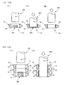
- Fig. 1 is a view of a connecting rod with bearings (i.e., bearing metal layers) as one example according to the present invention.
- Fig. 2 is a view for explaining a relevant step of a method of forming the bearing metal layer shown in Fig. 1, as one embodiment of the present invention.
- Fig. 3 is a view for explaining the method of forming the bearing metal layer.
- Fig. 4 is a view for explaining a draft employed in the method of forming the bearing metal layer.
- Fig. 5 is a view of examples of a cylindrical body formed of a bearing metal material, employed in the method of forming the bearing metal layer.
- Fig. 6 is a view for explaining control methods employed in the method of forming the bearing metal layer.
- Fig. 7 is a view for explaining a step of working the connecting rod after the bearing metal layers have been formed.
- Fig. 8 is a view for explaining another method of forming a bearing metal layer, as another embodiment of the present invention.
- Fig. 9 is a view for explaining a comparative example with which each of the embodiments of the present invention is compared.
- reference numeral 10 designates a connecting rod including a large end portion 12, a small end portion 14, and a rod portion 16 located between the two end portions 12, 14.
- the large end portion 12 has a large end hole 18 (i.e., a fitting hole) in which a crank pin fits
- the small end portion 14 has a small end hole 20 (i.e., a fitting hole) in which a piston pin fits.
- the crank pin is connected to the large end portion 12 such that the crank pin rotatably fits in the large end hole 18, and the piston pin is connected to the small end portion 14 such that the piston pin rotatably fits in the small end hole 20.
- a bearing metal layer 22 having a corresponding cross-sectional shape and having a cylindrical shape with a small wall thickness is directly joined and formed; and on an inner surface of the small end hole 20, a bearing metal layer 24 having a corresponding cross-sectional shape and having a cylindrical shape with a small wall thickness is directly joined and formed.
- the crank pin is connected to the large end portion 12 via the bearing metal layer 22 such that the crank pin rotatably fits in the large end hole 18, and the piston pin is connected to the small end portion 14 via the bearing metal layer 24 such that the piston pin rotatably fits in the small end hole 20.
- the large end portion 12 is constituted by two half portions that are fastened to each other with bolts and nuts.
- Figs. 2 and 3 illustrate a method of forming the bearing metal layer 22 on the inner surface of the large end hole 18.
- reference numeral 26 designates a rotary pressing tool including, as a main portion thereof, a disc-like rotary pressing portion 28.
- the rotary pressing portion 28 has a tapered surface 30 defined by an outer circumferential surface of an end portion thereof as seen in an axial direction thereof and a moving direction thereof (i.e., a downward direction as seen in the figure).
- the disc-like rotary pressing portion 28 additionally has, on an upper side of the tapered surface 30 as seen in the figure, an inner-diameter defining surface 32 that is continuous with the tapered surface 30 and extends straight parallel to the axial direction over a small dimension (i.e., a small length).
- the inner-diameter defining surface 32 defines an inner diameter of the bearing metal layer 22, described later. However, the straight, inner-diameter defining surface 32 may be omitted according to circumstances.
- a relationship between a diameter D and a thickness T of the disc-like rotary pressing portion 28 is as follows: T/D ⁇ 0.3.
- Reference numeral 34 designates a connection portion of the rotary pressing tool 26 that connects between the disc-like rotary pressing portion 28 and a rotating and pressing device.
- the connection portion 34 does not constitute a working portion. Therefore, an outer diameter of the connection portion 34 is made small enough to assure that when the rotary pressing tool 26 works the cylindrical formed body 38, the connection portion 34 is not brought into contact with the same 38.
- Reference numeral 30 designates a back-up member.
- the bearing metal material given as the cylindrical formed body 38 is inserted and fitted, as an inner member, inside the inner surface of the large end hole 18.
- the disc-like rotary pressing portion 28 of the rotary pressing tool 26 connected to the rotating and pressing device, more specifically described, the tapered surface 30 of the same 28 is pressed, while being rotated, against an upper end surface of the cylindrical formed body 38 as seen in the figure, so that the cylindrical formed body 38, i.e., the bearing metal material is heated and softened by the heat generated by the friction between the surface 30 and the body 38.
- the outer diameter of the disc-like rotary pressing portion 28 is smaller than an inner diameter of the large end hole 18, and is larger than an inner diameter of the cylindrical formed body 38.
- the rotary pressing tool 26, i.e., the disc-like rotary pressing portion 28 thereof is pressed in the axial direction thereof, i.e., the downward direction as seen in the figure, while the pressing portion 28 is rotated and the back-up member 36 is moved in the same direction, so that the bearing metal material plastically flows in both the same axial direction as the moving direction, and the radially outward direction.
- cylindrical, bearing metal layer 22 is directly and firmly formed and joined on the circular inner surface of the large end hole 18.
- a draft of the cylindrical formed body 38 worked by the rotary pressing portion 28 is not less than 7 %.
- This draft is defined as (t 1 /t 0 ) x 100 (%), where t 0 is an initial thickness of the wall of the cylindrical formed body 38 and t 1 is an after-working thickness of the wall of the same 38, as shown in Fig. 4.
- This draft is analogous with a draft of a plate material worked by, e.g., rolling.
- the bearing metal layer 22 can be advantageously pressed and joined on the inner surface of the large end hole 18.
- a cylindrical body shown in Fig. 5(A), that has such a cylindrical shape that is seamlessly continuous in a circumferential direction thereof in a state before it is inserted inside the inner surface of the large end hole 18.
- the cylindrical formed body 38 having the cylindrical shape seamlessly continuous in the circumferential direction may be formed by any of various working methods, such as casting, drawing, or extruding.
- cylindrical formed body 38 a cylindrical body, shown in Fig. 5(B), that is formed by curving a plate into a cylindrical shape.
- the bearing metal layer 22 is formed to have such a cylindrical shape that is seamlessly continuous in a circumferential direction thereof.
- bearing metal material a cast body, a sintered powder, a mechanical alloy, a rolled material, an expanded material, etc.
- the sintered powder or the cast body has a composition to have a specific function
- its embrittlement may lead to, e.g., fracture during a subsequent working operation.
- heating by friction causes plastic flowing and accordingly fracture or separation does not occur.
- the present method enjoys a high grainrefining effect.
- bearing metal material an Al-based alloy or a Cu-based alloy.
- the Al-based alloy may be an Al-Sn alloy or an Al-Bi alloy.
- the Cu-based alloy may be a Cu-Sn alloy
- the connecting rod 10 per se may be produced by any of various methods such as casting, forging, or sintering.
- a preferred material for the connecting rod 10 is a carbon steel such as S55C, a chrome molybdenum steel (i.e., a mechanical or structural steel) such as SCM435, a titanium alloy (e.g., Ti-6Al-4V), or an aluminum alloy
- the rotary pressing tool 26, in particular, the rotary pressing portion 28 thereof is formed of a material whose melting point is higher than that of the bearing metal material, and a maximum outer diameter of the rotary pressing portion 28 is made smaller than the inner diameter of the large end hole 18, as described above.
- a thickness of the bearing metal layer 22 joined and formed on the inner surface of the large end hole 18 is selected depending upon a difference of the inner diameter of the large end hole 18 and the outer diameter of the rotary pressing portion 28.
- the thickness of the bearing metal layer 22 can be arbitrarily changed by changing the outer diameter of the rotary pressing portion 28.
- the thickness of the bearing metal layer 22 ranges from about 0.5 mm to about 1.5 mm.
- the bearing metal layer 22 When the bearing metal layer 22 is formed, it is preferred to control temperatures such that the connecting rod 10 is pre-heated to improve a degree of bonding of the metal layer 22 to the rod 10 or such that the metal layer 22 is cooled by water when an excessively large amount of heat is generated.
- the durability of the rotary pressing tool 26, in particular, the rotary pressing portion 28 thereof can be effectively increased by subjecting a tool steel to a surface reforming such as a quenching or annealing heat treatment, a plasma powder cladding welding, or a metal spraying.
- a surface reforming such as a quenching or annealing heat treatment, a plasma powder cladding welding, or a metal spraying.
- an appropriate temperature at an interface of the rotary pressing portion 28 and the bearing metal material falls in a range from the melting point of the bearing metal material to a temperature lower than the melting point by about 100 °C.
- melting of a portion thereof raises no problem.
- the tapered surface 30 of the rotary pressing portion 28 may not be a strictly defined tapered surface so long as the diameter of the surface 30 gradually increases in a direction (i.e., an upward direction as seen in the figure) from a front end thereof toward a rear end thereof as seen in the moving direction.
- the tapered surface 30 may be a somewhat curved surface.
- the rotary pressing tool 26 may be used to heat, by friction, the cylindrical formed body 38 and thereby cause the same 38 to plastically flow, in such a manner that first the tapered surface 30 of the rotary pressing portion 28 is pressed, at a low pressure, against the upper end surface of the cylindrical formed body 38 so as to heat, by friction, the formed body 38, and then a large thrust is applied to the pressing portion 28 in the axial direction thereof so as to cause the formed body 38 to plastically flow.
- an axis of abscissas indicates time, and an axis of ordinates indicates pressure applied from the rotary pressing portion 28 to the cylindrical formed body 38.
- Fig. 6(A) shows a pattern for a case where a working operation is performed while the pressure is controlled to be constant
- Fig. 6(B) shows a pattern for a case where a working operation is performed while the displacement of the rotary pressing portion 28 is controlled to be constant
- Fig. 6(C) shows a pattern for a case where a working operation is performed while the pressure and the displacement of the pressing portion 28 are controlled in a mixed manner.
- the large end portion 12 is divided into two half portions, as shown in Fig. 7(II).
- those two half portions are fastened to each other with bolts and nuts, so that the two half portions are integral with each other.
- the rotary pressing tool 26 in particular, the tapered surface 30 of the disc-like rotary pressing portion 28 is pressed, while being rotated, against the cylindrical formed body 38 inserted inside the inner surface of the large end hole 18 so as to heat and soften, by friction, the formed body 38 and thereby cause the same 38 to plastically flow, whereby the bearing metal layer 22 is directly joined and formed on the inner surface of the large end hole 18. Therefore, it is not needed to separately produce the con-rod bearings each consisting of the back metal and the bearing metal, in the conventional method including the many steps. In addition, it is not needed to assemble the con-rod bearings with the connecting rod 10. Thus, the steps employed by the method of producing the connecting rod with the bearings can be reduced, and the cost needed to produce the connecting rod with the bearings can be decreased.
- the bearing metal layer 22 formed in this way is more strongly bonded to the inner surface of the large end hole 18, as compared with the case where the con rod bearing and the connecting rod are assembled with each other after they are produced separately from each other.
- the bearing metal layer 22 can be formed on the inner surface of the large end hole 18, such that the metal layer 22 has a constant thickness in the axial direction of the end hole 18.
- the present method does not need the back metals each having the thickness of from about 1 mm to about 1.5 mm that are used for the con rod bearings in the conventional method. Therefore, the size and weight of the connecting rod 10 as a whole can be reduced, which contributes to improving an output power and a fuel consumption of an engine for an automotive vehicle. Furthermore, since the back metals are not needed, a thermal conductivity and a heat radiating capability of the connecting rod 10 are improved, which additionally contributes to improving the output power of the engine.
- Fig. 8 shows another embodiment of the present invention.
- a plurality of connecting rods 10 are stacked on each other such that respective centerlines of respective large end holes 18 thereof coincide with each other, and a cylindrical body 38 formed of a bearing metal material and having a length corresponding to a sum of respective lengths of the large end holes 18 as measured in respective axial directions thereof is inserted in each of the large end holes 18 so as to be located in the each large end hole 18.
- the rotary pressing tool 26 is moved in the axial direction thereof, while being rotated, so that a bearing metal layer 22 is directly and continuously joined and formed on the respective inner surfaces of the respective large end holes 18 of the connecting rods 10, and then the connecting rods 10 are separated from each other so as to have the respective bearing metal layers 22.
- the bearing metal layers 22 can be efficiently joined and formed on the respective inner surfaces of the respective large end holes 18 of the multiplicity of connecting rods 10.
- the present producing method is particularly advantageous for a mass production of the connecting rods 10.
- Fig. 9 shows comparative examples in contrast to the above-described embodiments of the present invention.
- Fig. 9(A) shows an example where a bearing metal layer 22 is formed on an inner surface of a large end hole 18 of a single connecting rod 10; and Fig. 9(B) shows an example where a bearing metal layer 22 is continuously formed on respective inner surfaces of respective large end holes 18 of a plurality of connecting rods 10 that are stacked on each other.
- a bearing metal material 38A in the form of a block is set at a bottom of an inner space of the large end hole or holes 18, and a cylindrical pressing rod 40A is inserted, while being rotated, into the large end hole or holes 18.
- An advancing movement of the cylindrical pressing rod 40A in a downward direction as seen in the figure results in pressing the bearing metal material 38A, and the rotation of the pressing rod 40A heats and softens, by friction, the metal material 38A, whereby the metal material 38A is plastically flowed and is pressed (i.e., caused to creep) in an upward direction as seen in the figure from the bottom into a small clearance left between an outer circumferential surface of the pressing rod 40A and the inner surface or surfaces of the large end hole or holes 18.
- the bearing metal layer 22 is formed on the inner surface or surfaces of the large end hole or holes 18.
- the bearing metal material 38A when the bearing metal material 38A is heated and softened and plastically flows upward into the small clearance between the outer surface of the pressing rod 40A and the inner surface or surfaces of the end hole or holes 18, the metal material 38A cannot smoothly flow upward along the small clearance because of, e.g., a resistance produced by the friction thereof with the outer surface of the pressing rod 40A or the inner surface or surfaces of the end hole or holes 18.
- the temperature of the metal material 38A gradually lowers, the resistance exerted to the metal material 38A is amplified.
- the bearing metal layer 22 is excessively thick in a lower portion thereof and is excessively thin in an upper portion thereof, i.e., the thickness of the metal layer 22 is not sufficiently uniform.
- an entire outer circumferential surface, i.e., a large area of the pressing rod 40A is brought into frictional contact with the inner surface of the bearing metal material 38A or the bearing metal layer 22. Therefore, the heat generated by this frictional contact may cause seizure and thereby make it difficult to easily form and join the bearing metal layer 22.
Landscapes
- Engineering & Computer Science (AREA)
- Mechanical Engineering (AREA)
- General Engineering & Computer Science (AREA)
- Shafts, Cranks, Connecting Bars, And Related Bearings (AREA)
- Sliding-Contact Bearings (AREA)
Applications Claiming Priority (2)
| Application Number | Priority Date | Filing Date | Title |
|---|---|---|---|
| JP2004346962 | 2004-11-30 | ||
| PCT/JP2005/021874 WO2006059595A1 (ja) | 2004-11-30 | 2005-11-29 | 軸受付きコネクティングロッドの製造方法及び軸受付きコネクティングロッド |
Publications (2)
| Publication Number | Publication Date |
|---|---|
| EP1830077A1 true EP1830077A1 (de) | 2007-09-05 |
| EP1830077A4 EP1830077A4 (de) | 2011-05-04 |
Family
ID=36565029
Family Applications (1)
| Application Number | Title | Priority Date | Filing Date |
|---|---|---|---|
| EP05811477A Withdrawn EP1830077A4 (de) | 2004-11-30 | 2005-11-29 | Verfahren zur herstellung einer verbindungsstange mit lager und verbindungsstange mit lager |
Country Status (5)
| Country | Link |
|---|---|
| US (1) | US7836592B2 (de) |
| EP (1) | EP1830077A4 (de) |
| JP (1) | JP4560054B2 (de) |
| CN (1) | CN100554707C (de) |
| WO (1) | WO2006059595A1 (de) |
Cited By (4)
| Publication number | Priority date | Publication date | Assignee | Title |
|---|---|---|---|---|
| WO2013064655A1 (de) * | 2011-11-02 | 2013-05-10 | Mauser-Werke Oberndorf Maschinenbau Gmbh | Verfahren und einrichtung zum einbringen einer lagerbuchse |
| AT512972A1 (de) * | 2012-06-04 | 2013-12-15 | Berndorf Band Gmbh | Endlosband mit einem ringförmigen Bandkörper |
| EP2688709B1 (de) | 2011-03-22 | 2016-10-05 | Mauser-Werke Oberndorf Maschinenbau GmbH | Verfahren, werkzeug und maschine zum kalibrieren von buchsen |
| WO2017149037A1 (de) * | 2016-03-02 | 2017-09-08 | Mauser-Werke Oberndorf Maschinenbau Gmbh | Verfahren und eine einrichtung zum einwalzen von buchsen |
Families Citing this family (10)
| Publication number | Priority date | Publication date | Assignee | Title |
|---|---|---|---|---|
| JP5688568B2 (ja) * | 2008-07-15 | 2015-03-25 | 山野井精機株式会社 | 被加工金属部材に突起を形成する突起形成方法 |
| JP5691552B2 (ja) * | 2011-01-24 | 2015-04-01 | 日産自動車株式会社 | エンジンのコネクティングロッド及びその製造方法 |
| WO2013146608A1 (ja) * | 2012-03-30 | 2013-10-03 | 大豊工業株式会社 | 摺動部材、及び、摺動部材の製造方法 |
| DE102014001248A1 (de) * | 2014-02-03 | 2015-08-06 | Gkn Sinter Metals Engineering Gmbh | Pleuel-Kolben-Baugruppe mit einem Pleuel mit Kugelkopf |
| US9114481B1 (en) * | 2014-02-21 | 2015-08-25 | Siemens Energy, Inc | Inertia friction disk welding |
| DE102017129233A1 (de) * | 2017-12-08 | 2019-06-13 | Man Truck & Bus Ag | Vorrichtung, insbesondere Einlegehilfe, zur Gleitlagerschalenmontage |
| CN109048037B (zh) * | 2018-08-23 | 2020-12-01 | 常熟理工学院 | 基于搅拌摩擦加工制备Al-Pb合金耐磨层的方法 |
| CN112742981B (zh) * | 2020-12-18 | 2024-04-16 | 安徽创联汽车零部件有限公司 | 发动机止推片压接设备 |
| CN114406615B (zh) * | 2022-01-24 | 2023-03-31 | 中国科学院兰州化学物理研究所 | 一种整体式自润滑关节轴承润滑材料填设型腔的制造方法 |
| CN117428067B (zh) * | 2023-12-01 | 2024-04-23 | 河北海珉工矿集团有限公司 | 一种锚索托盘加工用冲压设备 |
Citations (5)
| Publication number | Priority date | Publication date | Assignee | Title |
|---|---|---|---|---|
| US5666637A (en) * | 1995-11-09 | 1997-09-09 | Nissan Motor Co., Ltd. | Method of manufacturing connecting rod |
| JP2000015718A (ja) * | 1998-07-01 | 2000-01-18 | Tokai Rubber Ind Ltd | ブッシュ装着用部材及びその製造方法 |
| JP2000312981A (ja) * | 1999-04-28 | 2000-11-14 | Daido Steel Co Ltd | 円柱内面のコーティング方法 |
| DE10124843A1 (de) * | 2001-05-22 | 2002-11-28 | Ina Schaeffler Kg | Gleitlager |
| JP2004174593A (ja) * | 2002-11-29 | 2004-06-24 | Japan Science & Technology Agency | 機能性膜の逐次コーティング方法 |
Family Cites Families (8)
| Publication number | Priority date | Publication date | Assignee | Title |
|---|---|---|---|---|
| DE3144335C2 (de) * | 1981-11-07 | 1983-09-29 | Goetze Ag, 5093 Burscheid | "Verfahren zur Herstellung von mit einer verschleißfesten Schicht zu versehenden rotationssymmetrischen Werkstücken" |
| JPS6345451A (ja) * | 1986-08-13 | 1988-02-26 | Toyota Motor Corp | ピストンリングの製造方法 |
| JPH0544842A (ja) * | 1991-08-16 | 1993-02-23 | Riken Corp | ピストンリングの製造法 |
| US5941651A (en) * | 1994-06-10 | 1999-08-24 | Di Serio; Thomas | Process for the fabrication of parts made of cast alloys with reinforcement zones |
| JPH09222117A (ja) | 1996-02-19 | 1997-08-26 | Mitsubishi Motors Corp | すべり軸受構造 |
| JP3707001B2 (ja) * | 2000-06-21 | 2005-10-19 | 宗到 橋本 | 表面微細加工処理装置 |
| JP2002327732A (ja) * | 2001-04-27 | 2002-11-15 | Kawasaki Heavy Ind Ltd | エンジンのコンロッド |
| JP2004308819A (ja) * | 2003-04-08 | 2004-11-04 | Motoaki Uemura | ベアリングヒーター |
-
2005
- 2005-11-29 WO PCT/JP2005/021874 patent/WO2006059595A1/ja active Application Filing
- 2005-11-29 US US11/791,906 patent/US7836592B2/en not_active Expired - Fee Related
- 2005-11-29 JP JP2006547938A patent/JP4560054B2/ja not_active Expired - Fee Related
- 2005-11-29 CN CNB2005800408594A patent/CN100554707C/zh not_active Expired - Fee Related
- 2005-11-29 EP EP05811477A patent/EP1830077A4/de not_active Withdrawn
Patent Citations (5)
| Publication number | Priority date | Publication date | Assignee | Title |
|---|---|---|---|---|
| US5666637A (en) * | 1995-11-09 | 1997-09-09 | Nissan Motor Co., Ltd. | Method of manufacturing connecting rod |
| JP2000015718A (ja) * | 1998-07-01 | 2000-01-18 | Tokai Rubber Ind Ltd | ブッシュ装着用部材及びその製造方法 |
| JP2000312981A (ja) * | 1999-04-28 | 2000-11-14 | Daido Steel Co Ltd | 円柱内面のコーティング方法 |
| DE10124843A1 (de) * | 2001-05-22 | 2002-11-28 | Ina Schaeffler Kg | Gleitlager |
| JP2004174593A (ja) * | 2002-11-29 | 2004-06-24 | Japan Science & Technology Agency | 機能性膜の逐次コーティング方法 |
Non-Patent Citations (1)
| Title |
|---|
| See also references of WO2006059595A1 * |
Cited By (6)
| Publication number | Priority date | Publication date | Assignee | Title |
|---|---|---|---|---|
| EP2688709B1 (de) | 2011-03-22 | 2016-10-05 | Mauser-Werke Oberndorf Maschinenbau GmbH | Verfahren, werkzeug und maschine zum kalibrieren von buchsen |
| WO2013064655A1 (de) * | 2011-11-02 | 2013-05-10 | Mauser-Werke Oberndorf Maschinenbau Gmbh | Verfahren und einrichtung zum einbringen einer lagerbuchse |
| CN103906599A (zh) * | 2011-11-02 | 2014-07-02 | 毛瑟-韦尔克奥伯恩多夫机械制造有限公司 | 用于插入轴承衬套的方法和装置 |
| AT512972A1 (de) * | 2012-06-04 | 2013-12-15 | Berndorf Band Gmbh | Endlosband mit einem ringförmigen Bandkörper |
| AT512972B1 (de) * | 2012-06-04 | 2014-06-15 | Berndorf Band Gmbh | Endlosband mit einem ringförmigen Bandkörper |
| WO2017149037A1 (de) * | 2016-03-02 | 2017-09-08 | Mauser-Werke Oberndorf Maschinenbau Gmbh | Verfahren und eine einrichtung zum einwalzen von buchsen |
Also Published As
| Publication number | Publication date |
|---|---|
| JPWO2006059595A1 (ja) | 2008-06-05 |
| CN100554707C (zh) | 2009-10-28 |
| US7836592B2 (en) | 2010-11-23 |
| WO2006059595A1 (ja) | 2006-06-08 |
| CN101065586A (zh) | 2007-10-31 |
| US20080216599A1 (en) | 2008-09-11 |
| EP1830077A4 (de) | 2011-05-04 |
| JP4560054B2 (ja) | 2010-10-13 |
Similar Documents
| Publication | Publication Date | Title |
|---|---|---|
| US7836592B2 (en) | Method of producing connecting rod with bearing | |
| US20140102164A1 (en) | Method and apparatus related to joining dissimilar metal | |
| CN109093048B (zh) | 一种大型机闸类锻件模具及锻造方法 | |
| US20090205453A1 (en) | Ring gear and manufacturing method for such a ring gear | |
| WO2007142298A1 (ja) | シールリング付シェル型ニードル軸受及びその製造方法 | |
| EP1422384B1 (de) | Verfahren zur herstellung einer komponente in einem turbolader mit variabler geometrie und durch das verfahren hergestellte komponente | |
| JP2000312981A (ja) | 円柱内面のコーティング方法 | |
| US6688154B2 (en) | Die for forging rotor, forge production system and forging method using the die, and rotor | |
| JP5556297B2 (ja) | 車輪支持用転がり軸受ユニットの軌道輪部材の製造方法 | |
| JP4319015B2 (ja) | 等速ジョイント用外輪部材の製造方法 | |
| JP2008296241A (ja) | 転がり軸受用軌道輪の製造方法 | |
| JP2002181047A (ja) | スラスト軸受およびその製造方法 | |
| US7504160B2 (en) | Sliding body and process for producing a sliding body, and its use | |
| CN112958768A (zh) | 一种采用径向扩孔法生产双金属滑动轴承的制造工艺 | |
| CN112958769A (zh) | 一种利用径向滚压方式生产双金属滑动轴承的制造方法 | |
| CN113059330B (zh) | 一种大口径壳体一体化成形方法 | |
| CN1027496C (zh) | 钢管式径向止推轴承毛坯加工方法 | |
| RU2804236C1 (ru) | Способ изготовления водоохлаждаемой оправки прошивного стана в виде двухслойного полого тела и штамп для его осуществления | |
| US10960459B2 (en) | Method of manufacturing a drum of an axial piston machine | |
| CN109622867B (zh) | 一种tc8-1钛合金盘件的等温锻造方法 | |
| Klocke et al. | Massive Forming | |
| CN111328303B (zh) | 用于由高强度合金材料制造结构构件的方法 | |
| JPH09280013A (ja) | 組立カムシャフト用カムピース | |
| CN115430799A (zh) | 盘轴及其制造方法 | |
| CN112935248A (zh) | 一种粉末冶金双金属滑动轴承的制造方法 |
Legal Events
| Date | Code | Title | Description |
|---|---|---|---|
| PUAI | Public reference made under article 153(3) epc to a published international application that has entered the european phase |
Free format text: ORIGINAL CODE: 0009012 |
|
| 17P | Request for examination filed |
Effective date: 20070521 |
|
| AK | Designated contracting states |
Kind code of ref document: A1 Designated state(s): DE FR |
|
| DAX | Request for extension of the european patent (deleted) | ||
| RBV | Designated contracting states (corrected) |
Designated state(s): DE FR |
|
| A4 | Supplementary search report drawn up and despatched |
Effective date: 20110406 |
|
| RIC1 | Information provided on ipc code assigned before grant |
Ipc: F16C 17/02 20060101ALI20110331BHEP Ipc: B21D 49/00 20060101ALI20110331BHEP Ipc: B23P 9/00 20060101ALI20110331BHEP Ipc: F16C 33/14 20060101ALI20110331BHEP Ipc: B23K 20/12 20060101ALI20110331BHEP Ipc: F16C 7/02 20060101ALI20110331BHEP Ipc: F16C 9/04 20060101AFI20110331BHEP |
|
| RAP1 | Party data changed (applicant data changed or rights of an application transferred) |
Owner name: KOSEI ALUMINUM CO., LTD. Owner name: JAPAN SCIENCE AND TECHNOLOGY AGENCY |
|
| 17Q | First examination report despatched |
Effective date: 20130102 |
|
| GRAP | Despatch of communication of intention to grant a patent |
Free format text: ORIGINAL CODE: EPIDOSNIGR1 |
|
| INTG | Intention to grant announced |
Effective date: 20130913 |
|
| STAA | Information on the status of an ep patent application or granted ep patent |
Free format text: STATUS: THE APPLICATION IS DEEMED TO BE WITHDRAWN |
|
| 18D | Application deemed to be withdrawn |
Effective date: 20140124 |