EP1827807B2 - Méthode et dispositif pour la fabrication de pneumatiques pour roues de véhicules - Google Patents
Méthode et dispositif pour la fabrication de pneumatiques pour roues de véhicules Download PDFInfo
- Publication number
- EP1827807B2 EP1827807B2 EP04806864.7A EP04806864A EP1827807B2 EP 1827807 B2 EP1827807 B2 EP 1827807B2 EP 04806864 A EP04806864 A EP 04806864A EP 1827807 B2 EP1827807 B2 EP 1827807B2
- Authority
- EP
- European Patent Office
- Prior art keywords
- respect
- auxiliary
- radially outer
- continuous elongated
- drum
- Prior art date
- Legal status (The legal status is an assumption and is not a legal conclusion. Google has not performed a legal analysis and makes no representation as to the accuracy of the status listed.)
- Active
Links
- 238000004519 manufacturing process Methods 0.000 title claims abstract description 69
- 238000000034 method Methods 0.000 title claims abstract description 56
- 239000013536 elastomeric material Substances 0.000 claims description 31
- 230000003014 reinforcing effect Effects 0.000 claims description 27
- 238000011161 development Methods 0.000 claims description 21
- 238000004804 winding Methods 0.000 claims description 16
- 238000004873 anchoring Methods 0.000 claims description 15
- 238000012546 transfer Methods 0.000 claims description 15
- 238000007493 shaping process Methods 0.000 claims description 9
- 238000006073 displacement reaction Methods 0.000 claims description 7
- 238000004073 vulcanization Methods 0.000 claims description 5
- 238000001125 extrusion Methods 0.000 claims description 2
- 239000011265 semifinished product Substances 0.000 description 15
- 239000000463 material Substances 0.000 description 7
- 239000011324 bead Substances 0.000 description 5
- 230000008021 deposition Effects 0.000 description 5
- 239000004753 textile Substances 0.000 description 4
- 238000013461 design Methods 0.000 description 3
- 230000008569 process Effects 0.000 description 3
- 230000015572 biosynthetic process Effects 0.000 description 2
- 239000000470 constituent Substances 0.000 description 2
- 238000010276 construction Methods 0.000 description 2
- 239000003431 cross linking reagent Substances 0.000 description 2
- 230000001419 dependent effect Effects 0.000 description 2
- 230000000694 effects Effects 0.000 description 2
- 239000012530 fluid Substances 0.000 description 2
- 230000006872 improvement Effects 0.000 description 2
- 230000009467 reduction Effects 0.000 description 2
- 238000013519 translation Methods 0.000 description 2
- 230000009471 action Effects 0.000 description 1
- 239000000654 additive Substances 0.000 description 1
- 239000007795 chemical reaction product Substances 0.000 description 1
- 238000005520 cutting process Methods 0.000 description 1
- 230000003247 decreasing effect Effects 0.000 description 1
- 239000000945 filler Substances 0.000 description 1
- 238000010438 heat treatment Methods 0.000 description 1
- 238000011065 in-situ storage Methods 0.000 description 1
- 230000003993 interaction Effects 0.000 description 1
- 230000007246 mechanism Effects 0.000 description 1
- 239000004033 plastic Substances 0.000 description 1
- 239000004014 plasticizer Substances 0.000 description 1
- 229920000642 polymer Polymers 0.000 description 1
- 239000000047 product Substances 0.000 description 1
- 239000012763 reinforcing filler Substances 0.000 description 1
- 238000005096 rolling process Methods 0.000 description 1
- 230000006641 stabilisation Effects 0.000 description 1
- 238000012360 testing method Methods 0.000 description 1
Images

Classifications
-
- B—PERFORMING OPERATIONS; TRANSPORTING
- B29—WORKING OF PLASTICS; WORKING OF SUBSTANCES IN A PLASTIC STATE IN GENERAL
- B29D—PRODUCING PARTICULAR ARTICLES FROM PLASTICS OR FROM SUBSTANCES IN A PLASTIC STATE
- B29D30/00—Producing pneumatic or solid tyres or parts thereof
- B29D30/06—Pneumatic tyres or parts thereof (e.g. produced by casting, moulding, compression moulding, injection moulding, centrifugal casting)
- B29D30/08—Building tyres
- B29D30/20—Building tyres by the flat-tyre method, i.e. building on cylindrical drums
- B29D2030/206—A plurality of building drums being mounted on a fixture or supporting device, e.g. turret or turntable
-
- B—PERFORMING OPERATIONS; TRANSPORTING
- B29—WORKING OF PLASTICS; WORKING OF SUBSTANCES IN A PLASTIC STATE IN GENERAL
- B29D—PRODUCING PARTICULAR ARTICLES FROM PLASTICS OR FROM SUBSTANCES IN A PLASTIC STATE
- B29D30/00—Producing pneumatic or solid tyres or parts thereof
- B29D30/06—Pneumatic tyres or parts thereof (e.g. produced by casting, moulding, compression moulding, injection moulding, centrifugal casting)
- B29D30/08—Building tyres
- B29D30/20—Building tyres by the flat-tyre method, i.e. building on cylindrical drums
- B29D2030/207—Building tyres by the flat-tyre method, i.e. building on cylindrical drums the drum supporting device being rotatable around a horizontal axis
-
- B—PERFORMING OPERATIONS; TRANSPORTING
- B29—WORKING OF PLASTICS; WORKING OF SUBSTANCES IN A PLASTIC STATE IN GENERAL
- B29D—PRODUCING PARTICULAR ARTICLES FROM PLASTICS OR FROM SUBSTANCES IN A PLASTIC STATE
- B29D30/00—Producing pneumatic or solid tyres or parts thereof
- B29D30/06—Pneumatic tyres or parts thereof (e.g. produced by casting, moulding, compression moulding, injection moulding, centrifugal casting)
- B29D30/08—Building tyres
- B29D30/20—Building tyres by the flat-tyre method, i.e. building on cylindrical drums
- B29D2030/208—Building tyres by the flat-tyre method, i.e. building on cylindrical drums the drum supporting device being rotatable around a vertical axis
-
- B—PERFORMING OPERATIONS; TRANSPORTING
- B29—WORKING OF PLASTICS; WORKING OF SUBSTANCES IN A PLASTIC STATE IN GENERAL
- B29D—PRODUCING PARTICULAR ARTICLES FROM PLASTICS OR FROM SUBSTANCES IN A PLASTIC STATE
- B29D30/00—Producing pneumatic or solid tyres or parts thereof
- B29D30/06—Pneumatic tyres or parts thereof (e.g. produced by casting, moulding, compression moulding, injection moulding, centrifugal casting)
- B29D30/08—Building tyres
- B29D30/20—Building tyres by the flat-tyre method, i.e. building on cylindrical drums
- B29D30/24—Drums
- B29D2030/241—Auxiliary drums used for temporary storage of the layers before application to the building drums
-
- B—PERFORMING OPERATIONS; TRANSPORTING
- B29—WORKING OF PLASTICS; WORKING OF SUBSTANCES IN A PLASTIC STATE IN GENERAL
- B29D—PRODUCING PARTICULAR ARTICLES FROM PLASTICS OR FROM SUBSTANCES IN A PLASTIC STATE
- B29D30/00—Producing pneumatic or solid tyres or parts thereof
- B29D30/06—Pneumatic tyres or parts thereof (e.g. produced by casting, moulding, compression moulding, injection moulding, centrifugal casting)
- B29D30/08—Building tyres
- B29D30/20—Building tyres by the flat-tyre method, i.e. building on cylindrical drums
- B29D30/24—Drums
- B29D30/242—Drums for manufacturing substantially cylindrical tyre components without cores or beads, e.g. treads or belts
-
- B—PERFORMING OPERATIONS; TRANSPORTING
- B29—WORKING OF PLASTICS; WORKING OF SUBSTANCES IN A PLASTIC STATE IN GENERAL
- B29D—PRODUCING PARTICULAR ARTICLES FROM PLASTICS OR FROM SUBSTANCES IN A PLASTIC STATE
- B29D30/00—Producing pneumatic or solid tyres or parts thereof
- B29D30/06—Pneumatic tyres or parts thereof (e.g. produced by casting, moulding, compression moulding, injection moulding, centrifugal casting)
- B29D30/08—Building tyres
- B29D30/20—Building tyres by the flat-tyre method, i.e. building on cylindrical drums
- B29D30/30—Applying the layers; Guiding or stretching the layers during application
- B29D30/3028—Applying the layers; Guiding or stretching the layers during application by feeding a continuous band and winding it helically, i.e. the band is fed while being advanced along the drum axis, to form an annular element
Definitions
- the present invention relates to a method for manufacturing tyres for vehicle wheels.
- the invention also pertains to a plant for manufacturing vehicle tyres, which may be employed to carry out the above mentioned manufacturing method, as well as to a plant for making tyres for vehicle wheels.
- a tyre for vehicle wheels generally comprises a carcass structure including at least one carcass ply having respectively opposite end flaps turned up loop-wise around annular anchoring structures, each of said anchoring structures being usually made up of a substantially circumferential annular insert onto which at leat one filling insert is applied, at a radially external position thereof.
- a belt structure comprising one or more belt layers, having textile or metallic reinforcing cords arranged at radial superposed relationship with each other and with the carcass structure, is associated to the latter.
- a tread band made of elastomeric material like other semifinished products which constitute the tyre, is applied to the belt structure at a radially external position thereof.
- elastomeric material is used to indicate a composition comprising at least one elastomeric polymer and at least one reinforcing filler.
- such composition further comprises additives such as, for example, a cross-linking agent and/or a plasticizer. Thanks to the presence of the cross-linking agent, such material can be cross-linked by heating, so as to form the end product.
- respective sidewalls of elastomeric material are also applied to the side surfaces of the carcass structure, each of them extending from one of the side edges of the tread band up to the respective annular anchoring structure at the beads, which sidewalls, depending on the different embodiments, can exhibit respective radially outer end edges either superposed on the side edges of the tread band so as to form a design scheme of the type usually referred to as "overlying sidewalls", or interposed between the carcass structure and the side edges of the tread band itself, in accordance with a design scheme of the type referred to as "underlying sidewalls".
- the carcass structure and the belt structure together with the respective tread band are made separately of each other in respective work stations, so as to be mutually assembled at a later time.
- the building of the carcass structure is carried out in a building station, and it first contemplates the deposition of the carcass ply or plies on a first drum usually identified as "building drum” to form a substantially cylindrical sleeve.
- the annular anchoring structures at the beads are fitted or formed on the opposite end flaps of the carcass ply or plies which in turn are turned up around the annular structures themselves so as to enclose them in a sort of loop.
- an outer sleeve is manufactured, which is substantially cylindrical as well, which comprises the belt layers laid down in radially superposed relationship with each other, and the tread band applied to the belt layers at a radially outer position thereof.
- the outer sleeve is then picked up from the auxiliary drum to be coupled with the carcass sleeve.
- the outer sleeve is arranged in coaxial relation around the carcass sleeve, and then the carcass ply or plies are shaped into a toroidal conformation by axially moving the beads close to each other and simultaneously admitting fluid under pressure into the carcass sleeve, so as to determine the application of the belt/tread band sleeve to the carcass structure of the tyre at a radially outer position thereof.
- Assembling of the carcass sleeve with the outer sleeve can be carried out on the same drum used for building the carcass sleeve, in which case reference is made to a "unistage manufacturing process".
- a manufacturing process of this type is described in document US 3,990, 931 , for example.
- assembling may be carried out on a so-called “shaping drum” onto which the carcass sleeve and outer sleeve are transferred, to manufacture the tyre according to a so-called “two-stage manufacturing process", as described in documents EP 0 613 757 and WO 98/12043 , for example.
- International patent application WO 98/12043 discloses a tire assembly method and apparatus which utilize at least two rotatable turrets that each have two drums and at least one transfer unit for transferring tire components from one turret to another.
- this apparatus features three turrets and two transfer units, wherein a carcass band is assembled on the drums of a first turret, the tread package is assembled on a third turret and-the complete tire carcass is assembled on a second turret, in between the first and third turrets. Simultaneous, continuous and sequential building and assembly of tire carcass bands and tread packages for a plurality of tires is provided by the disclosed method and apparatus
- the tread band is usually made of a continuously-extruded section member that, after being cooled for stabilisation of its geometrical conformation, is stored on suitable benches or reels.
- the semifinished product in the form of sections or of a continuous strip is then sent to a delivering unit which either picks up the sections or cuts the continuous strip into sections of predetermined length, each section constituting the tread band to be circumferentially applied onto the belt structure of a tyre being manufactured.
- Such continuous elongated element is obtained in situ and forms a plurality of coils the orientation and mutual-overlapping parameters of which are suitably managed so as to control the variations in thickness to be given to the tread band during the manufacture, based on a predetermined deposition scheme preset on an electronic computer, with a considerable increase of the quality characteristics of the tread band, which in turn positively influence the tyre performance and life.
- EP 0 873 852 discloses a method of forming a green tire comprising winding a rubber strip on an adjusting drum while extruding an unvulcanized rubber from an extruder in a form of a rubber strip in a length corresponding to the rubber quantity of a tire constituent portion, and forming said tire constituent portion by winding said rubber strip continuously a plurality of times on the outer circumference of a rotary support member, unwinding the rubber strip from the adjusting drum.
- EP 1106335 A2 A tire forming method and plant according to the preamble of claims 1 and 20 is disclosed by EP 1106335 A2 .
- the productivity of the finishing station is heavily affected by the inherent slowness of the coil winding step of the continuous elongated element of green elastomeric material.
- the Applicant intends to solve the problem of manufacturing a high quality tyre reconciling the different productivity rates of the building station of the carcass structure and of the finishing station intended to manufacture the substantially cylindrical belt structure/tread band sleeve also in the event that such sleeve includes a tread band made by winding coils of at least one continuous elongated element.
- the Applicant has found that great improvements are achieved in terms of overall productivity and quality of the product within the framework of a tyre manufacturing process which provides for the assembly of semifinished products, by adopting the following measures:
- the present invention relates, according to a first aspect thereof, to a method for manufacturing tyres for vehicle wheels as defined by claim 1.
- the above mentioned method can be carried out by means of a plant for manufacturing tyres for vehicle wheels as defined in claim 20 attached herewith.
- the invention relates to a plant for making tyres for vehicle wheels, comprising a manufacturing plant as defined above and at least one vulcanisation station for vulcanising the tyres manufactured in said manufacturing plant
- a plant for manufacturing tyres for vehicle wheels adapted to carry out a manufacturing method according to a preferred embodiment of the present invention, is generally indicated at 1.
- a tyre that can be manufactured, by the plant 1 is generally indicated at 2 in Figure 2 and:
- the tyres 2 essentially comprise a carcass structure 3 having a substantially toroidal conformation, a belt structure 4 having a substantially cylindrical conformation, circumferentially extending around the carcass structure 3, a tread band 5 applied to the belt structure 4 at a radially outer position thereof, and a pair of sidewalls 6 laterally applied, on opposite sides, to the carcass structure 3 and each extending from a side edge of the tread band 5 up to a radially inner edge of the carcass structure 3.
- each sidewall 6 essentially comprises a layer of elastomeric material, having a suitable thickness and may have a radially outer end tailpiece 6a at least in part covered by the axial end of the tread band 5, as shown in solid line in Figure 2 , according to a construction scheme of the type usually identified as "underlying sidewalls".
- the radially outer end tailpieces 6a of the sidewalls 6 can be laterally superposed on the corresponding axial ends of the tread band 5, as shown in dashed line in Figure 2 , to realise a construction scheme of the type usually identified as "overlying sidewalls".
- the carcass structure 3 comprises a pair of annular anchoring structures 7 integrated in regions usually identified as "beads", each of them being for example made up of a substantially circumferential annular insert 8, usually called “bead core”, and carrying an elastomeric filler 9 at a radially outer position thereof.
- the end flaps 10a of one or more carcass plies 10 comprising textile or metallic cords extending transversely with respect to the circumferential development of the tyre 2, possibly according to a predetermined inclination between the two annular anchoring structures 7.
- the belt structure 4 comprises in turn at least one belt layer, preferably at least two belt layers 11a, 11b comprising reinforcing cords made of a suitable material, for example metallic or textile cords.
- said reinforcing cords are suitably inclined with respect to the circumferential development of the tyre 2, according to respectively crossed orientations between one belt layer and the other.
- the belt structure 4 further comprises at least one belt layer 12 at a radially outer position with respect to the belt layers 11 a, 11b and including at least one reinforcing cord, preferably a plurality of cords circumferentially wound according to coils axially arranged side by side and usually called "zero-degree cords" in the art.
- the belt structure 4 can comprise a belt layer 12 including zero-degree cords substantially extending for the entire transversal development of the belt structure 4; alternatively, the belt structure 4 can comprise a pair of belt layers 12, each including zero-degree cords, arranged near opposite shoulder zones of the tyre 2 and axially extending along a portion of limited width, as schematically shown in Figure 2 .
- the belt structure 4 may also incorporate, at a radially outer position with respect to the belt layers 11a, 11b, a further layer 13 made of elastomeric material preferably including a plurality of reinforcing cords, usually referred to as "breaker layer" and intended to prevent foreign bodies from entering the underlying belt layers.
- the tread band 5 may essentially consist of a single elastomeric material or, alternatively, it may comprise portions consisting of respective elastomeric materials having appropriate composition and appropriate mechanical and chemical-physical characteristics.
- These portions may be constituted by one or more radially superposed layers having suitable thickness, by suitably shaped sectors arranged according to a predetermined configuration along the axial development of the tread band or by a combination of both.
- the tread band 5 may include a radially inner layer or base layer, essentially consisting of a first elastomeric material having appropriate composition and mechanical and chemical-physical characteristics, for example adapted to reduce the rolling resistance of the tyre, and a radially outer layer essentially consisting of a second elastomeric material having composition and mechanical and chemical-physical characteristics differing from the first elastomeric material, for example adapted to optimise the grip performance on wet surfaces and the wear resistance of the tyre.
- the individual components of the carcass structure 3 and of the belt structure 4, such as in particular the annular anchoring structures 7, the carcass plies 10, the belt layers 11a, 11b and the elements of elastomeric material (strip-like elements) including at least one reinforcing cord and intended to form the belt layer 12 and optionally the breaker layer 13, are supplied to the plant 1 in the form of semifinished products made during preceding manufacturing steps, to be suitably assembled with each other according to the step described hereinafter.
- the plant 1 comprises a building station 14 intended to build a substantially cylindrical carcass structure 3 comprising one or more carcass plies 10 operatively associated to the annular anchoring structures 7 axially spaced apart from each other.
- the building station 14 comprises a primary drum 15, not described in detail as it can be made in any convenient manner, on which the carcass ply or plies 10 are preferably wound; said plies come from a feeding line 16 along which they are cut into sections of appropriate length related to the circumferential extension of the primary drum 15, before being applied thereon to form a so-called substantially cylindrical "carcass sleeve".
- the building station 14 also comprises a line (not shown) for feeding the sidewalls 6, which line supplies a semifinished product in the form of a continuous strip of elastomeric material from which sections of predetermined length are cut out, said length being related to the circumferential extension of the primary drum 15 and of the tyre 2 to be manufactured.
- the building station 14 can be provided with a further building drum (not shown) on which the assembly of the carcass structure 3 components and possibly also of the sidewalls 6 takes place, and with a transfer device (also not shown) for transferring the assembled carcass sleeve onto the primary drum 15.
- a further building drum not shown
- a transfer device also not shown
- the plant 1 further comprises a finishing station 17 intended to manufacture a substantially cylindrical sleeve comprising:
- the finishing station 17 comprises in turn a displacing apparatus 18 adapted to support a first auxiliary drum 19 and a second auxiliary drum 20 and to position said auxiliary drums 19, 20 at a plurality of working positions at which the operating steps required for manufacturing the above substantially cylindrical sleeve are carried out.
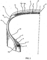
- the displacing apparatus 18 is adapted to position the auxiliary drums 19, 20 at a first working position, indicated with letter A in Figure 1 , wherein the belt structure 4 is assembled, at least one second working position, indicated with letter B in Figure 1 , wherein the tread band 5 is applied, and a picking position C of the substantially cylindrical sleeve manufactured in the finishing station 17.
- the picking position C of the substantially cylindrical sleeve substantially coincides with the first working position A.
- the first working position A and the second working position B are defined in different zones of the finishing station 17 and, preferably, they are defined at opposite sides of the displacing apparatus 18.
- the finishing station 17 comprises an apparatus for applying the belt structure 4 on the same auxiliary drum, generally indicated at 21, adapted to operatively interact with the auxiliary drum 19, 20 arranged at the first working position A by the displacing apparatus 18.
- the applying apparatus 21 comprises in turn at least one delivery device 24 of the belt layers 11a, 11b arranged at the first working position A for operatively interacting with the auxiliary drum 19, 20 arranged at said working position by the displacing apparatus 18.
- the delivery device 24 may comprise, in a way known per se, at least one feeding line 24a, along which the semifinished products in the form of a continuous strip are caused to move forward, said strip being then cut into sections of a length corresponding to the circumferential development of the auxiliary drums 19, 20 simultaneously with the formation of the respective belt layers 11a, 11b on the same drums.
- the applying apparatus 21 of the finishing station 17 further comprises at least one delivery device 22 of a strip-like element 23 of green elastomeric material including at least one reinforcing cord, preferably a plurality of textile or metallic reinforcing cords, strip-like element 23 that is applied at a radially outer position with respect to the belt layers 11a, 11b to form axially contiguous circumferential coils intended to form the belt layer 12.
- the delivery device 22 is arranged at the first working position A for operatively interacting with the auxiliary drum 19, 20 arranged at said working position by the displacing apparatus 18.
- the apparatus 21 further comprises at least one delivery device of a further belt layer preferably including a plurality of reinforcing cords, arranged at the first working position A for operatively interacting with the auxiliary drum 19, 20 arranged at said working position by the displacing apparatus 18 for forming the aforementioned breaker layer 13.
- the finishing station 17 further comprises at least two delivery members 25, 26, of respective continuous elongated elements 27, 28 of green elastomeric material, which delivery members are arranged at the second working position B for operatively interacting with the auxiliary drum 19, 20 arranged at said working position by the displacing apparatus 18.
- the delivery members 25, 26 of the continuous elongated elements 27, 28 are arranged at the second working position B for operatively interacting at opposite sides of the auxiliary drum 19, 20 arranged at said working position by the displacing apparatus 18.
- the delivery members 25, 26, are adapted to lay down the continuous elongated elements 27, 28 according to contiguous circumferential coils on a belt structure 4 previously assembled on the auxiliary drum 19 or 20 arranged at the second working position B.
- the delivery members 25, 26 can for example comprise an extruder or, alternatively, an applicator roller or other member adapted to deliver the continuous elongated elements 27, 28 at a radially outer position with respect to the belt structure 4 supported by the auxiliary drum 19 or 20 at the second working position, B, simultaneously with winding of the elongated elements themselves at a radially outer position with respect to the belt structure 4 as will be better described hereinafter
- each of the delivery members 25, 26 comprises at least one extruder indicated in Figure 1 with reference numerals 29, 30.
- the displacing apparatus 18 of the preferred embodiment shown in Figure 1 comprises at least one drum rotation unit, preferably a pair of rotation units 31, 32, adapted to rotate the auxiliary drums 19, 20 about their geometrical axis
- the displacing apparatus 18 is of the substantially turret-like type and is adapted to support the auxiliary drums 19, 20 at positions angularly offset with each other, for example offset at an angle of about 180°.
- the displacing apparatus 18 is further provided with at least one driving unit 35 adapted to rotate the displacing apparatus 18 as a whole about a substantially vertical rotation axis Y-Y so as to position the auxiliary drums 19, 20 at the above first and second working positions A, B.
- the auxiliary drums 19, 20 and the respective driving units 31, 32 are slidably supported by the displacing apparatus 18 by a supporting carriage, not better shown in Figure 1 , which is in turn slidably mounted on a rotatable supporting platform 39 of the displacing apparatus 18.
- each auxiliary drum 19, 20 is in integral translating motion with the corresponding rotation unit 31, 32 along the rotatable supporting platform 39.
- the displacing apparatus 18 comprises at least one drum translating unit adapted to carry out controlled axial movements of the drums 19, 20 at the working positions A, B or, preferably, at the picking position C of the substantially cylindrical sleeve including the belt structure 4 and the tread band 5 manufactured in the finishing station 17.
- said drum translating unit causes controlled axial movements not only of the auxiliary drums 19, 20 but also of the relevant rotation units 31, 32.
- the displacing apparatus 18 comprises a pair of drum translating units 33, 34, for example of the type comprising a worm screw adapted to engage with a corresponding nut thread associated to said carriage supporting the auxiliary drums 19, 20.
- drum translating units can comprise actuating mechanisms differing from those indicated above by way of example and selectable by a man skilled in the art as a function of specific application requirements.
- the drum translating units 33, 34 of the displacing apparatus 18 move the drums 19, 20 between the working positions A, B or the picking position C and a stand-by position defined between said positions and the rotation axis Y-Y of the, displacing apparatus 18.
- said stand-by positions of the auxiliary drums 19, 20 are defined within the outer perimeter of the rotatable supporting platform 39.
- the drum translating units 33, 34 move the drums 19, 20 along a radial direction passing through the rotation axis Y-Y of the displacing apparatus 18 as illustrated by the double arrows F3, F4 in Figure 1 .
- drum translating units 33, 34 thus allow to achieve the following advantageous technical effects:
- the drum translating units 33, 34 allow to carry out a controlled deposition of the continuous elongated elements 27, 28 while maintaining stationary the delivery members 25, 26 with a simplification of the mechanical application system of the continuous elongated elements and; thereby, with a reduction of the costs for realising the plant 1.
- the plant 1 further comprises at least one transfer device 36 of the substantially cylindrical sleeve manufactured in the finishing station 17, adapted to operatively interact with one of the auxiliary drums 19, 20 at the above-identified picking position C - in this case substantially coinciding with the first working position A - for transferring the substantially cylindrical sleeve manufactured in the finishing station 17 at a radially outer position with respect to the carcass structure 3 built in the building station 14.
- the transfer device 36 preferably has a substantially annular conformation and is operated in a way known per se (not shown) so as to be arranged around the auxiliary drum 19, 20 positioned at the picking position C for picking up the substantially cylindrical sleeve including the belt structure 4 and the tread band 5 manufactured in the finishing station 17 and for transferring said sleeve coaxially to the carcass structure 3 built in the building station 14.
- the plant 1 may further comprise a third delivery member of a respective continuous elongated element of green elastomeric material arranged at the picking position C (for example coinciding with the first working position A) of the substantially cylindrical sleeve manufactured in the finishing station 17 for operatively interacting with the auxiliary drum 19, 20 positioned therein by the displacing apparatus 18.
- the plant 1 allows to apply the tread band 5 both in the working position B, and in the picking position C (for example coinciding with the first working position A) of the substantially cylindrical sleeve, wherever this is required to meet specific application requirements.
- the plant 1 further comprises at least one apparatus (not shown being known per se ) for shaping the carcass structure 3 according to a substantially toroidal shape so as to associate the substantially cylindrical sleeve comprising the belt structure and the tread band 5 manufactured in the finishing station 17 to the carcass structure 3.
- at least one apparatus for shaping the carcass structure 3 according to a substantially toroidal shape so as to associate the substantially cylindrical sleeve comprising the belt structure and the tread band 5 manufactured in the finishing station 17 to the carcass structure 3.
- this shaping apparatus is adapted to operatively interact with the primary drum 15 within the building station 14 so as to carry out, as it will be better understood hereinafter, a so-called unistage manufacturing process.
- the plant 1 finally comprises a control unit 37 by means of which an operator 38 can program and manage the various operating steps that can be carried out by the same manufacturing plant.
- the method will be illustrated with reference to steady-state working conditions, as illustrated in Figure 1 , wherein the auxiliary drum 19 is in the first working position A and does not support any semifinished products, whereas the auxiliary drum 20 is in the second working position B and supports a belt structure 4 assembled on said drum in a previous step of the method.
- a substantially cylindrical carcass structure 3 comprising at least one carcass ply 10 operatively associated to the annular anchoring structures 7 axially spaced apart from each other, is built in the building station 14.
- the carcass ply or plies 10 coming from the feeding line 16 along which they are cut into sections of appropriate length, related to the circumferential development of the primary drum 15, before being applied thereto, are wound on the primary drum 15 to form a so-called substantially cylindrical "carcass sleeve".
- the annular anchoring structures 7 are fitted onto the end flaps 10a of ply/plies 10 to subsequently carry out the turning-up of the end flaps themselves to cause an engagement of the anchoring structures 7 into the loops thus formed by the turned-up ply/plies 10.
- the tyre sidewalls 6 may also be applied to the carcass sleeve, which sidewalls come from at least one respective sidewall-feeding line (not shown) supplying a semifinished product in the form of a continuous strip of elastomeric material, from which sections of predetermined length are cut out, said length being related to the circumferential development of the primary drum 15 and of the tyre 2 to be manufactured.
- the method of the invention provides for the manufacture, in the finishing station 17, of a substantially cylindrical sleeve comprising the tread band 5 applied at a radially outer position with respect to the belt structure 4 including at least one belt layer, in this preferred embodiment the belt layers 11a, 11b, 12 and optionally 13.
- this substantially cylindrical sleeve occurs at least in part simultaneously with the assembly of the components of the carcass structure 3 in the form of cylindrical sleeve (or carcass sleeve) on the primary drum 15.
- the manufacture of the substantially cylindrical sleeve including the belt structure 4 and the tread band 5 carried out in the finishing station 17 comprises the operating steps illustrated hereinafter.
- a first belt structure 4 is assembled at the first working position A on the first auxiliary drum 19 of the finishing station 17.
- the assembly step of the first belt structure 4 provides in the first place for carrying out the steps of applying at a radially outer position with respect to the first auxiliary drum 19 the first belt layer 11a comprising respective reinforcing cords inclined with respect to the circumferential development direction of the sleeve and of applying at a radially outer position with respect to the first belt layer 11a the second belt layer 11b comprising reinforcing cords inclined along a crossed direction with respect to said reinforcing cords belonging to the first belt layer 11a.
- these steps are carried out by means of the delivery device 24 of the belt layers which operatively interacts with the auxiliary drum 19 positioned at the first working position A by the displacing apparatus 18 and by the rotation unit 31 which rotates the auxiliary drum 19 about its geometrical axis during the application of the various semifinished products.
- the feeding line 24a of the delivery device 24 delivers semifinished products in the form of a continuous strip, which are then cut into sections of a length corresponding to the circumferential development of the auxiliary drum 19 simultaneously with the formation of the respective belt layers 11a, 11b on the same drum, which is simultaneously rotated by the rotation unit 31.
- the assembly step of the first belt structure 4 therefore provides for carrying out the step of applying at a radially outer position with respect to the first auxiliary drum 19 at least one strip-like element 23 of green elastomeric material including the reinforcing cord(s) to form axially contiguous circumferential coils, so as to obtain the belt layer 12 including reinforcing cords substantially parallel to the circumferential development direction of the substantially cylindrical sleeve being manufactured.
- said strip-like element 23 is applied at a radially outer position with respect to the second belt layer 11b substantially along the entire transversal development of the first belt structure 4 or, alternatively, only at opposed axial ends of the underlying belt layers 11a, 11b.
- this step is carried out by the delivery device 22 of the application apparatus 21, which is also arranged at the first working position A for operatively interacting with the auxiliary drum 19 arranged therein by the displacing apparatus 18.
- the assembly, step of the first belt structure 4 finally provides for carrying out the step of applying the breaker layer 13 of green elastomeric material preferably including a plurality of reinforcing cords preferably inclined with respect to the circumferential development direction of the sleeve, at a radially outer position with respect to the underlying belt layers, in this case at a radially outer position with respect to the belt layer 12.
- this step is carried out by a further delivery device of a belt layer preferably including a plurality of reinforcing cords (delivery device not shown for simplicity in Figure. 1 ), arranged at the first working position A for operatively interacting with the auxiliary drum 19 arranged therein by the displacing apparatus 18.
- a further delivery device of a belt layer preferably including a plurality of reinforcing cords (delivery device not shown for simplicity in Figure. 1 ), arranged at the first working position A for operatively interacting with the auxiliary drum 19 arranged therein by the displacing apparatus 18.
- the manufacture of the substantially cylindrical sleeve including the belt structure and the tread band provides for forming a tread band 5 at a radially outer position with respect to a second belt structure 4 assembled on the second auxiliary drum 20 in a previous operating step of the method.
- this forming step of the tread band 5 on the second auxiliary drum 20 arranged at the second working position B is carried out at least in part simultaneously with the step of assembling the first belt structure 4 on the first auxiliary drum 19 arranged at the first working position A.
- the method of the invention provides for applying a tread band 5 at the second working position B at a radially outer position with respect to a second belt structure 4 previously assembled on the second auxiliary drum 20 of the finishing station 17 at the first working position A.
- the application step of the tread band 5 is carried out at the second working position B by laying down according to respective predetermined paths said at least two continuous elongated elements 27, 28 of green elastomeric material at a radially outer position with respect to the second belt structure 4 assembled on the second auxiliary drum 20.
- the continuous elongated elements 27, 28 are laid down at opposite sides of the second auxiliary drum 20 arranged at the second working position B by the displacing apparatus 18.
- the continuous elongated elements 27, 28 consist of respective elastomeric materials having different mechanical and/or chemical-physical characteristics so as to impart the desired performance to the tread band 5.
- the application step of the tread band 5 is carried out by the delivery members 25, 26 arranged at the second working position B for operatively interacting with the auxiliary drum 20 arranged therein by the displacing apparatus 18.
- the delivery of the continuous elongated elements 27, 28 is carried out by extrusion through the extruders 29, 30 of the delivery members 25, 26.
- the continuous elongated elements 27, 28 delivered by each extruder 29, 30 can advantageously possess a flattened section, so as to modulate the thickness of the elastomeric layer formed by them at a radially outer position with respect to the belt structure 4 by changing the overlapping amount of the contiguous coils and/or the orientation of the profile along a transversal direction of each elongated element 27, 28 coming from the corresponding extruder 29, 30 with respect to the underlying surface.
- the continuous elongated elements 27, 28 are laid down according to contiguous circumferential coils, preferably axially arranged side by side and/or radially superposed, at a radially outer position with respect to the second belt structure 4 supported by the auxiliary drum 20 at the second working position B.
- the application step of the tread band 5 is carried out by delivering the continuous elongated elements 27, 28 by means of the delivery members 25, 26 arranged at the second working position B near the second auxiliary drum 20, simultaneously with winding of the continuous elongated elements 27, 28 on said drum.
- the controlled relative displacements between the second auxiliary drum 20 and the delivery members 25, 26 are carried out by moving the second auxiliary drum 20 with respect to said delivery members.
- the continuous elongated elements 27, 28 are delivered by the extruders 29, 30 simultaneously with a controlled rotation movement of the auxiliary drum 20 about its geometrical axis and a controlled translation movement of said drum with respect to the delivery members 25, 26, for example along a direction substantially parallel to said axis.
- this rotation-translation movement of the auxiliary drum 20 is carried out by means of the displacing apparatus 18, in particular thanks to the action of the rotation unit 32 and of the translating unit 34 of such apparatus.
- a tread band 5 including a pair of radially superposed layers, respectively inner and outer according to a configuration known in the art with the term of "cap-and-base”.
- the application step of the tread band 5 is carried out at the second working position B by laying down one of the aforementioned continuous elongated elements, for example the continuous elongated element 27, at a radially outer position with respect to the second belt structure 4 supported by the auxiliary drum 20 along substantially its entire transversal development so as to form a radially inner layer of the tread band 5.
- the application step of the tread band 5 provides for laying down the second continuous elongated element 28 at a radially outer position with respect to the radially inner layer of tread band 5 thus formed.
- the laying down of the second continuous elongated element 28 is carried out by substantially the entire transversal development of said radially inner layer so as to form a radially outer layer of the tread band 5.
- the laying down of the continuous elongated elements 27, 28 according to contiguous circumferential coils axially arranged side by side and/or radially superposed is carried out in two consecutive steps.
- a tread band 5 including two or more axially aligned sectors having specific mechanical characteristics according to a configuration which allows to achieve a plurality of advantageous technical effects, such as for example an improved resistance to the transversal stresses acting on the tread band 5 during use of the tyre 2, or the possibility of keeping the grip performance of the tyre 2 substantially constant as the tread band 5 wears out.
- the application step of the tread band 5 is carried out at the second working position B by laying down one of said continuous elongated elements, for example the continuous elongated element 27, at a radially outer position with respect to at least one portion of the second belt structure 4 supported by the auxiliary drum 20 so as to form a corresponding portion of the tread band 5.
- the application step of the tread band 5 provides for laying down the second continuous elongated element 28 at an axially aligned position with respect to the above portion formed by the continuous elongated element 27, so as to form a further portion of the tread band 5.
- the laying down of the continuous elongated elements 27, 28 can be carried out both in consecutive steps and at least in part simultaneously.
- the method of the invention provides for carrying out the steps of positioning the first auxiliary drum 19 supporting the first belt structure 4 at the second working position B and of positioning at the picking position C of the finishing station 17 the second auxiliary drum 20 supporting the substantially cylindrical sleeve including the tread band 5 applied at a radially outer position with respect to the second belt structure 4.
- the picking position C of the substantially cylindrical sleeve thus manufactured substantially coincides with the first working position A.
- said steps of positioning the auxiliary drums 19 and 20 respectively at the second working position B and at the first working position A are carried out at least in part simultaneously with each other.
- the displacing apparatus 18 is of the substantially turret-like type and supports the auxiliary drums 19, 20 at positions angularly offset with each other, said positioning steps of the auxiliary drums 19 and 20 are carried out by rotating the displacing apparatus 18 about the substantially vertical rotation axis Y-Y. In particular, such rotary motion is carried out thanks to the driving unit 35.
- the position of the auxiliary drums 19 and 20 is effectively exchanged practically simultaneously by simply rotating the displacing apparatus 18 about the rotation axis Y-Y, for example according to one of the two directions of rotation, clockwise and counter clockwise, indicated by the arrows F1 and respectively F2 in Figure 1 .
- the method of the invention comprises the further step of translating the auxiliary drums 19, 20 towards the rotation axis Y-Y of the displacing apparatus 18 before carrying out the rotation step of such apparatus.
- said step is carried out by the drum translating units 33 and 34 by translating both auxiliary drums 19, 20 and the relevant rotation units 31, 32, which are preferably translationally integral with the same drums.
- the auxiliary drums 19, 20 and the relevant rotation units 31, 32 are translated towards the rotation axis Y-Y of the displacing apparatus 18 and are arranged at the above stand-by position defined inside the outer perimeter of the rotatable supporting platform 39 of such apparatus.
- auxiliary drums 19, 20 of the displacing apparatus 18 are arranged in this case at a safe distance from both the control unit 37 and the operator 38 during the rotation of the displacing apparatus 18, as schematically illustrated in dotted line in Figure 1 .
- the finishing station 17 is in an operating condition in which:
- the method of the invention provides for the step of transferring the substantially cylindrical sleeve from the picking position C of the finishing station 17 at a radially outer position with respect to the carcass structure 3 built in the meantime in the building station 14.
- this transfer step is carried out by the substantially ring-shaped transfer device 36 according to methods known per se in the art.
- the finishing station 17 is at an operating condition in which the second auxiliary drum 20 is already arranged at the first working position A and ready to support a new belt structure 4 thanks to the operating interaction with the application apparatus 21 arranged at said working position A.
- the finishing station 17 is at an operating conditions totally similar to the starting condition indicated above, except for the fact that the two auxiliary drums 19, 20 have exchanged their position.
- the method of the invention provides for cyclically repeating the steps described above which are adapted to manufacture the substantially cylindrical sleeve including the belt structure 4 and the tread band 5, by assembling a new belt structure 4 on the second auxiliary drum 20 at the first working position A, by applying substantially simultaneously at the second working position B a new tread band 5 at a radially outer position with respect to the belt structure 4 previously assembled on the first auxiliary drum 19, exchanging the place of the two drums at the end of these assembling and application steps, and so on.
- a new substantially cylindrical sleeve including the belt structure 4 and the tread band 5 is obtained, supported at the picking position C (in this case position A) alternatively by one of the two auxiliary drums 19, 20 of the finishing station 17.
- Such sleeve is then transferred from the picking position C of the finishing station 17 at a radially outer position with respect to a new carcass structure 3 built in the building station 14 according to the method described above.
- the steps of manufacturing the substantially cylindrical sleeve including the tread band 5 and the belt structure 4 and of transferring such sleeve from the picking position C of the finishing station 17 are carried out in a time interval substantially equal to or smaller than, the time for carrying out the step of building the carcass structure 3 in the building station 14.
- the assembly of the substantially cylindrical sleeve including the tread band 5 and the belt structure 4 with the carcass structure 3 not toroidally-shaped yet is carried out on the same primary drum 15 of the building station 14 used for building the carcass sleeve, thus integrating a unistage manufacturing process.
- a high quality level of the tyre 2 being manufactured is ensured in this way, thanks to the limited number of operations during the assembly of green semifinished products still in a substantially plastic state.
- Such semifinished products are thus subjected to a correspondingly limited number of potentially deforming stresses, thus advantageously limiting the risk of undesired structural alternations of the green tyre being manufactured.
- the transfer device 36 having a substantially annular conformation is operated so as to be placed around the auxiliary drum 19, or 20 arranged at the picking position C for picking up the substantially cylindrical sleeve including the belt structure 4 and the tread band 5 from the same drum.
- the auxiliary drum 19, 20 disengages said sleeve which is then axially translated by the transfer device 36 to be placed in a coaxially centred position on the primary drum 15 supporting the carcass sleeve.
- the assembly of the carcass sleeve with the tread band 5/belt structure z sleeve may be carried out on a so-called shaping drum onto which the carcass sleeve and the tread band 5/belt structure 4 sleeve are transferred, to manufacture the tyre according to a so-called "two-stage manufacturing process".
- the method further comprises after said transfer step the step of shaping the substantially cylindrical carcass structure 3 according to a substantially toroidal shape so as to associate the same to the substantially cylindrical sleeve including the tread band 5 and the belt structure 4 transferred at a radially outer position with respect to the carcass structure.
- this shaping step is carried out by axially moving the annular anchoring structures 7 close to each other and simultaneously admitting fluid under pressure into the assembly consisting of the carcass structure 3 and of the substantially cylindrical sleeve including the tread band 5 and the belt structure 4, so as to place the carcass ply(ies) 10 in contact against the inner surface of the belt structure 4 held by the transfer device 36.
- a green tyre is manufactured which can be removed from the primary drum 15 or from the shaping drum to be subjected to a usual vulcanisation step carried out in a vulcanisation station (not shown) of a plant for making a tyre (not shown) comprising the manufacturing plant 1 described above.
- the method and the apparatus described above allow to manufacture a tyre 2 having a different structure, for example by applying further layers or elements at the first working position A and/or at the second working position B and/or at the picking position C.
- the method of the invention may provide for the further step of applying at the picking position C (for example coinciding with the first working position A) at a radially outer position with respect to the belt structure 4 supported by the auxiliary drum 19, 20 arranged therein, an additional first or last continuous elongated element of green elastomeric material according to a respective predetermined path, so as to begin or complete the tread band 5 at the picking position C.
- tread band 5 it is advantageously possible to form the tread band 5 using three different elastomeric materials delivered by the delivery members 25, 26 arranged at the second working position B and by the delivery member arranged at the picking position C of the finishing station 17.
- this application step is carried out according to the methods described above, that is, by delivering such continuous elongated element by means of an extruder of a further delivery member (not shown) arranged at the picking position C (for example coinciding with the first working position A) near the auxiliary drum 19, 20 arranged therein and by winding the continuous elongated element on said drum.
- this further delivery member may be provided with a respective actuating group (not shown) adapted to move such member to and from the auxiliary drum 19, 20 arranged at the picking position C (for example coinciding with the first working position A), so as not to interfere with the subsequent picking operations of the substantially cylindrical sleeve including the belt structure 4 and the tread band 5.
- a respective actuating group (not shown) adapted to move such member to and from the auxiliary drum 19, 20 arranged at the picking position C (for example coinciding with the first working position A), so as not to interfere with the subsequent picking operations of the substantially cylindrical sleeve including the belt structure 4 and the tread band 5.
- the manufacturing method and apparatus according to the invention in their possible alternative embodiments, fully achieve the object of manufacturing a high quality tyre reconciling the different productivity rates of the building station 14 of the carcass structure and of the finishing station 17 intended to manufacture the substantially cylindrical sleeve including a belt structure 4 provided with at least a belt layer and with a tread band 5 formed by winding coils of at least one continuous elongated element.
- the method according to the invention achieves the aforementioned object thanks to a sequence of operating steps that can be carried out by a structurally simple and easy to manage manufacturing plant 1.
- the manufacturing plant 1 of the invention can be arranged downstream of an existing station for building the carcass structures, thus increasing the productivity of the tyre manufacturing plant which incorporates the same.
- the assembly of the carcass sleeve with the outer belt structure/tread band sleeve can be carried out on the same drum used for building the carcass sleeve, integrating a unistage manufacturing process which makes it possible to maximise the productivity of the manufacturing plant and the quality characteristics of the tyres manufactured by the same.
- auxiliary drums will be preferably supported by the displacing apparatus 18 at positions angularly offset with each other by an angle substantially equal to about 360°/n where n is the total number of auxiliary drums.
- the plant 1 comprises a suitable number of application apparatuses 21 of the belt layers and/or of delivery members of respective continuous elongated elements arranged at the working positions defined in the finishing station 17 for operatively interacting with the auxiliary drums arranged therein by the displacing apparatus 18.
Landscapes
- Engineering & Computer Science (AREA)
- Mechanical Engineering (AREA)
- Tyre Moulding (AREA)
- Micro-Organisms Or Cultivation Processes Thereof (AREA)
Claims (32)
- Procédé de fabrication de pneus pour roues de véhicule, comprenant les étapes consistant à :a) construire dans une station de montage (14) une structure de carcasse sensiblement cylindrique (3) comprenant au moins une nappe de carcasse (10) associée fonctionnellement à des structures d'ancrage annulaires (7) espacées axialement les unes des autres ;b) fabriquer dans une station de finition (17) un manchon sensiblement cylindrique comprenant une bande de roulement (5) appliquée en une position radialement extérieure par rapport à une structure de ceinture (4) comprenant au moins une couche de ceinture (11a, 11b, 12), ladite étape b) comprenant les étapes consistant à :b1) assembler une première structure de ceinture (4) à une première position de travail (A) sur un premier tambour auxiliaire (19) de la station de finition (17) ;b2) appliquer une bande de roulement (5) à une deuxième position de travail (B) à une position radialement extérieure par rapport à une deuxième structure de ceinture (4) précédemment assemblée sur un deuxième tambour auxiliaire (20) dans la première position de travail (A) de la station de finition (17), ladite étape d'application étant exécutée en déposant selon des spires circonférentielles contiguës un premier (27) et un deuxième (28) élément allongé continu de matériau élastomère non vulcanisé à une position radialement extérieure par rapport à ladite deuxième structure de ceinture (4) ;b3) positionner le premier tambour auxiliaire (19) supportant la première structure de ceinture (4) à ladite deuxième position de travail (B) ;b4) positionner ledit deuxième tambour auxiliaire (20) supportant le manchon sensiblement cylindrique ainsi obtenu à une position d'extraction (C) de la station de finition (17) ;dans lequel lesdites positions de travail (A, B) de la station de finition (17) sont décalées angulairement l'une par rapport à l'autre ; etc) transférer ledit manchon sensiblement cylindrique de ladite position d'extraction (C) de la station de finition (17) à une position radialement extérieure par rapport à une structure de carcasse (3) fabriquée pendant ce temps dans la station de montage (14) ;
dans lequel ladite étape b2) est exécutée en distribuant lesdits premier (27) et deuxième (28) éléments allongés continus à partir d'éléments de distribution respectifs (25, 26) placés au niveau de ladite deuxième position de travail (B) près dudit deuxième tambour auxiliaire (20), simultanément à l'enroulement des éléments allongés continus (27, 28) sur ledit tambour (20) ;
dans lequel lesdites étapes b1) à b4) sont répétées de manière cyclique ; dans lequel les étapes b1) et b2) sont exécutées au moins en partie simultanément l'une par rapport à l'autre ; et
dans lequel les étapes b3) et b4) sont exécutées au moins en partie simultanément l'une par rapport à l'autre ;
caractérisé en ce que lesdits tambours auxiliaires (19, 20) sont supportés à des positions angulairement décalées l'une par rapport à l'autre par un appareil de déplacement sensiblement en forme de tourelle (18) ; en ce que ladite étape b2) est réalisée en exécutant, simultanément à l'application desdits éléments allongés continus (27, 28), les étapes consistant à :d) imprimer à au moins l'un desdits tambours auxiliaires (19, 20) portant la première ou la deuxième structure de ceinture (4) un mouvement de rotation autour d'un axe géométrique de celui-ci, afin de répartir dans le sens de la circonférence lesdits éléments allongés continus (27, 28) à une position radialement extérieure par rapport à ladite première ou à ladite deuxième structure de ceinture (4) ;e) exécuter des déplacements relatifs maîtrisés entre ledit au moins tambour auxiliaire (19, 20) et les éléments de distribution (25, 26) en déplaçant ledit au moins un tambour auxiliaire (19, 20) par rapport aux éléments de distribution (25, 26) pour former avec lesdits éléments allongés continus (27, 28) une pluralité desdites spires circonférentielles contiguës agencées mutuellement côte à côte pour définir la bande de roulement (5) ; et en ce que
lesdites étapes d) et e) sont exécutées par ledit appareil de déplacement (18) actif sur ledit au moins un tambour auxiliaire (19, 20) ;
lesdites étapes b3) et b4) sont exécutées en faisant tourner ledit appareil de déplacement (18) autour d'un axe de rotation sensiblement vertical (Y-Y). - Procédé selon la revendication 1, dans lequel lesdites étapes b) et c) sont exécutées dans un intervalle de temps sensiblement égal à ou inférieur au temps nécessaire pour exécuter ladite étape a) de construction de la structure de carcasse (3).
- Procédé selon la revendication 1, dans lequel ladite étape b1) comprend en outre les étapes consistant à :i) appliquer à une position radialement extérieure par rapport au premier tambour auxiliaire (19) une première couche de ceinture (11a) comprenant des premiers câbles de renforcement inclinés par rapport à la direction de développement circonférentielle du manchon ; etii) appliquer à une position radialement extérieure par rapport à la première couche de ceinture (11a) une deuxième couche de ceinture (11b) comprenant des deuxièmes câbles de renforcement inclinés le long d'une direction croisée par rapport auxdits premiers câbles de renforcement.
- Procédé selon la revendication 1 ou 3, dans lequel ladite étape b1) comprend en outre l'étape consistant à :iii) appliquer à une position radialement extérieure par rapport au premier tambour auxiliaire (19) un élément en forme de bande (23) de matériau élastomère non vulcanisé comprenant au moins un câble de renforcement pour former des spires circonférentielles axialement contiguës, afin d'obtenir une couche de ceinture (12) comprenant des câbles de renforcement sensiblement parallèles à la direction de développement circonférentielle du manchon.
- Procédé selon la revendication 4, dans lequel ledit élément en frome de bande (23) de matériau élastomère non vulcanisé est appliqué à une position radialement extérieure par rapport à la deuxième couche de ceinture (11b).
- Procédé selon l'une quelconque des revendications 1, 3, 4 ou 5, dans lequel ladite étape b1) comprend en outre l'étape consistant à :iv) appliquer une couche supplémentaire (13) de matériau élastomère non vulcanisé à une position radialement extérieure par rapport à ladite au moins une couche de ceinture (11a, 11b, 12), ladite couche (13) comprenant une pluralité de câbles de renforcement.
- Procédé selon la revendication 1, dans lequel ladite étape b2) est exécutée à ladite deuxième position de travail (B) en déposant ledit premier élément allongé continu (27) de matériau élastomère non vulcanisé à une position radialement extérieure par rapport à ladite deuxième structure de ceinture (4) sensiblement sur tout son développement transversal afin de former une couche radialement intérieure de bande de roulement (5).
- Procédé selon la revendication 7, dans lequel ladite étape b2) est exécutée à ladite deuxième position de travail (B) en déposant ledit deuxième élément allongé continu (28) à une position radialement extérieure par rapport à ladite couche radialement intérieure de la bande de roulement (5) sensiblement sur tout son développement transversal afin de former une couche radialement extérieure de bande de roulement (5).
- Procédé selon la revendication 1, dans lequel ladite étape b2) est exécutée à ladite deuxième position de travail (B) en déposant ledit premier élément allongé continu (27) à une position radialement extérieure par rapport à au moins une partie de ladite deuxième structure de ceinture (4) afin de former une partie correspondante de la bande de roulement (5).
- Procédé selon la revendication 9, dans lequel ladite étape b2) est exécutée à ladite deuxième position de travail (B) en déposant ledit deuxième élément allongé continu (28) à une position axialement alignée par rapport à ladite au moins une partie de la bande de roulement (5) formée par ledit premier élément allongé continu (27), afin de former une partie supplémentaire de la bande de roulement (5).
- Procédé selon la revendication 1, dans lequel ladite étape b) comprend en outre l'étape consistant à :b5) appliquer selon un chemin prédéterminé respectif un troisième élément allongé continu de matériau élastomère non vulcanisé à ladite position d'extraction (C) à une position radialement extérieure par rapport à ladite deuxième structure de ceinture (4).
- Procédé selon l'une quelconque des revendications 7 à 10, dans lequel lesdits premier (27) et deuxième (28) éléments allongés continus sont déposés à des côtés opposés du deuxième tambour auxiliaire (20).
- Procédé selon la revendication 11, dans lequel ladite étape b5) est exécutée en distribuant ledit troisième élément allongé continu depuis un élément de distribution respectif placé à ladite position d'extraction (C) près de l'un desdits tambours auxiliaires (19, 20), simultanément à l'enroulement de l'élément allongé continu sur l'un desdits tambours auxiliaires (19, 20).
- Procédé selon l'une quelconque des revendications 1 ou 13, dans lequel la distribution desdits éléments allongés continus (27, 28) est exécutée par extrusion à travers lesdits éléments de distribution (25, 26).
- Procédé selon la revendication 13, dans lequel ladite étape b5) est réalisée en exécutant, simultanément à l'application desdits éléments allongés continus (27, 28), les étapes consistant à :d) imprimer à au moins l'un desdits tambours auxiliaires (19, 20) portant la première ou la deuxième structure de ceinture (4) un mouvement de rotation autour d'un axe géométrique de celui-ci, afin de répartir dans le sens de la circonférence ledit troisième élément allongé continu à une position radialement extérieure par rapport à ladite première ou à ladite deuxième structure de ceinture (4) ;e) exécuter des déplacements relatifs maîtrisés entre ledit au moins tambour auxiliaire (19, 20) et l'élément de distribution placé à ladite position d'extraction (C) pour former avec ledit troisième élément allongé continu une pluralité de spires agencées mutuellement côte à côte pour définir la bande de roulement (5).
- Procédé selon la revendication 15, dans lequel lesdits déplacements sont exécutés en déplaçant ledit au moins un tambour auxiliaire (19, 20) par rapport audit élément de distribution placé à la position d'extraction (C).
- Procédé selon la revendication 1, dans lequel au moins l'un desdits tambours auxiliaires (19, 20) est supporté de façon glissante par ledit appareil de déplacement (18) et dans lequel le procédé comprend l'étape supplémentaire de translation dudit au moins un tambour auxiliaire (19, 20) vers l'axe de rotation (Y-Y) de l'appareil de déplacement (18) avant d'exécuter ladite étape de rotation dudit appareil (18).
- Procédé selon la revendication 1, dans lequel la position d'extraction (C) du manchon cylindrique coïncide sensiblement avec ladite première position de travail (A).
- Procédé selon la revendication 1, comprenant en outre après ladite étape c), l'étape consistant à donner une forme sensiblement toroïdale à ladite structure de carcasse (3) et audit manchon sensiblement cylindrique transféré à une position radialement extérieure par rapport à celle-ci, afin d'associer ledit manchon à ladite structure de carcasse (3).
- Installation (1) pour la fabrication de pneus pour roues de véhicule comprenant :a) une station de montage (14) pour construire une structure de carcasse sensiblement cylindrique (3) comprenant au moins une nappe de carcasse (10) associée fonctionnellement à des structures d'ancrage annulaires (7) espacées axialement les unes des autres ;b) une station de finition (17) pour fabriquer un manchon sensiblement cylindrique comprenant une bande de roulement (5) appliquée à une position radialement extérieure par rapport à une structure de ceinture (4) comprenant au moins une couche de ceinture (11a, 11b, 12), ladite station de finition (17) comprenant :b1) un premier tambour auxiliaire (19) ;b2) un deuxième tambour auxiliaire (20) ;b3) un appareil de déplacement (18) adapté pour supporter lesdits tambours auxiliaires (19, 20) et pour positionner lesdits tambours auxiliaires (19, 20) à une première position de travail (A) dans laquelle ladite structure de ceinture (4) est assemblée, à une deuxième position de travail (B) dans laquelle ladite bande de roulement (5) est appliquée et à une position d'extraction (C) dudit manchon sensiblement cylindrique ; lesdites première (A) et deuxième (B) positions de travail étant définies dans des zones différentes de la station de finition (17) ;b4) au moins deux éléments de distribution (25, 26) pour appliquer la bande de roulement (5) à une position radialement extérieure par rapport à la structure de ceinture (4) en déposant selon des spires circonférentielles contiguës des éléments allongés continus respectifs (27, 28) de matériau élastomère non vulcanisé, lesdits éléments de distribution (25, 26) étant placés à ladite deuxième position de travail (B) pour interagir fonctionnellement avec l'un desdits tambours auxiliaires (19, 20) ;c) au moins un dispositif de transfert (36) du manchon sensiblement cylindrique fabriqué dans la station de finition (17), adapté pour interagir fonctionnellement avec l'un desdits tambours auxiliaires (19, 20) à ladite position d'extraction (C) pour transférer ledit manchon sensiblement cylindrique à une position radialement extérieure par rapport à une structure de carcasse (3) construite dans la station de montage (14) ;
dans laquelle lesdites positions de travail (A, B) de la station de finition (17) sont décalées angulairement l'une par rapport à l'autre ;
dans laquelle ledit appareil de déplacement (18) comprend au moins au moins une unité de rotation de tambour (31, 32) adaptée pour faire tourner les tambours auxiliaires (19, 20) autour d'un axe géométrique de ceux-ci ; caractérisée en ce que ledit appareil de déplacement (18) est du type sensiblement en tourelle et est adapté pour supporter lesdits tambours auxiliaires (19, 20) à des positions angulairement décalées l'une par rapport à l'autre ; en ce que
ladite installation comprend au moins une unité d'entraînement (35) adaptée pour faire tourner ledit appareil de déplacement (18) autour d'un axe de rotation sensiblement vertical (Y-Y) ; et en ce que
ledit appareil de déplacement (18) comprend au moins une unité de translation de tambour (33, 34) adaptée pour exécuter des mouvement axiaux maîtrisés desdits tambours auxiliaires (19, 20) auxdites positions de travail (A, B). - Installation (1) selon la revendication 20, comprenant en outre au moins un dispositif de distribution (24) de couches de ceinture placées à ladite première position de travail (A) pour interagir fonctionnellement avec l'un desdits tambours auxiliaires (19, 20).
- Installation (1) selon l'une quelconque des revendications 20 ou 21, comprenant en outre au moins un dispositif de distribution (22) d'un élément en forme de bande (23) de matériau élastomère non vulcanisé comprenant au moins un câble de renforcement, placé à ladite première position de travail (A) pour interagir fonctionnellement avec l'un desdits tambours auxiliaires (19, 20) afin de former une couche de ceinture (12) comportant des câbles de renforcement sensiblement parallèles à la direction de développement circonférentielle du manchon.
- Installation (1) selon l'une quelconque des revendications 20 à 22, comprenant au moins un autre dispositif de distribution supplémentaire d'une couche de ceinture (13) comprenant une pluralité de câbles de renforcement, placés à ladite première position de travail (A) pour interagir fonctionnellement avec l'un desdits tambours auxiliaires (19, 20).
- Installation (1) selon l'une quelconque des revendications 20 à 23, comprenant en outre au moins un troisième élément de distribution d'un troisième élément allongé continu respectif de matériau élastomère non vulcanisé placé à ladite position d'extraction (C) pour interagir fonctionnellement avec l'un desdits tambours auxiliaires (19, 20).
- Installation (1) selon l'une quelconque des revendications 20 ou 24, dans laquelle les éléments de distribution (25, 26) desdits éléments allongés continus (27, 28) comprennent au moins une extrudeuse (29, 30).
- Installation (1) selon l'une quelconque des revendications 20 ou 24, dans laquelle lesdits tambours auxiliaires (19, 20) sont supportés de façon glissante par ledit appareil de déplacement (18) selon une direction radiale passant par un axe de rotation (Y-Y) de l'appareil de déplacement (18).
- Installation (1) selon la revendication 24, dans laquelle au moins une unité de translation de tambour (33, 34) est adaptée pour exécuter des mouvements axiaux maîtrisés desdits tambours auxiliaires (19, 20) à ladite position d'extraction (C).
- Installation (1) selon l'une quelconque des revendications 20 ou 27, dans laquelle ladite unité de translation de tambour (33, 34) de l'appareil de déplacement (18) déplace lesdits tambours auxiliaires (19, 20) entre lesdites positions de travail (A, B) ou ladite position d'extraction (C) et une position d'attente définie entre lesdites positions de travail (A, B) ou la position d'extraction (C) et ledit axe de rotation (Y-Y) de l'appareil de déplacement (18).
- Installation (1) selon la revendication 20, dans laquelle lesdits éléments de distribution (25, 26) des éléments allongés continus (27, 28) sont placés à ladite deuxième position de travail (B) pour interagir fonctionnellement à des côtés opposés de l'un desdits tambours auxiliaires (19, 20).
- Installation (1) selon la revendication 20, dans laquelle la position d'extraction (C) du manchon cylindrique coïncide sensiblement avec ladite première position de travail (A).
- Installation (1) selon la revendication 20, comprenant en outre au moins un appareil pour donner à ladite structure de carcasse (3) une forme sensiblement toroïdale afin d'associer le manchon sensiblement cylindrique comprenant la structure de ceinture (4) et la bande de roulement (5) à ladite structure de carcasse (3).
- Installation (1) pour la fabrication de pneus pour roues de véhicule, comprenant une installation de fabrication (1) selon l'une quelconque des revendications 20 à 31 et au moins une station de vulcanisation pour vulcaniser les pneus obtenus dans ladite installation de fabrication (1).
Applications Claiming Priority (1)
| Application Number | Priority Date | Filing Date | Title |
|---|---|---|---|
| PCT/IT2004/000699 WO2006064525A1 (fr) | 2004-12-16 | 2004-12-16 | Méthode et équipements pour la fabrication de pneumatiques pour roues de véhicules |
Publications (3)
| Publication Number | Publication Date |
|---|---|
| EP1827807A1 EP1827807A1 (fr) | 2007-09-05 |
| EP1827807B1 EP1827807B1 (fr) | 2010-02-17 |
| EP1827807B2 true EP1827807B2 (fr) | 2017-08-30 |
Family
ID=34960437
Family Applications (1)
| Application Number | Title | Priority Date | Filing Date |
|---|---|---|---|
| EP04806864.7A Active EP1827807B2 (fr) | 2004-12-16 | 2004-12-16 | Méthode et dispositif pour la fabrication de pneumatiques pour roues de véhicules |
Country Status (8)
| Country | Link |
|---|---|
| US (2) | US8226785B2 (fr) |
| EP (1) | EP1827807B2 (fr) |
| JP (1) | JP4932733B2 (fr) |
| CN (1) | CN101084107B (fr) |
| AT (1) | ATE457868T1 (fr) |
| BR (1) | BRPI0419156B1 (fr) |
| DE (1) | DE602004025632D1 (fr) |
| WO (1) | WO2006064525A1 (fr) |
Families Citing this family (19)
| Publication number | Priority date | Publication date | Assignee | Title |
|---|---|---|---|---|
| US20080202667A1 (en) * | 2004-12-16 | 2008-08-28 | Gianni Mancini | Method and Plant For Manufacturing Tyres For Vehicle Wheels |
| WO2006064525A1 (fr) | 2004-12-16 | 2006-06-22 | Pirelli Tyre S.P.A. | Méthode et équipements pour la fabrication de pneumatiques pour roues de véhicules |
| WO2006137131A1 (fr) * | 2005-06-22 | 2006-12-28 | Toyo Tire & Rubber Co., Ltd. | Procédé de moulage pneumatique et dispositif de rotation/déplacement d’un pied de déplacement/support de tambour lors d’un procédé de moulage |
| KR101429671B1 (ko) * | 2008-04-18 | 2014-08-13 | 피렐리 타이어 소시에떼 퍼 아찌오니 | 타이어 조립방법 및 기기 |
| JP4621272B2 (ja) * | 2008-08-04 | 2011-01-26 | 住友ゴム工業株式会社 | 生タイヤ成形装置 |
| KR101517537B1 (ko) * | 2008-12-11 | 2015-05-04 | 피렐리 타이어 소시에떼 퍼 아찌오니 | 차륜용 타이어를 제조하는 공정 및 장치 |
| RU2576598C2 (ru) | 2009-12-21 | 2016-03-10 | Пирелли Тайр С.П.А. | Способ и установка для сборки шин |
| KR101980670B1 (ko) | 2009-12-22 | 2019-05-21 | 피렐리 타이어 소시에떼 퍼 아찌오니 | 차륜용 생타이어 건조방법 및 설비 |
| DE102010037571A1 (de) * | 2010-09-16 | 2012-03-22 | Continental Reifen Deutschland Gmbh | Vorrichtung und Verfahren zur Herstellung einer Bodenschicht eines Vollreifens |
| MX336255B (es) * | 2011-04-28 | 2016-01-13 | Pirelli | Proceso y planta para construir llantas para ruedas de vehiculo. |
| NL2007058C2 (nl) | 2011-07-06 | 2013-01-08 | Vmi Holland Bv | Samenstel en werkwijze voor het vervaardigen van een groene band. |
| NL2007485C2 (nl) | 2011-09-27 | 2013-03-28 | Vmi Holland Bv | Samenstel en werkwijze voor het vervaardigen van een groene band en/of luchtveer. |
| JP5841816B2 (ja) * | 2011-11-24 | 2016-01-13 | 東洋ゴム工業株式会社 | 空気入りタイヤの製造方法及び空気入りタイヤの製造装置 |
| JP5431442B2 (ja) * | 2011-12-02 | 2014-03-05 | ピレリ・タイヤ・ソチエタ・ペル・アツィオーニ | 車両の車輪用タイヤを製造するための方法及びプラント |
| ITMI20112349A1 (it) * | 2011-12-22 | 2013-06-23 | Pirelli | Processo ed apparato per la produzione di pneumatici per ruote di veicoli |
| US20140027063A1 (en) * | 2012-07-25 | 2014-01-30 | Frederic Marie Bernard Marechal | Tire building machine with extendable drums |
| US20170144400A1 (en) * | 2015-11-24 | 2017-05-25 | The Goodyear Tire & Rubber Company | Method for manufacturing a single belt/overlay component for a pneumatic tire |
| CN109263106A (zh) * | 2018-10-09 | 2019-01-25 | 北京北人增材制造技术有限公司 | 全钢子午线轮胎胎面组合件贴合系统 |
| DE112021001251A5 (de) * | 2020-02-24 | 2023-07-20 | Harburg-Freudenberger Maschinenbau Gmbh | Verfahren und Vorrichtung zur Herstellung von Reifen |
Citations (3)
| Publication number | Priority date | Publication date | Assignee | Title |
|---|---|---|---|---|
| US4753707A (en) † | 1986-04-08 | 1988-06-28 | The Firestone Tire & Rubber Company | Twin rotary drum tire manufacturing unit |
| EP1106335A2 (fr) † | 1999-12-07 | 2001-06-13 | The Yokohama Rubber Co., Ltd. | Procédé et installation pour la confection de pneumatiques |
| WO2004041521A1 (fr) † | 2002-11-05 | 2004-05-21 | Pirelli Pneumatici S.P.A. | Procede et appareil de realisation d'un pneumatique |
Family Cites Families (42)
| Publication number | Priority date | Publication date | Assignee | Title |
|---|---|---|---|---|
| US2407152A (en) | 1943-01-30 | 1946-09-03 | Wingfoot Corp | Method for building pneumatic tires |
| BE637479A (fr) | 1962-09-18 | |||
| US3775220A (en) | 1971-03-01 | 1973-11-27 | Amf Inc | Apparatus for building tires |
| US3990931A (en) | 1972-07-06 | 1976-11-09 | Uniroyal, S.A. | Tire building apparatus and method |
| US3850219A (en) | 1972-08-18 | 1974-11-26 | Uniroyal Inc | Steel-belted radial ply tires with o{20 {0 textile cap hand |
| IT1081053B (it) | 1976-05-17 | 1985-05-16 | Pirelli | Perfezionamento alla struttura resistente dei pneumatici per ruote di veicoli |
| US4427473A (en) * | 1979-02-22 | 1984-01-24 | Nrm Corporation | Belt folding machine and method |
| DE2934936A1 (de) * | 1979-08-29 | 1981-03-19 | Bayer Ag, 5090 Leverkusen | Wickelreifen |
| JPS59120438A (ja) * | 1982-12-27 | 1984-07-12 | Bridgestone Corp | タイヤ成形ドラム拡縮装置 |
| US4805872A (en) | 1983-01-17 | 1989-02-21 | The Firestone Tire & Rubber Company | Shaping turret |
| GB8411820D0 (en) * | 1984-05-09 | 1984-06-13 | Bates W & A Ltd | Manufacture |
| IT1184525B (it) | 1985-04-30 | 1987-10-28 | Pirelli | Pneumatico asimmetrico per ruote di veicoli |
| IT1189672B (it) * | 1986-05-20 | 1988-02-04 | Firestone Int Dev Spa | Metodo per la realizzazione a caldo di pneumatici |
| GB8619617D0 (en) * | 1986-08-12 | 1986-09-24 | Apsley Metals Ltd | Tyre building machinery |
| JPH022046A (ja) * | 1988-06-10 | 1990-01-08 | Nec Data Terminal Ltd | 多目的シリアルプリンタ |
| JPH0299322A (ja) * | 1988-10-06 | 1990-04-11 | Toyo Tire & Rubber Co Ltd | 自動車タイヤの二次成形方法 |
| JPH02147231A (ja) | 1988-11-29 | 1990-06-06 | Yokohama Rubber Co Ltd:The | タイヤ成形方法及びその装置 |
| US5007974A (en) | 1989-06-09 | 1991-04-16 | The Goodyear Tire & Rubber Company | Method of making a belt overlay for pneumatic tires |
| SU1657409A1 (ru) | 1989-07-04 | 1991-06-23 | Всесоюзный Научно-Исследовательский И Конструкторский Институт По Оборудованию Для Шинной Промышленности | Способ формировани протектора |
| DE4108260A1 (de) * | 1991-03-14 | 1992-09-17 | Continental Ag | Verfahren und vorrichtung zur herstellung von laufstreifen/guertelpaketen fuer fahrzeugluftreifen |
| JP3187954B2 (ja) * | 1992-07-21 | 2001-07-16 | 三菱重工業株式会社 | タイヤ成形システム |
| DE4305260A1 (de) | 1993-02-20 | 1994-08-25 | Haeberle Gerhard Fa | Werkstückspannvorrichtung |
| NL1002306C2 (nl) | 1996-02-12 | 1997-08-13 | Vmi Epe Holland | Samenstel van inrichtingen voor het bouwen van een groene band voor voertuigen. |
| BR9612739A (pt) * | 1996-09-18 | 1999-08-24 | Goodyear Tire & Rubber | Processo e aparelho para montar simultaneamente uma s-rie de pneus |
| US6139668A (en) | 1996-09-18 | 2000-10-31 | The Goodyear Tire & Rubber Company | Method and apparatus for simultaneously assembling a plurality of tires |
| IT1290083B1 (it) * | 1997-03-14 | 1998-10-19 | Pirelli | Pneumatico a bassa temperatura d'esercizio |
| US6039826A (en) * | 1997-04-22 | 2000-03-21 | The Yokohama Rubber Co., Ltd. | Method of forming green tire with strip winding |
| DE19718699C1 (de) | 1997-05-02 | 1998-05-28 | Continental Ag | Verfahren zur Herstellung eines Fahrzeugluftreifens |
| JP3370282B2 (ja) * | 1998-09-18 | 2003-01-27 | 住友ゴム工業株式会社 | タイヤ用ゴム部材及びそれを用いたタイヤ |
| KR100680159B1 (ko) | 1998-12-24 | 2007-02-08 | 피렐리 타이어 소시에떼 퍼 아찌오니 | 강화 엘라스토머 제품, 특히 타이어용의 금속 코오드 제작방법 및 장치 |
| JP2000351164A (ja) * | 1999-06-14 | 2000-12-19 | Sumitomo Rubber Ind Ltd | タイヤ成形装置及び成形方法 |
| IT1314102B1 (it) | 1999-12-02 | 2002-12-04 | I T W Fastex Italia Spa | Dispositivo di montaggio rapido di un tappettino su una moquettefissata sul pavimento di un veicolo. |
| JP5013636B2 (ja) * | 2000-05-24 | 2012-08-29 | 株式会社ブリヂストン | タイヤ構成部材の成形方法 |
| JP4167817B2 (ja) | 2000-08-21 | 2008-10-22 | 不二精工株式会社 | タイヤの生産システム及び生産方法 |
| JPWO2002060676A1 (ja) | 2001-01-31 | 2004-06-03 | 株式会社ブリヂストン | タイヤの製造方法 |
| ITVR20010060A1 (it) | 2001-05-18 | 2002-11-18 | Marangoni Meccanica | Procedimento di fabbricazione di pneumatici crudi. |
| US6746557B2 (en) | 2001-09-21 | 2004-06-08 | The Goodyear Tire & Rubber Company | Bead loading method and apparatus |
| JP4167838B2 (ja) * | 2002-02-21 | 2008-10-22 | 不二精工株式会社 | タイヤ生産システム |
| US20040238102A1 (en) | 2003-05-30 | 2004-12-02 | Jean-Claude Girard | Method for manufacturing tires on a flexible manufacturing system |
| WO2006064525A1 (fr) | 2004-12-16 | 2006-06-22 | Pirelli Tyre S.P.A. | Méthode et équipements pour la fabrication de pneumatiques pour roues de véhicules |
| US20080202667A1 (en) * | 2004-12-16 | 2008-08-28 | Gianni Mancini | Method and Plant For Manufacturing Tyres For Vehicle Wheels |
| JP4820371B2 (ja) | 2004-12-16 | 2011-11-24 | ピレリ・タイヤ・ソチエタ・ペル・アツィオーニ | 車輪用タイヤを製造する方法及びプラント |
-
2004
- 2004-12-16 WO PCT/IT2004/000699 patent/WO2006064525A1/fr active Application Filing
- 2004-12-16 US US11/791,863 patent/US8226785B2/en active Active
- 2004-12-16 CN CN200480044632.2A patent/CN101084107B/zh not_active Expired - Fee Related
- 2004-12-16 DE DE602004025632T patent/DE602004025632D1/de active Active
- 2004-12-16 BR BRPI0419156A patent/BRPI0419156B1/pt active IP Right Grant
- 2004-12-16 JP JP2007546310A patent/JP4932733B2/ja active Active
- 2004-12-16 AT AT04806864T patent/ATE457868T1/de not_active IP Right Cessation
- 2004-12-16 EP EP04806864.7A patent/EP1827807B2/fr active Active
-
2012
- 2012-06-07 US US13/491,152 patent/US8960254B2/en active Active
Patent Citations (3)
| Publication number | Priority date | Publication date | Assignee | Title |
|---|---|---|---|---|
| US4753707A (en) † | 1986-04-08 | 1988-06-28 | The Firestone Tire & Rubber Company | Twin rotary drum tire manufacturing unit |
| EP1106335A2 (fr) † | 1999-12-07 | 2001-06-13 | The Yokohama Rubber Co., Ltd. | Procédé et installation pour la confection de pneumatiques |
| WO2004041521A1 (fr) † | 2002-11-05 | 2004-05-21 | Pirelli Pneumatici S.P.A. | Procede et appareil de realisation d'un pneumatique |
Also Published As
| Publication number | Publication date |
|---|---|
| EP1827807B1 (fr) | 2010-02-17 |
| WO2006064525A1 (fr) | 2006-06-22 |
| BRPI0419156A (pt) | 2008-03-11 |
| ATE457868T1 (de) | 2010-03-15 |
| US20120279661A1 (en) | 2012-11-08 |
| US20080196817A1 (en) | 2008-08-21 |
| JP4932733B2 (ja) | 2012-05-16 |
| EP1827807A1 (fr) | 2007-09-05 |
| US8960254B2 (en) | 2015-02-24 |
| BRPI0419156B1 (pt) | 2015-10-27 |
| DE602004025632D1 (de) | 2010-04-01 |
| CN101084107A (zh) | 2007-12-05 |
| US8226785B2 (en) | 2012-07-24 |
| JP2008524018A (ja) | 2008-07-10 |
| CN101084107B (zh) | 2011-04-27 |
Similar Documents
| Publication | Publication Date | Title |
|---|---|---|
| US8960254B2 (en) | Method and plant for manufacturing tyres for vehicle wheels | |
| US11198266B2 (en) | Process and plant for building green tyres for vehicle wheels | |
| EP1560698B1 (fr) | Procede et appareil de realisation d'un pneumatique | |
| RU2634781C2 (ru) | Способ и установка для производства шин для колес транспортного средства | |
| EP1827806B1 (fr) | Méthode et équipements pour la fabrication de pneumatiques pour roues de véhicules | |
| EP1651425B1 (fr) | Procede et appareil pour la production de pneumatiques pour roues de vehicules | |
| CN109476106B (zh) | 用于构造车辆车轮的轮胎的方法和设备 | |
| RU2363582C2 (ru) | Способ и установка для производства шин для колес транспортных средств | |
| KR101034604B1 (ko) | 차륜용 타이어 제조 방법 및 장치 | |
| RU2377128C2 (ru) | Способ и установка для производства шин для колес транспортного средства | |
| RU2344933C1 (ru) | Способ и установка для изготовления шин для колес транспортных средств | |
| JP5431442B2 (ja) | 車両の車輪用タイヤを製造するための方法及びプラント | |
| JP2015098180A (ja) | 車両の車輪用タイヤを製造するための方法及びプラント | |
| JP5792605B2 (ja) | 車両の車輪用タイヤを製造するための方法及びプラント | |
| KR20070091020A (ko) | 운송수단 바퀴용 타이어를 제작하기 위한 방법 및 장치 |
Legal Events
| Date | Code | Title | Description |
|---|---|---|---|
| PUAI | Public reference made under article 153(3) epc to a published international application that has entered the european phase |
Free format text: ORIGINAL CODE: 0009012 |
|
| 17P | Request for examination filed |
Effective date: 20070606 |
|
| AK | Designated contracting states |
Kind code of ref document: A1 Designated state(s): AT BE BG CH CY CZ DE DK EE ES FI FR GB GR HU IE IS IT LI LT LU MC NL PL PT RO SE SI SK TR |
|
| 17Q | First examination report despatched |
Effective date: 20071004 |
|
| DAX | Request for extension of the european patent (deleted) | ||
| GRAP | Despatch of communication of intention to grant a patent |
Free format text: ORIGINAL CODE: EPIDOSNIGR1 |
|
| GRAS | Grant fee paid |
Free format text: ORIGINAL CODE: EPIDOSNIGR3 |
|
| GRAA | (expected) grant |
Free format text: ORIGINAL CODE: 0009210 |
|
| AK | Designated contracting states |
Kind code of ref document: B1 Designated state(s): AT BE BG CH CY CZ DE DK EE ES FI FR GB GR HU IE IS IT LI LT LU MC NL PL PT RO SE SI SK TR |
|
| REG | Reference to a national code |
Ref country code: GB Ref legal event code: FG4D |
|
| REG | Reference to a national code |
Ref country code: CH Ref legal event code: EP |
|
| REG | Reference to a national code |
Ref country code: IE Ref legal event code: FG4D |
|
| REF | Corresponds to: |
Ref document number: 602004025632 Country of ref document: DE Date of ref document: 20100401 Kind code of ref document: P |
|
| REG | Reference to a national code |
Ref country code: RO Ref legal event code: EPE |
|
| REG | Reference to a national code |
Ref country code: NL Ref legal event code: VDEP Effective date: 20100217 |
|
| LTIE | Lt: invalidation of european patent or patent extension |
Effective date: 20100217 |
|
| PG25 | Lapsed in a contracting state [announced via postgrant information from national office to epo] |
Ref country code: IS Free format text: LAPSE BECAUSE OF FAILURE TO SUBMIT A TRANSLATION OF THE DESCRIPTION OR TO PAY THE FEE WITHIN THE PRESCRIBED TIME-LIMIT Effective date: 20100617 Ref country code: PT Free format text: LAPSE BECAUSE OF FAILURE TO SUBMIT A TRANSLATION OF THE DESCRIPTION OR TO PAY THE FEE WITHIN THE PRESCRIBED TIME-LIMIT Effective date: 20100617 Ref country code: ES Free format text: LAPSE BECAUSE OF FAILURE TO SUBMIT A TRANSLATION OF THE DESCRIPTION OR TO PAY THE FEE WITHIN THE PRESCRIBED TIME-LIMIT Effective date: 20100528 Ref country code: LT Free format text: LAPSE BECAUSE OF FAILURE TO SUBMIT A TRANSLATION OF THE DESCRIPTION OR TO PAY THE FEE WITHIN THE PRESCRIBED TIME-LIMIT Effective date: 20100217 |
|
| PG25 | Lapsed in a contracting state [announced via postgrant information from national office to epo] |
Ref country code: PL Free format text: LAPSE BECAUSE OF FAILURE TO SUBMIT A TRANSLATION OF THE DESCRIPTION OR TO PAY THE FEE WITHIN THE PRESCRIBED TIME-LIMIT Effective date: 20100217 Ref country code: FI Free format text: LAPSE BECAUSE OF FAILURE TO SUBMIT A TRANSLATION OF THE DESCRIPTION OR TO PAY THE FEE WITHIN THE PRESCRIBED TIME-LIMIT Effective date: 20100217 Ref country code: AT Free format text: LAPSE BECAUSE OF FAILURE TO SUBMIT A TRANSLATION OF THE DESCRIPTION OR TO PAY THE FEE WITHIN THE PRESCRIBED TIME-LIMIT Effective date: 20100217 Ref country code: SI Free format text: LAPSE BECAUSE OF FAILURE TO SUBMIT A TRANSLATION OF THE DESCRIPTION OR TO PAY THE FEE WITHIN THE PRESCRIBED TIME-LIMIT Effective date: 20100217 |
|
| PG25 | Lapsed in a contracting state [announced via postgrant information from national office to epo] |
Ref country code: SE Free format text: LAPSE BECAUSE OF FAILURE TO SUBMIT A TRANSLATION OF THE DESCRIPTION OR TO PAY THE FEE WITHIN THE PRESCRIBED TIME-LIMIT Effective date: 20100217 Ref country code: NL Free format text: LAPSE BECAUSE OF FAILURE TO SUBMIT A TRANSLATION OF THE DESCRIPTION OR TO PAY THE FEE WITHIN THE PRESCRIBED TIME-LIMIT Effective date: 20100217 Ref country code: GR Free format text: LAPSE BECAUSE OF FAILURE TO SUBMIT A TRANSLATION OF THE DESCRIPTION OR TO PAY THE FEE WITHIN THE PRESCRIBED TIME-LIMIT Effective date: 20100518 Ref country code: EE Free format text: LAPSE BECAUSE OF FAILURE TO SUBMIT A TRANSLATION OF THE DESCRIPTION OR TO PAY THE FEE WITHIN THE PRESCRIBED TIME-LIMIT Effective date: 20100217 Ref country code: CY Free format text: LAPSE BECAUSE OF FAILURE TO SUBMIT A TRANSLATION OF THE DESCRIPTION OR TO PAY THE FEE WITHIN THE PRESCRIBED TIME-LIMIT Effective date: 20100217 Ref country code: BE Free format text: LAPSE BECAUSE OF FAILURE TO SUBMIT A TRANSLATION OF THE DESCRIPTION OR TO PAY THE FEE WITHIN THE PRESCRIBED TIME-LIMIT Effective date: 20100217 |
|
| PLBI | Opposition filed |
Free format text: ORIGINAL CODE: 0009260 |
|
| PG25 | Lapsed in a contracting state [announced via postgrant information from national office to epo] |
Ref country code: SK Free format text: LAPSE BECAUSE OF FAILURE TO SUBMIT A TRANSLATION OF THE DESCRIPTION OR TO PAY THE FEE WITHIN THE PRESCRIBED TIME-LIMIT Effective date: 20100217 Ref country code: CZ Free format text: LAPSE BECAUSE OF FAILURE TO SUBMIT A TRANSLATION OF THE DESCRIPTION OR TO PAY THE FEE WITHIN THE PRESCRIBED TIME-LIMIT Effective date: 20100217 Ref country code: BG Free format text: LAPSE BECAUSE OF FAILURE TO SUBMIT A TRANSLATION OF THE DESCRIPTION OR TO PAY THE FEE WITHIN THE PRESCRIBED TIME-LIMIT Effective date: 20100517 |
|
| PLAX | Notice of opposition and request to file observation + time limit sent |
Free format text: ORIGINAL CODE: EPIDOSNOBS2 |
|
| 26 | Opposition filed |
Opponent name: VMI HOLLAND B.V. Effective date: 20101117 |
|
| PG25 | Lapsed in a contracting state [announced via postgrant information from national office to epo] |
Ref country code: DK Free format text: LAPSE BECAUSE OF FAILURE TO SUBMIT A TRANSLATION OF THE DESCRIPTION OR TO PAY THE FEE WITHIN THE PRESCRIBED TIME-LIMIT Effective date: 20100217 |
|
| PLAF | Information modified related to communication of a notice of opposition and request to file observations + time limit |
Free format text: ORIGINAL CODE: EPIDOSCOBS2 |
|
| PLBB | Reply of patent proprietor to notice(s) of opposition received |
Free format text: ORIGINAL CODE: EPIDOSNOBS3 |
|
| PG25 | Lapsed in a contracting state [announced via postgrant information from national office to epo] |
Ref country code: MC Free format text: LAPSE BECAUSE OF NON-PAYMENT OF DUE FEES Effective date: 20101231 |
|
| REG | Reference to a national code |
Ref country code: CH Ref legal event code: PL |
|
| PG25 | Lapsed in a contracting state [announced via postgrant information from national office to epo] |
Ref country code: LI Free format text: LAPSE BECAUSE OF NON-PAYMENT OF DUE FEES Effective date: 20101231 Ref country code: IE Free format text: LAPSE BECAUSE OF NON-PAYMENT OF DUE FEES Effective date: 20101216 Ref country code: CH Free format text: LAPSE BECAUSE OF NON-PAYMENT OF DUE FEES Effective date: 20101231 |
|
| PG25 | Lapsed in a contracting state [announced via postgrant information from national office to epo] |
Ref country code: LU Free format text: LAPSE BECAUSE OF NON-PAYMENT OF DUE FEES Effective date: 20101216 Ref country code: HU Free format text: LAPSE BECAUSE OF FAILURE TO SUBMIT A TRANSLATION OF THE DESCRIPTION OR TO PAY THE FEE WITHIN THE PRESCRIBED TIME-LIMIT Effective date: 20100818 |
|
| APBM | Appeal reference recorded |
Free format text: ORIGINAL CODE: EPIDOSNREFNO |
|
| APBP | Date of receipt of notice of appeal recorded |
Free format text: ORIGINAL CODE: EPIDOSNNOA2O |
|
| APAH | Appeal reference modified |
Free format text: ORIGINAL CODE: EPIDOSCREFNO |
|
| APBM | Appeal reference recorded |
Free format text: ORIGINAL CODE: EPIDOSNREFNO |
|
| APBP | Date of receipt of notice of appeal recorded |
Free format text: ORIGINAL CODE: EPIDOSNNOA2O |
|
| APBQ | Date of receipt of statement of grounds of appeal recorded |
Free format text: ORIGINAL CODE: EPIDOSNNOA3O |
|
| APBQ | Date of receipt of statement of grounds of appeal recorded |
Free format text: ORIGINAL CODE: EPIDOSNNOA3O |
|
| RAP2 | Party data changed (patent owner data changed or rights of a patent transferred) |
Owner name: PIRELLI TYRE S.P.A. |
|
| PLAB | Opposition data, opponent's data or that of the opponent's representative modified |
Free format text: ORIGINAL CODE: 0009299OPPO |
|
| R26 | Opposition filed (corrected) |
Opponent name: VMI HOLLAND B.V. Effective date: 20101117 |
|
| REG | Reference to a national code |
Ref country code: FR Ref legal event code: PLFP Year of fee payment: 12 |
|
| REG | Reference to a national code |
Ref country code: FR Ref legal event code: PLFP Year of fee payment: 13 |
|
| PG25 | Lapsed in a contracting state [announced via postgrant information from national office to epo] |
Ref country code: IT Free format text: LAPSE BECAUSE OF NON-PAYMENT OF DUE FEES Effective date: 20151216 |
|
| APBU | Appeal procedure closed |
Free format text: ORIGINAL CODE: EPIDOSNNOA9O |
|
| RIC2 | Information provided on ipc code assigned after grant |
Ipc: B29D 30/20 20060101AFI20170327BHEP |
|
| PUAH | Patent maintained in amended form |
Free format text: ORIGINAL CODE: 0009272 |
|
| STAA | Information on the status of an ep patent application or granted ep patent |
Free format text: STATUS: PATENT MAINTAINED AS AMENDED |
|
| 27A | Patent maintained in amended form |
Effective date: 20170830 |
|
| AK | Designated contracting states |
Kind code of ref document: B2 Designated state(s): AT BE BG CH CY CZ DE DK EE ES FI FR GB GR HU IE IS IT LI LT LU MC NL PL PT RO SE SI SK TR |
|
| REG | Reference to a national code |
Ref country code: DE Ref legal event code: R102 Ref document number: 602004025632 Country of ref document: DE |
|
| PG25 | Lapsed in a contracting state [announced via postgrant information from national office to epo] |
Ref country code: IT Free format text: LAPSE BECAUSE OF NON-PAYMENT OF DUE FEES Effective date: 20151216 |
|
| PGRI | Patent reinstated in contracting state [announced from national office to epo] |
Ref country code: IT Effective date: 20170710 |
|
| REG | Reference to a national code |
Ref country code: FR Ref legal event code: PLFP Year of fee payment: 14 |
|
| PGFP | Annual fee paid to national office [announced via postgrant information from national office to epo] |
Ref country code: TR Payment date: 20201209 Year of fee payment: 17 |
|
| PGFP | Annual fee paid to national office [announced via postgrant information from national office to epo] |
Ref country code: GB Payment date: 20231227 Year of fee payment: 20 |
|
| PGFP | Annual fee paid to national office [announced via postgrant information from national office to epo] |
Ref country code: RO Payment date: 20231205 Year of fee payment: 20 Ref country code: IT Payment date: 20231220 Year of fee payment: 20 Ref country code: FR Payment date: 20231227 Year of fee payment: 20 |
|
| PGFP | Annual fee paid to national office [announced via postgrant information from national office to epo] |
Ref country code: DE Payment date: 20231229 Year of fee payment: 20 |