EP1824747B1 - Conteneur de transport et de stockage repliable - Google Patents
Conteneur de transport et de stockage repliable Download PDFInfo
- Publication number
- EP1824747B1 EP1824747B1 EP05824662A EP05824662A EP1824747B1 EP 1824747 B1 EP1824747 B1 EP 1824747B1 EP 05824662 A EP05824662 A EP 05824662A EP 05824662 A EP05824662 A EP 05824662A EP 1824747 B1 EP1824747 B1 EP 1824747B1
- Authority
- EP
- European Patent Office
- Prior art keywords
- transport
- door leaf
- storage container
- base plate
- container according
- Prior art date
- Legal status (The legal status is an assumption and is not a legal conclusion. Google has not performed a legal analysis and makes no representation as to the accuracy of the status listed.)
- Not-in-force
Links
Images


Classifications
-
- B—PERFORMING OPERATIONS; TRANSPORTING
- B65—CONVEYING; PACKING; STORING; HANDLING THIN OR FILAMENTARY MATERIAL
- B65D—CONTAINERS FOR STORAGE OR TRANSPORT OF ARTICLES OR MATERIALS, e.g. BAGS, BARRELS, BOTTLES, BOXES, CANS, CARTONS, CRATES, DRUMS, JARS, TANKS, HOPPERS, FORWARDING CONTAINERS; ACCESSORIES, CLOSURES, OR FITTINGS THEREFOR; PACKAGING ELEMENTS; PACKAGES
- B65D19/00—Pallets or like platforms, with or without side walls, for supporting loads to be lifted or lowered
- B65D19/02—Rigid pallets with side walls, e.g. box pallets
- B65D19/06—Rigid pallets with side walls, e.g. box pallets with bodies formed by uniting or interconnecting two or more components
- B65D19/08—Rigid pallets with side walls, e.g. box pallets with bodies formed by uniting or interconnecting two or more components made wholly or mainly of metal
- B65D19/12—Collapsible pallets
-
- B—PERFORMING OPERATIONS; TRANSPORTING
- B65—CONVEYING; PACKING; STORING; HANDLING THIN OR FILAMENTARY MATERIAL
- B65D—CONTAINERS FOR STORAGE OR TRANSPORT OF ARTICLES OR MATERIALS, e.g. BAGS, BARRELS, BOTTLES, BOXES, CANS, CARTONS, CRATES, DRUMS, JARS, TANKS, HOPPERS, FORWARDING CONTAINERS; ACCESSORIES, CLOSURES, OR FITTINGS THEREFOR; PACKAGING ELEMENTS; PACKAGES
- B65D2519/00—Pallets or like platforms, with or without side walls, for supporting loads to be lifted or lowered
- B65D2519/00004—Details relating to pallets
- B65D2519/00009—Materials
- B65D2519/00014—Materials for the load supporting surface
- B65D2519/00024—Metal
-
- B—PERFORMING OPERATIONS; TRANSPORTING
- B65—CONVEYING; PACKING; STORING; HANDLING THIN OR FILAMENTARY MATERIAL
- B65D—CONTAINERS FOR STORAGE OR TRANSPORT OF ARTICLES OR MATERIALS, e.g. BAGS, BARRELS, BOTTLES, BOXES, CANS, CARTONS, CRATES, DRUMS, JARS, TANKS, HOPPERS, FORWARDING CONTAINERS; ACCESSORIES, CLOSURES, OR FITTINGS THEREFOR; PACKAGING ELEMENTS; PACKAGES
- B65D2519/00—Pallets or like platforms, with or without side walls, for supporting loads to be lifted or lowered
- B65D2519/00004—Details relating to pallets
- B65D2519/00009—Materials
- B65D2519/00049—Materials for the base surface
- B65D2519/00059—Metal
-
- B—PERFORMING OPERATIONS; TRANSPORTING
- B65—CONVEYING; PACKING; STORING; HANDLING THIN OR FILAMENTARY MATERIAL
- B65D—CONTAINERS FOR STORAGE OR TRANSPORT OF ARTICLES OR MATERIALS, e.g. BAGS, BARRELS, BOTTLES, BOXES, CANS, CARTONS, CRATES, DRUMS, JARS, TANKS, HOPPERS, FORWARDING CONTAINERS; ACCESSORIES, CLOSURES, OR FITTINGS THEREFOR; PACKAGING ELEMENTS; PACKAGES
- B65D2519/00—Pallets or like platforms, with or without side walls, for supporting loads to be lifted or lowered
- B65D2519/00004—Details relating to pallets
- B65D2519/00009—Materials
- B65D2519/00119—Materials for the construction of the reinforcements
- B65D2519/00129—Metal
-
- B—PERFORMING OPERATIONS; TRANSPORTING
- B65—CONVEYING; PACKING; STORING; HANDLING THIN OR FILAMENTARY MATERIAL
- B65D—CONTAINERS FOR STORAGE OR TRANSPORT OF ARTICLES OR MATERIALS, e.g. BAGS, BARRELS, BOTTLES, BOXES, CANS, CARTONS, CRATES, DRUMS, JARS, TANKS, HOPPERS, FORWARDING CONTAINERS; ACCESSORIES, CLOSURES, OR FITTINGS THEREFOR; PACKAGING ELEMENTS; PACKAGES
- B65D2519/00—Pallets or like platforms, with or without side walls, for supporting loads to be lifted or lowered
- B65D2519/00004—Details relating to pallets
- B65D2519/00009—Materials
- B65D2519/00154—Materials for the side walls
- B65D2519/00164—Metal
-
- B—PERFORMING OPERATIONS; TRANSPORTING
- B65—CONVEYING; PACKING; STORING; HANDLING THIN OR FILAMENTARY MATERIAL
- B65D—CONTAINERS FOR STORAGE OR TRANSPORT OF ARTICLES OR MATERIALS, e.g. BAGS, BARRELS, BOTTLES, BOXES, CANS, CARTONS, CRATES, DRUMS, JARS, TANKS, HOPPERS, FORWARDING CONTAINERS; ACCESSORIES, CLOSURES, OR FITTINGS THEREFOR; PACKAGING ELEMENTS; PACKAGES
- B65D2519/00—Pallets or like platforms, with or without side walls, for supporting loads to be lifted or lowered
- B65D2519/00004—Details relating to pallets
- B65D2519/00009—Materials
- B65D2519/00189—Materials for the lid or cover
- B65D2519/00199—Metal
-
- B—PERFORMING OPERATIONS; TRANSPORTING
- B65—CONVEYING; PACKING; STORING; HANDLING THIN OR FILAMENTARY MATERIAL
- B65D—CONTAINERS FOR STORAGE OR TRANSPORT OF ARTICLES OR MATERIALS, e.g. BAGS, BARRELS, BOTTLES, BOXES, CANS, CARTONS, CRATES, DRUMS, JARS, TANKS, HOPPERS, FORWARDING CONTAINERS; ACCESSORIES, CLOSURES, OR FITTINGS THEREFOR; PACKAGING ELEMENTS; PACKAGES
- B65D2519/00—Pallets or like platforms, with or without side walls, for supporting loads to be lifted or lowered
- B65D2519/00004—Details relating to pallets
- B65D2519/00009—Materials
- B65D2519/00223—Materials for the corner elements or corner frames
- B65D2519/00233—Metal
-
- B—PERFORMING OPERATIONS; TRANSPORTING
- B65—CONVEYING; PACKING; STORING; HANDLING THIN OR FILAMENTARY MATERIAL
- B65D—CONTAINERS FOR STORAGE OR TRANSPORT OF ARTICLES OR MATERIALS, e.g. BAGS, BARRELS, BOTTLES, BOXES, CANS, CARTONS, CRATES, DRUMS, JARS, TANKS, HOPPERS, FORWARDING CONTAINERS; ACCESSORIES, CLOSURES, OR FITTINGS THEREFOR; PACKAGING ELEMENTS; PACKAGES
- B65D2519/00—Pallets or like platforms, with or without side walls, for supporting loads to be lifted or lowered
- B65D2519/00004—Details relating to pallets
- B65D2519/00258—Overall construction
- B65D2519/00263—Overall construction of the pallet
- B65D2519/00273—Overall construction of the pallet made of more than one piece
-
- B—PERFORMING OPERATIONS; TRANSPORTING
- B65—CONVEYING; PACKING; STORING; HANDLING THIN OR FILAMENTARY MATERIAL
- B65D—CONTAINERS FOR STORAGE OR TRANSPORT OF ARTICLES OR MATERIALS, e.g. BAGS, BARRELS, BOTTLES, BOXES, CANS, CARTONS, CRATES, DRUMS, JARS, TANKS, HOPPERS, FORWARDING CONTAINERS; ACCESSORIES, CLOSURES, OR FITTINGS THEREFOR; PACKAGING ELEMENTS; PACKAGES
- B65D2519/00—Pallets or like platforms, with or without side walls, for supporting loads to be lifted or lowered
- B65D2519/00004—Details relating to pallets
- B65D2519/00258—Overall construction
- B65D2519/00263—Overall construction of the pallet
- B65D2519/00278—Overall construction of the pallet the load supporting surface and the base surface being identical
-
- B—PERFORMING OPERATIONS; TRANSPORTING
- B65—CONVEYING; PACKING; STORING; HANDLING THIN OR FILAMENTARY MATERIAL
- B65D—CONTAINERS FOR STORAGE OR TRANSPORT OF ARTICLES OR MATERIALS, e.g. BAGS, BARRELS, BOTTLES, BOXES, CANS, CARTONS, CRATES, DRUMS, JARS, TANKS, HOPPERS, FORWARDING CONTAINERS; ACCESSORIES, CLOSURES, OR FITTINGS THEREFOR; PACKAGING ELEMENTS; PACKAGES
- B65D2519/00—Pallets or like platforms, with or without side walls, for supporting loads to be lifted or lowered
- B65D2519/00004—Details relating to pallets
- B65D2519/00258—Overall construction
- B65D2519/00313—Overall construction of the base surface
- B65D2519/00318—Overall construction of the base surface made of one piece
-
- B—PERFORMING OPERATIONS; TRANSPORTING
- B65—CONVEYING; PACKING; STORING; HANDLING THIN OR FILAMENTARY MATERIAL
- B65D—CONTAINERS FOR STORAGE OR TRANSPORT OF ARTICLES OR MATERIALS, e.g. BAGS, BARRELS, BOTTLES, BOXES, CANS, CARTONS, CRATES, DRUMS, JARS, TANKS, HOPPERS, FORWARDING CONTAINERS; ACCESSORIES, CLOSURES, OR FITTINGS THEREFOR; PACKAGING ELEMENTS; PACKAGES
- B65D2519/00—Pallets or like platforms, with or without side walls, for supporting loads to be lifted or lowered
- B65D2519/00004—Details relating to pallets
- B65D2519/00258—Overall construction
- B65D2519/00398—Overall construction reinforcements
- B65D2519/00432—Non-integral, e.g. inserts
- B65D2519/00452—Non-integral, e.g. inserts on the walls
-
- B—PERFORMING OPERATIONS; TRANSPORTING
- B65—CONVEYING; PACKING; STORING; HANDLING THIN OR FILAMENTARY MATERIAL
- B65D—CONTAINERS FOR STORAGE OR TRANSPORT OF ARTICLES OR MATERIALS, e.g. BAGS, BARRELS, BOTTLES, BOXES, CANS, CARTONS, CRATES, DRUMS, JARS, TANKS, HOPPERS, FORWARDING CONTAINERS; ACCESSORIES, CLOSURES, OR FITTINGS THEREFOR; PACKAGING ELEMENTS; PACKAGES
- B65D2519/00—Pallets or like platforms, with or without side walls, for supporting loads to be lifted or lowered
- B65D2519/00004—Details relating to pallets
- B65D2519/00258—Overall construction
- B65D2519/00492—Overall construction of the side walls
- B65D2519/00497—Overall construction of the side walls whereby at least one side wall is made of one piece
-
- B—PERFORMING OPERATIONS; TRANSPORTING
- B65—CONVEYING; PACKING; STORING; HANDLING THIN OR FILAMENTARY MATERIAL
- B65D—CONTAINERS FOR STORAGE OR TRANSPORT OF ARTICLES OR MATERIALS, e.g. BAGS, BARRELS, BOTTLES, BOXES, CANS, CARTONS, CRATES, DRUMS, JARS, TANKS, HOPPERS, FORWARDING CONTAINERS; ACCESSORIES, CLOSURES, OR FITTINGS THEREFOR; PACKAGING ELEMENTS; PACKAGES
- B65D2519/00—Pallets or like platforms, with or without side walls, for supporting loads to be lifted or lowered
- B65D2519/00004—Details relating to pallets
- B65D2519/00258—Overall construction
- B65D2519/00492—Overall construction of the side walls
- B65D2519/00502—Overall construction of the side walls whereby at least one side wall is made of two or more pieces
-
- B—PERFORMING OPERATIONS; TRANSPORTING
- B65—CONVEYING; PACKING; STORING; HANDLING THIN OR FILAMENTARY MATERIAL
- B65D—CONTAINERS FOR STORAGE OR TRANSPORT OF ARTICLES OR MATERIALS, e.g. BAGS, BARRELS, BOTTLES, BOXES, CANS, CARTONS, CRATES, DRUMS, JARS, TANKS, HOPPERS, FORWARDING CONTAINERS; ACCESSORIES, CLOSURES, OR FITTINGS THEREFOR; PACKAGING ELEMENTS; PACKAGES
- B65D2519/00—Pallets or like platforms, with or without side walls, for supporting loads to be lifted or lowered
- B65D2519/00004—Details relating to pallets
- B65D2519/00547—Connections
- B65D2519/00636—Connections structures connecting side walls to the pallet
- B65D2519/00641—Structures intended to be disassembled
- B65D2519/00646—Structures intended to be disassembled by means of hinges
- B65D2519/00656—Structures intended to be disassembled by means of hinges separately formed
-
- B—PERFORMING OPERATIONS; TRANSPORTING
- B65—CONVEYING; PACKING; STORING; HANDLING THIN OR FILAMENTARY MATERIAL
- B65D—CONTAINERS FOR STORAGE OR TRANSPORT OF ARTICLES OR MATERIALS, e.g. BAGS, BARRELS, BOTTLES, BOXES, CANS, CARTONS, CRATES, DRUMS, JARS, TANKS, HOPPERS, FORWARDING CONTAINERS; ACCESSORIES, CLOSURES, OR FITTINGS THEREFOR; PACKAGING ELEMENTS; PACKAGES
- B65D2519/00—Pallets or like platforms, with or without side walls, for supporting loads to be lifted or lowered
- B65D2519/00004—Details relating to pallets
- B65D2519/00547—Connections
- B65D2519/00706—Connections structures connecting the lid or cover to the side walls or corner posts
- B65D2519/00716—Connections structures connecting the lid or cover to the side walls or corner posts non-removable lid or covers
- B65D2519/00721—Connections structures connecting the lid or cover to the side walls or corner posts non-removable lid or covers hinged lids
- B65D2519/00731—Connections structures connecting the lid or cover to the side walls or corner posts non-removable lid or covers hinged lids separately formed
-
- B—PERFORMING OPERATIONS; TRANSPORTING
- B65—CONVEYING; PACKING; STORING; HANDLING THIN OR FILAMENTARY MATERIAL
- B65D—CONTAINERS FOR STORAGE OR TRANSPORT OF ARTICLES OR MATERIALS, e.g. BAGS, BARRELS, BOTTLES, BOXES, CANS, CARTONS, CRATES, DRUMS, JARS, TANKS, HOPPERS, FORWARDING CONTAINERS; ACCESSORIES, CLOSURES, OR FITTINGS THEREFOR; PACKAGING ELEMENTS; PACKAGES
- B65D2519/00—Pallets or like platforms, with or without side walls, for supporting loads to be lifted or lowered
- B65D2519/00004—Details relating to pallets
- B65D2519/00736—Details
- B65D2519/00865—Collapsible, i.e. at least two constitutive elements remaining hingedly connected
- B65D2519/00875—Collapsible, i.e. at least two constitutive elements remaining hingedly connected collapsible side walls
Definitions
- the present invention relates to a transport and storage container for transporting and providing objects, in particular of motor vehicle accessories in the range of mounting bands, a bottom plate, a first end wall and an opposite second end wall, a rear wall, a rear wall opposite the front wall and a bottom plate opposite , pivotally mounted lid, wherein the container in the empty state in its outer dimensions by at least partially pivoting the walls is reduced to each other, including bottom plate and walls and walls are connected to walls by hinges.
- Transport containers are used in a variety of ways to transport a wide variety of items.
- such transport containers are used in the automotive industry to transport accessories, assemblies or other parts necessary for mounting a vehicle from the supplier to the automobile manufacturer.
- transport containers must be very stable, so that the transported parts are not damaged.
- the transport containers must also be reusable in order to use them repeatedly for the intended transport. For this reason, such containers are usually made of metal, whereby they have a significant weight.
- the empty transport and storage containers can be reduced in their outer dimensions, i. they must be disassembled or folded, but at the same time they must not exceed the given basic surface dimension, even when folded or folded.
- a front wall can also be opened so that the parts provided in the container can be removed on the assembly line.
- these containers must be stackable so that several containers can be placed one above the other during assembly in order then to be able to remove the parts via the respective open front side walls.
- the present invention seeks to provide a transport and storage container of the type described in such a way that a secure transport of the items is guaranteed in that a simple removal of objects is made possible and that the container can be transported in a space-saving manner even when empty, without having to handle a large number of individual parts.
- a transport and storage container having both a lid and front door, so that the corresponding parts to be stowed in the container introduced from above the lid and on the front door opening into the container or taken out of this can be.
- all parts, i. the bottom plate, the end walls, the rear wall and the lid and the door leaves are also connected in the folded state, via corresponding hinges. There are no items to handle, either when unfolding the transport and storage container still when folding the container.
- the container is designed in its construction, that it can be made in particular of stable materials, such as metal, but still has a relatively low weight, despite high stability, by the structure according to the invention.
- the pivot axis should lie between the bottom plate and the first end wall at a corresponding distance above the plane of the bottom plate.
- pivot axis should lie between the bottom plate and the second end wall at a distance above the plane of the bottom plate, which corresponds approximately to the sum of the thickness of the first end wall and the first door leaf.
- first end wall and the first door can be added under this second end wall and the second door.
- the pivot axis between the bottom plate and the rear wall should be at a distance above the plane of the bottom plate, which is about the sum of Thickness of the first end wall and the first door leaf and the thickness of the second end wall and the second door leaf corresponds, so that the back side wall and lid can lay flat on the underlying second end wall.
- the pivot axis is formed at the upper edge of a fixed, connected to the bottom plate portion of the first end wall.
- pivot axis of the second end wall which is preferably formed at the upper edge of a fixed, connected to the bottom plate portion of the second end wall.
- the pivot axis of the rear side wall should be formed at the upper edge of a fixed, connected to the bottom plate portion of the rear side wall by corresponding parts.
- this lock is formed by two bolts, top and bottom of the door, which engage in the bottom plate and the lid, respectively.
- a container stiffening latch can be provided, which braces the bottom plate against the lid.
- a lock can be formed by a pivotally mounted on the door swing arm.
- Such a pivot arm then preferably engages with its ends in each case a locking lug on the bottom plate and on the lid.
- the pivot point of the swivel arm should be located approximately at half the height of the door leaf.
- the Grund vomunasine which is predetermined by the bottom plate, in projection on the Bottom plate does not exceed. This is not the case if the height of the rear wall, which is folded over, is less than the width of the lid. In such a case, then the lid pivoted on the outside of the back wall with its edge over the back wall, on the side of the rear side wall, where the hinge is located before. As a result, the Grund Jerusalemine is exceeded by the projecting part of the lid.
- the pivot axis between the rear wall and lid is formed by at least one corresponding hinge associated with the lid, and this hinge with the lid is held in a guide arrangement on the rear wall so that the hinge separates from the associated longitudinal edge of the lid Rear side wall is spaced.
- the lid folded onto the outside of the back wall can be displaced such that the edge of the region of the lid projecting beyond the basic surface dimension closes with the edge of the bottom plate.
- Such a guide arrangement can be formed by two rods which are each guided in a sleeve assigned to the rear wall.
- the two rods can be formed by the free ends of a U-shaped bracket, wherein the transverse ends connecting the two ends of the U-shaped bracket is associated with the lid.
- the lid it is also possible to divide the lid into two parts, which are connected to a hinge, so that the projecting over the basic dimension of the lid can be folded in the folded state inwards on the other cover part. As a result, however, the height of the folded transport and storage container increases by the thickness of the folded lid part.
- the respective pivotal connection between the first end wall and the first door and between the second end wall and the second door is formed by a tubular arrangement, with a thicker pipe section, the door leaf is assigned, and a thinner Pipe section, which is assigned to the end wall.
- the thin pipe section, which is associated with the end wall, is held only at its upper and lower ends, so that the thick pipe section with the attached door can rotate freely around the thin pipe section.
- reinforcing plates can be arranged in the corner regions of the bottom plate and the side walls, the rear wall and the door leaf.
- the length of the thicker pipe section so that it is less than the height of the side edge of the door leaf or the end wall; thereby the door can be raised and lowered again, for example, to release it from corresponding locking parts or to bring back with such locking parts in engagement.
- the thick tube section should have a length which corresponds to the length of the side edge of the end wall minus the height of these reinforcing plates, so that the thick tube section of the door leaf can be raised above the reinforcing plate. As a result, for example, the door can be released from a lock with the reinforcing plate.
- foot parts are formed on the underside of the bottom plate, which rest on the inside of a rim formed on the outside of the lid, with containers stacked one above the other;
- an edge height of a few millimeters is sufficient.
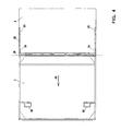
- the transport container as shown in the figures, in particular in the FIG. 1 is shown in a perspective, schematic representation, has a bottom plate 1, a first end wall 2, a second end wall 3, a rear wall 4, a first and a second door 5, 6 and a cover 7.
- the bottom plate 1 has at the bottom in each case in the corners of feet 8 such that the bottom plate 1 is held with a sufficient distance above a floor to accommodate the transport and storage container with a mobile stacker and can settle.
- first door 5 is pivotally connected to a hinge 9 in the direction of the pivot arrow 10 and 11 such that the first door 5 can be placed flat on the inside of the first end wall 2.
- a special hinge arrangement for pivoting the door leaf 5 on the end wall 2 is shown in FIG FIG. 5 and will be explained below.
- FIG. 1 left, second door 6 with the second end wall 3 about a hinge 12 in the direction of the pivot member 13 and pivot 14 so pivotally, that this door 6, corresponding to the door 5, on the inside of the second end wall 3 can be brought to bear.
- the first end wall 2 is pivotable about a hinge 15 in the direction of the pivoting arrow 16 or of the pivoting arrow 17 toward the base plate 1.
- the hinge 18 is located with its axis higher above the bottom plate 1 than the hinge 15 of the first end wall. This is achieved by a corresponding edge strips 21 and 22, which forms part of the respective end wall and is firmly connected to the bottom plate 1.
- the lid 7 is connected to the upper edge of the rear side wall 4 by means of a hinge 26 which can be pivoted in the direction of the pivot arrow 270 outwards by 270 ° so that the lid 7 hangs with its outside on the outside of the rear side wall 4.
- Each door 5, 6 may be associated with a lock, for example, by a pivot arm, which is held in its center and in the middle of the height of the door leaf 5, 6 about a pivot point, and the respective hooked ends of such a pivot arm can in retaining projections, which are assigned to the bottom plate 1 on the one hand and the lid 7 on the other hand, be locked.
- the two pivot arms are in the respective positions, as in FIG. 1 to be seen, panned.
- FIG. 1 a latch is shown in which in the region of the front edge of the lid 7, two lateral locking slide 28 are arranged, which lock on corresponding retaining projections 30 which are fixed to the side walls.
- the two doors 5, 6 are locked at the same time on the lid 7, including, for example, can be provided at the front edge of the lid tabs, which overlap the door 5, 6 outside.
- first door 5 is pivoted to the inside of the first end wall 2.
- end wall 2 is pivoted about the hinge 15 around, with the underlying first door 5, to the bottom plate 1 and placed on the bottom plate 1.
- This arrangement of base plate 1, first door 5 and first end wall 2 is in FIG. 2 to see.
- second door 6 is pivoted to the inside of the second end side wall 3, after which the second end wall 3 is pivoted about the hinge 18 to the bottom plate 1 out.
- the second door leaf 6, which adjoins the second end side wall 3 comes to rest on the first end wall 2, with the second end wall 3 located above it.
- FIG. 3 Now, the bottom plate 1 of the container from the direction of the arrow IIIA in FIG. 1 with the edge strip 23, the folded inward rear wall 4 and the outside of the back wall 4 folded lid 7 shown.
- FIG. 3A It can be seen that with the same dimensions of the width of the bottom plate 1 and the height of the rear wall 4 including the edge strip 23 when the lid 7, which has a width corresponding to the bottom plate 1, folded on the back wall 4 rests, the cover 7 outside protrudes beyond the bottom plate 1. This is because the rear side wall 4, due to the edge strip 23, is shorter than the corresponding dimension of the lid 7.
- the edge strip 23 of the rear side wall 4 is required to the rear side wall 4 in a plane above the two end side walls 3 and 4 with the connected door leaves 5 and 6 to bring, as the FIG. 2 shows and explained above. Since such over the base of the bottom plate 1 protruding cover 7 is not acceptable due to transport and space requirements, the lid 7, relative to the rear wall 4, held displaceable in the direction of arrow 43, in the region of the pivot axis 26, so that the lid 7 can be moved into such a position in which its free edge 31 terminates with the edge of the bottom plate 1 or directly above the edge strip 23. As a result, even in the folded state of the transport container whose Grund perennial feeling, given by the bottom plate 1, not exceeded.
- FIG. 4 an embodiment in which the lid 7 and its hinge 26 is held on a U-shaped bracket 32.
- the two free legs 33 of the U-shaped bracket 32 are in sleeve parts 34 which is fixedly secured to the rear wall 4, out.
- the cover 7 can be moved in the direction of the arrow 43 until the thickened ends of the legs 33 of the bracket 32 at reach the end faces of the sleeves 34 to the plant.
- the displacement of the cover 7 relative to the rear side wall 4 can also be solved in other ways; However, the displacement mechanism should be kept as flat as possible in order not to increase the overall height of the transport container in the folded state too much.
- FIG. 5 the hinge connection 9 between the right, first side wall 2 and the right, first door 5 is shown.
- This hinge connection is formed by a thin tube or rod 35 and a thick tube 36 pushed over it.
- the thin rod 35 is part of the first end wall 2 and is held between an upper bar 37 and a lower bar 38 at its ends. Between the thin rod 35 and the wall plate of the end wall 2, a small gap 39 is left so as not to hinder the rotation of the thick tube 36.
- the door 5 is fixed, so that the door leaf 5 with the guided around thin rod 35 tube 36 is pivotable, as described above with reference to FIG. 1 is explained.
- FIG. 5 the hinge connection 9 between the right, first side wall 2 and the right, first door 5 is shown.
- This hinge connection is formed by a thin tube or rod 35 and a thick tube 36 pushed over it.
- the thin rod 35 is part of the first end wall 2 and is held between an upper bar 37 and a lower bar 38 at its ends.
- a small gap 39 is left so as not to
- the tube 36 is shorter than the rod 35, by a length corresponding to the height of reinforcing plates 40, which stiffen the lower corner portion of the transport container and are fixedly connected to the bottom plate 1.
- locking parts can be provided, which only then release from a corresponding engagement when the door leaf 5, before a pivoting movement, is lifted upwards in the direction of the arrow 41.
- Such locking parts can be provided directly in the region of the reinforcing plates 40, or between the lower edge of the door leaf 5 and the bottom plate. 1
- the cover 7 has a raised edge, or edge parts, designated by the reference numeral 42 has.
- This edge 42 serves as in FIG. 6 is shown, individual transport containers, in particular in their folded state, stacked to arrange so that they can not move to each other. Because of this edge 42 but also both folded transport containers and transport containers that are unfolded, and also filled with objects, can be stacked. Based on FIG. 6 It can also be seen that about three of the folded transport containers occupy the space of an unfolded transport container.
- Essential for the transport container is the principle of how his individual parts can be folded so that they save space, not exceed the basic size, but also in the unfolded state are very stable and especially suitable for being made of metal.
Landscapes
- Engineering & Computer Science (AREA)
- Mechanical Engineering (AREA)
- Rigid Containers With Two Or More Constituent Elements (AREA)
- Polymerisation Methods In General (AREA)
- Vehicle Step Arrangements And Article Storage (AREA)
Claims (29)
- Conteneur de transport et de stockage pour le transport et la mise à disposition d'objets, en particulier des pièces d'accessoires automobiles dans la zone de chaines de montage, qui présente une plaque de sol, une première paroi latérale frontale et une seconde paroi latérale avant opposée, une paroi latérale arrière, une paroi latérale avant opposée à la paroi latérale arrière et un couvercle fixé pivotant opposé à la plaque de fond, le contenu pouvant être réduit en taille à l'état vide dans ses dimensions externes au moins par rabat partiel des parois les unes par rapport aux autres, la plaque de fond et les parois et les parois avec des parois étant reliées par des charnières,
caractérisé en ce que
la paroi latérale avant est divisée en formant un premier et un second battant de porte (5, 6),
en ce que le premier battant de porte (5) est maintenu pivotant avec le bord latéral perpendiculaire de la première paroi frontale (2), de sorte que le premier battant de porte (5) s'applique contre la face interne de la première paroi latérale avant (2),
en ce que la première paroi latérale frontale (2) est maintenue pivotante contre la face frontale associée de la plaque de fond (1) de sorte que cette première paroi latérale frontale (2) est pivotante avec le premier battant de porte (5) reposant dessus par rapport à la plaque de fond (1) de sorte que le premier battant de porte (5) vient s'appliquer contre la plaque de fond (1),
en ce que le second battant de porte (6) est maintenu pivotant avec le bord latéral s'étendant perpendiculairement de la seconde paroi latérale (3) de sorte que ce second battant de porte (6) s'applique sur la face interne de la seconde paroi latérale frontale (3),
en ce que la seconde paroi latérale frontale (3) est maintenue contre la face frontale associée de la plaque de fond (1) de manière pivotante avec l'axe pivotant (18) de manière correspondante au-dessus du plan de la plaque de fond (1) de sorte que cette seconde paroi latérale frontale (3) est pivotante avec le second battant de porte (6) reposant vers l'intérieur en direction de la plaque de fond (1) de sorte que le second battant de porte (6) vient s'appliquer sur la face externe de la première paroi latérale frontale (2),
en ce que le couvercle (7) est maintenu pivotant sur le bord longitudinal supérieur de la paroi latérale arrière (4), en ce que le couvercle (7) vient s'appliquer par sa face externe sur la face externe de la paroi latérale arrière (4),
en ce que la paroi latérale arrière (4) est maintenue contre la face longitudinale associée de la plaque de fond (1) de manière pivotante avec l'axe pivotant (24) en conséquence au-dessus du plan de la plaque de fond (1) de sorte que cette paroi latérale arrière (4) est pivotante avec le couvercle externe (7) par rapport à la plaque de fond (1) de sorte que la face externe de la paroi latérale arrière (4) vient s'appliquer sur la face externe de la seconde paroi latérale frontale (3). - Conteneur de transport et de stockage selon la revendication 1, caractérisé en ce que l'axe pivotant (15) se trouve entre la plaque de fond (1) et la première paroi latérale frontale (2) à une distance au-dessus du plan de la plaque de fond (1) de sorte que le premier battant de porte (5) repose par sa surface sur la plaque de fond (1).
- Conteneur de transport et de stockage selon la revendication 1 ou 2, caractérisé en ce que l'axe pivotant (18) se trouve entre la plaque de fond (1) et la seconde paroi latérale frontale (3) à une distance au-dessus du plan de la plaque de fond (1) qui correspond à peu près à la somme de l'épaisseur de la première paroi latérale frontale (2) et du premier battant de porte (5),
- Conteneur de transport et stockage selon l'une des revendications 1 à 3, caractérisé en ce que l'axe pivotant (24) se trouve entre la plaque de fond (1) et la paroi latérale arrière (4) à une distance au-dessus du plan de la plaque de fond (1) qui correspond à peu près à la somme de l'épaisseur de la première paroi latérale frontale (2) et le premier battant de porte (5) et l'épaisseur de la seconde paroi latérale frontale (3) et du second battant de porte (6).
- Conteneur de transport et de réserve selon l'une des revendications 2 à 4, caractérisé en ce que l'axe pivotant (15) de la première paroi latérale frontale (2) est formé sur le bord supérieur d'une section (21) fixe reliée à la plaque de fond (1) de la première paroi latérale frontale (2).
- Conteneur de transport et de réserve selon l'une des revendications 3 à 5, caractérisé en ce que l'axe pivotant (18) de la seconde paroi latérale frontale (3) est formé sur le bord supérieur d'une section (22) fixe, reliée à la plaque de fond (1) de la seconde paroi latérale frontale (3).
- Conteneur de transport et de réserve selon l'une des revendications 3 à 6, caractérisé en ce que l'axe pivotant (24) de la paroi latérale arrière (4) est formé sur le bord supérieur d'une section fixe (23) de la paroi latérale arrière (4), reliée à la plaque de fond (1).
- Conteneur de transport et de réserve selon l'une des revendications 1 à 7, caractérisé en ce que chaque battant de porte (5, 6) peut être verrouillé à l'état monté du conteneur respectivement avec la plaque de fond (1) d'une part et avec le couvercle (7) d'autre part par au moins un verrouillage.
- Conteneur de transport et de stockage selon la revendication 8, caractérisé en ce que la plaque de fond (1) est serrée contre le couvercle (7) par le verrouillage.
- Conteneur de transport et de stockage selon la revendication 8 ou 9, caractérisé en ce que le verrou est formé par un bras pivotant (28) maintenu pivotant contre le battant de porte (5; 6).
- Conteneur de transport et de stockage selon la revendication 10, caractérisé en ce que le bras pivotant s'engage par ses extrémités dans un ergot de verrouillage sur la plaque de fond (1) et sur le couvercle (7).
- Conteneur de transport et de stockage selon la revendication 10 ou 11, caractérisé en ce que le point de pivotement du bras pivotant est disposé environ à mi-hauteur du battant de porte (5 ; 6).
- Conteneur de transport et de réserve selon l'une des revendications 1 à 12, caractérisé en ce que l'axe pivotant (26) est formé par une charnière correspondante entre la paroi latérale arrière (4) et le couvercle (7), charnière qui est associée au couvercle (7) et cette charnière (26) est maintenue au couvercle (7) dans un dispositif de guidage (32, 33, 34) sur la paroi latérale arrière (4) de sorte que la charnière (26) est placée à distance du bord longitudinal associé de la paroi latérale arrière (4).
- Conteneur de transport et de stockage selon la revendication 13, caractérisée en ce que la distance entre la charnière (26) et le bord associé de la paroi latérale arrière (4) est sélectionnable de sorte que le couvercle (7) puisse être positionné en projection au-dessus de la plaque de fond (1) de manière concordante.
- Conteneur de transport et de stockage selon la revendication 13 ou la revendication 14, caractérisé en ce que le dispositif de guidage (32, 33, 34) est formée par deux barre (33) qui sont guidées respectivement dans une douille (34) associée à la paroi latérale arrière (4).
- Conteneur de transport et de stockage selon la revendication 15, caractérisé en ce que les deux barres (33) sont formées par les extrémités libres d'un étrier en forme de U (32), la partie transversale reliant les deux extrémités (33) de l'étrier en forme de U (32) est associée au couvercle (7).
- Conteneur de transport et de réserve selon l'une des revendications 1 à 16, caractérisé en ce que la connexion pivotante respective (9; 12) est formée entre la première paroi latérale frontale (2) et le premier battant de porte (5) et entre la seconde paroi latérale frontale (3) et le second battant de porte (6) par un dispositif tubulaire (35, 36) avec une section de tube plus épaisse (36) qui est associée au battant de porte (5; 6) et une section tubulaire plus mince (35) qui est associée à la paroi latérale frontale (2; 3).
- Conteneur de transport et de réserve selon l'une des revendications 1 à 17, caractérisé en ce que des plaques de renfort (40) sont disposées dans les zones d'angle de la plaque de fond (1) et les parois latérales frontales (2; 3), de la paroi latérale arrière (4) et/ou des battants de porte (5, 6).
- Conteneur de transport et de stockage selon la revendication 17 et la revendication 18, caractérisé en ce que la section tubulaire plus épaisse (36) présente une longueur qui correspond à la hauteur de u bord latéral du battant de porte (5 ; 6) respectivement de la paroi latérale frontale (2; 3) moins la hauteur de la plaque de renfort (40).
- Conteneur de transport et de stockage selon la revendication 19, caractérisé en ce que pour le basculement du battant de porte (5; 6), le battant de porte (5; 6) peut être soulevé dans le dispositif tubulaire (35, 36) en direction de la face interne de la paroi latérale frontale (2; 3)- de sorte que la face inférieure du battant de porte (5; 6) parvient au-dessus de la plaque de renfort (40).
- Conteneur de transport et de stockage selon la revendication 20, caractérisé en ce qu'avec le soulèvement du battant de porte (5; 6), le battant de porte (5; 6) est libéré du verrouillage.
- Conteneur de transport et de stockage selon la revendication 21, caractérisé en ce que le battant de porte (5; 6) est libéré d'un verrouillage par la plaque de renfort (40).
- Conteneur de transport et de stockage selon la revendication 23, caractérisé en ce que le battant de porte (5; 6) est libéré du verrouillage par la plaque de fond (1).
- Conteneur de transport et de stockage selon la revendication 23, caractérisé en ce que le verrouillage est formé par une broche qui s'engage dans un perçage correspondant.
- Conteneur de transport et de réserve selon l'une des revendications 1 à 24, caractérisé en ce que le couvercle (7) est divisé en eux parties de couvercle dans le sens longitudinal, les deux parties de couvercle étant maintenues pivotantes entre elles par une charnière de sorte qu'une partie de couvercle est pivotante sur l'autre partie de couvercle.
- Conteneur de transport et de réserve selon l'une des revendications 1 à 25, caractérisé en ce que sur la face inférieure de la plaque de fond (1) sont réalisées des parties de pied (8) qui s'appliquent sur la face interne d'un bord (42) réalisé sur la face externe du couvercle (7) pur des conteneurs superposés.
- Conteneur de transport et de réserve selon l'une des revendications 1 à 26, caractérisé en ce qu'au moins la plaque de fond (1), les parois latérales frontales (2; 3), la paroi latérale arrière (4) et le couvercle (7) sont réalisés à partir de plaques métalliques.
- Conteneur de transport et de réserve selon l'une des revendications 1 à 7, caractérisé en ce que le cercle (7) présente des verrouillages (28) à l'état monté qui sont verrouillables sur les parois latérales frontales (2, 3).
- Conteneur de transport et de stockage selon la revendication 28, caractérisé en ce que le battant de porte (5, 6) est verrouillé avec le couvercle (7).
Applications Claiming Priority (2)
| Application Number | Priority Date | Filing Date | Title |
|---|---|---|---|
| DE102004060400A DE102004060400A1 (de) | 2004-12-14 | 2004-12-14 | Transport- und Vorratsbehälter |
| PCT/EP2005/013325 WO2006063775A1 (fr) | 2004-12-14 | 2005-12-13 | Conteneur de transport et de stockage repliable |
Publications (2)
| Publication Number | Publication Date |
|---|---|
| EP1824747A1 EP1824747A1 (fr) | 2007-08-29 |
| EP1824747B1 true EP1824747B1 (fr) | 2008-10-01 |
Family
ID=35840662
Family Applications (1)
| Application Number | Title | Priority Date | Filing Date |
|---|---|---|---|
| EP05824662A Not-in-force EP1824747B1 (fr) | 2004-12-14 | 2005-12-13 | Conteneur de transport et de stockage repliable |
Country Status (5)
| Country | Link |
|---|---|
| US (1) | US20080190810A1 (fr) |
| EP (1) | EP1824747B1 (fr) |
| AT (1) | ATE409653T1 (fr) |
| DE (2) | DE102004060400A1 (fr) |
| WO (1) | WO2006063775A1 (fr) |
Families Citing this family (8)
| Publication number | Priority date | Publication date | Assignee | Title |
|---|---|---|---|---|
| DE102007021813A1 (de) | 2007-05-07 | 2008-11-13 | Manfred Steigerwald | Transport- und Vorratsbehälter |
| DE202007015661U1 (de) | 2007-11-08 | 2009-03-19 | Steigerwald, Manfred | Transport- und Vorratsbehälter |
| KR100987869B1 (ko) * | 2010-03-11 | 2010-10-13 | 현기훈 | 접철식 컨테이너형 파레트 |
| USD789648S1 (en) * | 2015-12-04 | 2017-06-13 | Lane J. Segerstrom | Maintainable pallet |
| US10118732B2 (en) | 2016-12-09 | 2018-11-06 | Lane Segerstrom | Maintainable pallet |
| KR102079642B1 (ko) * | 2018-02-26 | 2020-02-20 | 김경조 | 적재대 |
| DK180580B1 (en) * | 2020-01-06 | 2021-09-06 | Maersk As | A collapsible rack for supporting carcasses inside refrigerated inter- modal containers and a method for collapsing such rack |
| PL3974335T3 (pl) * | 2020-09-23 | 2023-06-05 | Schneider Transport- und Lagerbehälter GmbH & Co. KG | Ładunkowa konstrukcja nośna |
Family Cites Families (8)
| Publication number | Priority date | Publication date | Assignee | Title |
|---|---|---|---|---|
| US13321A (en) * | 1855-07-24 | Hinge | ||
| FR2186393B1 (fr) * | 1972-05-31 | 1976-10-29 | Reunis Sa Ateliers | |
| IT1084787B (it) * | 1977-09-30 | 1985-05-28 | Euteco Spa | Contenitore ripiegabile perfezionato |
| US4240555A (en) * | 1978-12-22 | 1980-12-23 | Eagle-Picher Industries, Inc. | Collapsible material handling container |
| JPH03502568A (ja) * | 1988-05-17 | 1991-06-13 | リーズ オペレーションズ ピーティーワイ リミテッド | 折畳み式パレット箱 |
| PL348676A1 (en) * | 1998-11-25 | 2002-06-03 | Carrimor Aps | Collapsible container for transporting a liquid |
| US6811048B2 (en) * | 2002-02-12 | 2004-11-02 | David M. K. Lau | Fold-up storage container |
| JP3979638B2 (ja) * | 2002-07-05 | 2007-09-19 | 株式会社リコー | 物品運搬保管装置 |
-
2004
- 2004-12-14 DE DE102004060400A patent/DE102004060400A1/de not_active Withdrawn
-
2005
- 2005-12-13 DE DE502005005569T patent/DE502005005569D1/de active Active
- 2005-12-13 AT AT05824662T patent/ATE409653T1/de not_active IP Right Cessation
- 2005-12-13 US US11/792,870 patent/US20080190810A1/en not_active Abandoned
- 2005-12-13 EP EP05824662A patent/EP1824747B1/fr not_active Not-in-force
- 2005-12-13 WO PCT/EP2005/013325 patent/WO2006063775A1/fr active IP Right Grant
Also Published As
| Publication number | Publication date |
|---|---|
| EP1824747A1 (fr) | 2007-08-29 |
| US20080190810A1 (en) | 2008-08-14 |
| DE502005005569D1 (de) | 2008-11-13 |
| DE102004060400A1 (de) | 2006-07-06 |
| WO2006063775A1 (fr) | 2006-06-22 |
| ATE409653T1 (de) | 2008-10-15 |
Similar Documents
| Publication | Publication Date | Title |
|---|---|---|
| EP1824747B1 (fr) | Conteneur de transport et de stockage repliable | |
| DE2546645C2 (de) | Zusammenlegbarer Behälter | |
| EP2575436B1 (fr) | Boîte de transport pour animaux ou pour objets, prévue notamment pour encastrement dans des véhicules | |
| EP2840045B1 (fr) | Récipient de transport pour marchandises au détail | |
| DE2924105A1 (de) | Rollbehaelter | |
| DE3010366A1 (de) | Rollbehaelter mit schwenkbaren seitenwaenden und mit im bereich der schwenkbaren enden derselben getragenen schwenkbaren laufrollen | |
| DE2740818A1 (de) | Stapelbare last- oder rollpalette | |
| EP3599142B1 (fr) | Conteneur roulant | |
| DE202006004351U1 (de) | Palettenbügel für eine Euro-Palette | |
| DE3633348A1 (de) | Zusammenlegbarer transportbehaelter fuer stueckgueter | |
| DE202020100095U1 (de) | Rollwagen zum Transport von insbesondere Wäsche und/oder Wäschesäcken | |
| DE202020105201U1 (de) | Rollbehälter | |
| EP2428434B1 (fr) | Mécanisme de fermeture pour une structure de véhicule | |
| DE4135677A1 (de) | Ladungstraeger | |
| DE1807388A1 (de) | Container mit abnehmbarem Dach | |
| DE2557751C3 (de) | Gelenkverbindung, insbesondere an einer Transportpalette | |
| EP2025611B1 (fr) | Unité d'articulation pour les montants d'un châssis de transport ou de stockage pliant | |
| DE3220859C2 (de) | Langgut-Container | |
| DE2547436A1 (de) | Zusammenlegbarer transportbehaelter | |
| DE10349656B4 (de) | Palette zum Transportieren von übereinander gestapelten Gegenständen | |
| EP3363748A1 (fr) | Récipient empilable et emboitable | |
| AT521000B1 (de) | Zusammenlegbare Transportvorrichtung | |
| DE202015103235U1 (de) | Zusammenklappbarer Behälter | |
| DE3100787C2 (de) | Transportwagen | |
| DE4405289C1 (de) | Arbeitsbühne |
Legal Events
| Date | Code | Title | Description |
|---|---|---|---|
| PUAI | Public reference made under article 153(3) epc to a published international application that has entered the european phase |
Free format text: ORIGINAL CODE: 0009012 |
|
| 17P | Request for examination filed |
Effective date: 20070523 |
|
| AK | Designated contracting states |
Kind code of ref document: A1 Designated state(s): AT BE BG CH CY CZ DE DK EE ES FI FR GB GR HU IE IS IT LI LT LU LV MC NL PL PT RO SE SI SK TR |
|
| DAX | Request for extension of the european patent (deleted) | ||
| GRAP | Despatch of communication of intention to grant a patent |
Free format text: ORIGINAL CODE: EPIDOSNIGR1 |
|
| GRAS | Grant fee paid |
Free format text: ORIGINAL CODE: EPIDOSNIGR3 |
|
| GRAA | (expected) grant |
Free format text: ORIGINAL CODE: 0009210 |
|
| AK | Designated contracting states |
Kind code of ref document: B1 Designated state(s): AT BE BG CH CY CZ DE DK EE ES FI FR GB GR HU IE IS IT LI LT LU LV MC NL PL PT RO SE SI SK TR |
|
| REG | Reference to a national code |
Ref country code: GB Ref legal event code: FG4D Free format text: NOT ENGLISH |
|
| REG | Reference to a national code |
Ref country code: CH Ref legal event code: EP |
|
| REG | Reference to a national code |
Ref country code: IE Ref legal event code: FG4D Free format text: LANGUAGE OF EP DOCUMENT: GERMAN |
|
| REF | Corresponds to: |
Ref document number: 502005005569 Country of ref document: DE Date of ref document: 20081113 Kind code of ref document: P |
|
| PG25 | Lapsed in a contracting state [announced via postgrant information from national office to epo] |
Ref country code: SI Free format text: LAPSE BECAUSE OF FAILURE TO SUBMIT A TRANSLATION OF THE DESCRIPTION OR TO PAY THE FEE WITHIN THE PRESCRIBED TIME-LIMIT Effective date: 20081001 |
|
| NLV1 | Nl: lapsed or annulled due to failure to fulfill the requirements of art. 29p and 29m of the patents act | ||
| REG | Reference to a national code |
Ref country code: IE Ref legal event code: FD4D |
|
| PG25 | Lapsed in a contracting state [announced via postgrant information from national office to epo] |
Ref country code: BG Free format text: LAPSE BECAUSE OF FAILURE TO SUBMIT A TRANSLATION OF THE DESCRIPTION OR TO PAY THE FEE WITHIN THE PRESCRIBED TIME-LIMIT Effective date: 20090101 Ref country code: ES Free format text: LAPSE BECAUSE OF FAILURE TO SUBMIT A TRANSLATION OF THE DESCRIPTION OR TO PAY THE FEE WITHIN THE PRESCRIBED TIME-LIMIT Effective date: 20090112 Ref country code: LT Free format text: LAPSE BECAUSE OF FAILURE TO SUBMIT A TRANSLATION OF THE DESCRIPTION OR TO PAY THE FEE WITHIN THE PRESCRIBED TIME-LIMIT Effective date: 20081001 |
|
| PG25 | Lapsed in a contracting state [announced via postgrant information from national office to epo] |
Ref country code: NL Free format text: LAPSE BECAUSE OF FAILURE TO SUBMIT A TRANSLATION OF THE DESCRIPTION OR TO PAY THE FEE WITHIN THE PRESCRIBED TIME-LIMIT Effective date: 20081001 Ref country code: FI Free format text: LAPSE BECAUSE OF FAILURE TO SUBMIT A TRANSLATION OF THE DESCRIPTION OR TO PAY THE FEE WITHIN THE PRESCRIBED TIME-LIMIT Effective date: 20081001 Ref country code: PL Free format text: LAPSE BECAUSE OF FAILURE TO SUBMIT A TRANSLATION OF THE DESCRIPTION OR TO PAY THE FEE WITHIN THE PRESCRIBED TIME-LIMIT Effective date: 20081001 Ref country code: PT Free format text: LAPSE BECAUSE OF FAILURE TO SUBMIT A TRANSLATION OF THE DESCRIPTION OR TO PAY THE FEE WITHIN THE PRESCRIBED TIME-LIMIT Effective date: 20090302 Ref country code: IS Free format text: LAPSE BECAUSE OF FAILURE TO SUBMIT A TRANSLATION OF THE DESCRIPTION OR TO PAY THE FEE WITHIN THE PRESCRIBED TIME-LIMIT Effective date: 20090201 Ref country code: LV Free format text: LAPSE BECAUSE OF FAILURE TO SUBMIT A TRANSLATION OF THE DESCRIPTION OR TO PAY THE FEE WITHIN THE PRESCRIBED TIME-LIMIT Effective date: 20081001 |
|
| BERE | Be: lapsed |
Owner name: STEIGERWALD, MANFRED Effective date: 20081231 |
|
| PG25 | Lapsed in a contracting state [announced via postgrant information from national office to epo] |
Ref country code: RO Free format text: LAPSE BECAUSE OF FAILURE TO SUBMIT A TRANSLATION OF THE DESCRIPTION OR TO PAY THE FEE WITHIN THE PRESCRIBED TIME-LIMIT Effective date: 20081001 Ref country code: MC Free format text: LAPSE BECAUSE OF NON-PAYMENT OF DUE FEES Effective date: 20081231 Ref country code: IE Free format text: LAPSE BECAUSE OF FAILURE TO SUBMIT A TRANSLATION OF THE DESCRIPTION OR TO PAY THE FEE WITHIN THE PRESCRIBED TIME-LIMIT Effective date: 20081001 Ref country code: EE Free format text: LAPSE BECAUSE OF FAILURE TO SUBMIT A TRANSLATION OF THE DESCRIPTION OR TO PAY THE FEE WITHIN THE PRESCRIBED TIME-LIMIT Effective date: 20081001 Ref country code: DK Free format text: LAPSE BECAUSE OF FAILURE TO SUBMIT A TRANSLATION OF THE DESCRIPTION OR TO PAY THE FEE WITHIN THE PRESCRIBED TIME-LIMIT Effective date: 20081001 |
|
| PLBE | No opposition filed within time limit |
Free format text: ORIGINAL CODE: 0009261 |
|
| STAA | Information on the status of an ep patent application or granted ep patent |
Free format text: STATUS: NO OPPOSITION FILED WITHIN TIME LIMIT |
|
| PG25 | Lapsed in a contracting state [announced via postgrant information from national office to epo] |
Ref country code: CZ Free format text: LAPSE BECAUSE OF FAILURE TO SUBMIT A TRANSLATION OF THE DESCRIPTION OR TO PAY THE FEE WITHIN THE PRESCRIBED TIME-LIMIT Effective date: 20081001 Ref country code: IT Free format text: LAPSE BECAUSE OF FAILURE TO SUBMIT A TRANSLATION OF THE DESCRIPTION OR TO PAY THE FEE WITHIN THE PRESCRIBED TIME-LIMIT Effective date: 20081001 Ref country code: SE Free format text: LAPSE BECAUSE OF FAILURE TO SUBMIT A TRANSLATION OF THE DESCRIPTION OR TO PAY THE FEE WITHIN THE PRESCRIBED TIME-LIMIT Effective date: 20090101 |
|
| 26N | No opposition filed |
Effective date: 20090702 |
|
| PG25 | Lapsed in a contracting state [announced via postgrant information from national office to epo] |
Ref country code: BE Free format text: LAPSE BECAUSE OF NON-PAYMENT OF DUE FEES Effective date: 20081231 Ref country code: SK Free format text: LAPSE BECAUSE OF FAILURE TO SUBMIT A TRANSLATION OF THE DESCRIPTION OR TO PAY THE FEE WITHIN THE PRESCRIBED TIME-LIMIT Effective date: 20081001 |
|
| PGFP | Annual fee paid to national office [announced via postgrant information from national office to epo] |
Ref country code: FR Payment date: 20100108 Year of fee payment: 5 |
|
| PG25 | Lapsed in a contracting state [announced via postgrant information from national office to epo] |
Ref country code: AT Free format text: LAPSE BECAUSE OF NON-PAYMENT OF DUE FEES Effective date: 20081213 |
|
| PG25 | Lapsed in a contracting state [announced via postgrant information from national office to epo] |
Ref country code: CY Free format text: LAPSE BECAUSE OF FAILURE TO SUBMIT A TRANSLATION OF THE DESCRIPTION OR TO PAY THE FEE WITHIN THE PRESCRIBED TIME-LIMIT Effective date: 20081001 Ref country code: HU Free format text: LAPSE BECAUSE OF FAILURE TO SUBMIT A TRANSLATION OF THE DESCRIPTION OR TO PAY THE FEE WITHIN THE PRESCRIBED TIME-LIMIT Effective date: 20090402 Ref country code: LU Free format text: LAPSE BECAUSE OF NON-PAYMENT OF DUE FEES Effective date: 20081213 |
|
| REG | Reference to a national code |
Ref country code: CH Ref legal event code: PL |
|
| GBPC | Gb: european patent ceased through non-payment of renewal fee |
Effective date: 20091213 |
|
| PG25 | Lapsed in a contracting state [announced via postgrant information from national office to epo] |
Ref country code: CH Free format text: LAPSE BECAUSE OF NON-PAYMENT OF DUE FEES Effective date: 20091231 Ref country code: GR Free format text: LAPSE BECAUSE OF FAILURE TO SUBMIT A TRANSLATION OF THE DESCRIPTION OR TO PAY THE FEE WITHIN THE PRESCRIBED TIME-LIMIT Effective date: 20090102 Ref country code: LI Free format text: LAPSE BECAUSE OF NON-PAYMENT OF DUE FEES Effective date: 20091231 |
|
| PG25 | Lapsed in a contracting state [announced via postgrant information from national office to epo] |
Ref country code: GB Free format text: LAPSE BECAUSE OF NON-PAYMENT OF DUE FEES Effective date: 20091213 |
|
| PGFP | Annual fee paid to national office [announced via postgrant information from national office to epo] |
Ref country code: TR Payment date: 20110112 Year of fee payment: 6 |
|
| REG | Reference to a national code |
Ref country code: FR Ref legal event code: ST Effective date: 20110831 |
|
| PG25 | Lapsed in a contracting state [announced via postgrant information from national office to epo] |
Ref country code: FR Free format text: LAPSE BECAUSE OF NON-PAYMENT OF DUE FEES Effective date: 20110103 |
|
| PG25 | Lapsed in a contracting state [announced via postgrant information from national office to epo] |
Ref country code: TR Free format text: LAPSE BECAUSE OF NON-PAYMENT OF DUE FEES Effective date: 20121213 |
|
| PGFP | Annual fee paid to national office [announced via postgrant information from national office to epo] |
Ref country code: DE Payment date: 20150112 Year of fee payment: 10 |
|
| REG | Reference to a national code |
Ref country code: DE Ref legal event code: R119 Ref document number: 502005005569 Country of ref document: DE |
|
| PG25 | Lapsed in a contracting state [announced via postgrant information from national office to epo] |
Ref country code: DE Free format text: LAPSE BECAUSE OF NON-PAYMENT OF DUE FEES Effective date: 20160701 |