EP1824747B1 - Collapsible transport and storage container - Google Patents
Collapsible transport and storage container Download PDFInfo
- Publication number
- EP1824747B1 EP1824747B1 EP05824662A EP05824662A EP1824747B1 EP 1824747 B1 EP1824747 B1 EP 1824747B1 EP 05824662 A EP05824662 A EP 05824662A EP 05824662 A EP05824662 A EP 05824662A EP 1824747 B1 EP1824747 B1 EP 1824747B1
- Authority
- EP
- European Patent Office
- Prior art keywords
- transport
- door leaf
- storage container
- base plate
- container according
- Prior art date
- Legal status (The legal status is an assumption and is not a legal conclusion. Google has not performed a legal analysis and makes no representation as to the accuracy of the status listed.)
- Not-in-force
Links
Images


Classifications
-
- B—PERFORMING OPERATIONS; TRANSPORTING
- B65—CONVEYING; PACKING; STORING; HANDLING THIN OR FILAMENTARY MATERIAL
- B65D—CONTAINERS FOR STORAGE OR TRANSPORT OF ARTICLES OR MATERIALS, e.g. BAGS, BARRELS, BOTTLES, BOXES, CANS, CARTONS, CRATES, DRUMS, JARS, TANKS, HOPPERS, FORWARDING CONTAINERS; ACCESSORIES, CLOSURES, OR FITTINGS THEREFOR; PACKAGING ELEMENTS; PACKAGES
- B65D19/00—Pallets or like platforms, with or without side walls, for supporting loads to be lifted or lowered
- B65D19/02—Rigid pallets with side walls, e.g. box pallets
- B65D19/06—Rigid pallets with side walls, e.g. box pallets with bodies formed by uniting or interconnecting two or more components
- B65D19/08—Rigid pallets with side walls, e.g. box pallets with bodies formed by uniting or interconnecting two or more components made wholly or mainly of metal
- B65D19/12—Collapsible pallets
-
- B—PERFORMING OPERATIONS; TRANSPORTING
- B65—CONVEYING; PACKING; STORING; HANDLING THIN OR FILAMENTARY MATERIAL
- B65D—CONTAINERS FOR STORAGE OR TRANSPORT OF ARTICLES OR MATERIALS, e.g. BAGS, BARRELS, BOTTLES, BOXES, CANS, CARTONS, CRATES, DRUMS, JARS, TANKS, HOPPERS, FORWARDING CONTAINERS; ACCESSORIES, CLOSURES, OR FITTINGS THEREFOR; PACKAGING ELEMENTS; PACKAGES
- B65D2519/00—Pallets or like platforms, with or without side walls, for supporting loads to be lifted or lowered
- B65D2519/00004—Details relating to pallets
- B65D2519/00009—Materials
- B65D2519/00014—Materials for the load supporting surface
- B65D2519/00024—Metal
-
- B—PERFORMING OPERATIONS; TRANSPORTING
- B65—CONVEYING; PACKING; STORING; HANDLING THIN OR FILAMENTARY MATERIAL
- B65D—CONTAINERS FOR STORAGE OR TRANSPORT OF ARTICLES OR MATERIALS, e.g. BAGS, BARRELS, BOTTLES, BOXES, CANS, CARTONS, CRATES, DRUMS, JARS, TANKS, HOPPERS, FORWARDING CONTAINERS; ACCESSORIES, CLOSURES, OR FITTINGS THEREFOR; PACKAGING ELEMENTS; PACKAGES
- B65D2519/00—Pallets or like platforms, with or without side walls, for supporting loads to be lifted or lowered
- B65D2519/00004—Details relating to pallets
- B65D2519/00009—Materials
- B65D2519/00049—Materials for the base surface
- B65D2519/00059—Metal
-
- B—PERFORMING OPERATIONS; TRANSPORTING
- B65—CONVEYING; PACKING; STORING; HANDLING THIN OR FILAMENTARY MATERIAL
- B65D—CONTAINERS FOR STORAGE OR TRANSPORT OF ARTICLES OR MATERIALS, e.g. BAGS, BARRELS, BOTTLES, BOXES, CANS, CARTONS, CRATES, DRUMS, JARS, TANKS, HOPPERS, FORWARDING CONTAINERS; ACCESSORIES, CLOSURES, OR FITTINGS THEREFOR; PACKAGING ELEMENTS; PACKAGES
- B65D2519/00—Pallets or like platforms, with or without side walls, for supporting loads to be lifted or lowered
- B65D2519/00004—Details relating to pallets
- B65D2519/00009—Materials
- B65D2519/00119—Materials for the construction of the reinforcements
- B65D2519/00129—Metal
-
- B—PERFORMING OPERATIONS; TRANSPORTING
- B65—CONVEYING; PACKING; STORING; HANDLING THIN OR FILAMENTARY MATERIAL
- B65D—CONTAINERS FOR STORAGE OR TRANSPORT OF ARTICLES OR MATERIALS, e.g. BAGS, BARRELS, BOTTLES, BOXES, CANS, CARTONS, CRATES, DRUMS, JARS, TANKS, HOPPERS, FORWARDING CONTAINERS; ACCESSORIES, CLOSURES, OR FITTINGS THEREFOR; PACKAGING ELEMENTS; PACKAGES
- B65D2519/00—Pallets or like platforms, with or without side walls, for supporting loads to be lifted or lowered
- B65D2519/00004—Details relating to pallets
- B65D2519/00009—Materials
- B65D2519/00154—Materials for the side walls
- B65D2519/00164—Metal
-
- B—PERFORMING OPERATIONS; TRANSPORTING
- B65—CONVEYING; PACKING; STORING; HANDLING THIN OR FILAMENTARY MATERIAL
- B65D—CONTAINERS FOR STORAGE OR TRANSPORT OF ARTICLES OR MATERIALS, e.g. BAGS, BARRELS, BOTTLES, BOXES, CANS, CARTONS, CRATES, DRUMS, JARS, TANKS, HOPPERS, FORWARDING CONTAINERS; ACCESSORIES, CLOSURES, OR FITTINGS THEREFOR; PACKAGING ELEMENTS; PACKAGES
- B65D2519/00—Pallets or like platforms, with or without side walls, for supporting loads to be lifted or lowered
- B65D2519/00004—Details relating to pallets
- B65D2519/00009—Materials
- B65D2519/00189—Materials for the lid or cover
- B65D2519/00199—Metal
-
- B—PERFORMING OPERATIONS; TRANSPORTING
- B65—CONVEYING; PACKING; STORING; HANDLING THIN OR FILAMENTARY MATERIAL
- B65D—CONTAINERS FOR STORAGE OR TRANSPORT OF ARTICLES OR MATERIALS, e.g. BAGS, BARRELS, BOTTLES, BOXES, CANS, CARTONS, CRATES, DRUMS, JARS, TANKS, HOPPERS, FORWARDING CONTAINERS; ACCESSORIES, CLOSURES, OR FITTINGS THEREFOR; PACKAGING ELEMENTS; PACKAGES
- B65D2519/00—Pallets or like platforms, with or without side walls, for supporting loads to be lifted or lowered
- B65D2519/00004—Details relating to pallets
- B65D2519/00009—Materials
- B65D2519/00223—Materials for the corner elements or corner frames
- B65D2519/00233—Metal
-
- B—PERFORMING OPERATIONS; TRANSPORTING
- B65—CONVEYING; PACKING; STORING; HANDLING THIN OR FILAMENTARY MATERIAL
- B65D—CONTAINERS FOR STORAGE OR TRANSPORT OF ARTICLES OR MATERIALS, e.g. BAGS, BARRELS, BOTTLES, BOXES, CANS, CARTONS, CRATES, DRUMS, JARS, TANKS, HOPPERS, FORWARDING CONTAINERS; ACCESSORIES, CLOSURES, OR FITTINGS THEREFOR; PACKAGING ELEMENTS; PACKAGES
- B65D2519/00—Pallets or like platforms, with or without side walls, for supporting loads to be lifted or lowered
- B65D2519/00004—Details relating to pallets
- B65D2519/00258—Overall construction
- B65D2519/00263—Overall construction of the pallet
- B65D2519/00273—Overall construction of the pallet made of more than one piece
-
- B—PERFORMING OPERATIONS; TRANSPORTING
- B65—CONVEYING; PACKING; STORING; HANDLING THIN OR FILAMENTARY MATERIAL
- B65D—CONTAINERS FOR STORAGE OR TRANSPORT OF ARTICLES OR MATERIALS, e.g. BAGS, BARRELS, BOTTLES, BOXES, CANS, CARTONS, CRATES, DRUMS, JARS, TANKS, HOPPERS, FORWARDING CONTAINERS; ACCESSORIES, CLOSURES, OR FITTINGS THEREFOR; PACKAGING ELEMENTS; PACKAGES
- B65D2519/00—Pallets or like platforms, with or without side walls, for supporting loads to be lifted or lowered
- B65D2519/00004—Details relating to pallets
- B65D2519/00258—Overall construction
- B65D2519/00263—Overall construction of the pallet
- B65D2519/00278—Overall construction of the pallet the load supporting surface and the base surface being identical
-
- B—PERFORMING OPERATIONS; TRANSPORTING
- B65—CONVEYING; PACKING; STORING; HANDLING THIN OR FILAMENTARY MATERIAL
- B65D—CONTAINERS FOR STORAGE OR TRANSPORT OF ARTICLES OR MATERIALS, e.g. BAGS, BARRELS, BOTTLES, BOXES, CANS, CARTONS, CRATES, DRUMS, JARS, TANKS, HOPPERS, FORWARDING CONTAINERS; ACCESSORIES, CLOSURES, OR FITTINGS THEREFOR; PACKAGING ELEMENTS; PACKAGES
- B65D2519/00—Pallets or like platforms, with or without side walls, for supporting loads to be lifted or lowered
- B65D2519/00004—Details relating to pallets
- B65D2519/00258—Overall construction
- B65D2519/00313—Overall construction of the base surface
- B65D2519/00318—Overall construction of the base surface made of one piece
-
- B—PERFORMING OPERATIONS; TRANSPORTING
- B65—CONVEYING; PACKING; STORING; HANDLING THIN OR FILAMENTARY MATERIAL
- B65D—CONTAINERS FOR STORAGE OR TRANSPORT OF ARTICLES OR MATERIALS, e.g. BAGS, BARRELS, BOTTLES, BOXES, CANS, CARTONS, CRATES, DRUMS, JARS, TANKS, HOPPERS, FORWARDING CONTAINERS; ACCESSORIES, CLOSURES, OR FITTINGS THEREFOR; PACKAGING ELEMENTS; PACKAGES
- B65D2519/00—Pallets or like platforms, with or without side walls, for supporting loads to be lifted or lowered
- B65D2519/00004—Details relating to pallets
- B65D2519/00258—Overall construction
- B65D2519/00398—Overall construction reinforcements
- B65D2519/00432—Non-integral, e.g. inserts
- B65D2519/00452—Non-integral, e.g. inserts on the walls
-
- B—PERFORMING OPERATIONS; TRANSPORTING
- B65—CONVEYING; PACKING; STORING; HANDLING THIN OR FILAMENTARY MATERIAL
- B65D—CONTAINERS FOR STORAGE OR TRANSPORT OF ARTICLES OR MATERIALS, e.g. BAGS, BARRELS, BOTTLES, BOXES, CANS, CARTONS, CRATES, DRUMS, JARS, TANKS, HOPPERS, FORWARDING CONTAINERS; ACCESSORIES, CLOSURES, OR FITTINGS THEREFOR; PACKAGING ELEMENTS; PACKAGES
- B65D2519/00—Pallets or like platforms, with or without side walls, for supporting loads to be lifted or lowered
- B65D2519/00004—Details relating to pallets
- B65D2519/00258—Overall construction
- B65D2519/00492—Overall construction of the side walls
- B65D2519/00497—Overall construction of the side walls whereby at least one side wall is made of one piece
-
- B—PERFORMING OPERATIONS; TRANSPORTING
- B65—CONVEYING; PACKING; STORING; HANDLING THIN OR FILAMENTARY MATERIAL
- B65D—CONTAINERS FOR STORAGE OR TRANSPORT OF ARTICLES OR MATERIALS, e.g. BAGS, BARRELS, BOTTLES, BOXES, CANS, CARTONS, CRATES, DRUMS, JARS, TANKS, HOPPERS, FORWARDING CONTAINERS; ACCESSORIES, CLOSURES, OR FITTINGS THEREFOR; PACKAGING ELEMENTS; PACKAGES
- B65D2519/00—Pallets or like platforms, with or without side walls, for supporting loads to be lifted or lowered
- B65D2519/00004—Details relating to pallets
- B65D2519/00258—Overall construction
- B65D2519/00492—Overall construction of the side walls
- B65D2519/00502—Overall construction of the side walls whereby at least one side wall is made of two or more pieces
-
- B—PERFORMING OPERATIONS; TRANSPORTING
- B65—CONVEYING; PACKING; STORING; HANDLING THIN OR FILAMENTARY MATERIAL
- B65D—CONTAINERS FOR STORAGE OR TRANSPORT OF ARTICLES OR MATERIALS, e.g. BAGS, BARRELS, BOTTLES, BOXES, CANS, CARTONS, CRATES, DRUMS, JARS, TANKS, HOPPERS, FORWARDING CONTAINERS; ACCESSORIES, CLOSURES, OR FITTINGS THEREFOR; PACKAGING ELEMENTS; PACKAGES
- B65D2519/00—Pallets or like platforms, with or without side walls, for supporting loads to be lifted or lowered
- B65D2519/00004—Details relating to pallets
- B65D2519/00547—Connections
- B65D2519/00636—Connections structures connecting side walls to the pallet
- B65D2519/00641—Structures intended to be disassembled
- B65D2519/00646—Structures intended to be disassembled by means of hinges
- B65D2519/00656—Structures intended to be disassembled by means of hinges separately formed
-
- B—PERFORMING OPERATIONS; TRANSPORTING
- B65—CONVEYING; PACKING; STORING; HANDLING THIN OR FILAMENTARY MATERIAL
- B65D—CONTAINERS FOR STORAGE OR TRANSPORT OF ARTICLES OR MATERIALS, e.g. BAGS, BARRELS, BOTTLES, BOXES, CANS, CARTONS, CRATES, DRUMS, JARS, TANKS, HOPPERS, FORWARDING CONTAINERS; ACCESSORIES, CLOSURES, OR FITTINGS THEREFOR; PACKAGING ELEMENTS; PACKAGES
- B65D2519/00—Pallets or like platforms, with or without side walls, for supporting loads to be lifted or lowered
- B65D2519/00004—Details relating to pallets
- B65D2519/00547—Connections
- B65D2519/00706—Connections structures connecting the lid or cover to the side walls or corner posts
- B65D2519/00716—Connections structures connecting the lid or cover to the side walls or corner posts non-removable lid or covers
- B65D2519/00721—Connections structures connecting the lid or cover to the side walls or corner posts non-removable lid or covers hinged lids
- B65D2519/00731—Connections structures connecting the lid or cover to the side walls or corner posts non-removable lid or covers hinged lids separately formed
-
- B—PERFORMING OPERATIONS; TRANSPORTING
- B65—CONVEYING; PACKING; STORING; HANDLING THIN OR FILAMENTARY MATERIAL
- B65D—CONTAINERS FOR STORAGE OR TRANSPORT OF ARTICLES OR MATERIALS, e.g. BAGS, BARRELS, BOTTLES, BOXES, CANS, CARTONS, CRATES, DRUMS, JARS, TANKS, HOPPERS, FORWARDING CONTAINERS; ACCESSORIES, CLOSURES, OR FITTINGS THEREFOR; PACKAGING ELEMENTS; PACKAGES
- B65D2519/00—Pallets or like platforms, with or without side walls, for supporting loads to be lifted or lowered
- B65D2519/00004—Details relating to pallets
- B65D2519/00736—Details
- B65D2519/00865—Collapsible, i.e. at least two constitutive elements remaining hingedly connected
- B65D2519/00875—Collapsible, i.e. at least two constitutive elements remaining hingedly connected collapsible side walls
Definitions
- the present invention relates to a transport and storage container for transporting and providing objects, in particular of motor vehicle accessories in the range of mounting bands, a bottom plate, a first end wall and an opposite second end wall, a rear wall, a rear wall opposite the front wall and a bottom plate opposite , pivotally mounted lid, wherein the container in the empty state in its outer dimensions by at least partially pivoting the walls is reduced to each other, including bottom plate and walls and walls are connected to walls by hinges.
- Transport containers are used in a variety of ways to transport a wide variety of items.
- such transport containers are used in the automotive industry to transport accessories, assemblies or other parts necessary for mounting a vehicle from the supplier to the automobile manufacturer.
- transport containers must be very stable, so that the transported parts are not damaged.
- the transport containers must also be reusable in order to use them repeatedly for the intended transport. For this reason, such containers are usually made of metal, whereby they have a significant weight.
- the empty transport and storage containers can be reduced in their outer dimensions, i. they must be disassembled or folded, but at the same time they must not exceed the given basic surface dimension, even when folded or folded.
- a front wall can also be opened so that the parts provided in the container can be removed on the assembly line.
- these containers must be stackable so that several containers can be placed one above the other during assembly in order then to be able to remove the parts via the respective open front side walls.
- the present invention seeks to provide a transport and storage container of the type described in such a way that a secure transport of the items is guaranteed in that a simple removal of objects is made possible and that the container can be transported in a space-saving manner even when empty, without having to handle a large number of individual parts.
- a transport and storage container having both a lid and front door, so that the corresponding parts to be stowed in the container introduced from above the lid and on the front door opening into the container or taken out of this can be.
- all parts, i. the bottom plate, the end walls, the rear wall and the lid and the door leaves are also connected in the folded state, via corresponding hinges. There are no items to handle, either when unfolding the transport and storage container still when folding the container.
- the container is designed in its construction, that it can be made in particular of stable materials, such as metal, but still has a relatively low weight, despite high stability, by the structure according to the invention.
- the pivot axis should lie between the bottom plate and the first end wall at a corresponding distance above the plane of the bottom plate.
- pivot axis should lie between the bottom plate and the second end wall at a distance above the plane of the bottom plate, which corresponds approximately to the sum of the thickness of the first end wall and the first door leaf.
- first end wall and the first door can be added under this second end wall and the second door.
- the pivot axis between the bottom plate and the rear wall should be at a distance above the plane of the bottom plate, which is about the sum of Thickness of the first end wall and the first door leaf and the thickness of the second end wall and the second door leaf corresponds, so that the back side wall and lid can lay flat on the underlying second end wall.
- the pivot axis is formed at the upper edge of a fixed, connected to the bottom plate portion of the first end wall.
- pivot axis of the second end wall which is preferably formed at the upper edge of a fixed, connected to the bottom plate portion of the second end wall.
- the pivot axis of the rear side wall should be formed at the upper edge of a fixed, connected to the bottom plate portion of the rear side wall by corresponding parts.
- this lock is formed by two bolts, top and bottom of the door, which engage in the bottom plate and the lid, respectively.
- a container stiffening latch can be provided, which braces the bottom plate against the lid.
- a lock can be formed by a pivotally mounted on the door swing arm.
- Such a pivot arm then preferably engages with its ends in each case a locking lug on the bottom plate and on the lid.
- the pivot point of the swivel arm should be located approximately at half the height of the door leaf.
- the Grund vomunasine which is predetermined by the bottom plate, in projection on the Bottom plate does not exceed. This is not the case if the height of the rear wall, which is folded over, is less than the width of the lid. In such a case, then the lid pivoted on the outside of the back wall with its edge over the back wall, on the side of the rear side wall, where the hinge is located before. As a result, the Grund Jerusalemine is exceeded by the projecting part of the lid.
- the pivot axis between the rear wall and lid is formed by at least one corresponding hinge associated with the lid, and this hinge with the lid is held in a guide arrangement on the rear wall so that the hinge separates from the associated longitudinal edge of the lid Rear side wall is spaced.
- the lid folded onto the outside of the back wall can be displaced such that the edge of the region of the lid projecting beyond the basic surface dimension closes with the edge of the bottom plate.
- Such a guide arrangement can be formed by two rods which are each guided in a sleeve assigned to the rear wall.
- the two rods can be formed by the free ends of a U-shaped bracket, wherein the transverse ends connecting the two ends of the U-shaped bracket is associated with the lid.
- the lid it is also possible to divide the lid into two parts, which are connected to a hinge, so that the projecting over the basic dimension of the lid can be folded in the folded state inwards on the other cover part. As a result, however, the height of the folded transport and storage container increases by the thickness of the folded lid part.
- the respective pivotal connection between the first end wall and the first door and between the second end wall and the second door is formed by a tubular arrangement, with a thicker pipe section, the door leaf is assigned, and a thinner Pipe section, which is assigned to the end wall.
- the thin pipe section, which is associated with the end wall, is held only at its upper and lower ends, so that the thick pipe section with the attached door can rotate freely around the thin pipe section.
- reinforcing plates can be arranged in the corner regions of the bottom plate and the side walls, the rear wall and the door leaf.
- the length of the thicker pipe section so that it is less than the height of the side edge of the door leaf or the end wall; thereby the door can be raised and lowered again, for example, to release it from corresponding locking parts or to bring back with such locking parts in engagement.
- the thick tube section should have a length which corresponds to the length of the side edge of the end wall minus the height of these reinforcing plates, so that the thick tube section of the door leaf can be raised above the reinforcing plate. As a result, for example, the door can be released from a lock with the reinforcing plate.
- foot parts are formed on the underside of the bottom plate, which rest on the inside of a rim formed on the outside of the lid, with containers stacked one above the other;
- an edge height of a few millimeters is sufficient.
- the transport container as shown in the figures, in particular in the FIG. 1 is shown in a perspective, schematic representation, has a bottom plate 1, a first end wall 2, a second end wall 3, a rear wall 4, a first and a second door 5, 6 and a cover 7.
- the bottom plate 1 has at the bottom in each case in the corners of feet 8 such that the bottom plate 1 is held with a sufficient distance above a floor to accommodate the transport and storage container with a mobile stacker and can settle.
- first door 5 is pivotally connected to a hinge 9 in the direction of the pivot arrow 10 and 11 such that the first door 5 can be placed flat on the inside of the first end wall 2.
- a special hinge arrangement for pivoting the door leaf 5 on the end wall 2 is shown in FIG FIG. 5 and will be explained below.
- FIG. 1 left, second door 6 with the second end wall 3 about a hinge 12 in the direction of the pivot member 13 and pivot 14 so pivotally, that this door 6, corresponding to the door 5, on the inside of the second end wall 3 can be brought to bear.
- the first end wall 2 is pivotable about a hinge 15 in the direction of the pivoting arrow 16 or of the pivoting arrow 17 toward the base plate 1.
- the hinge 18 is located with its axis higher above the bottom plate 1 than the hinge 15 of the first end wall. This is achieved by a corresponding edge strips 21 and 22, which forms part of the respective end wall and is firmly connected to the bottom plate 1.
- the lid 7 is connected to the upper edge of the rear side wall 4 by means of a hinge 26 which can be pivoted in the direction of the pivot arrow 270 outwards by 270 ° so that the lid 7 hangs with its outside on the outside of the rear side wall 4.
- Each door 5, 6 may be associated with a lock, for example, by a pivot arm, which is held in its center and in the middle of the height of the door leaf 5, 6 about a pivot point, and the respective hooked ends of such a pivot arm can in retaining projections, which are assigned to the bottom plate 1 on the one hand and the lid 7 on the other hand, be locked.
- the two pivot arms are in the respective positions, as in FIG. 1 to be seen, panned.
- FIG. 1 a latch is shown in which in the region of the front edge of the lid 7, two lateral locking slide 28 are arranged, which lock on corresponding retaining projections 30 which are fixed to the side walls.
- the two doors 5, 6 are locked at the same time on the lid 7, including, for example, can be provided at the front edge of the lid tabs, which overlap the door 5, 6 outside.
- first door 5 is pivoted to the inside of the first end wall 2.
- end wall 2 is pivoted about the hinge 15 around, with the underlying first door 5, to the bottom plate 1 and placed on the bottom plate 1.
- This arrangement of base plate 1, first door 5 and first end wall 2 is in FIG. 2 to see.
- second door 6 is pivoted to the inside of the second end side wall 3, after which the second end wall 3 is pivoted about the hinge 18 to the bottom plate 1 out.
- the second door leaf 6, which adjoins the second end side wall 3 comes to rest on the first end wall 2, with the second end wall 3 located above it.
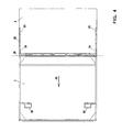
- FIG. 3 Now, the bottom plate 1 of the container from the direction of the arrow IIIA in FIG. 1 with the edge strip 23, the folded inward rear wall 4 and the outside of the back wall 4 folded lid 7 shown.
- FIG. 3A It can be seen that with the same dimensions of the width of the bottom plate 1 and the height of the rear wall 4 including the edge strip 23 when the lid 7, which has a width corresponding to the bottom plate 1, folded on the back wall 4 rests, the cover 7 outside protrudes beyond the bottom plate 1. This is because the rear side wall 4, due to the edge strip 23, is shorter than the corresponding dimension of the lid 7.
- the edge strip 23 of the rear side wall 4 is required to the rear side wall 4 in a plane above the two end side walls 3 and 4 with the connected door leaves 5 and 6 to bring, as the FIG. 2 shows and explained above. Since such over the base of the bottom plate 1 protruding cover 7 is not acceptable due to transport and space requirements, the lid 7, relative to the rear wall 4, held displaceable in the direction of arrow 43, in the region of the pivot axis 26, so that the lid 7 can be moved into such a position in which its free edge 31 terminates with the edge of the bottom plate 1 or directly above the edge strip 23. As a result, even in the folded state of the transport container whose Grund perennial feeling, given by the bottom plate 1, not exceeded.
- FIG. 4 an embodiment in which the lid 7 and its hinge 26 is held on a U-shaped bracket 32.
- the two free legs 33 of the U-shaped bracket 32 are in sleeve parts 34 which is fixedly secured to the rear wall 4, out.
- the cover 7 can be moved in the direction of the arrow 43 until the thickened ends of the legs 33 of the bracket 32 at reach the end faces of the sleeves 34 to the plant.
- the displacement of the cover 7 relative to the rear side wall 4 can also be solved in other ways; However, the displacement mechanism should be kept as flat as possible in order not to increase the overall height of the transport container in the folded state too much.
- FIG. 5 the hinge connection 9 between the right, first side wall 2 and the right, first door 5 is shown.
- This hinge connection is formed by a thin tube or rod 35 and a thick tube 36 pushed over it.
- the thin rod 35 is part of the first end wall 2 and is held between an upper bar 37 and a lower bar 38 at its ends. Between the thin rod 35 and the wall plate of the end wall 2, a small gap 39 is left so as not to hinder the rotation of the thick tube 36.
- the door 5 is fixed, so that the door leaf 5 with the guided around thin rod 35 tube 36 is pivotable, as described above with reference to FIG. 1 is explained.
- FIG. 5 the hinge connection 9 between the right, first side wall 2 and the right, first door 5 is shown.
- This hinge connection is formed by a thin tube or rod 35 and a thick tube 36 pushed over it.
- the thin rod 35 is part of the first end wall 2 and is held between an upper bar 37 and a lower bar 38 at its ends.
- a small gap 39 is left so as not to
- the tube 36 is shorter than the rod 35, by a length corresponding to the height of reinforcing plates 40, which stiffen the lower corner portion of the transport container and are fixedly connected to the bottom plate 1.
- locking parts can be provided, which only then release from a corresponding engagement when the door leaf 5, before a pivoting movement, is lifted upwards in the direction of the arrow 41.
- Such locking parts can be provided directly in the region of the reinforcing plates 40, or between the lower edge of the door leaf 5 and the bottom plate. 1
- the cover 7 has a raised edge, or edge parts, designated by the reference numeral 42 has.
- This edge 42 serves as in FIG. 6 is shown, individual transport containers, in particular in their folded state, stacked to arrange so that they can not move to each other. Because of this edge 42 but also both folded transport containers and transport containers that are unfolded, and also filled with objects, can be stacked. Based on FIG. 6 It can also be seen that about three of the folded transport containers occupy the space of an unfolded transport container.
- Essential for the transport container is the principle of how his individual parts can be folded so that they save space, not exceed the basic size, but also in the unfolded state are very stable and especially suitable for being made of metal.
Abstract
Description
Die vorliegende Erfindung betrifft einen Transport- und Vorratsbehälter zum Transportieren und Bereitstellen von Gegenständen, insbesondere von Kraftfahrzeugzubehörteilen im Bereich von Montagebändern, der eine Bodenplatte, eine erste Stirnseitenwand und eine gegenüberliegende zweite Stirnseitenwand, eine Rückseitenwand, eine der Rückseitenwand gegenüberliegende Vorderseitenwand und einen der Bodenplatte gegenüberliegenden, schwenkbar befestigten Deckel aufweist, wobei der Behälter im leeren Zustand in seinen Außenabmessungen durch zumindest teilweises Verschwenken der Wände zueinander verkleinerbar ist, wozu Bodenplatte und Wände und Wände mit Wänden durch Scharniere verbunden sind.The present invention relates to a transport and storage container for transporting and providing objects, in particular of motor vehicle accessories in the range of mounting bands, a bottom plate, a first end wall and an opposite second end wall, a rear wall, a rear wall opposite the front wall and a bottom plate opposite , pivotally mounted lid, wherein the container in the empty state in its outer dimensions by at least partially pivoting the walls is reduced to each other, including bottom plate and walls and walls are connected to walls by hinges.
Transportbehälter, wie sie vorstehend angegeben sind, werden in vielfältiger Weise dazu verwendet, die unterschiedlichsten Gegenstände zu transportieren. Insbesondere werden solche Transportbehälter im Bereich der Automobilindustrie eingesetzt, um Zubehörteile, Baugruppen oder sonstige Teile, die zur Montage eines Fahrzeugs notwendig sind, von dem Zulieferer zu dem Automobilhersteller zu transportieren. An dem Montageband des Automobilherstellers werden dann solche Transportbehälter aufgestellt, um die darin angelieferten Teile herauszunehmen und am Fahrzeug zu montieren.Transport containers, as indicated above, are used in a variety of ways to transport a wide variety of items. In particular, such transport containers are used in the automotive industry to transport accessories, assemblies or other parts necessary for mounting a vehicle from the supplier to the automobile manufacturer. On the assembly line of the car manufacturer then such transport containers are set up to take out the parts supplied therein and mounted on the vehicle.
Diese Transportbehälter müssen sehr stabil sein, damit die darin transportierten Teile nicht beschädigt werden. Die Transportbehälter müssen auch wiederverwendbar sein, um sie wiederholt für den vorgesehenen Transport einzusetzen. Aus diesem Grund sind solche Behälter üblicherweise aus Metall hergestellt, wodurch sie ein nicht unerhebliches Gewicht aufweisen.These transport containers must be very stable, so that the transported parts are not damaged. The transport containers must also be reusable in order to use them repeatedly for the intended transport. For this reason, such containers are usually made of metal, whereby they have a significant weight.
Eine weitere Anforderung, die an solche Behälter gestellt wird, ist die Einhaltung vorgegebener Grundflächenmaße; übliche Behälter, wie sie in dem vorstehend angegebenen Bereich eingesetzt werden, besitzen eine Länge von 1150 mm, eine Breite von 1000 mm und eine Höhe von 1000 mm. Auch sind Abmessungen von 1200 x 1000 x 1000 oder 1200 x 800 x 1000 (jeweils Länge x Breite x Höhe) üblich. Insbesondere Behälter dieser Größe sind Gegenstand der vorliegenden Erfindung.Another requirement placed on such containers is compliance with given footprint dimensions; conventional containers, as in the above Used have a length of 1150 mm, a width of 1000 mm and a height of 1000 mm. Also, dimensions of 1200 x 1000 x 1000 or 1200 x 800 x 1000 (each length x width x height) are common. In particular, containers of this size are the subject of the present invention.
Da die entleerten Behälter wieder zurück zu dem Lieferanten transportiert werden müssen, ist es, um die Transportkosten gering zu halten, erforderlich, dass die leeren Transport- und Vorratsbehälter in ihren Außenabmessungen verkleinert werden können, d.h. sie müssen zerlegt oder zusammengeklappt werden, dürfen aber gleichzeitig nicht das vorgegebene Grundflächenmaß, auch im zusammengelegten oder zusammengeklappten Zustand, überschreiten.Since the emptied containers must be transported back to the supplier, in order to keep the transport costs low, it is necessary that the empty transport and storage containers can be reduced in their outer dimensions, i. they must be disassembled or folded, but at the same time they must not exceed the given basic surface dimension, even when folded or folded.
Dokument
Eine weitere Anforderung, die an einen solchen Transport- und vorratsbehalter gestellt wird, ist diejenige, dass neben einem Deckel, der der Bodenplatte gegenüberliegt, auch eine Vorderseitenwand geöffnet werden kann, damit am Montageband die in dem Behälter bereitgestellten Teile herausgenommen werden können. Gleichzeitig müssen diese Behälter stapelbar sein, so dass bei der Montage auch mehrere Behälter übereinandergestellt werden können, um dann über die jeweiligen geöffneten Vorderseitenwände die Teile entnehmen zu können.Another requirement placed on such a transport and storage container is that, in addition to a lid opposite the bottom plate, a front wall can also be opened so that the parts provided in the container can be removed on the assembly line. At the same time, these containers must be stackable so that several containers can be placed one above the other during assembly in order then to be able to remove the parts via the respective open front side walls.
Ausgehend von dem vorstehend beschriebenen Stand der Technik und den entsprechenden Vorgaben, die solche Transport- und Vorratsbehälter erfüllen müssen, liegt der vorliegenden Erfindung die Aufgabe zugrunde, einen Transport- und Vorratsbehälter der eingangs angegebenen Art derart weiterzubilden, dass ein sicherer Transport der Gegenstände gewährleistet wird, dass eine einfache Entnahme von Gegenständen ermöglicht wird und dass der Behälter auch im leeren Zustand raumsparend transportiert werden kann, ohne dass dazu eine Vielzahl von Einzelteilen gehandhabt werden muss.Based on the above-described prior art and the corresponding specifications that must meet such transport and storage containers, the present invention seeks to provide a transport and storage container of the type described in such a way that a secure transport of the items is guaranteed in that a simple removal of objects is made possible and that the container can be transported in a space-saving manner even when empty, without having to handle a large number of individual parts.
Diese Aufgabe wird erfindungsgemäß durch einen Transport- und Vorratsbehälter gemäß Anspruch 1 gelöst.This object is achieved by a transport and storage container according to
Weitere bevorzugte Ausgestaltungen des Transport- und Vorratsbehälters sind in den abhängigen Ansprüchen angegeben.Further preferred embodiments of the transport and storage container are specified in the dependent claims.
Es wird somit ein Transport- und Vorratsbehälter geschaffen, der sowohl einen Dekkel als auch vordere Türflügel aufweist, so dass die entsprechend in dem Behälter zu verstauenden Teile sowohl von oben über den Deckel als auch über die vordere Türöffnung in den Behälter eingebracht oder aus diesem herausgenommen werden können. Gleichzeitig ist es aber auch möglich, den Transport- und Vorratsbehälter so zusammenzuklappen, dass er im zusammengeklappten Zustand eine wesentlich geringere Bauhöhe aufweist und dadurch raumsparend im leeren Zustand transportiert und gelagert werden kann. Dabei ist von Vorteil, dass alle Teile, d.h. die Bodenplatte, die Stirnseitenwände, die Rückwand und der Deckel und die Türflügel auch im zusammengeklappten Zustand miteinander, über entsprechende Scharniere, verbunden sind. Es sind keine Einzelteile zu handhaben, weder beim Auseinanderklappen des Transport- und Vorratsbehälters noch beim Zusammenlegen des Behälters. Außerdem ist der Behälter in seiner Konstruktion so ausgelegt, dass er insbesondere aus stabilen Materialien, wie beispielsweise Metall, hergestellt werden kann, aber dennoch durch den erfindungsgemäßen Aufbau ein relativ geringes Gewicht, trotz hoher Stabilität, aufweist.It is thus provided a transport and storage container having both a lid and front door, so that the corresponding parts to be stowed in the container introduced from above the lid and on the front door opening into the container or taken out of this can be. At the same time it is also possible to collapse the transport and storage container so that it has a much lower height in the folded state and thereby can be transported and stored to save space in the empty state. It is advantageous that all parts, i. the bottom plate, the end walls, the rear wall and the lid and the door leaves are also connected in the folded state, via corresponding hinges. There are no items to handle, either when unfolding the transport and storage container still when folding the container. In addition, the container is designed in its construction, that it can be made in particular of stable materials, such as metal, but still has a relatively low weight, despite high stability, by the structure according to the invention.
Damit sich der erste Türflügel flächig auf die Bodenplatte beim Zusammenklappen des Behälters auflegt, sollte die Schwenkachse zwischen der Bodenplatte und der ersten Stirnseitenwand in einem entsprechenden Abstand oberhalb der Ebene der Bodenplatte liegen. Durch eine solche flächige Auflage der einzelnen Platten des Behälters, d.h. nicht nur der Bodenplatte und der ersten Stirnseitenwand, sondern auch der anderen Wände, wird eine geringstmögliche Bauhöhe in zusammengeklapptem Zustand erreicht.In order for the first door leaf to lie flat on the base plate when folding the container, the pivot axis should lie between the bottom plate and the first end wall at a corresponding distance above the plane of the bottom plate. By such a flat support of the individual plates of the container, i. not only the bottom plate and the first end wall, but also the other walls, a lowest possible height is achieved in the folded state.
Weiterhin sollte die Schwenkachse zwischen der Bodenplatte und der zweiten Stirnseitenwand in einem Abstand oberhalb der Ebene der Bodenplatte liegen, der etwa der Summe der Dicke der ersten Stirnseitenwand und des ersten Türflügels entspricht. So können unter dieser zweiten Stirnseitenwand und dem zweiten Türflügel die erste Stirnseitenwand und der erste Türflügel aufgenommen werden.Furthermore, the pivot axis should lie between the bottom plate and the second end wall at a distance above the plane of the bottom plate, which corresponds approximately to the sum of the thickness of the first end wall and the first door leaf. Thus, the first end wall and the first door can be added under this second end wall and the second door.
Auch sollte die Schwenkachse zwischen der Bodenplatte und der Rückseitenwand in einem Abstand oberhalb der Ebene der Bodenplatte liegen, der etwa der Summe der Dicke der ersten Stirnseitenwand und des ersten Türflügels und der Dicke der zweiten Stirnseitenwand und des zweiten Türflügels entspricht, so dass sich Rückenseitenwand und Deckel flächig auf die darunterliegende zweite Stirnseitenwand auflegen können.Also, the pivot axis between the bottom plate and the rear wall should be at a distance above the plane of the bottom plate, which is about the sum of Thickness of the first end wall and the first door leaf and the thickness of the second end wall and the second door leaf corresponds, so that the back side wall and lid can lay flat on the underlying second end wall.
Um die entsprechende Lage der Schwenkachse der ersten Stirnseitenwand zu erreichen, wird die Schwenkachse an der oberen Kante eines feststehenden, mit der Bodenplatte verbundenen Abschnitts der ersten Stirnseitenwand gebildet.In order to achieve the corresponding position of the pivot axis of the first end wall, the pivot axis is formed at the upper edge of a fixed, connected to the bottom plate portion of the first end wall.
Gleiches gilt für die Schwenkachse der zweiten Stirnseitenwand, die vorzugsweise an der oberen Kante eines feststehenden, mit der Bodenplatte verbundenen Abschnitts der zweiten Stirnseitenwand gebildet ist.The same applies to the pivot axis of the second end wall, which is preferably formed at the upper edge of a fixed, connected to the bottom plate portion of the second end wall.
Auch sollte vorzugsweise die Schwenkachse der Rückseitenwand an der oberen Kante eines feststehenden, mit der Bodenplatte verbundenen Abschnitts der Rückseitenwand durch entsprechende Teile gebildet sein .Also, preferably, the pivot axis of the rear side wall should be formed at the upper edge of a fixed, connected to the bottom plate portion of the rear side wall by corresponding parts.
Um den Behälter während des Transports in seinem aufgeklappten Zustand fest verschließen zu können, sind die jeweiligen Türflügel jeweils mit der Bodenplatte einerseits und mit dem Deckel andererseits durch mindestens eine Verriegelung verriegelbar. In einer einfachen Form wird diese Verriegelung durch zwei Riegel, oben und unten an der Tür, gebildet, die in die Bodenplatte bzw. den Deckel eingreifen.In order to close the container during transport in its unfolded state, the respective door wings are each locked to the bottom plate on the one hand and the lid on the other hand by at least one lock. In a simple form, this lock is formed by two bolts, top and bottom of the door, which engage in the bottom plate and the lid, respectively.
Auch kann eine den Behälter versteifende Verriegelung vorgesehen werden, die die Bodenplatte gegen den Deckel verspannt. Eine solche Verriegelung kann durch einen schwenkbar an dem Türflügel gehaltenen Schwenkarm gebildet werden .Also, a container stiffening latch can be provided, which braces the bottom plate against the lid. Such a lock can be formed by a pivotally mounted on the door swing arm.
Ein solcher Schwenkarm greift dann bevorzugt mit seinen Enden in jeweils eine Verriegelungsnase an der Bodenplatte und an dem Deckel ein.Such a pivot arm then preferably engages with its ends in each case a locking lug on the bottom plate and on the lid.
Um diesen Schwenkarm konstruktiv einfach zu gestalten, sollte der Schwenkpunkt des Schwenkarms etwa in der halben Höhe des Türflügels angeordnet sein.To make this swivel arm structurally simple, the pivot point of the swivel arm should be located approximately at half the height of the door leaf.
Wie bereits eingangs erwähnt, ist es ein unumgängliches Erfordernis, dass ein solcher Transport- und Vorratsbehälter auch im zusammengeklappten Zustand das Grundflächenmaß, das durch die Bodenplatte vorgegeben ist, in Projektion auf die Bodenplatte nicht übersteigt. Dies ist dann nicht gegeben, wenn die Höhe der Rückseitenwand, die umgeklappt wird, geringer ist als die Breite des Deckels. In einem solchen Fall steht dann der auf die Außenseite der Rückseitenwand geschwenkte Deckel mit seinem Rand über die Rückseitenwand, und zwar an der Seite der Rückseitenwand, an der sich das Scharnier befindet, vor. Hierdurch wird das Grundflächenmaß durch den vorstehenden Teil des Deckels überschritten. Um diesen Zustand zu vermeiden, wird die Schwenkachse zwischen Rückseitenwand und Deckel durch mindestens ein entsprechendes Scharnier gebildet, das dem Deckel zugeordnet ist, und dieses Scharnier mit dem Deckel wird in einer Führungsanordnung an der Rückseitenwand so gehalten, dass das Scharnier von der zugeordneten Längskante der Rückseitenwand beabstandbar ist. Das bedeutet, dass mit einer solchen Anordnung der auf die Außenseite der Rückenwand geklappte Deckel so verschoben werden kann, dass der Rand des über das Grundflächenmaß vorstehende Bereichs des Deckels mit der Kante der Bodenplatte abschließt.As already mentioned, it is an unavoidable requirement that such a transport and storage container in the folded state, the Grundflächenmaß, which is predetermined by the bottom plate, in projection on the Bottom plate does not exceed. This is not the case if the height of the rear wall, which is folded over, is less than the width of the lid. In such a case, then the lid pivoted on the outside of the back wall with its edge over the back wall, on the side of the rear side wall, where the hinge is located before. As a result, the Grundflächenmaß is exceeded by the projecting part of the lid. To avoid this condition, the pivot axis between the rear wall and lid is formed by at least one corresponding hinge associated with the lid, and this hinge with the lid is held in a guide arrangement on the rear wall so that the hinge separates from the associated longitudinal edge of the lid Rear side wall is spaced. This means that with such an arrangement, the lid folded onto the outside of the back wall can be displaced such that the edge of the region of the lid projecting beyond the basic surface dimension closes with the edge of the bottom plate.
Eine solche Führungsanordnung kann durch zwei Stäbe, die jeweils in einer der Rückseitenwand zugeordneten Hülse geführt sind, gebildet sein.Such a guide arrangement can be formed by two rods which are each guided in a sleeve assigned to the rear wall.
Die zwei Stäbe können dabei durch die freien Enden eines U-förmigen Bügels gebildet sein, wobei das die beiden Enden verbindende Querteil des U-förmigen Bügels dem Deckel zugeordnet ist.The two rods can be formed by the free ends of a U-shaped bracket, wherein the transverse ends connecting the two ends of the U-shaped bracket is associated with the lid.
Es besteht dabei auch die Möglichkeit, den Deckel in zwei Teile zu unterteilen, die mit einem Scharnier verbunden sind, so dass der über das Grundmaß vorstehende Teil des Deckels im zusammengeklappten Zustand nach innen auf den anderen Deckelteil geklappt werden kann. Dadurch erhöht sich allerdings die Höhe des zusammengeklappten Transport- und Vorratsbehälters um die Dicke des umgeklappten Deckelteils.It is also possible to divide the lid into two parts, which are connected to a hinge, so that the projecting over the basic dimension of the lid can be folded in the folded state inwards on the other cover part. As a result, however, the height of the folded transport and storage container increases by the thickness of the folded lid part.
Um eine stabile Verbindung zwischen den Türflügeln und den zugeordneten Stirnseitenwänden zu schaffen, wird die jeweilige schwenkbare Verbindung zwischen der ersten Stirnseitenwand und dem ersten Türflügel und zwischen der zweiten Stirnseitenwand und dem zweiten Türflügel durch eine rohrförmige Anordnung gebildet, mit einem dickeren Rohrabschnitt, der dem Türflügel zugeordnet ist, und einem dünneren Rohrabschnitt, der der Stirnseitenwand zugeordnet ist. Der dünne Rohrabschnitt, der der Stirnseitenwand zugeordnet ist, ist nur an seinem oberen und unteren Ende gehalten, so dass sich der dicke Rohrabschnitt mit dem daran befestigten Türflügel frei um den dünnen Rohrabschnitt drehen kann.In order to provide a stable connection between the door wings and the associated end walls, the respective pivotal connection between the first end wall and the first door and between the second end wall and the second door is formed by a tubular arrangement, with a thicker pipe section, the door leaf is assigned, and a thinner Pipe section, which is assigned to the end wall. The thin pipe section, which is associated with the end wall, is held only at its upper and lower ends, so that the thick pipe section with the attached door can rotate freely around the thin pipe section.
Um die Stabilität des Behälters noch zu erhöhen, können in den Eckenbereichen der Bodenplatte und der Seitenwände, der Rückwand und der Türflügel Verstärkungsplatten angeordnet werden.In order to increase the stability of the container even more, reinforcing plates can be arranged in the corner regions of the bottom plate and the side walls, the rear wall and the door leaf.
Weiterhin ist es bevorzugt, die Länge des dickeren Rohrabschnitts so zu wählen, dass sie geringer ist als die Höhe der Seitenkante des Türflügels bzw. der Stirnseitenwand; dadurch kann der Türflügel angehoben und wieder abgesenkt werden, um ihn beispielsweise aus entsprechenden Verriegelungsteilen zu lösen oder wieder mit solchen Verriegelungsteilen in Eingriff zu bringen. Falls der Behälter die vorstehend angeführten Verstärkungsplatten aufweist, sollte der dicke Rohrabschnitt eine Länge haben, die der Länge der Seitenkante der Stirnseitenwand entspricht minus der Höhe dieser Verstärkungsplatten, so dass der dicke Rohrabschnitt des Türflügels oberhalb der Verstärkungsplatte angehoben werden kann. Dadurch kann zum Beispiel der Türflügel aus einer Verriegelung mit der Verstärkungsplatte gelöst werden.Furthermore, it is preferable to choose the length of the thicker pipe section so that it is less than the height of the side edge of the door leaf or the end wall; thereby the door can be raised and lowered again, for example, to release it from corresponding locking parts or to bring back with such locking parts in engagement. If the container has the above-mentioned reinforcing plates, the thick tube section should have a length which corresponds to the length of the side edge of the end wall minus the height of these reinforcing plates, so that the thick tube section of the door leaf can be raised above the reinforcing plate. As a result, for example, the door can be released from a lock with the reinforcing plate.
Um Behälter sicher übereinander stapeln zu können, sie aber auch mit Gabelstaplern erfassen zu können, sind auf der Unterseite der Bodenplatte Fußteile ausgebildet, die sich auf der Innenseite eines auf der Außenseite des Deckels ausgebildeten Rands, bei übereinander gestapelten Behältern, anlegen; hierbei reicht eine Randhöhe von ein paar Millimetern aus.In order to be able to stack containers safely one above the other, but also to be able to detect them with forklifts, foot parts are formed on the underside of the bottom plate, which rest on the inside of a rim formed on the outside of the lid, with containers stacked one above the other; Here, an edge height of a few millimeters is sufficient.
Weitere Einzelheiten und Merkmale der Erfindung ergeben sich aus der nachfolgenden Beschreibung eines Ausführungsbeispiels anhand der Zeichnungen. In der Zeichnung zeigt
Figur 1- eine schematische Zeichnung eines Behälters gemäß der Erfindung im aufgeklappten Zustand, in der die verschiedenen, schwenkbaren Zuordnungen der einzelnen Teile durch Schwenkachsen und Schwenkpfeile angedeutet sind,
Figur 2- eine schematische Ansicht auf den Behälter der
Figur 1Sichtpfeils 2 inFigur 1 - Figur 3A
- eine schematische Ansicht auf den Behälter der
Figur 1 - Figur 3B
- eine der
Figur 3A entsprechende Darstellung, allerdings mit verschobenem Deckel, Figur 4- eine Draufsicht auf die Rückseitenwand und dem damit verbundenen Deckel, wobei der Deckel nur zum Teil zu sehen ist,
Figur 5- die rechte Seite des Behälters der
Figur 1 in einer leicht vergrößerten Darstellung, um die Verbindung zwischen der Stirnseitenwand und dem einen Türflügel zu zeigen, und Figur 6- drei zusammengeklappte Behälter, wie sie auch in
Figur 2
- FIG. 1
- a schematic drawing of a container according to the invention in the unfolded state, in which the different, pivotable assignments of the individual parts are indicated by pivot axes and pivot arrows,
- FIG. 2
- a schematic view of the container of
FIG. 1 from the direction of thesighting arrow 2 inFIG. 1 when the container is folded to show the arrangement of the individual parts of the container, - FIG. 3A
- a schematic view of the container of
FIG. 1 from the direction of the arrow IIIA, however, only the bottom plate is shown with the rear side wall and the lid, and the lid protrudes in projection onto the bottom plate over the edge, - FIG. 3B
- one of the
FIG. 3A corresponding representation, but with shifted cover, - FIG. 4
- a top view of the rear wall and the associated lid, the lid is only partially visible,
- FIG. 5
- the right side of the container
FIG. 1 in a slightly enlarged view to show the connection between the front wall and the one door, and - FIG. 6
- three collapsed containers, as well as in
FIG. 2 can be seen in a stacked arrangement.
Der Transportbehälter, wie er in den Figuren, insbesondere in der
Um den Transport- und Vorratsbehälter, wie er in
Es ist darauf hinzuweisen, dass, soweit in den Figuren von Scharnieren gesprochen wird, in den Figuren lediglich die entsprechenden Schwenkachsen gezeigt sindIt should be noted that, as far as in the figures of hinges is spoken, in the figures, only the corresponding pivot axes are shown
Weiterhin ist der in
Die erste Stirnseitenwand 2 ist um ein Scharnier 15 in Richtung des Schwenkpfeils 16 bzw. des Schwenkpfeils 17 zur Bodenplatte 1 hin schwenkbar. Entsprechendes gilt auch für die zweite Stirnseitenwand 3, die um eine Schwenkachse 18 in Richtung des Schwenkpfeils 19 bzw. 20 schwenkbar ist. Wie anhand der
Schließlich ist die Rückseitenwand 4 an der Bodenplatte 1 bzw. an einem Randstreifen 23, der fest mit der Bodenplatte 1 verbunden ist und einen Teil der Rückseitenwand 4 bildet, über ein Scharnier 24, das um die Schwenkachse 25 schwenkbar ist, gehalten. Der Deckel 7 ist an dem oberen Rand der Rückseitenwand 4 mittels eines Scharniers 26 verbunden, das in Richtung des Schwenkpfeils 27 um 270° nach außen derart geschwenkt werden kann, dass sich der Deckel 7 mit seiner Außenseite auf die Außenseite der Rückseitenwand 4 auflegt.Finally, the
Um den Transportbehälter der
In
Nachdem die Verriegelungen gelöst sind, wird zunächst der rechte, erste Türflügel 5 auf die Innenseite der ersten Stirnseitenwand 2 geschwenkt. Danach wird die Stirnseitenwand 2 um das Scharnier 15 herum, mit dem darunterliegenden ersten Türflügel 5, zur Bodenplatte 1 hin geschwenkt und auf die Bodenplatte 1 aufgelegt. Diese Anordnung von Bodenplatte 1, erstem Türflügel 5 und erster Stirnseitenwand 2 ist in
In
Um eine solche Verschiebung des Deckels 7 zu ermöglichen, zeigt
Die Verschiebung des Deckels 7 relativ zu der Rückseitenwand 4 kann auch in anderer Weise gelöst werden; allerdings sollte der Verschiebemechanismus möglichst flach gehalten werden, um die Bauhöhe des Transportbehälters in zusammengeklapptem Zustand nicht zu stark zu erhöhen.The displacement of the
In
Anhand der
Wesentlich für den Transportbehälter, der hier in Rede stehenden Art, wie er vorstehend beschrieben ist, ist das Prinzip, wie sich seine einzelnen Teile so zusammenklappen lassen, dass sie platzsparend, das Grundmaß nicht überschreiten, aber auch im aufgeklappten Zustand sehr stabil sind und sich insbesondere auch dazu eignen, aus Metall hergestellt zu werden.Essential for the transport container, the type in question, as described above, is the principle of how his individual parts can be folded so that they save space, not exceed the basic size, but also in the unfolded state are very stable and especially suitable for being made of metal.
Claims (29)
- A transport and storage container for transporting and providing articles, particularly vehicle accessories in the area of assembly lines, which comprises a base plate, a first face wall and a second opposing face wall, a rear side wall, a front side wall opposite to the rear side wall, and a pivotably fastened lid opposite to the base plate, the container in its empty state being reducible in size in its outer dimensions by at least partly pivoting the walls relative to one another, to which end base plate and walls and walls with walls are connected by means of hinges,
characterized in
that the front side wall is subdivided to form a first and second door leaf (5, 6),
that the first door leaf (5) is retained with the vertically extending side edge of the first face wall (2) to be pivotable in such a manner that the first door leaf (5) comes to rest on the inside of the first face wall (2),
that the first face wall (2) is retained on the associated face of the base plate (1) to be pivotable in such a manner that said first face wall (2) is pivotable with the inwardly resting first door leaf (5) relative to the base plate (1) such that the first door leaf (5) comes to rest on the base plate (1),
that the second door leaf (6) is retained with the vertically extending side edge of the second face wall (3) to be pivotable in such a manner that said second door leaf (6) comes to rest on the inside of the second face wall (3),
that the second face wall (3) is retained on the associated face of the base plate (1), with the pivot axis (18) lying in a corresponding way above the plane of the base plate (1), to be pivotable such that said second face wall (3) is pivotable with the internally resting second door leaf (6) relative to the base plate (1) such that the second door leaf (6) comes to rest on the outside of the first face wall (2),
that the lid (7) is retained to be pivotable on the upper longitudinal edge of the rear side wall (4) so that the lid (7) with its outside can be made to rest on the outside of the rear side wall (4),
that the rear side wall (4) is retained on the associated longitudinal side of the base plate (1), with the pivot axis (24) lying in a corresponding manner above the plane of the base plate (1), to be pivotable such that said rear side wall (4) is pivotable with the externally resting lid (7) relative to the base plate (1) so that the inside of the rear side wall (4) comes to rest on the outside of the second face wall (3). - The transport and storage container according to claim 1, characterized in that the pivot axis (15) between the base plate (1) and the first face wall (2) is positioned at a distance above the plane of the base plate (1) such that the first door leaf (5) comes to lie flat on the base plate (1).
- The transport and storage container according to claim 1 or 2, characterized in that the pivot axis (18) between the base plate (1) and the second face wall (3) is positioned at a distance above the plane of the base plate (1), said distance approximately corresponding to the sum of the thickness of the first face wall (2) and of the first door leaf (5).
- The transport and storage container according to any one of claims 1 to 3, characterized in that the pivot axis (24) between the base plate (1) and the rear side wall (4) is positioned at a distance above the plane of the base plate (1), said distance approximately corresponding to the sum of the thickness of the first face wall (2) and the first door leaf (5) and the thickness of the second face wall (3) and the second door leaf (6).
- The transport and storage container according to any one of claims 2 to 4, characterized in that the pivot axis (15) of the first face wall (2) is formed on the upper edge of a stationary section (21) of the first face wall (3), said section (21) being connected to the base plate (1).
- The transport and storage container according to any one of claims 3 to 5, characterized in that the pivot axis (18) of the second face wall (3) is formed on the upper edge of a stationary section (22) of the second face wall (3), said section (22) being connected to the base plate (1).
- The transport and storage container according to any one of claims 3 to 6, characterized in that the pivot axis (24) of the rear side wall (4) is formed on the upper edge of a stationary section (23) of the rear side wall (4), said section (23) being connected to the base plate (1).
- The transport and storage container according to any one of claims 1 to 7, characterized in that each door leaf (5, 6) in the erected state of the container is lockable to the base plate (1) on the one hand and to the lid (7) on the other hand by means of at least one lock.
- The transport and storage container according to claim 8, characterized in that through the lock the base plate (1) is clamped against the lid (7).
- The transport and storage container according to claim 8 or 9, characterized in that the lock is formed by a pivot arm (28) which is pivotably retained on the door leaf (5; 6).
- The transport and storage container according to claim 10, characterized in that the pivot arm engages with its ends into a locking nose on the base plate (1) and on the lid (7), respectively.
- The transport and storage container according to claim 10 or 11, characterized in that the pivot point of the pivot arm is arranged approximately at half the height of the door leaf (5; 6).
- The transport and storage container according to any one of claims 1 to 12, characterized in that the pivot axis (26) between rear side wall (4) and lid (7) is formed by at least one associated hinge assigned to the lid (7), and said hinge (26) is retained with the lid (7) in a guide assembly (32, 33, 34) on the rear side wall (4) such that the hinge (26) can be spaced apart from the associated longitudinal edge of the rear side wall (4).
- The transport and storage container according to claim 13, characterized in that the distance of the hinge (26) from the associated edge of the rear side wall (4) can be chosen such that the lid (7), in a projection above the bottom plate (1), can be positioned congruently.
- The transport and storage container according to claim 13 or claim 14, characterized in that the guide assembly (32, 33, 34) is formed by two bars (33), each being guided in a sleeve (34) assigned to the rear side wall (4).
- The transport and storage container according to claim 15, characterized in that the two bars (33) are formed by the free ends of a U-shaped bracket (32), the transverse member of the U-shaped bracket (32), which connects the two ends (33), being assigned to the lid (7).
- The transport and storage container according to any one of claims 1 to 16, characterized in that the respective pivotable connection (9; 12) between the first face wall (2) and the first door leaf (5) and between the second face wall (3) and the second door leaf (6) is formed by a tubular assembly (35, 36), with a thicker tube section (36) being assigned to the door leaf (5; 6), and a thinner tube section (35) assigned to the face wall (2; 3).
- The transport and storage container according to any one of claims 1 to 17, characterized in that reinforcement plates (40) are arranged in the corner portions of the base plate (1) and the face walls (2; 3), the rear side wall (4) and/or the door leaf (5, 6).
- The transport and storage container according to claim 17 and claim 18, characterized in that the thicker tube section (36) has a length corresponding to the height of the side edge of the door leaf (5; 6) and the face wall (2; 3), respectively, minus the height of the reinforcement plate (40).
- The transport and storage container according to claim 19, characterized in that the door leaf (5; 6) in the tubular assembly (35, 36) is liftable for pivoting the door leaf (5; 6) to the inside of the face wall (2; 3) so that the lower edge of the door leaf (5; 6) moves above the reinforcement plate (40).
- The transport and storage container according to claim 20, characterized in that with the lifting of the door leaf (5; 6) the door leaf (5; 6) is disengaged from a lock.
- The transport and storage container according to claim 21, characterized in that the door leaf (5; 6) is disengaged from a lock with the reinforcement plate (40).
- The transport and storage container according to claim 21, characterized in that the door leaf (5; 6) is disengaged from a lock with the base plate (1).
- The transport and storage container according to claim 23, characterized in that the lock is formed by a pin which engages into a corresponding bore.
- The transport and storage container according to any one of claims 1 to 24, characterized in that the lid (7) is subdivided into two lid parts in longitudinal direction, the two lid parts being retained with a hinge to be pivotable relative to each other such that the one lid part is pivotable towards the other lid part.
- The transport and storage container according to any one of claims 1 to 25, characterized in that base members (8) which in the stacked condition of containers come to rest on the inside of an edge (42) formed on the outside of the lid (7) are formed on the bottom side of the base plate (1).
- The transport and storage container according to any one of claims 1 to 26, characterized in that at least the base plate (1), the face walls (2, 3), the rear side wall (4) and the lid (7) are formed from metal plates.
- The transport and storage container according to any one of claims 1 to 7, characterized in that the lid (7) in the erected state of the container comprises locks (28) which are lockable (30) on the face walls (2, 3).
- The transport and storage container according to claim 28, characterized in that the door leaves (5, 6) are locked with the lid (7).
Applications Claiming Priority (2)
| Application Number | Priority Date | Filing Date | Title |
|---|---|---|---|
| DE102004060400A DE102004060400A1 (en) | 2004-12-14 | 2004-12-14 | Transport and storage container |
| PCT/EP2005/013325 WO2006063775A1 (en) | 2004-12-14 | 2005-12-13 | Collapsible transport and storage container |
Publications (2)
| Publication Number | Publication Date |
|---|---|
| EP1824747A1 EP1824747A1 (en) | 2007-08-29 |
| EP1824747B1 true EP1824747B1 (en) | 2008-10-01 |
Family
ID=35840662
Family Applications (1)
| Application Number | Title | Priority Date | Filing Date |
|---|---|---|---|
| EP05824662A Not-in-force EP1824747B1 (en) | 2004-12-14 | 2005-12-13 | Collapsible transport and storage container |
Country Status (5)
| Country | Link |
|---|---|
| US (1) | US20080190810A1 (en) |
| EP (1) | EP1824747B1 (en) |
| AT (1) | ATE409653T1 (en) |
| DE (2) | DE102004060400A1 (en) |
| WO (1) | WO2006063775A1 (en) |
Families Citing this family (8)
| Publication number | Priority date | Publication date | Assignee | Title |
|---|---|---|---|---|
| DE102007021813A1 (en) | 2007-05-07 | 2008-11-13 | Manfred Steigerwald | Transport and storage container |
| DE202007015661U1 (en) | 2007-11-08 | 2009-03-19 | Steigerwald, Manfred | Transport and storage container |
| KR100987869B1 (en) * | 2010-03-11 | 2010-10-13 | 현기훈 | Container type foldable pallet |
| USD789648S1 (en) * | 2015-12-04 | 2017-06-13 | Lane J. Segerstrom | Maintainable pallet |
| US10118732B2 (en) | 2016-12-09 | 2018-11-06 | Lane Segerstrom | Maintainable pallet |
| KR102079642B1 (en) * | 2018-02-26 | 2020-02-20 | 김경조 | Stacking rack |
| DK180580B1 (en) * | 2020-01-06 | 2021-09-06 | Maersk As | A collapsible rack for supporting carcasses inside refrigerated inter- modal containers and a method for collapsing such rack |
| ES2939263T3 (en) * | 2020-09-23 | 2023-04-20 | Schneider Transp Und Lagerbehaelter Gmbh & Co Kg | Carrier |
Family Cites Families (8)
| Publication number | Priority date | Publication date | Assignee | Title |
|---|---|---|---|---|
| US13321A (en) * | 1855-07-24 | Hinge | ||
| FR2186393B1 (en) * | 1972-05-31 | 1976-10-29 | Reunis Sa Ateliers | |
| IT1084787B (en) * | 1977-09-30 | 1985-05-28 | Euteco Spa | PERFECTED FOLDABLE CONTAINER |
| US4240555A (en) * | 1978-12-22 | 1980-12-23 | Eagle-Picher Industries, Inc. | Collapsible material handling container |
| US5056667A (en) * | 1988-05-17 | 1991-10-15 | Rees Operations Pty. Ltd. | Collapsible pallet cage |
| CA2352281A1 (en) * | 1998-11-25 | 2000-06-02 | Bent Kofod | Collapsible container for transporting a liquid |
| US6811048B2 (en) * | 2002-02-12 | 2004-11-02 | David M. K. Lau | Fold-up storage container |
| JP3979638B2 (en) * | 2002-07-05 | 2007-09-19 | 株式会社リコー | Goods transportation storage device |
-
2004
- 2004-12-14 DE DE102004060400A patent/DE102004060400A1/en not_active Withdrawn
-
2005
- 2005-12-13 AT AT05824662T patent/ATE409653T1/en not_active IP Right Cessation
- 2005-12-13 WO PCT/EP2005/013325 patent/WO2006063775A1/en active IP Right Grant
- 2005-12-13 DE DE502005005569T patent/DE502005005569D1/en active Active
- 2005-12-13 US US11/792,870 patent/US20080190810A1/en not_active Abandoned
- 2005-12-13 EP EP05824662A patent/EP1824747B1/en not_active Not-in-force
Also Published As
| Publication number | Publication date |
|---|---|
| DE102004060400A1 (en) | 2006-07-06 |
| WO2006063775A1 (en) | 2006-06-22 |
| US20080190810A1 (en) | 2008-08-14 |
| DE502005005569D1 (en) | 2008-11-13 |
| ATE409653T1 (en) | 2008-10-15 |
| EP1824747A1 (en) | 2007-08-29 |
Similar Documents
| Publication | Publication Date | Title |
|---|---|---|
| EP1824747B1 (en) | Collapsible transport and storage container | |
| DE2546645C2 (en) | Collapsible container | |
| EP2575436B1 (en) | Transport box for animals or objects, in particular for fitting in vehicles | |
| EP2840045B1 (en) | Transport container for piece goods | |
| DE2924105A1 (en) | ROLL CONTAINER | |
| DE3010366A1 (en) | ROLLER CONTAINERS WITH SWIVELING SIDEWALLS AND WITH THE SWIVELING ROLLERS CARRYED IN THE AREA OF THE SWIVELING ENDS | |
| DE2740818A1 (en) | STACKABLE LOAD OR ROLLER PALLET | |
| EP3599142B1 (en) | Roller container | |
| DE202006004351U1 (en) | Pallet frame for euro-pallet has carrying piece connected to frame, holding struts with smooth underside at right angles to it which clamp to the space between two cover slats of pallet | |
| DE3633348A1 (en) | Collapsible transport container for unit loads | |
| DE202020100095U1 (en) | Trolleys for transporting, in particular, laundry and / or laundry bags | |
| DE202020105201U1 (en) | Roll container | |
| EP2428434B1 (en) | Locking mechanism for a vehicle superstructure | |
| EP3363748B1 (en) | Stackable and nestable container | |
| DE4135677A1 (en) | Collapsible load support with pallet base - has swivel hinged parts making up side walls for easier assembly and dismantling | |
| DE2557751C3 (en) | Articulated connection, especially on a transport pallet | |
| EP2025611B1 (en) | Articulation unit for the posts of a collapsible transport or storage structure | |
| DE3220859C2 (en) | Long goods container | |
| DE2547436A1 (en) | Collapsible transport container for chemical goods - has sheet metal bottom and angled corner supports reinforced by separate open channels | |
| DE10349656B4 (en) | Pallet for transporting stacked objects | |
| AT521000B1 (en) | Collapsible transport device | |
| DE202015103235U1 (en) | Collapsible container | |
| DE3100787C2 (en) | Transport trolley | |
| DE4405289C1 (en) | Work platform for scaffolding, partic. for concrete sheathing | |
| EP4015346A1 (en) | Roller container |
Legal Events
| Date | Code | Title | Description |
|---|---|---|---|
| PUAI | Public reference made under article 153(3) epc to a published international application that has entered the european phase |
Free format text: ORIGINAL CODE: 0009012 |
|
| 17P | Request for examination filed |
Effective date: 20070523 |
|
| AK | Designated contracting states |
Kind code of ref document: A1 Designated state(s): AT BE BG CH CY CZ DE DK EE ES FI FR GB GR HU IE IS IT LI LT LU LV MC NL PL PT RO SE SI SK TR |
|
| DAX | Request for extension of the european patent (deleted) | ||
| GRAP | Despatch of communication of intention to grant a patent |
Free format text: ORIGINAL CODE: EPIDOSNIGR1 |
|
| GRAS | Grant fee paid |
Free format text: ORIGINAL CODE: EPIDOSNIGR3 |
|
| GRAA | (expected) grant |
Free format text: ORIGINAL CODE: 0009210 |
|
| AK | Designated contracting states |
Kind code of ref document: B1 Designated state(s): AT BE BG CH CY CZ DE DK EE ES FI FR GB GR HU IE IS IT LI LT LU LV MC NL PL PT RO SE SI SK TR |
|
| REG | Reference to a national code |
Ref country code: GB Ref legal event code: FG4D Free format text: NOT ENGLISH |
|
| REG | Reference to a national code |
Ref country code: CH Ref legal event code: EP |
|
| REG | Reference to a national code |
Ref country code: IE Ref legal event code: FG4D Free format text: LANGUAGE OF EP DOCUMENT: GERMAN |
|
| REF | Corresponds to: |
Ref document number: 502005005569 Country of ref document: DE Date of ref document: 20081113 Kind code of ref document: P |
|
| PG25 | Lapsed in a contracting state [announced via postgrant information from national office to epo] |
Ref country code: SI Free format text: LAPSE BECAUSE OF FAILURE TO SUBMIT A TRANSLATION OF THE DESCRIPTION OR TO PAY THE FEE WITHIN THE PRESCRIBED TIME-LIMIT Effective date: 20081001 |
|
| NLV1 | Nl: lapsed or annulled due to failure to fulfill the requirements of art. 29p and 29m of the patents act | ||
| REG | Reference to a national code |
Ref country code: IE Ref legal event code: FD4D |
|
| PG25 | Lapsed in a contracting state [announced via postgrant information from national office to epo] |
Ref country code: BG Free format text: LAPSE BECAUSE OF FAILURE TO SUBMIT A TRANSLATION OF THE DESCRIPTION OR TO PAY THE FEE WITHIN THE PRESCRIBED TIME-LIMIT Effective date: 20090101 Ref country code: ES Free format text: LAPSE BECAUSE OF FAILURE TO SUBMIT A TRANSLATION OF THE DESCRIPTION OR TO PAY THE FEE WITHIN THE PRESCRIBED TIME-LIMIT Effective date: 20090112 Ref country code: LT Free format text: LAPSE BECAUSE OF FAILURE TO SUBMIT A TRANSLATION OF THE DESCRIPTION OR TO PAY THE FEE WITHIN THE PRESCRIBED TIME-LIMIT Effective date: 20081001 |
|
| PG25 | Lapsed in a contracting state [announced via postgrant information from national office to epo] |
Ref country code: NL Free format text: LAPSE BECAUSE OF FAILURE TO SUBMIT A TRANSLATION OF THE DESCRIPTION OR TO PAY THE FEE WITHIN THE PRESCRIBED TIME-LIMIT Effective date: 20081001 Ref country code: FI Free format text: LAPSE BECAUSE OF FAILURE TO SUBMIT A TRANSLATION OF THE DESCRIPTION OR TO PAY THE FEE WITHIN THE PRESCRIBED TIME-LIMIT Effective date: 20081001 Ref country code: PL Free format text: LAPSE BECAUSE OF FAILURE TO SUBMIT A TRANSLATION OF THE DESCRIPTION OR TO PAY THE FEE WITHIN THE PRESCRIBED TIME-LIMIT Effective date: 20081001 Ref country code: PT Free format text: LAPSE BECAUSE OF FAILURE TO SUBMIT A TRANSLATION OF THE DESCRIPTION OR TO PAY THE FEE WITHIN THE PRESCRIBED TIME-LIMIT Effective date: 20090302 Ref country code: IS Free format text: LAPSE BECAUSE OF FAILURE TO SUBMIT A TRANSLATION OF THE DESCRIPTION OR TO PAY THE FEE WITHIN THE PRESCRIBED TIME-LIMIT Effective date: 20090201 Ref country code: LV Free format text: LAPSE BECAUSE OF FAILURE TO SUBMIT A TRANSLATION OF THE DESCRIPTION OR TO PAY THE FEE WITHIN THE PRESCRIBED TIME-LIMIT Effective date: 20081001 |
|
| BERE | Be: lapsed |
Owner name: STEIGERWALD, MANFRED Effective date: 20081231 |
|
| PG25 | Lapsed in a contracting state [announced via postgrant information from national office to epo] |
Ref country code: RO Free format text: LAPSE BECAUSE OF FAILURE TO SUBMIT A TRANSLATION OF THE DESCRIPTION OR TO PAY THE FEE WITHIN THE PRESCRIBED TIME-LIMIT Effective date: 20081001 Ref country code: MC Free format text: LAPSE BECAUSE OF NON-PAYMENT OF DUE FEES Effective date: 20081231 Ref country code: IE Free format text: LAPSE BECAUSE OF FAILURE TO SUBMIT A TRANSLATION OF THE DESCRIPTION OR TO PAY THE FEE WITHIN THE PRESCRIBED TIME-LIMIT Effective date: 20081001 Ref country code: EE Free format text: LAPSE BECAUSE OF FAILURE TO SUBMIT A TRANSLATION OF THE DESCRIPTION OR TO PAY THE FEE WITHIN THE PRESCRIBED TIME-LIMIT Effective date: 20081001 Ref country code: DK Free format text: LAPSE BECAUSE OF FAILURE TO SUBMIT A TRANSLATION OF THE DESCRIPTION OR TO PAY THE FEE WITHIN THE PRESCRIBED TIME-LIMIT Effective date: 20081001 |
|
| PLBE | No opposition filed within time limit |
Free format text: ORIGINAL CODE: 0009261 |
|
| STAA | Information on the status of an ep patent application or granted ep patent |
Free format text: STATUS: NO OPPOSITION FILED WITHIN TIME LIMIT |
|
| PG25 | Lapsed in a contracting state [announced via postgrant information from national office to epo] |
Ref country code: CZ Free format text: LAPSE BECAUSE OF FAILURE TO SUBMIT A TRANSLATION OF THE DESCRIPTION OR TO PAY THE FEE WITHIN THE PRESCRIBED TIME-LIMIT Effective date: 20081001 Ref country code: IT Free format text: LAPSE BECAUSE OF FAILURE TO SUBMIT A TRANSLATION OF THE DESCRIPTION OR TO PAY THE FEE WITHIN THE PRESCRIBED TIME-LIMIT Effective date: 20081001 Ref country code: SE Free format text: LAPSE BECAUSE OF FAILURE TO SUBMIT A TRANSLATION OF THE DESCRIPTION OR TO PAY THE FEE WITHIN THE PRESCRIBED TIME-LIMIT Effective date: 20090101 |
|
| 26N | No opposition filed |
Effective date: 20090702 |
|
| PG25 | Lapsed in a contracting state [announced via postgrant information from national office to epo] |
Ref country code: BE Free format text: LAPSE BECAUSE OF NON-PAYMENT OF DUE FEES Effective date: 20081231 Ref country code: SK Free format text: LAPSE BECAUSE OF FAILURE TO SUBMIT A TRANSLATION OF THE DESCRIPTION OR TO PAY THE FEE WITHIN THE PRESCRIBED TIME-LIMIT Effective date: 20081001 |
|
| PGFP | Annual fee paid to national office [announced via postgrant information from national office to epo] |
Ref country code: FR Payment date: 20100108 Year of fee payment: 5 |
|
| PG25 | Lapsed in a contracting state [announced via postgrant information from national office to epo] |
Ref country code: AT Free format text: LAPSE BECAUSE OF NON-PAYMENT OF DUE FEES Effective date: 20081213 |
|
| PG25 | Lapsed in a contracting state [announced via postgrant information from national office to epo] |
Ref country code: CY Free format text: LAPSE BECAUSE OF FAILURE TO SUBMIT A TRANSLATION OF THE DESCRIPTION OR TO PAY THE FEE WITHIN THE PRESCRIBED TIME-LIMIT Effective date: 20081001 Ref country code: HU Free format text: LAPSE BECAUSE OF FAILURE TO SUBMIT A TRANSLATION OF THE DESCRIPTION OR TO PAY THE FEE WITHIN THE PRESCRIBED TIME-LIMIT Effective date: 20090402 Ref country code: LU Free format text: LAPSE BECAUSE OF NON-PAYMENT OF DUE FEES Effective date: 20081213 |
|
| REG | Reference to a national code |
Ref country code: CH Ref legal event code: PL |
|
| GBPC | Gb: european patent ceased through non-payment of renewal fee |
Effective date: 20091213 |
|
| PG25 | Lapsed in a contracting state [announced via postgrant information from national office to epo] |
Ref country code: CH Free format text: LAPSE BECAUSE OF NON-PAYMENT OF DUE FEES Effective date: 20091231 Ref country code: GR Free format text: LAPSE BECAUSE OF FAILURE TO SUBMIT A TRANSLATION OF THE DESCRIPTION OR TO PAY THE FEE WITHIN THE PRESCRIBED TIME-LIMIT Effective date: 20090102 Ref country code: LI Free format text: LAPSE BECAUSE OF NON-PAYMENT OF DUE FEES Effective date: 20091231 |
|
| PG25 | Lapsed in a contracting state [announced via postgrant information from national office to epo] |
Ref country code: GB Free format text: LAPSE BECAUSE OF NON-PAYMENT OF DUE FEES Effective date: 20091213 |
|
| PGFP | Annual fee paid to national office [announced via postgrant information from national office to epo] |
Ref country code: TR Payment date: 20110112 Year of fee payment: 6 |
|
| REG | Reference to a national code |
Ref country code: FR Ref legal event code: ST Effective date: 20110831 |
|
| PG25 | Lapsed in a contracting state [announced via postgrant information from national office to epo] |
Ref country code: FR Free format text: LAPSE BECAUSE OF NON-PAYMENT OF DUE FEES Effective date: 20110103 |
|
| PG25 | Lapsed in a contracting state [announced via postgrant information from national office to epo] |
Ref country code: TR Free format text: LAPSE BECAUSE OF NON-PAYMENT OF DUE FEES Effective date: 20121213 |
|
| PGFP | Annual fee paid to national office [announced via postgrant information from national office to epo] |
Ref country code: DE Payment date: 20150112 Year of fee payment: 10 |
|
| REG | Reference to a national code |
Ref country code: DE Ref legal event code: R119 Ref document number: 502005005569 Country of ref document: DE |
|
| PG25 | Lapsed in a contracting state [announced via postgrant information from national office to epo] |
Ref country code: DE Free format text: LAPSE BECAUSE OF NON-PAYMENT OF DUE FEES Effective date: 20160701 |