EP1818200A2 - système de commande pour stores installés dans des véhicules automobiles - Google Patents
système de commande pour stores installés dans des véhicules automobiles Download PDFInfo
- Publication number
- EP1818200A2 EP1818200A2 EP07010657A EP07010657A EP1818200A2 EP 1818200 A2 EP1818200 A2 EP 1818200A2 EP 07010657 A EP07010657 A EP 07010657A EP 07010657 A EP07010657 A EP 07010657A EP 1818200 A2 EP1818200 A2 EP 1818200A2
- Authority
- EP
- European Patent Office
- Prior art keywords
- roller blind
- control according
- control
- control device
- switch
- Prior art date
- Legal status (The legal status is an assumption and is not a legal conclusion. Google has not performed a legal analysis and makes no representation as to the accuracy of the status listed.)
- Granted
Links
Images


Classifications
-
- B—PERFORMING OPERATIONS; TRANSPORTING
- B60—VEHICLES IN GENERAL
- B60J—WINDOWS, WINDSCREENS, NON-FIXED ROOFS, DOORS, OR SIMILAR DEVICES FOR VEHICLES; REMOVABLE EXTERNAL PROTECTIVE COVERINGS SPECIALLY ADAPTED FOR VEHICLES
- B60J1/00—Windows; Windscreens; Accessories therefor
- B60J1/20—Accessories, e.g. wind deflectors, blinds
- B60J1/2011—Blinds; curtains or screens reducing heat or light intensity
- B60J1/2013—Roller blinds
- B60J1/2019—Roller blinds powered, e.g. by electric, hydraulic or pneumatic actuators
-
- B—PERFORMING OPERATIONS; TRANSPORTING
- B60—VEHICLES IN GENERAL
- B60J—WINDOWS, WINDSCREENS, NON-FIXED ROOFS, DOORS, OR SIMILAR DEVICES FOR VEHICLES; REMOVABLE EXTERNAL PROTECTIVE COVERINGS SPECIALLY ADAPTED FOR VEHICLES
- B60J3/00—Antiglare equipment associated with windows or windscreens; Sun visors for vehicles
- B60J3/02—Antiglare equipment associated with windows or windscreens; Sun visors for vehicles adjustable in position
-
- B—PERFORMING OPERATIONS; TRANSPORTING
- B60—VEHICLES IN GENERAL
- B60J—WINDOWS, WINDSCREENS, NON-FIXED ROOFS, DOORS, OR SIMILAR DEVICES FOR VEHICLES; REMOVABLE EXTERNAL PROTECTIVE COVERINGS SPECIALLY ADAPTED FOR VEHICLES
- B60J1/00—Windows; Windscreens; Accessories therefor
- B60J1/20—Accessories, e.g. wind deflectors, blinds
- B60J1/2011—Blinds; curtains or screens reducing heat or light intensity
- B60J1/2013—Roller blinds
- B60J1/2016—Control means for actuating the roller blind, e.g. using electronic control
-
- B—PERFORMING OPERATIONS; TRANSPORTING
- B60—VEHICLES IN GENERAL
- B60J—WINDOWS, WINDSCREENS, NON-FIXED ROOFS, DOORS, OR SIMILAR DEVICES FOR VEHICLES; REMOVABLE EXTERNAL PROTECTIVE COVERINGS SPECIALLY ADAPTED FOR VEHICLES
- B60J1/00—Windows; Windscreens; Accessories therefor
- B60J1/20—Accessories, e.g. wind deflectors, blinds
- B60J1/2011—Blinds; curtains or screens reducing heat or light intensity
- B60J1/2013—Roller blinds
- B60J1/2066—Arrangement of blinds in vehicles
- B60J1/2075—Arrangement of blinds in vehicles specially adapted for fixed windows
- B60J1/208—Arrangement of blinds in vehicles specially adapted for fixed windows for rear windows
Definitions
- roller blind for motor vehicles.
- the roller blind has a rotatably mounted winding shaft on which a roller blind is fastened with one edge.
- levers which are pivotally mounted in the vicinity of the winding shaft, and engage a mounted on the roller blind drop rail, the roller blind can be clamped.
- an electric drive device is provided which engages the pivot levers.
- This known rear window blind is installed by vehicle manufacturers in the hat rack area.
- actuation i.
- electrical retraction and extension a switch to be operated by the driver is provided in the dashboard in order to set the electric motor in motion accordingly.
- timers or current-dependent controls available to turn off the motor current when reaching the fully extended or retracted position.
- the object of the invention is to provide a roller blind control for roller blinds of motor vehicles, which offers greater user comfort.
- control device is assigned an event-dependent signaling device, it can be independent of the driver or user of the vehicle depending on other events to be controlled.
- Other events are understood to mean vehicle and environmental conditions which make it expedient to use a rollo-adjustment other than the existing rollo-adjustment, which does not include the driver or user's specific request for a specific adjustment of the particular roller blind.
- roller blind or the sliding tarpaulin for covering the trunk of estate cars is moved together with the opening of the tailgate in the open position.
- a second signaling means is additionally present, which is actuated by the driver or user and determines the position of the roller blind. The other events can override or override the preselected settings of the blinds.
- the simplest control consists essentially of a Umpolschalter, which is designed in a special way, so that, for example, in addition to a corresponding switch set with the help of an additional switching signal coming from a sensor, the roller blind can be extended.
- the additional input to the switch would be a corresponding control input, via which the first signaling means are connected.
- control devices which have a power supply input and a current output to which the electric motor of the drive device is connected. Furthermore, the control device has via one or two control inputs, to which the relevant signaling means are connected or into which the signals are fed by the signaling means.
- control device can have its own microprocessor, with which the control device is essentially independent of the rest of the motor vehicle control.
- Another variant is to implement the control device in the central vehicle control, which helps to avoid additional electronics.
- the processor (s) of the central control whereby the actual control device for the roller blind practically becomes a program piece that runs in the central control.
- the second signaling means which are to be operated arbitrarily by the driver, may be formed by a switch or button, or it may be a program variable whose value is changed by a switch or button. Again, this switch or button is again arbitrarily operated by the driver.
- the same possibilities also exist for the first signaling means, which have an event-dependent effect.
- a switch or button for example, be connected to the gearshift or gear selector, so inevitably retracted with the insertion of the reverse gear, the window blind.
- a switch it is also possible to use another sensor, for example a field plate or a Hall sensor to detect the position of switches or selector lever.
- another sensor for example a field plate or a Hall sensor to detect the position of switches or selector lever.
- the second signaling means which act event-dependent, may also be an electrical signal obtained from the central motor vehicle control, or a corresponding program variable.
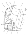
- Fig. 1 illustrates a broken, cut-off rear region of a car.
- the figure illustrates a view of the right inner side, which is a mirror image of the unillustrated left inner side.
- the illustration is simplified, for example, body interior structures, such as stiffeners and fasteners are not shown because their representation for the understanding of the invention is not required.
- the illustrated body section 1 has a roof 2, from the side of a B-pillar 3 leads down to a bottom group, not shown.
- a corresponding B-pillar would be conceivable on the broken-off side of the vehicle.
- the roof 2 merges at its rear edge into a rear window opening 4, in which a rear window 5 is inserted. Laterally, the rear window opening 4 ends at a C-pillar 6, which is at a distance from the B-pillar 3. Between the B pillar 3 and the C pillar 6, a rear, right side door 7 is hinged to the B pillar 3 in the known manner.
- right side door 7 is a rear seat 8, to which a seat 9 and a rear seat back 11 belong.
- the inside facing the interior of the side door 7 is provided with an inner lining 12 to which a door handle 13 is attached and in which an actuating pawl 14 is inserted to open the lock of the side door 7.
- the side door 7 contains above the inner lining 12 a window opening 15.
- a window opening 15 is a retractable in a known manner side window 16th
- the side door 7 is provided with a side window roller blind 17, the roller blind 18 is partially extended in the illustrations of Figure 1, so as to protect the rear region of the passenger compartment against lateral solar radiation.
- the blind sheet 18 passes through an existing below the window opening 15 slot 19th
- the vehicle can be equipped in both sides with window blinds, for example, in the front door area.
- Behind the rear seat back 11 is a rear shelf 21, which largely fills the space between the rear seat back 11 and the lower edge of the rear window 2.
- a housing 22 of a rear window blind 23 is arranged.
- the rear window roller blind 28 has a tensioned illustrated roller blind 29, which is pulled out of a slot 31 of the housing.
- the rear window shade 28 is configured as shown in FIG of the EP 0 240 747 C1 is shown in detail.
- window blinds shown serve to reduce the solar radiation into the interior of the motor vehicle in order to reduce the heating due to a greenhouse effect.
- FIG. 2 illustrates a block diagram for partially automated operation of the window blinds.
- the control of the rear window roller blind 28 is exemplified. It is understood that the explanation given applies mutatis mutandis to the side window blinds.
- the winding shaft is biased by means of a spring motor in the sense of winding up the roller blind 29.
- a drawbar 31 is attached, engage the pivot lever 32, which are mounted at 33 to the housing 22.
- the pivoting of the lever 32 is done by means of a not further shown electric motor via a corresponding transmission.
- the electric motor is a permanent-magnet DC motor whose direction of rotation is defined by the polarity of the connected power supply.
- the control contains an actual control unit or a control device 34 with a power supply input 35 to be connected to the vehicle electrical system and a current output 36 which is connected to the electric motor of the rear window roller blind 28 via a two-pole connecting cable 37.
- Two further inputs 38 and 39 are via corresponding Lines connected to two hand switches 41 and 42.
- the manual buttons 41 and 42 are, for example, buttons with a common rocker and intended to be operated manually by the user of the vehicle or another vehicle occupant.
- the two manual buttons 41 and 42 serve as signaling means to define the direction of movement or the state of the rear window roller blind 28 as a function of this state.
- Two further inputs 43 and 44 are connected via respective lines with a light sensor 45 and a temperature sensor 46.
- the light sensor 45 may consist of a photodiode or a cadmium sulfide photoresistor
- the temperature sensor may be a PTC or NTC resistor, a temperature sensitive resistor.
- a fifth input 47 is connected via a respective line to a switch 48 which is connected to the shift or gear selector lever of the motor vehicle.
- An input 48 communicates with a switch 51 which is actuated by the tailgate of the vehicle when the vehicle is a station wagon or a car with a large tailgate, in which the shown rear window is integrated in the tailgate.
- An input 52 is finally connected to the terminal +15 of the ignition or the ignition coil to signal the controller 34, whether the vehicle is in operation or not.
- Event-dependent should be understood to mean all events which are transmitted to the control device 34 and result from the operating state of the vehicle and environmental conditions, with the exception of the special request of vehicle occupants with regard to the operating position of the window blind or blinds in question.
- the user of the vehicle desires that the rear window roller blind 28 is extended, he briefly actuates the button 41, whereby a current pulse enters the input 39 of the control device 34. This then switches with the required polarity the supply voltage obtained via the input 35 to the output 36 so that the motor of the rear window roller blind 28 receives current with the required polarity via the two-pole line 37.
- the engine is set in motion, and pivots the two levers 32 in the sense of extending the roller blind 29th
- the controller 34 keeps powering on the engine of the rear window shade 28 for a predetermined time, which is certainly longer than the rear window shade 28 needed to fully extend.
- the duration for which the motor is supplied with power is independent of how long the user keeps pressing the button 41.
- the control device 35 switches on the voltage applied to the input 35 with a corresponding polarity to the output 36.
- the polarity is opposite to the polarity required to extend the roller blind 28.
- buttons 41 and 42 it may also be checked in advance if the vehicle is in operation.
- the signal is interrogated at the input 42.
- a voltage is present at terminal +15 of the ignition lock or the ignition coil to signal that the vehicle is in operation.
- manual operation of the rear window shade 28 may be disabled via the keys 41 and 42, i. the actuation of the button 41 and 42 does not lead to a current output of the control device 34 to the motor.
- the light sensor 45 is provided.
- the light sensor 45 is for example integrated into the parcel shelf 21 and aligned so that sunlight can fall on it. In this way, the light sensor 45 is able to signal the control device 34, whether a strong sunlight with the risk of heating the vehicle interior or not. If this situation occurs, which the control device 24 determines via the light sensor 45, the control device 34 automatically provides, without actuation of the pushbutton 41, for a current to be output at the output 36 for the motor of the rear window roller blind 28, with one polarity , which corresponds to the extension of the roller blind 29.
- the light sensor 45 may be located at a position that is always shaded by the roller blind 41 after the extension of the roller blind 29 regardless of the position of the sun. So that the roller blind 29 does not irritate the control device 34, the control device 34 only detects the occurrence of strong solar radiation with the aid of the light sensor 45. A renewed disappearance of sunlight as a result of the shadow through the roller blind 29 does not lead to retraction of the rear window blinds 28th
- the light sensor 45 it is also conceivable to accommodate the light sensor 45 at a location at which the sunlight can be continuously measured. In this way, it is possible to retract the rear window blind automatically 28 when the strong sunlight disappears at the window in question. It checks, similar to the extension, the Control device 34, the electrical signal reported by the light sensor 45 with a corresponding threshold and turns on the current at the output 36 for the corresponding time interval.
- the temperature sensor 46 signals the controller 34, the internal temperature of the vehicle. If the internal temperature is below a predetermined threshold in the control device 34, the control device 34 ignores a signal from the sun sensor 45 when it signals a strong solar radiation. Only when the internal temperature signaled by the temperature sensor 46 is exceeded, the control device 34 controls the rear window roller blind 28 in accordance with the signal coming from the light sensor 45, as described above.
- the extended rear window shade 28 not only prevents excessive sunlight from the rear window 5, but it also obstructs to some extent the rear view through the rear window 5. In normal driving this does not matter, but can significantly interfere when reversing.
- the position of the shift lever or the selector lever is therefore checked with the aid of the switch 48.
- the switch 48 is closed, causing the controller 34 to turn on the motor output at the current output 36, with a polarity that results in retraction of the blind.
- turning on the motor current at the output 36 as a result of closing the switch 48 may be made dependent on whether the controller 34 previously extended the rear window shade 28 or not.
- either the rear window blind 28 may remain open or be returned to the operating position prior to engagement of the reverse gear.
- a mechanical switch 48 can for sensing the shift lever or gear selector lever and a field plate or a Hall probe used in conjunction with a small permanent magnet.
- the signal provided by the switch 48 may also be an electrical signal supplied directly from the transmission control. In this case, the additional switch 48 is not needed.
- Vehicles with a large tailgate may damage the rear window blind 28 if the blind 29 is extended and the tailgate is opened.
- the switch 51 is present. The switch 51 is closed, for example, when the tailgate is unlocked. The rear window roller blind 28 is then retracted immediately and is already fully retracted before the tailgate reaches the fully open position.
- the controller 34 is conveniently based on a microprocessor that includes its own memory and its own program. Such a solution is advantageous if the vehicle can be retrofitted modular with window blinds. It is also readily understandable that the control device 34 can actuate not only the rear window roller blind 28 but also other side window roller blinds, in which case further light sensors 45 may be provided and the control device 34 has its own power output 36 for each drive motor of each side window roller blind.
- the described control device 34 with the connected signaling means can also be part of a central vehicle control 53, as indicated in highly schematic form in FIG.
- the central Vehicle control 53 has, for example, multipolar outputs 54, 55 or 56, via which motor actuators for valve adjustment, transmission actuators for shifting the transmission or door locks are actuated by way of example only.
- FIG. 4 shows a simplified flow diagram as it can proceed in the control device 34.
- the program begins at A and first queries in a query block 57 whether the ignition is on or not, which results in an interrogation of the signal state at the input 52.
- the switch 48 which signals the engagement of reverse gear, is checked. If the ignition is not turned on, this query may be skipped, i. if the reverse gear is engaged when the ignition is off, this has no effect on the condition of the rear window roller blind.
- the state of the switch 48 is checked in a query block 58 and leads to the above-mentioned consequences. If the switch 48 is not actuated, the program continues with inquiry blocks 59 and 61 in which the driver manually operated key 41 or 43 is checked. When the button 41 is pressed, the program proceeds to an instruction block 62 at which the current output 36 is caused to receive current from the current input 35 for a predetermined time with a polarity corresponding to the extension of the rear window shade 28. From there, the program goes to point B, where under certain circumstances, another program routine is jumped or returned to the starting point A.
- the program goes to a statement block 63, which in turn ensures that the current output 36 receives power from the power input 35, but with a polarity corresponding to the retraction of the roller blind 29. Subsequently, the program arrives at the program point B as mentioned previously.
- the signal which the light or sun sensor 45 supplies is checked in a query block 64. If a strong solar radiation is detected, the internal temperature is checked in a query block 65, which is detected by means of the temperature sensor 46. If the temperature is above a predetermined value, it is subsequently determined in a query block 66 whether the heater is turned on. If not, the program branches to the previously explained instruction block 62. Otherwise, it proceeds to an inquiry block 67 where the status of the tailgate switch 51 is checked. If the tailgate is closed, the program comes to the program point B, otherwise it branches to the instruction block 63 and opens the rear window roller blind 28th
- the program determines in the inquiry block 65 that the internal temperature per se is too low to operate the blind, the program branches to a query block 68 and checks the condition of the air conditioner. If the air conditioner is turned on, the instruction block 62 continues, otherwise the program returns to the beginning of the inquiry block 67.
- the program branches directly to the input of the query block 67.
- Fig. 5 shows the diagram of a very simple comfort control, which responds only to sunlight.
- the control device consists essentially only of a multi-pole switch 71 and a "smart" active sun sensor 72nd
- the sun sensor 72 is designed in such a way that there is no electrical connection between its power supply input 73 and its output 74 in the case of low light. On the other hand, if the solar radiation exceeds a certain threshold, the connection between the two terminals 73 and 74 becomes low-resistance for a limited time.
- the mechanical switch has a plurality of fixed contacts 75, 76, 77, 78, 79 and 81.
- the fixed contact 75 is connected to the output 74 of the sun sensor 72.
- the two fixed contacts 76 and 79 are together with the fixed Konak 81 on a vehicle mass 82, while the two fixed contacts 77 and 78 are connected together to the vehicle electrical system voltage.
- a movable contact 83 cooperates, which makes in the rest position of the switch 71 with the contact 75 actually makes an electrical contact.
- Another movable contact 84 is selectively engageable with the fixed contacts 76 and 77, while a movable contact 85 is to be connected to the fixed contacts 78 and 79.
- the two movable contacts 84 and 85 have no electrical connection with the associated fixed contacts 76 and 77 or 78 and 79 in the rest position.
- the switch 71 still contains a movable contact 86, which establishes an electrical connection with the stationary contact 81 in the rest position of the switch 71.
- the movable contacts 83 and 84 are common to an input terminal 87 of the drive motor 88 of the rear window roller blind, while the contacts 85 and 86 are located at another input terminal 89.
- the circuit works as follows:
- the circuit between the contact 77 and the contact 85 is also closed, while the circuits across the Contacts 83 and 86 are interrupted.
- the motor receives power via the movable contacts 84 and 85 in such a way that it is set in the sense of extending the rear window blind 28 in motion. He receives power until the user releases the switch 71, whereby the switch 71 returns to the rest position shown. The power supply to the motor 88 is thus initially switched off while the rear window roller blind 28 is retracted.
- the user operates the switch 71 in the opposite direction, i. the motor 88 receives power through the fixed contacts 77 and 79.
- the motor 88 contains current via the stationary contacts 75 and 81, in the sense of extending the roller blind.
- the time for which the engine 88 is energized controls a corresponding timer in the sun sensor 72nd
- the invention has been explained above with reference to window blinds.
- the invention is not limited to such applications. It can also be used to control roller blinds of cargo holds.
- the cargo door is monitored via a door contact, to drive back the cover when opening the cargo door. Closing should be done conveniently by the user and not automatically.
- a roller blind control for window blinds 17,28 of motor vehicles includes a control device 23,71.
- the control device 23, 71 receives signals from a switch 41, 42, which can be actuated manually by the driver or vehicle occupant, in order to be able to move in or out of the window blind 17, 28 arbitrarily.
- signaling means 45, 46, 48, 51 are provided which respond to other external events in order to bring the relevant window blind into a state which best fits the reported external event, irrespective of the operation by the driver.
Landscapes
- Engineering & Computer Science (AREA)
- Mechanical Engineering (AREA)
- Power-Operated Mechanisms For Wings (AREA)
- Operating, Guiding And Securing Of Roll- Type Closing Members (AREA)
Applications Claiming Priority (2)
| Application Number | Priority Date | Filing Date | Title |
|---|---|---|---|
| DE10041709A DE10041709A1 (de) | 2000-08-25 | 2000-08-25 | Rollosteuerung für Rollos in Kraftfahrzeugen |
| EP01967001A EP1218207B1 (fr) | 2000-08-25 | 2001-08-10 | Systeme de commande pour stores installes dans des vehicules automobiles |
Related Parent Applications (1)
| Application Number | Title | Priority Date | Filing Date |
|---|---|---|---|
| EP01967001A Division EP1218207B1 (fr) | 2000-08-25 | 2001-08-10 | Systeme de commande pour stores installes dans des vehicules automobiles |
Publications (3)
| Publication Number | Publication Date |
|---|---|
| EP1818200A2 true EP1818200A2 (fr) | 2007-08-15 |
| EP1818200A3 EP1818200A3 (fr) | 2008-01-23 |
| EP1818200B1 EP1818200B1 (fr) | 2009-03-11 |
Family
ID=7653721
Family Applications (3)
| Application Number | Title | Priority Date | Filing Date |
|---|---|---|---|
| EP07021610A Revoked EP1880884B1 (fr) | 2000-08-25 | 2001-08-10 | Commande de store pour stores dans des véhicules automobiles |
| EP07010657A Revoked EP1818200B1 (fr) | 2000-08-25 | 2001-08-10 | système de commande pour stores installés dans des véhicules automobiles |
| EP01967001A Expired - Lifetime EP1218207B1 (fr) | 2000-08-25 | 2001-08-10 | Systeme de commande pour stores installes dans des vehicules automobiles |
Family Applications Before (1)
| Application Number | Title | Priority Date | Filing Date |
|---|---|---|---|
| EP07021610A Revoked EP1880884B1 (fr) | 2000-08-25 | 2001-08-10 | Commande de store pour stores dans des véhicules automobiles |
Family Applications After (1)
| Application Number | Title | Priority Date | Filing Date |
|---|---|---|---|
| EP01967001A Expired - Lifetime EP1218207B1 (fr) | 2000-08-25 | 2001-08-10 | Systeme de commande pour stores installes dans des vehicules automobiles |
Country Status (6)
| Country | Link |
|---|---|
| US (1) | US20030141025A1 (fr) |
| EP (3) | EP1880884B1 (fr) |
| JP (1) | JP2004506565A (fr) |
| KR (1) | KR20020044568A (fr) |
| DE (4) | DE10041709A1 (fr) |
| WO (1) | WO2002016153A1 (fr) |
Families Citing this family (21)
| Publication number | Priority date | Publication date | Assignee | Title |
|---|---|---|---|---|
| DE10248003A1 (de) * | 2002-10-15 | 2004-04-29 | Bayerische Motoren Werke Ag | Automatischer Sonnenschutz für Fahrzeuge |
| DE10319893B4 (de) * | 2003-04-28 | 2015-11-19 | Brose Fahrzeugteile Gmbh & Co. Kommanditgesellschaft, Coburg | Steuereinrichtung für Sonnenschutzrollos und verstellbare Fensterscheiben von Kraftfahrzeugen |
| US7401840B2 (en) * | 2006-05-09 | 2008-07-22 | Gm Global Technology Operations, Inc. | Window shade |
| DE202006020188U1 (de) * | 2006-09-25 | 2007-11-29 | Maxon Motor Gmbh | Antriebsvorrichtung für eine Laderaumabdeckung |
| FR2938471B1 (fr) * | 2008-11-18 | 2013-05-24 | Peugeot Citroen Automobiles Sa | Dispositif de retenue d'un rideau pare-soleil pour vitre telle que celle d'un vehicule |
| US20110068601A1 (en) * | 2009-09-23 | 2011-03-24 | Gm Global Technology Operations, Inc. | Vehicle Solar Load Reduction System |
| US8701737B2 (en) | 2009-11-09 | 2014-04-22 | LDM Products, Inc | Retractable computer rack aisle roof |
| DE102010007505A1 (de) * | 2010-02-11 | 2011-08-11 | Bayerische Motoren Werke Aktiengesellschaft, 80809 | Kraftfahrzeug mit mindestens einem Sonnenschutzrollo |
| DE102010052743B4 (de) | 2010-11-26 | 2016-10-27 | Audi Ag | Kraftfahrzeug mit werkzeuglos entnehmbarem Bauteil sowie Hutablage für ein Kraftfahrzeug |
| FR3005899B1 (fr) * | 2013-05-23 | 2016-03-18 | Peugeot Citroen Automobiles Sa | Occultation d'une surface vitree de vehicule |
| US9079479B2 (en) * | 2013-10-21 | 2015-07-14 | Liang Chen | Automated sunshade |
| KR101534728B1 (ko) | 2013-12-20 | 2015-07-07 | 현대자동차 주식회사 | 차량의 커튼 제어 장치 |
| US10577858B2 (en) * | 2014-12-16 | 2020-03-03 | Current Products Corp. | Remote controlled motorized wand for controlling blinds |
| DE102015220436A1 (de) * | 2015-10-20 | 2017-04-20 | Bayerische Motoren Werke Aktiengesellschaft | Instrumententafel |
| CN107097613B (zh) * | 2017-05-17 | 2023-09-12 | 南京工业大学 | 一种低能耗车辆 |
| US20180361831A1 (en) * | 2017-06-14 | 2018-12-20 | Ford Global Technologies, Llc | Vehicle shade assembly |
| GB2566511B (en) * | 2017-09-15 | 2019-12-18 | Detroit Electric Ev Tech Zhejiang Limited | Automated screening arrangement for vehicle and method |
| WO2019053679A2 (fr) * | 2017-09-15 | 2019-03-21 | Detroit Electric Ev Technologies (Zhejiang) Limited | Agencement de criblage automatique pour véhicule et procédé associé |
| CN111301121B (zh) * | 2018-12-11 | 2023-12-01 | 上海汽车集团股份有限公司 | 一种控制车窗透热量的方法和装置 |
| FR3107012B1 (fr) * | 2020-02-11 | 2022-12-16 | Dav | Interface pour la commande d’au moins une fonction d’un organe de véhicule automobile |
| US11858318B2 (en) | 2021-03-09 | 2024-01-02 | GM Global Technology Operations LLC | Vehicular power shade control system and method |
Citations (1)
| Publication number | Priority date | Publication date | Assignee | Title |
|---|---|---|---|---|
| EP0240747A2 (fr) | 1986-04-11 | 1987-10-14 | Baumeister & Ostler GmbH & Co. | Stores sans guidage, notamment pour véhicules automobiles |
Family Cites Families (21)
| Publication number | Priority date | Publication date | Assignee | Title |
|---|---|---|---|---|
| JPH0645291B2 (ja) * | 1985-09-20 | 1994-06-15 | 日本電装株式会社 | 車両用制御システム |
| JPH0427686Y2 (fr) * | 1987-05-23 | 1992-07-03 | ||
| GB2214474A (en) * | 1988-01-21 | 1989-09-06 | Al Dujaili Mohammed Jamal | Automatic vehicle windscreen sunlight shade system |
| JPH02127561U (fr) * | 1989-03-30 | 1990-10-22 | ||
| DE3920404A1 (de) * | 1989-06-22 | 1991-01-03 | Bayerische Motoren Werke Ag | Steuervorrichtung fuer ein stellglied |
| JPH0361119A (ja) * | 1989-07-31 | 1991-03-15 | Nissan Motor Co Ltd | 車両用ウインドウガラスの透過率制御装置 |
| IT1236964B (it) * | 1989-10-18 | 1993-05-07 | Iti Ind S R L | Gruppo di motorizzazione, per l'azionamento di tende parasole per autoveicoli. |
| US5042866A (en) * | 1990-10-15 | 1991-08-27 | Cody Ernest W | Automotive sun screen |
| US5054686A (en) * | 1990-11-05 | 1991-10-08 | Prospect Corporation | Automobile environment management system |
| JPH0479718U (fr) * | 1990-11-27 | 1992-07-10 | ||
| JPH055524U (ja) * | 1991-07-04 | 1993-01-26 | アラコ株式会社 | 車両用カーテン装置 |
| GB2263678A (en) * | 1992-01-28 | 1993-08-04 | Wang Wen Hsu | Fully automatic car window shade |
| JPH0586625U (ja) * | 1992-04-28 | 1993-11-22 | 三菱自動車工業株式会社 | ウインドシールドシャッタ |
| JP3243308B2 (ja) * | 1992-12-02 | 2002-01-07 | アスモ株式会社 | 車両用カーテン開閉装置 |
| US5298732A (en) * | 1993-02-18 | 1994-03-29 | Emee, Inc. | Automatic visor for continuously repositioning a shading object to shade a designated location from a direct radiation source |
| JPH07139418A (ja) * | 1993-11-19 | 1995-05-30 | Hitachi Ltd | 自動車用総合制御装置 |
| JPH0740794A (ja) * | 1993-07-26 | 1995-02-10 | Hitachi Ltd | 自動車用制御ユニット |
| JP3246833B2 (ja) * | 1994-07-08 | 2002-01-15 | 株式会社日立製作所 | 自動車制御装置及び自動車制御方法 |
| JP2000108660A (ja) * | 1998-10-05 | 2000-04-18 | Yoshikazu Ichiyama | 外部視認性を向上する乗り物及び防眩装置及び方法 |
| DE19856741C2 (de) * | 1998-12-09 | 2001-02-01 | Baumeister & Ostler Gmbh Co | Laderaumabdeckung bzw. Hutablage mit beweglichen Eckstücken |
| DE10014760B4 (de) * | 2000-03-24 | 2004-02-12 | Bos Gmbh & Co. Kg | Heckscheibenrollo mit gefederten Rollen |
-
2000
- 2000-08-25 DE DE10041709A patent/DE10041709A1/de not_active Ceased
-
2001
- 2001-08-10 EP EP07021610A patent/EP1880884B1/fr not_active Revoked
- 2001-08-10 EP EP07010657A patent/EP1818200B1/fr not_active Revoked
- 2001-08-10 WO PCT/DE2001/003090 patent/WO2002016153A1/fr active IP Right Grant
- 2001-08-10 US US10/111,343 patent/US20030141025A1/en not_active Abandoned
- 2001-08-10 EP EP01967001A patent/EP1218207B1/fr not_active Expired - Lifetime
- 2001-08-10 DE DE50114089T patent/DE50114089D1/de not_active Expired - Lifetime
- 2001-08-10 KR KR1020027005238A patent/KR20020044568A/ko not_active Application Discontinuation
- 2001-08-10 DE DE50114802T patent/DE50114802D1/de not_active Expired - Lifetime
- 2001-08-10 JP JP2002521049A patent/JP2004506565A/ja active Pending
- 2001-08-10 DE DE50114772T patent/DE50114772D1/de not_active Expired - Lifetime
Patent Citations (1)
| Publication number | Priority date | Publication date | Assignee | Title |
|---|---|---|---|---|
| EP0240747A2 (fr) | 1986-04-11 | 1987-10-14 | Baumeister & Ostler GmbH & Co. | Stores sans guidage, notamment pour véhicules automobiles |
Also Published As
| Publication number | Publication date |
|---|---|
| KR20020044568A (ko) | 2002-06-15 |
| JP2004506565A (ja) | 2004-03-04 |
| DE50114089D1 (de) | 2008-08-21 |
| EP1218207A1 (fr) | 2002-07-03 |
| EP1880884B1 (fr) | 2009-03-25 |
| EP1880884A2 (fr) | 2008-01-23 |
| EP1880884A3 (fr) | 2008-02-06 |
| DE50114802D1 (de) | 2009-05-07 |
| US20030141025A1 (en) | 2003-07-31 |
| DE10041709A1 (de) | 2002-05-16 |
| EP1818200A3 (fr) | 2008-01-23 |
| WO2002016153A1 (fr) | 2002-02-28 |
| EP1218207B1 (fr) | 2008-07-09 |
| EP1818200B1 (fr) | 2009-03-11 |
| DE50114772D1 (de) | 2009-04-23 |
Similar Documents
| Publication | Publication Date | Title |
|---|---|---|
| EP1880884B1 (fr) | Commande de store pour stores dans des véhicules automobiles | |
| DE19600524B4 (de) | Schloß, insbesondere für Kraftfahrzeugtüren | |
| DE112008002316B4 (de) | System und Verfahren zum dynamischen Bremsen eines Fahrzeugverschlusssystems | |
| DE19803709C2 (de) | Automatisches Öffnungs- und Schließsystem für eine Fahrzeugschiebetür | |
| DE4132499B4 (de) | Betätigungseinrichtung für Verstelleinrichtungen in einem Kraftfahrzeug | |
| DE102016210251A1 (de) | Schließzylinder-Freigabemechanismus für Fahrzeugschließverriegelungen, Verriegelungsanordnung damit und Verfahren zum mechanischen Freigeben einer Fahrzeugschließverriegelung | |
| EP3303741B1 (fr) | Serrure de porte de véhicule | |
| DE102020109147A1 (de) | Kraft-stellantrieb mit nockengetriebenem doppelkabel-betätigungsmechanismus zur verwendung mit einer fahrzeug-verschlussverriegelungsanordnung | |
| EP3303742B1 (fr) | Procédé de commande d'une serrure de porte de véhicule | |
| EP2336465A2 (fr) | Circuit et procédé de protection contre l'ouverture involontaire d'une porte de véhicule | |
| DE4329157C2 (de) | Spiegelanordnung mit einer einziehbaren Spiegeleinrichtung für ein Kraftfahrzeug mit Hecktüre | |
| EP1199619A2 (fr) | Système d'entraínement d'équipements de store roulant pour véhicule | |
| EP1913222B1 (fr) | Procede de positionnement d'une unite mobile dans un vehicule automobile | |
| EP1262349B1 (fr) | Procédé pour contrôler un store pour fenêtre | |
| DE102007055115A1 (de) | Öffnungsschutz, insbesondere von Schiebetüren | |
| DE10222029B3 (de) | Komfortlüftung für Kraftfahrzeuge | |
| DE19831722C2 (de) | Innenlichtschaltung | |
| EP0416384B1 (fr) | Dispositif de commande pour un toit à ventilation d'un véhicule | |
| DE10234782A1 (de) | Kraftfahrzeugschloß | |
| DE10262292B4 (de) | Laderaumabdeckung für einen Laderaum eines Kraftfahrzeuges | |
| DE2854670A1 (de) | Schaltanordnung fuer einen aus einer spannungsquelle gespeisten drehrichtungsumkehrbaren elektromotor zum antrieb einer fensterhebeanlage in kraftfahrzeugen | |
| DE3840763C2 (fr) | ||
| DE29921946U1 (de) | Schaltvorrichtung für einen Diebstahlsicherungsantrieb eines Kraftfahrzeugtürverschlusses | |
| EP1388448B1 (fr) | Procédé pour déplacer un toit coulissant en plusieurs parties pour un véhicule | |
| DE102005058144B4 (de) | Toröffnungssystem für ein Kraftfahrzeug |
Legal Events
| Date | Code | Title | Description |
|---|---|---|---|
| PUAI | Public reference made under article 153(3) epc to a published international application that has entered the european phase |
Free format text: ORIGINAL CODE: 0009012 |
|
| 17P | Request for examination filed |
Effective date: 20070530 |
|
| AC | Divisional application: reference to earlier application |
Ref document number: 1218207 Country of ref document: EP Kind code of ref document: P |
|
| AK | Designated contracting states |
Kind code of ref document: A2 Designated state(s): DE FR GB IT |
|
| PUAL | Search report despatched |
Free format text: ORIGINAL CODE: 0009013 |
|
| AK | Designated contracting states |
Kind code of ref document: A3 Designated state(s): DE FR GB IT |
|
| RIC1 | Information provided on ipc code assigned before grant |
Ipc: B60R 5/04 20060101ALI20071214BHEP Ipc: B60J 1/20 20060101AFI20070710BHEP |
|
| 17Q | First examination report despatched |
Effective date: 20080402 |
|
| AKX | Designation fees paid |
Designated state(s): DE FR GB IT |
|
| GRAP | Despatch of communication of intention to grant a patent |
Free format text: ORIGINAL CODE: EPIDOSNIGR1 |
|
| GRAS | Grant fee paid |
Free format text: ORIGINAL CODE: EPIDOSNIGR3 |
|
| GRAA | (expected) grant |
Free format text: ORIGINAL CODE: 0009210 |
|
| AC | Divisional application: reference to earlier application |
Ref document number: 1218207 Country of ref document: EP Kind code of ref document: P |
|
| AK | Designated contracting states |
Kind code of ref document: B1 Designated state(s): DE FR GB IT |
|
| REG | Reference to a national code |
Ref country code: GB Ref legal event code: FG4D Free format text: NOT ENGLISH |
|
| REF | Corresponds to: |
Ref document number: 50114772 Country of ref document: DE Date of ref document: 20090423 Kind code of ref document: P |
|
| PLBI | Opposition filed |
Free format text: ORIGINAL CODE: 0009260 |
|
| 26 | Opposition filed |
Opponent name: BROSE FAHRZEUGTEILE GMBH & CO. KG, COBURG Effective date: 20091209 |
|
| PLAX | Notice of opposition and request to file observation + time limit sent |
Free format text: ORIGINAL CODE: EPIDOSNOBS2 |
|
| GBPC | Gb: european patent ceased through non-payment of renewal fee |
Effective date: 20090810 |
|
| PLAF | Information modified related to communication of a notice of opposition and request to file observations + time limit |
Free format text: ORIGINAL CODE: EPIDOSCOBS2 |
|
| REG | Reference to a national code |
Ref country code: FR Ref legal event code: ST Effective date: 20100430 |
|
| PG25 | Lapsed in a contracting state [announced via postgrant information from national office to epo] |
Ref country code: FR Free format text: LAPSE BECAUSE OF NON-PAYMENT OF DUE FEES Effective date: 20090831 |
|
| PLBB | Reply of patent proprietor to notice(s) of opposition received |
Free format text: ORIGINAL CODE: EPIDOSNOBS3 |
|
| PG25 | Lapsed in a contracting state [announced via postgrant information from national office to epo] |
Ref country code: GB Free format text: LAPSE BECAUSE OF NON-PAYMENT OF DUE FEES Effective date: 20090810 |
|
| PG25 | Lapsed in a contracting state [announced via postgrant information from national office to epo] |
Ref country code: IT Free format text: LAPSE BECAUSE OF FAILURE TO SUBMIT A TRANSLATION OF THE DESCRIPTION OR TO PAY THE FEE WITHIN THE PRESCRIBED TIME-LIMIT Effective date: 20090311 |
|
| PGFP | Annual fee paid to national office [announced via postgrant information from national office to epo] |
Ref country code: DE Payment date: 20110831 Year of fee payment: 11 |
|
| PLAY | Examination report in opposition despatched + time limit |
Free format text: ORIGINAL CODE: EPIDOSNORE2 |
|
| PLBC | Reply to examination report in opposition received |
Free format text: ORIGINAL CODE: EPIDOSNORE3 |
|
| RDAF | Communication despatched that patent is revoked |
Free format text: ORIGINAL CODE: EPIDOSNREV1 |
|
| REG | Reference to a national code |
Ref country code: DE Ref legal event code: R103 Ref document number: 50114772 Country of ref document: DE Ref country code: DE Ref legal event code: R064 Ref document number: 50114772 Country of ref document: DE |
|
| RDAG | Patent revoked |
Free format text: ORIGINAL CODE: 0009271 |
|
| STAA | Information on the status of an ep patent application or granted ep patent |
Free format text: STATUS: PATENT REVOKED |
|
| 27W | Patent revoked |
Effective date: 20121206 |
|
| REG | Reference to a national code |
Ref country code: DE Ref legal event code: R107 Ref document number: 50114772 Country of ref document: DE Effective date: 20130926 |