EP1817793B1 - Verfahren zur herstellung von koplanaren chipgehäusen in wafergrösse - Google Patents
Verfahren zur herstellung von koplanaren chipgehäusen in wafergrösse Download PDFInfo
- Publication number
- EP1817793B1 EP1817793B1 EP05808156A EP05808156A EP1817793B1 EP 1817793 B1 EP1817793 B1 EP 1817793B1 EP 05808156 A EP05808156 A EP 05808156A EP 05808156 A EP05808156 A EP 05808156A EP 1817793 B1 EP1817793 B1 EP 1817793B1
- Authority
- EP
- European Patent Office
- Prior art keywords
- chip
- chips
- wafer
- forming
- areas
- Prior art date
- Legal status (The legal status is an assumption and is not a legal conclusion. Google has not performed a legal analysis and makes no representation as to the accuracy of the status listed.)
- Not-in-force
Links
- 238000000034 method Methods 0.000 title claims abstract description 96
- 239000000758 substrate Substances 0.000 claims abstract description 108
- 239000010410 layer Substances 0.000 claims description 83
- 239000011800 void material Substances 0.000 claims description 25
- 238000002955 isolation Methods 0.000 claims description 9
- 230000015572 biosynthetic process Effects 0.000 claims description 8
- 238000002161 passivation Methods 0.000 claims description 7
- 238000005530 etching Methods 0.000 claims description 6
- 239000012790 adhesive layer Substances 0.000 claims description 4
- 239000011248 coating agent Substances 0.000 claims description 4
- 238000000576 coating method Methods 0.000 claims description 4
- 238000000151 deposition Methods 0.000 claims description 4
- 238000000059 patterning Methods 0.000 claims description 3
- 230000010354 integration Effects 0.000 abstract description 8
- 239000000463 material Substances 0.000 abstract description 8
- 235000012431 wafers Nutrition 0.000 description 118
- XUIMIQQOPSSXEZ-UHFFFAOYSA-N Silicon Chemical compound [Si] XUIMIQQOPSSXEZ-UHFFFAOYSA-N 0.000 description 16
- 229910052710 silicon Inorganic materials 0.000 description 16
- 239000010703 silicon Substances 0.000 description 16
- 239000004065 semiconductor Substances 0.000 description 12
- 239000000969 carrier Substances 0.000 description 7
- 150000004767 nitrides Chemical class 0.000 description 7
- 150000001875 compounds Chemical class 0.000 description 5
- 238000005520 cutting process Methods 0.000 description 5
- 239000003990 capacitor Substances 0.000 description 4
- 238000012545 processing Methods 0.000 description 4
- JBRZTFJDHDCESZ-UHFFFAOYSA-N AsGa Chemical compound [As]#[Ga] JBRZTFJDHDCESZ-UHFFFAOYSA-N 0.000 description 3
- 238000013461 design Methods 0.000 description 3
- 238000012544 monitoring process Methods 0.000 description 3
- 229920002120 photoresistant polymer Polymers 0.000 description 3
- 238000012360 testing method Methods 0.000 description 3
- 229910001218 Gallium arsenide Inorganic materials 0.000 description 2
- UHYPYGJEEGLRJD-UHFFFAOYSA-N cadmium(2+);selenium(2-) Chemical compound [Se-2].[Cd+2] UHYPYGJEEGLRJD-UHFFFAOYSA-N 0.000 description 2
- 229910052732 germanium Inorganic materials 0.000 description 2
- GNPVGFCGXDBREM-UHFFFAOYSA-N germanium atom Chemical compound [Ge] GNPVGFCGXDBREM-UHFFFAOYSA-N 0.000 description 2
- 229910021480 group 4 element Inorganic materials 0.000 description 2
- 238000001465 metallisation Methods 0.000 description 2
- 238000012546 transfer Methods 0.000 description 2
- 230000003245 working effect Effects 0.000 description 2
- 239000000853 adhesive Substances 0.000 description 1
- 230000001070 adhesive effect Effects 0.000 description 1
- 230000003247 decreasing effect Effects 0.000 description 1
- 230000008021 deposition Effects 0.000 description 1
- 238000001312 dry etching Methods 0.000 description 1
- 239000011521 glass Substances 0.000 description 1
- 229910021478 group 5 element Inorganic materials 0.000 description 1
- 229910021476 group 6 element Inorganic materials 0.000 description 1
- 150000002500 ions Chemical class 0.000 description 1
- 238000003698 laser cutting Methods 0.000 description 1
- 238000001459 lithography Methods 0.000 description 1
- 238000004519 manufacturing process Methods 0.000 description 1
- 229910044991 metal oxide Inorganic materials 0.000 description 1
- 150000004706 metal oxides Chemical class 0.000 description 1
- 238000001020 plasma etching Methods 0.000 description 1
- 238000005498 polishing Methods 0.000 description 1
- 229910021420 polycrystalline silicon Inorganic materials 0.000 description 1
- 238000002360 preparation method Methods 0.000 description 1
- HBMJWWWQQXIZIP-UHFFFAOYSA-N silicon carbide Chemical compound [Si+]#[C-] HBMJWWWQQXIZIP-UHFFFAOYSA-N 0.000 description 1
- 238000001039 wet etching Methods 0.000 description 1
Images


Classifications
-
- H—ELECTRICITY
- H01—ELECTRIC ELEMENTS
- H01L—SEMICONDUCTOR DEVICES NOT COVERED BY CLASS H10
- H01L21/00—Processes or apparatus adapted for the manufacture or treatment of semiconductor or solid state devices or of parts thereof
- H01L21/02—Manufacture or treatment of semiconductor devices or of parts thereof
- H01L21/04—Manufacture or treatment of semiconductor devices or of parts thereof the devices having potential barriers, e.g. a PN junction, depletion layer or carrier concentration layer
- H01L21/18—Manufacture or treatment of semiconductor devices or of parts thereof the devices having potential barriers, e.g. a PN junction, depletion layer or carrier concentration layer the devices having semiconductor bodies comprising elements of Group IV of the Periodic Table or AIIIBV compounds with or without impurities, e.g. doping materials
- H01L21/30—Treatment of semiconductor bodies using processes or apparatus not provided for in groups H01L21/20 - H01L21/26
-
- H—ELECTRICITY
- H01—ELECTRIC ELEMENTS
- H01L—SEMICONDUCTOR DEVICES NOT COVERED BY CLASS H10
- H01L23/00—Details of semiconductor or other solid state devices
- H01L23/52—Arrangements for conducting electric current within the device in operation from one component to another, i.e. interconnections, e.g. wires, lead frames
- H01L23/538—Arrangements for conducting electric current within the device in operation from one component to another, i.e. interconnections, e.g. wires, lead frames the interconnection structure between a plurality of semiconductor chips being formed on, or in, insulating substrates
- H01L23/5389—Arrangements for conducting electric current within the device in operation from one component to another, i.e. interconnections, e.g. wires, lead frames the interconnection structure between a plurality of semiconductor chips being formed on, or in, insulating substrates the chips being integrally enclosed by the interconnect and support structures
-
- H—ELECTRICITY
- H01—ELECTRIC ELEMENTS
- H01L—SEMICONDUCTOR DEVICES NOT COVERED BY CLASS H10
- H01L21/00—Processes or apparatus adapted for the manufacture or treatment of semiconductor or solid state devices or of parts thereof
- H01L21/02—Manufacture or treatment of semiconductor devices or of parts thereof
- H01L21/04—Manufacture or treatment of semiconductor devices or of parts thereof the devices having potential barriers, e.g. a PN junction, depletion layer or carrier concentration layer
- H01L21/50—Assembly of semiconductor devices using processes or apparatus not provided for in a single one of the subgroups H01L21/06 - H01L21/326, e.g. sealing of a cap to a base of a container
- H01L21/52—Mounting semiconductor bodies in containers
-
- H—ELECTRICITY
- H01—ELECTRIC ELEMENTS
- H01L—SEMICONDUCTOR DEVICES NOT COVERED BY CLASS H10
- H01L21/00—Processes or apparatus adapted for the manufacture or treatment of semiconductor or solid state devices or of parts thereof
- H01L21/70—Manufacture or treatment of devices consisting of a plurality of solid state components formed in or on a common substrate or of parts thereof; Manufacture of integrated circuit devices or of parts thereof
- H01L21/77—Manufacture or treatment of devices consisting of a plurality of solid state components or integrated circuits formed in, or on, a common substrate
- H01L21/78—Manufacture or treatment of devices consisting of a plurality of solid state components or integrated circuits formed in, or on, a common substrate with subsequent division of the substrate into plural individual devices
-
- H—ELECTRICITY
- H01—ELECTRIC ELEMENTS
- H01L—SEMICONDUCTOR DEVICES NOT COVERED BY CLASS H10
- H01L23/00—Details of semiconductor or other solid state devices
- H01L23/12—Mountings, e.g. non-detachable insulating substrates
-
- H—ELECTRICITY
- H01—ELECTRIC ELEMENTS
- H01L—SEMICONDUCTOR DEVICES NOT COVERED BY CLASS H10
- H01L23/00—Details of semiconductor or other solid state devices
- H01L23/12—Mountings, e.g. non-detachable insulating substrates
- H01L23/14—Mountings, e.g. non-detachable insulating substrates characterised by the material or its electrical properties
- H01L23/147—Semiconductor insulating substrates
-
- H—ELECTRICITY
- H01—ELECTRIC ELEMENTS
- H01L—SEMICONDUCTOR DEVICES NOT COVERED BY CLASS H10
- H01L23/00—Details of semiconductor or other solid state devices
- H01L23/48—Arrangements for conducting electric current to or from the solid state body in operation, e.g. leads, terminal arrangements ; Selection of materials therefor
-
- H—ELECTRICITY
- H01—ELECTRIC ELEMENTS
- H01L—SEMICONDUCTOR DEVICES NOT COVERED BY CLASS H10
- H01L23/00—Details of semiconductor or other solid state devices
- H01L23/52—Arrangements for conducting electric current within the device in operation from one component to another, i.e. interconnections, e.g. wires, lead frames
- H01L23/538—Arrangements for conducting electric current within the device in operation from one component to another, i.e. interconnections, e.g. wires, lead frames the interconnection structure between a plurality of semiconductor chips being formed on, or in, insulating substrates
- H01L23/5385—Assembly of a plurality of insulating substrates
-
- H—ELECTRICITY
- H01—ELECTRIC ELEMENTS
- H01L—SEMICONDUCTOR DEVICES NOT COVERED BY CLASS H10
- H01L2221/00—Processes or apparatus adapted for the manufacture or treatment of semiconductor or solid state devices or of parts thereof covered by H01L21/00
- H01L2221/67—Apparatus for handling semiconductor or electric solid state devices during manufacture or treatment thereof; Apparatus for handling wafers during manufacture or treatment of semiconductor or electric solid state devices or components; Apparatus not specifically provided for elsewhere
- H01L2221/683—Apparatus for handling semiconductor or electric solid state devices during manufacture or treatment thereof; Apparatus for handling wafers during manufacture or treatment of semiconductor or electric solid state devices or components; Apparatus not specifically provided for elsewhere for supporting or gripping
- H01L2221/68304—Apparatus for handling semiconductor or electric solid state devices during manufacture or treatment thereof; Apparatus for handling wafers during manufacture or treatment of semiconductor or electric solid state devices or components; Apparatus not specifically provided for elsewhere for supporting or gripping using temporarily an auxiliary support
- H01L2221/68318—Auxiliary support including means facilitating the separation of a device or wafer from the auxiliary support
- H01L2221/68322—Auxiliary support including means facilitating the selective separation of some of a plurality of devices from the auxiliary support
-
- H—ELECTRICITY
- H01—ELECTRIC ELEMENTS
- H01L—SEMICONDUCTOR DEVICES NOT COVERED BY CLASS H10
- H01L2221/00—Processes or apparatus adapted for the manufacture or treatment of semiconductor or solid state devices or of parts thereof covered by H01L21/00
- H01L2221/67—Apparatus for handling semiconductor or electric solid state devices during manufacture or treatment thereof; Apparatus for handling wafers during manufacture or treatment of semiconductor or electric solid state devices or components; Apparatus not specifically provided for elsewhere
- H01L2221/683—Apparatus for handling semiconductor or electric solid state devices during manufacture or treatment thereof; Apparatus for handling wafers during manufacture or treatment of semiconductor or electric solid state devices or components; Apparatus not specifically provided for elsewhere for supporting or gripping
- H01L2221/68304—Apparatus for handling semiconductor or electric solid state devices during manufacture or treatment thereof; Apparatus for handling wafers during manufacture or treatment of semiconductor or electric solid state devices or components; Apparatus not specifically provided for elsewhere for supporting or gripping using temporarily an auxiliary support
- H01L2221/68345—Apparatus for handling semiconductor or electric solid state devices during manufacture or treatment thereof; Apparatus for handling wafers during manufacture or treatment of semiconductor or electric solid state devices or components; Apparatus not specifically provided for elsewhere for supporting or gripping using temporarily an auxiliary support used as a support during the manufacture of self supporting substrates
-
- H—ELECTRICITY
- H01—ELECTRIC ELEMENTS
- H01L—SEMICONDUCTOR DEVICES NOT COVERED BY CLASS H10
- H01L2924/00—Indexing scheme for arrangements or methods for connecting or disconnecting semiconductor or solid-state bodies as covered by H01L24/00
- H01L2924/0001—Technical content checked by a classifier
- H01L2924/0002—Not covered by any one of groups H01L24/00, H01L24/00 and H01L2224/00
-
- H—ELECTRICITY
- H01—ELECTRIC ELEMENTS
- H01L—SEMICONDUCTOR DEVICES NOT COVERED BY CLASS H10
- H01L2924/00—Indexing scheme for arrangements or methods for connecting or disconnecting semiconductor or solid-state bodies as covered by H01L24/00
- H01L2924/10—Details of semiconductor or other solid state devices to be connected
- H01L2924/11—Device type
- H01L2924/14—Integrated circuits
- H01L2924/143—Digital devices
- H01L2924/1433—Application-specific integrated circuit [ASIC]
Definitions
- the present invention relates generally to a multi-chip wafer level package, and more particularly, to methods for forming a multi-chip wafer-level packages using partial wafer bonding and partial wafer dicing techniques.
- CMOS complementary metal oxide
- SoC embedded system-on-a-chip
- interconnections among stacked chips are formed at the edges of each chip using a wire bond or a tag bond.
- Stacked chips that are used in portable devices must be thinned down in order to fit into the limited space available. As the number of stacked chips increases, the thickness of the chips must be reduced. The number of chips that can be stacked is determined by the maximum available space and the minimum chip thickness.
- US 4,907,062 discloses a device equivalent to wafer-scale integrated device is achieved by employing multiple IC chips installed on a silicon wafer.
- US 5,091,331 discloses a process including forming peaks and valleys in a bonding surface of a first wafer so that the peaks are at the scribe lines which define dice.
- Exemplary embodiments of the present invention include methods for forming multi-chip wafer-level chip packages without the need for planarizing a bonded chip surface to form global interconnects and for facilitating the integration of chips fabricated by different processing steps and with different materials.
- An exemplary embodiment relates to a method of forming a multi-chip wafer-level package.
- the method includes forming a plurality of different-type chips on a plurality of chip substrates, wherein each of the plurality of chip substrates is used to form only one-type of chip, detaching said plurality of different-type chips from said plurality of chip substrates, forming pockets in a carrier substrate, wherein each of the pockets holds one of said plurality of different-type chips, and mounting said plurality of chips into their corresponding pockets in the carrier substrate such that a top surface of said plurality of chips is substantially co-planar with a top surface of the carrier substrate.
- the different-type chips may be Memory chips, Logic chips, MEMs devices, RF circuits or passive devices.
- the step of forming a plurality of the chips on a plurality of chip substrates may also include bonding a wafer to STI (shallow trench isolation) regions in each of the chip substrates such that voids are formed adjacent to the STI regions and between the wafer and a chip substrate, wherein areas in the wafer above the STI regions define inter-chip areas and areas in the wafer above the void define chip areas.
- a discrete device may be formed in the inter-chip areas of the chip substrate, wherein the discrete device may be an inductor, a decoupling capacitor, or electrostatic discharge (ESD) diode.
- the method may also include patterning a dielectric layer on the chip substrate, etching the pattern dielectric layer to define off-chip areas, forming STI regions in the off-chip areas, and removing the dielectric layer between the off-chip areas.
- the method may also include thinning said wafer, forming devices in said thinned wafer, forming BEOL (Back-End-Of-Line) interconnects on said thinned wafer, and forming finishing devices and interconnects in the chip areas to complete the formation of said plurality of chips.
- BEOL Back-End-Of-Line
- the step of detaching said plurality of chips from said plurality of chip substrates may also include coating a top surface of said thinned wafer with a passivation layer, and dicing, or etching, a channel through the chip areas of said thinned wafer to the voids, thereby detaching said plurality of chips from said plurality of chip substrates.
- the step of forming pockets in the carrier substrate may also include bonding a wafer to STI regions in the carrier substrate such that voids are formed adjacent to the STI regions and between the wafer and the carrier substrate, wherein areas in the wafer above the STI regions define inter-chip areas and areas in the wafer above the voids define chip areas.
- the step of mounting said plurality of chips into their corresponding pockets may also include depositing a dielectric layer in the chip areas having a substantially same thickness as the voids, and aligning said plurality of chips within their corresponding pockets.
- Another exemplary embodiment relates to a method of forming a multi-chip wafer level package.
- the method includes forming a plurality of same or different-type chips on a corresponding chip substrate, detaching said plurality of chips from said corresponding chip substrate, forming a plurality of pockets on a carrier substrate such that each of the plurality of pockets holds a predetermined-type chip, selecting chips from the plurality of same or different-type chips that correspond to the predetermined-type chips for each of the plurality of pockets, and mounting the selected chips into their corresponding pocket such that a top surface of the selected chips is substantially co-planar with a top surface of the carrier substrate.
- a method for forming a multi-chip wafer level package comprising the steps of: forming shallow trench isolation (STI) regions in a carrier substrate; bonding a wafer to the STI regions in the carrier substrate such that voids are formed adjacent to the STI regions and between the wafer and the carrier substrate, wherein areas in the wafer above the STI regions define inter-chip areas and areas in the wafer above the voids define chip areas.
- STI shallow trench isolation
- Exemplary embodiments of the invention as described herein provide low-cost methods for fabricating multi-chip wafer-level packages, where both chips and carrier are formed using "partial wafer bonding" and "partial wafer dicing” techniques.
- the use of partial wafer bonding allows the formation of chips in an unbonded area of a thin silicon layer on a wafer carrier and the formation of pockets in an unbonded area of a top thin silicon layer on a carrier substrate.
- chips are diced out of a wafer carrier using a partial dicing technique, and the pocket is formed on a carrier substrate using the same partial wafer dicing technique. Finally, the chips from the same or different wafer carriers are placed and bonded into their corresponding pockets.
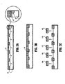
- Figures 1A-1E illustrate a method for forming a multi-chip wafer package, according to an exemplary embodiment of the present invention. More particularly, Figures 1A-1E illustrate a process of forming pockets in a carrier substrate 2 ("cs") and placement of chips within the pockets of the carrier substrate, according to an exemplary embodiment of the present invention,
- a silicon layer 6 for forming pockets at a surface of the carrier substrate 2 is partially bonded at oxide sites 8 of the carrier substrate 2.
- the silicon layer 6 is not bonded to the carrier substrate 2 at non-oxidized areas 3, thereby forming a microscopic void 16 (as depicted in the exploded portion of figure 1A ) in the non-oxidized areas 3 below the silicon layer 6.
- the void 16 includes air or a nitride layer.
- a CVD nitride film may be deposited and patterned so that the void 16 includes a nitride film.
- a microscopic void, a CVD nitride film, or a roughened surface prevents bonding at a surface of a carrier substrate.
- the exploded view shows the carrier substrate 2 including a shallow trench isolation, STI, region 8, the silicon layer 6, a portion of the void 16 formed between the silicon layer 6 and the carrier substrate 2 and adjacent to the STI region 8.
- the void 16 comprises air, a nitride layer, or a roughened silicon surface to prohibit bonding.
- FIGS 1D and 1E illustrate a transfer of chips 11A, 24, 26 and 28 from multiple dummy carriers into their corresponding pockets 12-15 in a carrier substrate 2. It is to be understood that chips 11A, 24, 26, and 28 represent different types of chips, wherein each type of chip is formed on a separate carrier substrate. Further, an insulating layer 20 may be deposited on the carrier substrate 2 to hold multiple chips from different dummy carriers in place, to fill gaps that may be present between a chip and the STI regions 8, and to provide a planarize top surface so that a global interconnect 22 can be formed on the carrier substrate 2 as shown in Figure 1E .
- FIGS 2A-2C illustrate a method of forming chips on a dummy carrier, according to another exemplary embodiment of the present invention.
- a semiconductor layer 6' for forming chips is partially bonded to a dummy carrier 4 at the STI regions 8'.
- the semiconductor layer 6' can be silicon, germanium, gallium arsenide, CdSe, a compound of a group II element and a group IV element, or a compound of a group III and a group V element. In other words, different material may be used to form different chips.
- chip 11A can be assembled into its corresponding pocket (e.g., pocket 14) of the carrier substrate 2.
- dummy carrier 4 or s1
- each dummy carrier could produce a plurality of identical chips 11A-11E.
- the devices 11A-11E shown in Figure 2B have a rectangular shape
- chips 11A-11E may be formed having many different shapes, e.g., square, polygon, u-shaped, v-shaped, etc.
- chips 11A-11E may be formed having a same shape of varying sizes.
- chips 11A-11E may be capacitors having a rectangular shape of varying lengths.
- the semiconductor layer 6' is not bonded to the dummy carrier 4 at non-oxidized areas 3', thereby forming a void 16', as shown in the exploded view of Figure 2A , at the non-oxidized areas 3'.
- the void 16' may include air or a nitride layer. It should be noted that the use of a partial wafer bonding technique provides tighter control over the thickness of the silicon layer 6 and the semiconductor layer 6' in Figures 1A and 2A , respectively.
- the dummy carrier 4 includes a shallow trench isolation, STI, region 8', the semiconductor layer 6', and a region 16' formed between the semiconductor layer 6' and the dummy carrier 4 and adjacent to the STI region 8'.
- the region 16' comprises air, a nitride layer, or a roughened silicon surface to prohibit bonding.
- devices are formed in the semiconductor layer 6' on the dummy carrier 4.
- a conventional metallization process is then carried out on the semiconductor layer 6' in Figure 2B , thereby forming an interconnects layer 10' having about the same thickness as the interconnect layer 10 as shown in Figure 1B .
- the chips 11A-11E of Figure 2C are detached from the dummy carrier 4.
- a partial wafer dicing technique is used to detach the chips 11A-11E from the dummy carrier 4.
- At least one of the chips 11A-11E, e.g., chip 11A, from the dummy carrier 4 is placed in its corresponding pocket, e.g., pocket 14, formed in the carrier substrate 2 of Figure 1C .
- Each dummy carrier may have the same or a different semiconductor top layer 6'. However, within a dummy carrier, identical chips are produced. For example, a first dummy carrier s1 having silicon top layer may be used to produce a plurality of DRAM memory chips. A second dummy carrier s2 having magnetic top layer may be used to produce a plurality of MRAM chips. During assembly, at least one chip from each of the dummy carriers s1-sn may be placed into its corresponding pocket of a carrier substrate cs.
- a MRAM chip from the second dummy carrier s2 and four (4) DRAM chips from the first dummy carrier s1 may be placed in their corresponding pockets of a carrier substrate cs during the assembly of a multi-chip wafer-level package.
- a partial wafer dicing technique enables the cutting and removal of chips from a dummy carrier without breaking the dummy carrier.
- the chips are removed from the dummy carrier by partially cutting through a wafer, preferably just the top semiconductor layer on the dummy carrier. Since this area is not bonded to the dummy carrier, once the wafer is partially cut through, the chips are detached from the dummy carrier.
- the partial wafer dicing technique can only be performed when the wafer is partially bonded to the dummy carrier.
- the advantage of partial-bonding and partial-dicing is, once the chips are detached from their respective dummy carriers, the chips thickness will substantially match the pocket depth of the carrier substrate, thereby avoiding the need for a harsh polishing step.
- Figures 3A-3L illustrate a method for forming both chips and carrier for multi-chip wafer-scale packages according to an exemplary embodiment of the present invention.
- a dielectric layer 301 is deposited on a top surface of a dummy carrier 300. The thickness of the dielectric layer 301 determines the depth of the void to be formed in a subsequent step.
- the dielectric layer 301 is patterned by using a conventional lithographic method with a photoresist mask 303.
- the dielectric layer 301 is etched by a dry etch process to define off-chip areas 304. The off-chip areas 304 will be used as a bonding site in a subsequent step.
- STI regions 305 are formed in the off-chip regions 304.
- the dielectric layer 301 is removed to form a gap region 306.
- a wafer 307 is bonded to the dummy substrate 300 at the STI regions 305, thereby forming a void 302 in the gap region 306.
- the area above the void 302 in the wafer 307 defines a chip area 312, and the area in the wafer 307 above the STI regions 305 defines an inter-chip area 311.
- the wafer 307 is thinned, thereby forming a thinned wafer 308.
- the thickness of the thinned wafer 308 is about 50 to about 100um. This thinning technique and thickness control has been fully established and thus will not be described further.
- devices 310 are formed inside the thinned wafer layer 308.
- interconnects 309 are formed on the thinned wafer layer 308.
- a discrete device may be formed in the inter-chip areas 311 of the thinned wafer layer 308 of the dummy carrier 300.
- the discrete device may include an inductor, a decoupling capacitor, an electrostatic discharge (ESD) diodes, or any other discrete device.
- chips 315A and 315B Prior to cutting out of chips 315A and 315B, these discrete devices reside in the inter-chip areas and may be utilized for testing and monitoring the workings of the chips formed therein. Further, after the formation of the BEOL interconnects 309, the chip areas 312A and 312B are filled with finished devices and interconnects, not shown, to complete the formation of chips 315A and 315B, as shown in Figure 3J .
- a passivation layer 314 is coated on a top surface of the thinned wafer layer 308 to prepare the wafer for dicing. Since the thinned wafer layer 308 is thin, it is possible to use a laser dicing technique or reactive ion etching to cut and detach the chips 315A and 315B from the thinned wafer layer 308 by cutting a channel 319, as shown in Figure 4A , around the chips 315A and 315B. Preferably, the channel width is about 15 um to about 40 um.
- Figure 3K shows a desirable location 320 for dicing through the thinned wafer layer 308 to the void 302, thereby detaching the chips 315A and 315B from the thinned wafer layer 308.
- the devices formed at the inter-chip areas of the dummy carrier, or chip carrier may only be used for testing and monitoring chips formed therein because once the chips are removed from the dummy carrier, the dummy carrier becomes useless and will be discarded.
- the above described process is also used to form pockets in a carrier substrate.
- the steps related to forming chips within the thin wafer are not performed with respect the carrier substrate.
- discrete devices may be formed in the inter-chip areas of the carrier substrate.
- the discrete devices may include an inductor, a decoupling capacitor, an electrostatic discharge (ESD) diodes, or any other discrete devices. That is, when the pockets are cut out, these discrete devices reside in the inter-chip areas so that these discrete devices may be utilized as part of a system after chips have been formed.
- Figure 3L illustrates a structure of a carrier substrate according to an exemplary embodiment of the present invention. More specifically, Figure 3L shows a carrier substrate structure after dummy chips have been removed from the non-bonded areas of the carrier substrate. Now referring to Figure 3L , after the dummy chips, not shown, are cut and detached from the carrier substrate 300', a structure 330 is formed comprising pockets 317A and 317B and prefabricated useful devices 316A, 316B, and 316C in the inter-chip areas 311.
- pockets and chips can be formed on different wafers at different times, and/or from different sources, since the process steps are identical, the thickness of the chips and depth of the pockets are closely tracked.
- a dielectric layer having the same thickness as the dielectric layer 301 of Figure 3A must be deposited to fill the void 302.
- the void 302 is filled with a dielectric layer, an adhesive layer, or a thermal paste prior to dropping the chips into their respective pockets.
- a top surface of all the chips are substantially co-planar with a top surface of the wafer having the pockets, thereby decreasing the number of steps and processes required for forming a multi-chip wafer-level integration package.
- discrete devices formed in inter-chip areas of a dummy carrier are used for testing and monitoring the workings of chips formed thereon.
- discrete devices formed in inter-chip areas of a carrier substrate are an integral part of a multi-chip wafer-level package.
- Figure 4A is a side view of a chip as shown in Figure 3K after a partial wafer dicing technique has been performed.
- predetermined portions of the thinned wafer layer 308 have been removed by using a partial wafer dicing technique, thereby detaching the chip 315A from the carrier substrate 300.
- a buffer region 318 is defined around the chip 315A.
- a dicing technique is performed by dicing through the thinned wafer layer 308 to the void 302, thereby detaching the chip 315A from the substrate. In other words, since the chip 315A is not attached to the substrate at the void 302, the chip 315A is detached once the thinned wafer layer 308 is cut and diced around the chip 315A.
- Figure 4B is a top view of the chip as shown in Figure 3K after a partial wafer dicing technique has been performed.
- chip 315A is show having a buffer region 318 along the outer perimeter of the chip 315A adjacent to the cutting channel 319.
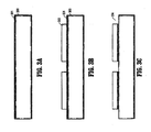
- Figures 5A - 5C illustrate a method for detaching a chip formed on carrier substrate according to an exemplary embodiment of the present invention.
- a thin wafer layer 510 having a thickness d1 is bonded to a thicker substrate 530 having a thickness of d2 to sustain the mechanical strength during handling and processing.
- the thickness of d1 is about 50 um to about 300 um.
- the bonded area 521 is formed by the wafer layer 510 bonding to the patterned oxide layer 540.
- the unbonded area 522 results from the lack of an oxide layer.
- a chip 520, or die, is formed in the thin wafer layer 510 within the unbonded area.
- the wafer layer 510 may be silicon, germanium, gallium arsenide, CdSe, a compound of a Group II element and a Group VI element, or a compound of a Group III element and a Group IV element.
- a partial wafer dicing technique may be performed by forming a photoresist mask 500 on top of the thin wafer layer 510 and exposing the photoresist mask 500 by lithography. After the photomask 500 is defined, a dry or wet etching process is carried out to etch the thin wafer layer 510. Alternatively, the partial dicing can also be done using maskless direct laser cutting to detach the chip 520.
- Figure 5B shows trenches 550, which are formed by etching through the thin wafer layer 510 to the unbonded area 522 surrounding the chip 520.
- the chip 520, or die is removed from the unbonded area 522, thereby forming a pocket 560.
- a High-density plasma, or reactive ion etch can be used to etch trench 550 and cut the chip or die effectively.
- a pocket can be formed by removing a dummy chip from the substrate. The depth of the pocket should have substantially the same thickness as the real chip, so that after the chip is mounted, a top surface of the chip will be substantially co-planar with a top surface of the wafer.
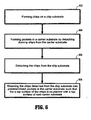
- FIG. 6 is a flowchart illustrating a method for forming a multi-chip wafer-level package, according to an exemplary embodiment of the present invention.
- a plurality of chips is formed on a chip substrate (step 602).
- pockets are formed in a carrier substrate by detaching dummy chips from the carrier substrate (step 604).
- the chips are detached from the chip substrate (step 606). It is to be understood that steps 604 and 606 may be performed simultaneously or in a different order.
- the chips detached from the chip substrate are then mounted into predetermined pockets in the carrier substrate such that a top surface of the chips is substantially co-planar with a top surface of the carrier substrate (step 608).
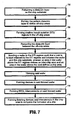
- Figure 7 is a flowchart illustrating a method for forming a plurality of chips on a chip substrate, according to an exemplary embodiment of the present invention.
- Figure 7 illustrates an exemplary method of step 602 in Fig. 6 , which relates to forming chips on a chip substrate.
- a dielectric layer on a chip substrate is patterned (step 702).
- the pattern dielectric layer is etched to define off-chip areas (step 704). Shallow trench isolation (STI) regions are formed in the off-chip areas (step 706).
- the dielectric layer between the off-chip areas is removed (step 708).
- STI Shallow trench isolation
- a wafer is bonded to the STI regions such that a void is formed adjacent to the STI regions and between the wafer and chip substrate, wherein an area in the wafer above the STI regions defines an inter-chip area and an area above the void defines a chip area (step 710).
- the wafer is thinned (step 712).
- Devices are then formed in the thinned wafer (step 714).
- BEOL interconnects are formed on the thinned wafer having devices formed therein (step 716).
- finishing devices and interconnects are formed in the chip area of the thinned wafer to complete the formation of a chip (step 718). Further, it is to be understood that the process described above may be employed to form many different types of chips on different chip substrates.
- Figure 8 is a flowchart illustrating a method for forming a plurality of pockets in a carrier substrate, according to an exemplary embodiment of the present invention.
- Figure 8 illustrates an exemplary method of step 604 in Fig. 6 , which relates to forming pockets in a carrier substrate.
- a dielectric layer on the carrier substrate is patterned (step 802).
- the pattern dielectric layer is etched to define off-chip areas (step 804).
- shallow trench isolation (STI) regions are formed in the off-chip areas (step 806).
- the dielectric layer is then removed between the off-chip areas (step 808).
- STI shallow trench isolation
- a wafer is bonded to the STI regions such that a void is formed adjacent to the STI regions and between the wafer and the carrier substrate, wherein an area in the wafer above the STI regions defines an inter-chip area and an area above the void defines a chip area (step 810).
- the wafer is thinned (step 812).
- BEOL interconnects are formed on the thinned wafer (step 814).
- a top surface of said thinned wafer is coated with a passivation layer (step 816).
- a channel is diced in the chip areas of the wafer such that a predetermined portion, or dummy chip, of the wafer is detach, thereby forming pockets within the wafer (step 818).
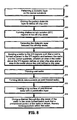
- Figure 9 is a flowchart illustrating a method for detaching a chip from the chip substrate, according to an exemplary embodiment of the present invention.
- Figure 9 illustrates an exemplary method of step 606 in Fig. 6 , which relates to detaching the chips from the chip substrate.
- a top surface of said thinned wafer is coated with a passivation layer to protect the chip (step 902).
- a channel is diced through the chip areas of the wafer to the void, thereby detaching the chip from the chip substrate (step 904).
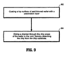
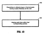
- FIG 10 is a flowchart illustrating a method for mounting a chip detached from the chip substrate into a predetermined pocket in a carrier substrate, according to an exemplary embodiment of the present invention.
- Fig. 10 illustrates an exemplary method of step 608 in Fig. 6 .
- an adhesive layer or thermal paste having a same thickness as the void is deposited in a bottom portion of the pocket (step 1002).
- the chips are placed and aligned within their corresponding pockets (step 1004).
- a dielectric layer having the same dimensions as the void may be used in lieu of the adhesive layer or thermal paste.
- exemplary embodiments of the present invention provide efficient methods for forming a co-planar multi-chip wafer-level package where partial wafer bonding and partial wafer dicing techniques are used to create chips as well as pockets at a surface of a wafer.
- the finished chips are mounted in the corresponding pockets of a wafer, and global interconnects among the chips are formed on the top planar surface of bonded chips.
- These methods facilitate the integration of chips fabricated with different process steps and materials. There is no need to use a harsh planarization process such as chemical-mechanical polish to planarize the top surfaces of the chips. Since the chips are precisely aligned to each other and all the chips are mounted facing up, the module is ready for global wiring, which eliminates the need to flip the chips from an upside-down position.
Landscapes
- Engineering & Computer Science (AREA)
- Physics & Mathematics (AREA)
- Condensed Matter Physics & Semiconductors (AREA)
- General Physics & Mathematics (AREA)
- Computer Hardware Design (AREA)
- Microelectronics & Electronic Packaging (AREA)
- Power Engineering (AREA)
- Manufacturing & Machinery (AREA)
- Semiconductor Integrated Circuits (AREA)
- Dicing (AREA)
- Wire Bonding (AREA)
- Crystals, And After-Treatments Of Crystals (AREA)
Claims (11)
- Verfahren zur Herstellung von Chipgehäusen in Wafergröße für mehrere Chips, wobei das Verfahren das Folgende umfasst:Herstellen mehrerer verschiedenartiger Chips (11A, 24, 26, 28) auf mehreren Chipsubstraten, wobei jedes der mehreren Chipsubstrate verwendet wird, um nur eine Art von Chip herzustellen;Lösen der mehreren verschiedenartigen Chips von den mehreren Chipsubstraten;Bilden von Taschen (12, 13, 14, 15) in einem Trägersubstrat (2), wobei jede der Taschen einen der verschiedenartigen Chips aufnimmt;Anbringen der mehreren Chips in ihren entsprechenden Taschen in dem Trägersubstrat, derart, dass eine obere Fläche der mehreren Chips im Wesentlichen koplanar mit einer oberen Fläche des Trägersubstrats ist;dadurch gekennzeichnet, dass der Schritt des Bildens von Taschen in dem Trägersubstrat den folgenden Schritt umfasst:Bonden eines Wafers (6) an STI-Regionen (8) in dem Trägersubstrat, derart, dass in Nachbarschaft zu den STI-Regionen und zwischen dem Wafer und dem Trägersubstrat Lücken gebildet werden, wobei Bereiche in dem Wafer, die sich über den STI-Regionen befinden, Bereiche zwischen Chips definieren und Bereiche in dem Wafer, die sich über den Lücken befinden, Chipbereiche definieren.
- Verfahren nach Anspruch 1, wobei der Schritt des Herstellens mehrerer der Chips auf mehreren Chipsubstraten den folgenden Schritt umfasst:Bonden eines Wafers an Regionen flacher Grabenisolierungen (STI, Shallow Trench Isolations) in jedem der Chipsubstrate, derart, dass in Nachbarschaft zu den STI-Regionen und zwischen dem Wafer und einem Chipsubstrat Lücken gebildet werden, wobei Bereiche in dem Wafer, die sich über den STI-Regionen befinden, Bereiche zwischen Chips definieren und Bereiche in dem Wafer, die sich über den Lücken befinden, Chipbereiche definieren.
- Verfahren nach Anspruch 2, welches vor dem Bonden des Wafers an die STI-Regionen ferner die folgenden Schritte umfasst:Strukturieren einer dielektrischen Schicht auf dem Chipsubstrat;Ätzen der strukturierten dielektrischen Schicht, um Bereiche außerhalb der Chips zu definieren;Bilden von STI-Regionen in den Bereichen außerhalb der Chips; undEntfernen der dielektrischen Schicht zwischen den Bereichen außerhalb der Chips.
- Verfahren nach Anspruch 2, welches ferner das Folgende umfasst:Dünner machen des Wafers;Bilden von Einheiten in dem dünner gemachten Wafer;Bilden von BEOL-Verbindungen auf dem dünner gemachten Wafer; undBilden von abschließenden Einheiten und Zwischenverbindungen in den Chipbereichen, um die Herstellung der mehreren Chips zu vollenden.
- Verfahren nach Anspruch 4, wobei der Schritt des Lösens der mehreren Chips von den mehreren Chipsubstraten die folgenden Schritte umfasst:Beschichten einer oberen Fläche des dünner gemachten Wafers mit einer Passivierungsschicht; undSchneiden eines Kanals durch die Chipbereiche des dünner gemachten Wafers zu den Lücken, wodurch die mehreren Chips von den mehreren Chipsubstraten gelöst werden.
- Verfahren nach Anspruch 1, welches vor dem Bonden eines Wafers an die STI-Regionen ferner die folgenden Schritte umfasst:Strukturieren einer dielektrischen Schicht auf dem Chipträger;Ätzen der strukturierten dielektrischen Schicht, um Bereiche außerhalb der Chips zu definieren;Bilden von Regionen flacher Grabenisolierungen (STI-Regionen) in den Bereichen außerhalb der Chips; undEntfernen der dielektrischen Schicht zwischen den Bereichen außerhalb der Chips.
- Verfahren nach Anspruch 1, welches ferner das Folgende umfasst:Dünner machen des Wafers;Bilden von BEOL(Back-End-Of-Line)-Verbindungen auf dem dünner gemachten Wafer;Beschichten einer oberen Fläche des dünner gemachten Wafers mit einer Passivierungsschicht; undSchneiden eines Kanals in den Chipbereichen des dünner gemachten Wafers, derart, dass ein vorgegebener Abschnitt des dünner gemachten Wafers gelöst wird, wodurch Taschen innerhalb des dünner gemachten Wafers gebildet werden.
- Verfahren nach einem der Ansprüche 2 bis 7, welches ferner das Bilden einer diskreten Einheit in den Bereichen zwischen den Chips des Chipsubstrats umfasst.
- Verfahren nach Anspruch 1, wobei der Schritt des Anbringens der mehreren Chips in ihren entsprechenden Taschen die folgenden Schritte umfasst:Aufbringen einer dielektrischen Schicht in den Chipbereichen, welche im Wesentlichen dieselbe Dicke wie die Lücken aufweist; undAusrichten der mehreren Chips in ihren entsprechenden Taschen.
- Verfahren nach Anspruch 1, wobei der Schritt des Anbringens der mehreren Chips in ihren entsprechenden Taschen die folgenden Schritte umfasst:Aufbringen einer Haftschicht oder einer Wärmeleitpaste in den Chipbereichen, welche im Wesentlichen dieselbe Dicke wie die Lücken aufweist; undAusrichten der mehreren Chips in ihren entsprechenden Taschen.
- Verfahren nach einem der vorhergehenden Ansprüche, welches ferner den folgenden Schritt umfasst: Anwenden des partiellen Wafer-Bondings für die Schritte des Herstellens mehrerer verschiedenartiger Chips und des Bildens der Taschen und Anwenden des partiellen Wafer-Schneidens für die Schritte des Lösens der mehreren verschiedenartigen Chips von dem Chipsubstrat und des Bildens der Taschen.
Applications Claiming Priority (2)
| Application Number | Priority Date | Filing Date | Title |
|---|---|---|---|
| US10/994,494 US7405108B2 (en) | 2004-11-20 | 2004-11-20 | Methods for forming co-planar wafer-scale chip packages |
| PCT/EP2005/056009 WO2006053879A1 (en) | 2004-11-20 | 2005-11-16 | Methods for forming co-planar wafer-scale chip packages |
Publications (2)
| Publication Number | Publication Date |
|---|---|
| EP1817793A1 EP1817793A1 (de) | 2007-08-15 |
| EP1817793B1 true EP1817793B1 (de) | 2010-08-11 |
Family
ID=35735294
Family Applications (1)
| Application Number | Title | Priority Date | Filing Date |
|---|---|---|---|
| EP05808156A Not-in-force EP1817793B1 (de) | 2004-11-20 | 2005-11-16 | Verfahren zur herstellung von koplanaren chipgehäusen in wafergrösse |
Country Status (9)
| Country | Link |
|---|---|
| US (2) | US7405108B2 (de) |
| EP (1) | EP1817793B1 (de) |
| JP (2) | JP5459959B2 (de) |
| KR (1) | KR100992015B1 (de) |
| CN (1) | CN100437952C (de) |
| AT (1) | ATE477588T1 (de) |
| DE (1) | DE602005022919D1 (de) |
| TW (1) | TWI362706B (de) |
| WO (1) | WO2006053879A1 (de) |
Families Citing this family (26)
| Publication number | Priority date | Publication date | Assignee | Title |
|---|---|---|---|---|
| US7405108B2 (en) * | 2004-11-20 | 2008-07-29 | International Business Machines Corporation | Methods for forming co-planar wafer-scale chip packages |
| US7442579B2 (en) * | 2004-11-22 | 2008-10-28 | International Business Machines Corporation | Methods to achieve precision alignment for wafer scale packages |
| DE102005039479B3 (de) * | 2005-08-18 | 2007-03-29 | Infineon Technologies Ag | Halbleiterbauteil mit gedünntem Halbleiterchip und Verfahren zur Herstellung des gedünnten Halbleiterbauteils |
| US7658901B2 (en) * | 2005-10-14 | 2010-02-09 | The Trustees Of Princeton University | Thermally exfoliated graphite oxide |
| JP4559993B2 (ja) * | 2006-03-29 | 2010-10-13 | 株式会社東芝 | 半導体装置の製造方法 |
| KR100829392B1 (ko) * | 2006-08-24 | 2008-05-13 | 동부일렉트로닉스 주식회사 | SoC 및 그 제조 방법 |
| TW200941661A (en) * | 2008-03-19 | 2009-10-01 | Integrated Circuit Solution Inc | Shape of window formed in a substrate for window ball grid array package |
| JP4828559B2 (ja) * | 2008-03-24 | 2011-11-30 | 新光電気工業株式会社 | 配線基板の製造方法及び電子装置の製造方法 |
| US8772087B2 (en) * | 2009-10-22 | 2014-07-08 | Infineon Technologies Ag | Method and apparatus for semiconductor device fabrication using a reconstituted wafer |
| US8322022B1 (en) | 2010-06-28 | 2012-12-04 | Western Digital (Fremont), Llc | Method for providing an energy assisted magnetic recording head in a wafer packaging configuration |
| CN102386088B (zh) * | 2010-09-03 | 2014-06-25 | 中芯国际集成电路制造(上海)有限公司 | 用于去除半导体器件结构上的光致抗蚀剂层的方法 |
| CN102769002B (zh) * | 2011-04-30 | 2016-09-14 | 中国科学院微电子研究所 | 半导体器件及其形成方法、封装结构 |
| JP6063641B2 (ja) * | 2012-05-16 | 2017-01-18 | 株式会社ディスコ | ウエーハ保護部材 |
| US20150380369A1 (en) * | 2013-09-30 | 2015-12-31 | Nantong Fujitsu Microelectronics Co., Ltd | Wafer packaging structure and packaging method |
| US9123546B2 (en) | 2013-11-14 | 2015-09-01 | Taiwan Semiconductor Manufacturing Company Limited | Multi-layer semiconductor device structures with different channel materials |
| US9350339B2 (en) * | 2014-07-18 | 2016-05-24 | Qualcomm Incorporated | Systems and methods for clock distribution in a die-to-die interface |
| EP3467567B1 (de) | 2016-05-27 | 2024-02-07 | Hamamatsu Photonics K.K. | Herstellungsverfahren für fabry-perot-interferenzfilter |
| JP6341959B2 (ja) | 2016-05-27 | 2018-06-13 | 浜松ホトニクス株式会社 | ファブリペロー干渉フィルタの製造方法 |
| FI3505987T3 (fi) | 2016-08-24 | 2023-12-19 | Hamamatsu Photonics Kk | Fabry-perot-häiriösuodatin |
| US10916507B2 (en) | 2018-12-04 | 2021-02-09 | International Business Machines Corporation | Multiple chip carrier for bridge assembly |
| GB2582382B (en) * | 2019-03-22 | 2023-10-25 | Cirrus Logic Int Semiconductor Ltd | Semiconductor structures |
| US11456247B2 (en) * | 2019-06-13 | 2022-09-27 | Nanya Technology Corporation | Semiconductor device and fabrication method for the same |
| CN110690868B (zh) * | 2019-09-27 | 2021-02-19 | 无锡市好达电子股份有限公司 | 一种滤波器的新型晶圆级封装方法 |
| CN111128716B (zh) * | 2019-11-15 | 2023-10-17 | 西安电子科技大学 | 一种大面积图形自对准的异质集成方法 |
| KR20210120221A (ko) | 2020-03-26 | 2021-10-07 | 삼성전자주식회사 | 반도체 스택 및 그 제조 방법 |
| TWI790003B (zh) * | 2021-11-18 | 2023-01-11 | 佳邦科技股份有限公司 | 過電壓保護元件 |
Family Cites Families (21)
| Publication number | Priority date | Publication date | Assignee | Title |
|---|---|---|---|---|
| JPS6281745A (ja) * | 1985-10-05 | 1987-04-15 | Fujitsu Ltd | ウエハ−規模のlsi半導体装置とその製造方法 |
| US4866501A (en) * | 1985-12-16 | 1989-09-12 | American Telephone And Telegraph Company At&T Bell Laboratories | Wafer scale integration |
| US5091331A (en) * | 1990-04-16 | 1992-02-25 | Harris Corporation | Ultra-thin circuit fabrication by controlled wafer debonding |
| JPH0645436A (ja) * | 1992-07-22 | 1994-02-18 | Nec Corp | 半導体基板の貼付方法 |
| US5324687A (en) * | 1992-10-16 | 1994-06-28 | General Electric Company | Method for thinning of integrated circuit chips for lightweight packaged electronic systems |
| JPH0878487A (ja) * | 1994-08-31 | 1996-03-22 | Nec Kyushu Ltd | 半導体基板および半導体装置の製造方法 |
| US5770884A (en) * | 1995-06-30 | 1998-06-23 | International Business Machines Corporation | Very dense integrated circuit package |
| US5880007A (en) * | 1997-09-30 | 1999-03-09 | Siemens Aktiengesellschaft | Planarization of a non-conformal device layer in semiconductor fabrication |
| US6177299B1 (en) * | 1998-01-15 | 2001-01-23 | International Business Machines Corporation | Transistor having substantially isolated body and method of making the same |
| JPH11354667A (ja) * | 1998-06-05 | 1999-12-24 | Nippon Telegr & Teleph Corp <Ntt> | 電子部品およびその実装方法 |
| US6627477B1 (en) * | 2000-09-07 | 2003-09-30 | International Business Machines Corporation | Method of assembling a plurality of semiconductor devices having different thickness |
| US6555906B2 (en) * | 2000-12-15 | 2003-04-29 | Intel Corporation | Microelectronic package having a bumpless laminated interconnection layer |
| FR2823596B1 (fr) * | 2001-04-13 | 2004-08-20 | Commissariat Energie Atomique | Substrat ou structure demontable et procede de realisation |
| JP2003197850A (ja) * | 2001-12-26 | 2003-07-11 | Sony Corp | 半導体装置及びその製造方法 |
| JP4260405B2 (ja) * | 2002-02-08 | 2009-04-30 | 株式会社ルネサステクノロジ | 半導体集積回路装置の製造方法 |
| US7203393B2 (en) * | 2002-03-08 | 2007-04-10 | Movaz Networks, Inc. | MEMS micro mirrors driven by electrodes fabricated on another substrate |
| WO2003100829A2 (en) * | 2002-05-20 | 2003-12-04 | Imagerlabs | Forming a multi segment integrated circuit with isolated substrates |
| US6964881B2 (en) * | 2002-08-27 | 2005-11-15 | Micron Technology, Inc. | Multi-chip wafer level system packages and methods of forming same |
| US7078320B2 (en) * | 2004-08-10 | 2006-07-18 | International Business Machines Corporation | Partial wafer bonding and dicing |
| US7005319B1 (en) * | 2004-11-19 | 2006-02-28 | International Business Machines Corporation | Global planarization of wafer scale package with precision die thickness control |
| US7405108B2 (en) * | 2004-11-20 | 2008-07-29 | International Business Machines Corporation | Methods for forming co-planar wafer-scale chip packages |
-
2004
- 2004-11-20 US US10/994,494 patent/US7405108B2/en active Active
-
2005
- 2005-11-16 JP JP2007541952A patent/JP5459959B2/ja not_active Expired - Fee Related
- 2005-11-16 DE DE602005022919T patent/DE602005022919D1/de active Active
- 2005-11-16 AT AT05808156T patent/ATE477588T1/de not_active IP Right Cessation
- 2005-11-16 EP EP05808156A patent/EP1817793B1/de not_active Not-in-force
- 2005-11-16 KR KR1020077011373A patent/KR100992015B1/ko not_active IP Right Cessation
- 2005-11-16 CN CNB2005800325958A patent/CN100437952C/zh active Active
- 2005-11-16 WO PCT/EP2005/056009 patent/WO2006053879A1/en active Application Filing
- 2005-11-17 TW TW094140468A patent/TWI362706B/zh not_active IP Right Cessation
-
2008
- 2008-05-15 US US12/121,468 patent/US7867820B2/en not_active Expired - Fee Related
-
2011
- 2011-07-22 JP JP2011160519A patent/JP5474002B2/ja not_active Expired - Fee Related
Also Published As
| Publication number | Publication date |
|---|---|
| JP5459959B2 (ja) | 2014-04-02 |
| US20060110851A1 (en) | 2006-05-25 |
| CN101027765A (zh) | 2007-08-29 |
| TWI362706B (en) | 2012-04-21 |
| JP2008521228A (ja) | 2008-06-19 |
| CN100437952C (zh) | 2008-11-26 |
| EP1817793A1 (de) | 2007-08-15 |
| US7867820B2 (en) | 2011-01-11 |
| KR20070085402A (ko) | 2007-08-27 |
| DE602005022919D1 (de) | 2010-09-23 |
| US20080280399A1 (en) | 2008-11-13 |
| WO2006053879A1 (en) | 2006-05-26 |
| KR100992015B1 (ko) | 2010-11-05 |
| JP2011249830A (ja) | 2011-12-08 |
| JP5474002B2 (ja) | 2014-04-16 |
| US7405108B2 (en) | 2008-07-29 |
| TW200633081A (en) | 2006-09-16 |
| ATE477588T1 (de) | 2010-08-15 |
Similar Documents
| Publication | Publication Date | Title |
|---|---|---|
| EP1817793B1 (de) | Verfahren zur herstellung von koplanaren chipgehäusen in wafergrösse | |
| TWI478282B (zh) | 半導體元件的形成方法 | |
| US20220181211A1 (en) | Composite Wafer, Semiconductor Device and Electronic Component | |
| US7566634B2 (en) | Method for chip singulation | |
| JP2008521228A5 (de) | ||
| US11476162B2 (en) | Method for dicing a semiconductor substrate into a plurality of dies | |
| EP3171399B1 (de) | Verfahren zur vereinzelung eines stapels von halbleiterwafern | |
| US20140203409A1 (en) | Integrated Circuit Structures, Semiconductor Structures, And Semiconductor Die | |
| US20240006223A1 (en) | Method for semiconductor die edge protection and semiconductor die separation | |
| US20150371956A1 (en) | Crackstops for bulk semiconductor wafers | |
| US20210111102A1 (en) | Self-aligned contact openings for backside through substrate vias | |
| US10256147B2 (en) | Dicing method | |
| US20240006320A1 (en) | Semiconductor die edge protection for semiconductor device assemblies and associated systems and methods | |
| US10818570B1 (en) | Stacked semiconductor devices having dissimilar-sized dies | |
| US8841742B2 (en) | Low temperature layer transfer process using donor structure with material in recesses in transfer layer, semiconductor structures fabricated using such methods | |
| CN112151439A (zh) | 晶圆及其制作方法、半导体器件 | |
| US20240332130A1 (en) | High density vertical interconnect | |
| US20240038686A1 (en) | Semiconductor packages and methods of manufacturing thereof | |
| EP1670055A1 (de) | Verfahren zur Trennung von Chips | |
| EP1641038B1 (de) | Verfahren zur Trennung von Chips |
Legal Events
| Date | Code | Title | Description |
|---|---|---|---|
| PUAI | Public reference made under article 153(3) epc to a published international application that has entered the european phase |
Free format text: ORIGINAL CODE: 0009012 |
|
| 17P | Request for examination filed |
Effective date: 20070604 |
|
| AK | Designated contracting states |
Kind code of ref document: A1 Designated state(s): AT BE BG CH CY CZ DE DK EE ES FI FR GB GR HU IE IS IT LI LT LU LV MC NL PL PT RO SE SI SK TR |
|
| RIN1 | Information on inventor provided before grant (corrected) |
Inventor name: BURRELL, LLOYD Inventor name: SAUTER, WOLFGANGC Inventor name: CHEN, HOWARD, HAO Inventor name: HSU, LOUIS |
|
| DAX | Request for extension of the european patent (deleted) | ||
| 17Q | First examination report despatched |
Effective date: 20091216 |
|
| GRAP | Despatch of communication of intention to grant a patent |
Free format text: ORIGINAL CODE: EPIDOSNIGR1 |
|
| RIC1 | Information provided on ipc code assigned before grant |
Ipc: H01L 21/48 20060101AFI20100423BHEP Ipc: H01L 23/538 20060101ALI20100423BHEP Ipc: H01L 23/14 20060101ALI20100423BHEP |
|
| GRAS | Grant fee paid |
Free format text: ORIGINAL CODE: EPIDOSNIGR3 |
|
| GRAA | (expected) grant |
Free format text: ORIGINAL CODE: 0009210 |
|
| AK | Designated contracting states |
Kind code of ref document: B1 Designated state(s): AT BE BG CH CY CZ DE DK EE ES FI FR GB GR HU IE IS IT LI LT LU LV MC NL PL PT RO SE SI SK TR |
|
| REG | Reference to a national code |
Ref country code: GB Ref legal event code: FG4D |
|
| REG | Reference to a national code |
Ref country code: CH Ref legal event code: EP Ref country code: CH Ref legal event code: NV Representative=s name: IBM RESEARCH GMBH ZURICH RESEARCH LABORATORY INTEL |
|
| REG | Reference to a national code |
Ref country code: IE Ref legal event code: FG4D |
|
| REF | Corresponds to: |
Ref document number: 602005022919 Country of ref document: DE Date of ref document: 20100923 Kind code of ref document: P |
|
| REG | Reference to a national code |
Ref country code: GB Ref legal event code: 746 Effective date: 20100906 |
|
| REG | Reference to a national code |
Ref country code: NL Ref legal event code: VDEP Effective date: 20100811 |
|
| LTIE | Lt: invalidation of european patent or patent extension |
Effective date: 20100811 |
|
| PG25 | Lapsed in a contracting state [announced via postgrant information from national office to epo] |
Ref country code: NL Free format text: LAPSE BECAUSE OF FAILURE TO SUBMIT A TRANSLATION OF THE DESCRIPTION OR TO PAY THE FEE WITHIN THE PRESCRIBED TIME-LIMIT Effective date: 20100811 Ref country code: LT Free format text: LAPSE BECAUSE OF FAILURE TO SUBMIT A TRANSLATION OF THE DESCRIPTION OR TO PAY THE FEE WITHIN THE PRESCRIBED TIME-LIMIT Effective date: 20100811 Ref country code: FI Free format text: LAPSE BECAUSE OF FAILURE TO SUBMIT A TRANSLATION OF THE DESCRIPTION OR TO PAY THE FEE WITHIN THE PRESCRIBED TIME-LIMIT Effective date: 20100811 Ref country code: AT Free format text: LAPSE BECAUSE OF FAILURE TO SUBMIT A TRANSLATION OF THE DESCRIPTION OR TO PAY THE FEE WITHIN THE PRESCRIBED TIME-LIMIT Effective date: 20100811 |
|
| PG25 | Lapsed in a contracting state [announced via postgrant information from national office to epo] |
Ref country code: BG Free format text: LAPSE BECAUSE OF FAILURE TO SUBMIT A TRANSLATION OF THE DESCRIPTION OR TO PAY THE FEE WITHIN THE PRESCRIBED TIME-LIMIT Effective date: 20101111 Ref country code: PL Free format text: LAPSE BECAUSE OF FAILURE TO SUBMIT A TRANSLATION OF THE DESCRIPTION OR TO PAY THE FEE WITHIN THE PRESCRIBED TIME-LIMIT Effective date: 20100811 Ref country code: CY Free format text: LAPSE BECAUSE OF FAILURE TO SUBMIT A TRANSLATION OF THE DESCRIPTION OR TO PAY THE FEE WITHIN THE PRESCRIBED TIME-LIMIT Effective date: 20100811 Ref country code: PT Free format text: LAPSE BECAUSE OF FAILURE TO SUBMIT A TRANSLATION OF THE DESCRIPTION OR TO PAY THE FEE WITHIN THE PRESCRIBED TIME-LIMIT Effective date: 20101213 Ref country code: SI Free format text: LAPSE BECAUSE OF FAILURE TO SUBMIT A TRANSLATION OF THE DESCRIPTION OR TO PAY THE FEE WITHIN THE PRESCRIBED TIME-LIMIT Effective date: 20100811 Ref country code: IS Free format text: LAPSE BECAUSE OF FAILURE TO SUBMIT A TRANSLATION OF THE DESCRIPTION OR TO PAY THE FEE WITHIN THE PRESCRIBED TIME-LIMIT Effective date: 20101211 |
|
| PG25 | Lapsed in a contracting state [announced via postgrant information from national office to epo] |
Ref country code: GR Free format text: LAPSE BECAUSE OF FAILURE TO SUBMIT A TRANSLATION OF THE DESCRIPTION OR TO PAY THE FEE WITHIN THE PRESCRIBED TIME-LIMIT Effective date: 20101112 Ref country code: BE Free format text: LAPSE BECAUSE OF FAILURE TO SUBMIT A TRANSLATION OF THE DESCRIPTION OR TO PAY THE FEE WITHIN THE PRESCRIBED TIME-LIMIT Effective date: 20100811 Ref country code: LV Free format text: LAPSE BECAUSE OF FAILURE TO SUBMIT A TRANSLATION OF THE DESCRIPTION OR TO PAY THE FEE WITHIN THE PRESCRIBED TIME-LIMIT Effective date: 20100811 Ref country code: SE Free format text: LAPSE BECAUSE OF FAILURE TO SUBMIT A TRANSLATION OF THE DESCRIPTION OR TO PAY THE FEE WITHIN THE PRESCRIBED TIME-LIMIT Effective date: 20100811 |
|
| PG25 | Lapsed in a contracting state [announced via postgrant information from national office to epo] |
Ref country code: DK Free format text: LAPSE BECAUSE OF FAILURE TO SUBMIT A TRANSLATION OF THE DESCRIPTION OR TO PAY THE FEE WITHIN THE PRESCRIBED TIME-LIMIT Effective date: 20100811 |
|
| PG25 | Lapsed in a contracting state [announced via postgrant information from national office to epo] |
Ref country code: EE Free format text: LAPSE BECAUSE OF FAILURE TO SUBMIT A TRANSLATION OF THE DESCRIPTION OR TO PAY THE FEE WITHIN THE PRESCRIBED TIME-LIMIT Effective date: 20100811 Ref country code: CZ Free format text: LAPSE BECAUSE OF FAILURE TO SUBMIT A TRANSLATION OF THE DESCRIPTION OR TO PAY THE FEE WITHIN THE PRESCRIBED TIME-LIMIT Effective date: 20100811 Ref country code: IT Free format text: LAPSE BECAUSE OF FAILURE TO SUBMIT A TRANSLATION OF THE DESCRIPTION OR TO PAY THE FEE WITHIN THE PRESCRIBED TIME-LIMIT Effective date: 20100811 Ref country code: SK Free format text: LAPSE BECAUSE OF FAILURE TO SUBMIT A TRANSLATION OF THE DESCRIPTION OR TO PAY THE FEE WITHIN THE PRESCRIBED TIME-LIMIT Effective date: 20100811 Ref country code: RO Free format text: LAPSE BECAUSE OF FAILURE TO SUBMIT A TRANSLATION OF THE DESCRIPTION OR TO PAY THE FEE WITHIN THE PRESCRIBED TIME-LIMIT Effective date: 20100811 |
|
| PLBE | No opposition filed within time limit |
Free format text: ORIGINAL CODE: 0009261 |
|
| STAA | Information on the status of an ep patent application or granted ep patent |
Free format text: STATUS: NO OPPOSITION FILED WITHIN TIME LIMIT |
|
| PG25 | Lapsed in a contracting state [announced via postgrant information from national office to epo] |
Ref country code: ES Free format text: LAPSE BECAUSE OF FAILURE TO SUBMIT A TRANSLATION OF THE DESCRIPTION OR TO PAY THE FEE WITHIN THE PRESCRIBED TIME-LIMIT Effective date: 20101122 Ref country code: MC Free format text: LAPSE BECAUSE OF NON-PAYMENT OF DUE FEES Effective date: 20101130 |
|
| REG | Reference to a national code |
Ref country code: CH Ref legal event code: PL |
|
| 26N | No opposition filed |
Effective date: 20110512 |
|
| PG25 | Lapsed in a contracting state [announced via postgrant information from national office to epo] |
Ref country code: LI Free format text: LAPSE BECAUSE OF NON-PAYMENT OF DUE FEES Effective date: 20101130 Ref country code: CH Free format text: LAPSE BECAUSE OF NON-PAYMENT OF DUE FEES Effective date: 20101130 |
|
| REG | Reference to a national code |
Ref country code: DE Ref legal event code: R097 Ref document number: 602005022919 Country of ref document: DE Effective date: 20110512 |
|
| PG25 | Lapsed in a contracting state [announced via postgrant information from national office to epo] |
Ref country code: IE Free format text: LAPSE BECAUSE OF NON-PAYMENT OF DUE FEES Effective date: 20101116 |
|
| PG25 | Lapsed in a contracting state [announced via postgrant information from national office to epo] |
Ref country code: LU Free format text: LAPSE BECAUSE OF NON-PAYMENT OF DUE FEES Effective date: 20101116 Ref country code: HU Free format text: LAPSE BECAUSE OF FAILURE TO SUBMIT A TRANSLATION OF THE DESCRIPTION OR TO PAY THE FEE WITHIN THE PRESCRIBED TIME-LIMIT Effective date: 20110212 |
|
| PG25 | Lapsed in a contracting state [announced via postgrant information from national office to epo] |
Ref country code: TR Free format text: LAPSE BECAUSE OF FAILURE TO SUBMIT A TRANSLATION OF THE DESCRIPTION OR TO PAY THE FEE WITHIN THE PRESCRIBED TIME-LIMIT Effective date: 20100811 |
|
| REG | Reference to a national code |
Ref country code: FR Ref legal event code: PLFP Year of fee payment: 11 |
|
| PGFP | Annual fee paid to national office [announced via postgrant information from national office to epo] |
Ref country code: GB Payment date: 20151111 Year of fee payment: 11 |
|
| PGFP | Annual fee paid to national office [announced via postgrant information from national office to epo] |
Ref country code: FR Payment date: 20151008 Year of fee payment: 11 |
|
| REG | Reference to a national code |
Ref country code: DE Ref legal event code: R081 Ref document number: 602005022919 Country of ref document: DE Owner name: GLOBALFOUNDRIES INC., KY Free format text: FORMER OWNER: INTERNATIONAL BUSINESS MACHINES CORPORATION, ARMONK, NY, US Ref country code: DE Ref legal event code: R082 Ref document number: 602005022919 Country of ref document: DE Representative=s name: RICHARDT PATENTANWAELTE PARTG MBB, DE Ref country code: DE Ref legal event code: R081 Ref document number: 602005022919 Country of ref document: DE Owner name: GLOBALFOUNDRIES INC., KY Free format text: FORMER OWNER: INTERNATIONAL BUSINESS MACHINES CORPORATION, ARMONK, N.Y., US |
|
| REG | Reference to a national code |
Ref country code: DE Ref legal event code: R081 Ref document number: 602005022919 Country of ref document: DE Owner name: GLOBALFOUNDRIES INC., KY Free format text: FORMER OWNER: GLOBALFOUNDRIES US 2 LLC (N.D.GES.DES STAATES DELAWARE), HOPEWELL JUNCTION, N.Y., US Ref country code: DE Ref legal event code: R082 Ref document number: 602005022919 Country of ref document: DE Representative=s name: RICHARDT PATENTANWAELTE PARTG MBB, DE |
|
| REG | Reference to a national code |
Ref country code: FR Ref legal event code: TP Owner name: GLOBALFOUNDRIES INC., GB Effective date: 20160829 |
|
| GBPC | Gb: european patent ceased through non-payment of renewal fee |
Effective date: 20161116 |
|
| REG | Reference to a national code |
Ref country code: FR Ref legal event code: ST Effective date: 20170731 |
|
| PG25 | Lapsed in a contracting state [announced via postgrant information from national office to epo] |
Ref country code: FR Free format text: LAPSE BECAUSE OF NON-PAYMENT OF DUE FEES Effective date: 20161130 |
|
| PG25 | Lapsed in a contracting state [announced via postgrant information from national office to epo] |
Ref country code: GB Free format text: LAPSE BECAUSE OF NON-PAYMENT OF DUE FEES Effective date: 20161116 |
|
| PGFP | Annual fee paid to national office [announced via postgrant information from national office to epo] |
Ref country code: DE Payment date: 20181106 Year of fee payment: 14 |
|
| REG | Reference to a national code |
Ref country code: DE Ref legal event code: R119 Ref document number: 602005022919 Country of ref document: DE |
|
| PG25 | Lapsed in a contracting state [announced via postgrant information from national office to epo] |
Ref country code: DE Free format text: LAPSE BECAUSE OF NON-PAYMENT OF DUE FEES Effective date: 20200603 |