EP1801835B1 - Schutzschalter - Google Patents
Schutzschalter Download PDFInfo
- Publication number
- EP1801835B1 EP1801835B1 EP06012668.7A EP06012668A EP1801835B1 EP 1801835 B1 EP1801835 B1 EP 1801835B1 EP 06012668 A EP06012668 A EP 06012668A EP 1801835 B1 EP1801835 B1 EP 1801835B1
- Authority
- EP
- European Patent Office
- Prior art keywords
- base
- circuit breaker
- middle base
- make
- break mechanism
- Prior art date
- Legal status (The legal status is an assumption and is not a legal conclusion. Google has not performed a legal analysis and makes no representation as to the accuracy of the status listed.)
- Expired - Fee Related
Links
Images


Classifications
-
- H—ELECTRICITY
- H01—ELECTRIC ELEMENTS
- H01H—ELECTRIC SWITCHES; RELAYS; SELECTORS; EMERGENCY PROTECTIVE DEVICES
- H01H71/00—Details of the protective switches or relays covered by groups H01H73/00 - H01H83/00
- H01H71/02—Housings; Casings; Bases; Mountings
- H01H71/0207—Mounting or assembling the different parts of the circuit breaker
- H01H71/0228—Mounting or assembling the different parts of the circuit breaker having provisions for interchangeable or replaceable parts
-
- H—ELECTRICITY
- H01—ELECTRIC ELEMENTS
- H01H—ELECTRIC SWITCHES; RELAYS; SELECTORS; EMERGENCY PROTECTIVE DEVICES
- H01H71/00—Details of the protective switches or relays covered by groups H01H73/00 - H01H83/00
- H01H71/10—Operating or release mechanisms
- H01H71/50—Manual reset mechanisms which may be also used for manual release
- H01H71/52—Manual reset mechanisms which may be also used for manual release actuated by lever
- H01H71/526—Manual reset mechanisms which may be also used for manual release actuated by lever the lever forming a toggle linkage with a second lever, the free end of which is directly and releasably engageable with a contact structure
-
- H—ELECTRICITY
- H01—ELECTRIC ELEMENTS
- H01H—ELECTRIC SWITCHES; RELAYS; SELECTORS; EMERGENCY PROTECTIVE DEVICES
- H01H9/00—Details of switching devices, not covered by groups H01H1/00 - H01H7/00
- H01H9/30—Means for extinguishing or preventing arc between current-carrying parts
- H01H2009/305—Means for extinguishing or preventing arc between current-carrying parts including means for screening for arc gases as protection of mechanism against hot arc gases or for keeping arc gases in the arc chamber
-
- H—ELECTRICITY
- H01—ELECTRIC ELEMENTS
- H01H—ELECTRIC SWITCHES; RELAYS; SELECTORS; EMERGENCY PROTECTIVE DEVICES
- H01H11/00—Apparatus or processes specially adapted for the manufacture of electric switches
- H01H2011/0093—Standardization, e.g. limiting the factory stock by limiting the number of unique, i.e. different components
-
- H—ELECTRICITY
- H01—ELECTRIC ELEMENTS
- H01H—ELECTRIC SWITCHES; RELAYS; SELECTORS; EMERGENCY PROTECTIVE DEVICES
- H01H2203/00—Form of contacts
- H01H2203/016—Form of contacts universal; modular
-
- H—ELECTRICITY
- H01—ELECTRIC ELEMENTS
- H01H—ELECTRIC SWITCHES; RELAYS; SELECTORS; EMERGENCY PROTECTIVE DEVICES
- H01H71/00—Details of the protective switches or relays covered by groups H01H73/00 - H01H83/00
- H01H71/10—Operating or release mechanisms
- H01H71/50—Manual reset mechanisms which may be also used for manual release
- H01H71/52—Manual reset mechanisms which may be also used for manual release actuated by lever
- H01H71/522—Manual reset mechanisms which may be also used for manual release actuated by lever comprising a cradle-mechanism
- H01H71/525—Manual reset mechanisms which may be also used for manual release actuated by lever comprising a cradle-mechanism comprising a toggle between cradle and contact arm and mechanism spring acting between handle and toggle knee
Definitions
- the present invention relates to a circuit breaker such as no-fuse circuit breakers or earth leakage breakers and, more particularly, to a circuit breaker of which specification can be easily changed depending on breaking capacity.
- a circuit breaker not only has the function of make-and-break of an electric circuit, i.e., the switch function by the operation of an operating handle provided at this circuit breaker, but also has the function of breaking an electric circuit for preventing electric wires or current consumers from burning due to the flow of an over-current, i.e., an important role of breaking function.
- This breaking of an electric circuit is defined to be within a range of 1kA to 200kA as "rated breaking current" in accordance with, for example, JIS (Japanese Industrial Standard) C8370. It is as known that each manufacturer intends to provide a wide range of product variations so as to select a circuit breaker having a suitable rated breaking current depending on situations of the electric circuit, that is, distance from a transformer, or thickness of an electric wire.
- molten metallic materials or molten insulating materials due to the generation of arc heat may be scattered in the surrounding area along with arc gas, and the molten materials may be adhered to the make-and-break mechanism or the trip mechanism.
- a circuit breaker is capable of interrupting a rated breaking current about two to three times. Further, when considering that the rapid reset operation (sliding shift to the OFF position of an operating handle) is made, for example, to stop an alarm output having been generated at the time of breaking, it is not desirable that functions of the above-mentioned make-and-break mechanism or trip mechanism are impaired due to adhesion of the above-mentioned molten materials.
- This circuit breaker is arranged such that an insulating housing of the circuit breaker is divided into a case body, a middle cover to be mounted on the top of this case body, and a top cover with which the top of the middle cover is covered; a contact portion where arc is generated and an arc-extinguishing device functioning to extinguish this arc are contained in the case body; and a make-and-break mechanism or a trip mechanism is contained in the middle cover to separate the above-mentioned make-and-break mechanism or trip mechanism from the contact portion, thereby preventing the adhesion of molten materials to, e.g., make-and-break mechanism.
- the present invention was made to solve the problems as described above, and has an object of obtaining a circuit breaker in which a breaking portion and a make-and-break mechanism part, and a breaking portion and an over-current trip device are separated as has heretofore been done in the case of a comparatively large rated breaking current, and in which they are not separated without change of layout or part structure of these breaking portion, make-and-break mechanism part, and over-current trip device in the case of a comparatively small rated breaking current.
- a circuit breaker according to the invention is defined in claim 1.
- the circuit breaker of the construction of claim 1 may comply with both of the mentioned specification of separating the above-mentioned make-and-break mechanism or trip mechanism from the above-mentioned contact portion, and the specification of no such separation.
- the circuit breaker of the construction of claim 1 may comply with both of the mentioned specification of separating the above-mentioned make-and-break mechanism or trip mechanism from the above-mentioned contact portion, and the specification of no such separation.
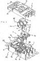
- FIG. 1 is an exploded perspective view showing a state in which a circuit breaker according to the first embodiment of the invention is exploded in a vertical direction.
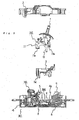
- Fig. 2 is a cross sectional view taken along the line A-A in Fig. 1 .
- Figs. 3 and 4 are enlarged views of a middle base in Fig. 1 .
- Fig. 3 is a plan view taken in a direction indicated by the arrow B of Fig. 1
- Fig. 4 is a side view taken in a direction indicated by the arrow C.
- Figs. 5 (a) and (b) are cross sectional views taken along the line D-D and the line E-E in Fig. 3 respectively.
- Fig. 1 shows an example of a three-pole circuit breaker having three voltage poles (hereinafter referred to as a circuit breaker).
- an insulating housing 101 is formed of three parts of a cover 2, a middle base 3, and a base 4.
- cover 2a In the above-mentioned cover 2, there are formed a handle window hole 2a through which an operating handle 1 extends, and a setting part window hole 2b through which a setting part 103a functioning to set, e.g., instantaneous trip current values of the below-described over-current trip device 103 that is mounted on the base 4.
- the over-current trip device 103 there are fixed or disposed the over-current trip device 103 as described above, and other moving contact part 104 connected with a cross bar 5, fixed contact 6 (refer to Fig. 2 ), arc-extinguishing device 7 and so on.
- the state (turning-on and resting position) of the moving contact 9 (refer to Fig. 2 ) and the operating handle 1, it is as known that the front (right side) is the side of a power supply, and the back (left side) is the load side in the plane of a paper.
- the assembly procedures of this circuit breaker are described referring to Fig. 2 .
- the fixed contact 6 is secured to the inner bottom face 4b of the base 4 with screws, not shown, and then a moving contact support 8 is also secured thereto with screws, not shown, along with the over-current trip device 103 in the state in which the moving contact 9 that is sandwiched between the moving contact supports 8 is connected in three poles with the cross bar 5 (corresponding to the above-described moving contact part 104).
- the arc-extinguishing device 7 is disposed in a predetermined position, and the middle base 3 is put on so as to cover the moving contact part 104.
- the make-and-break mechanism part 102 is mounted as described above.
- Frame plates 11 of the make-and-break mechanism part 102 are in opposition to each other (refer to Fig. 1 ), whereby the make-and-break mechanism part 102 is formed as a unit.
- This unit of make-and-break mechanism part 102 is secured by means of screws, not shown, from underside of the base 4 to pairs of threaded parts 11a, 11b, 11a, 11b (refer to Fig. 1 ) disposed at both ends (front and rear ends) of the frame plates 11 respectively.
- the screws of the threaded parts 11a and 11a go through second holes 3c and 3c of the middle base 3 (refer to Fig.
- grooves 3e and 3e are formed from the bases 3d and 3d to the first holes 3b and 3b on the line connecting the first holes 3b and 3b and the second holes 3c and 3c of the middle base 3 (one-dot-chain line).
- These grooves 3e and 3e are in conformity with the shape of the frame plates 11 notched in a substantially half circle (refer to Fig. 2 ) corresponding to the cross bar 5 being turned. That is, the semi-circular notch of the frame 11 will be in contact along the upper portion of the above-mentioned groove 3e.
- the threaded part 11a is in the proximity of the inner bottom face 4b of the base 4.
- the base 3d of the middle base 3 is disposed at a position near the lowermost end in a vertical direction on the plane of a drawing paper.
- the above-mentioned middle base 3 is removed, and alternatively, for example, a resin spacer is interposed instead of the base 3d, i.e., the middle base 3, thereby enabling the make-and-break mechanism part 102 to be secured without any change in layout or part structure of the breaking portion, the make-and-break mechanism part 102 and the over-current trip device 103, etc.
- Fig. 6 is an exploded perspective view of a circuit breaker when a middle base 3 is removed, and corresponds to Fig. 1 of when the middle base 3 is attached.
- numeral 20 designates spacers that are inserted between the threaded part 11a of the make-and-break mechanism part 102 and the bottom of the base 4, and secured with screws, not shown, from underside of the base 4.
- Numeral 21 designates spacers that are inserted between the threaded part 11b of the make-and-break mechanism part 102 and the bottom of the base 4, and secured with screws, not shown, from underside of the base 4.
- a numeral 22 designates a part corresponding to a side plate 3a of the middle base 3. Accordingly, also in the case where the middle base 3 is removed, it is possible to obtain a circuit breaker in which the above-mentioned breaking portion, make-and-break mechanism part, and over-current trip device are not separated from each other without any change in layout and part structure of these parts.
- a circuit breaker is more likely to be inexpensive as a rated breaking current thereof is smaller. Accordingly, each manufacturer is required to reduce the manufacturing cost of products of small rated breaking current.
- this comparatively expensive middle base 3 is not necessarily used, and a unit of make-and-break mechanism part 102 can also be used in a shared manner, thus enabling to obtain a circuit breaker of a manufacturing cost for a reasonable price.
- unemployment of a middle base 3 leads to the necessity of mounting such parts as the above-described spacers or side plates 3a and 3a (refer to Fig. 1 ), it is apparent that the addition of these parts gives no influence on manufacturing cost of this circuit breaker.
- the middle base 3 is provided with a horizontal part 3f and a vertical part 3g functioning as a partition wall. Therefore, the breaking portion that is formed of the cross bar 5, the fixed contact 6, the arc-extinguishing device 7 and the moving contact 9 is separated from the make-and-break mechanism part 102 with the horizontal part 3f; and the above-mentioned breaking portion is separated from the over-current trip device 103 with the vertical part 3g.
- the make-and-break mechanism part 102 and the over-current trip device 103 from the arc, hot air, molten material or soot that is generated from the breaking portion at the time of breaking.
- Fig. 7 is a perspective view showing a circuit breaker after assembly.
- reference numeral 25 designates an actuator.
- any auxiliary contact is not shown, normally it is constructed such that micro switches are mounted in the space above the mentioned actuators 25, and buttons of the micro switches are engaged with the actuators 25.
- an arc-extinguishing device holding part 3i (refer to Fig. 1 ) is provided at a position opposite to the above-mentioned arc-extinguishing device 7 of the middle base 3.
- a stopper 3j (refer to Fig. 5(a) ) is provided at a position opposite to the moving contact 9 of the middle base 3.
- the material of a middle base 3 is not necessarily the same as that of a cover 2 or a base 4. It is preferable to select any economical material, considering the function as the above-described partition wall or the function of absorbing impact.
- a three-pole circuit breaker is described as an example.
- an electric circuit is not limited to the three-pole type, and there is the one having voltage poles and a neutral pole, that is, a four-pole circuit breaker.
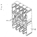
- a middle base 3 is applied to this four-pole circuit breaker, and is now described referring to Fig. 8.
- Fig. 8 is an external perspective view showing a state in which the middle base 3 is integrated into a base 24 of a four-pole circuit breaker according to the second embodiment of the invention.
- the configuration of the four-pole base 24, particularly the phase-to-phase configuration between voltage poles and a neutral pole may be determined so that a middle base 3 having been described in the first embodiment (i.e. tree-pole middle base 3) can be mounted onto the four-pole base 24.
- make-and-break mechanism part 102 is provided with pairs of threaded parts 11a, 11b, 11a, 11b at both ends (front and back ends) of frame plates 11 respectively, and secured thereto with screws from the underside of a base 4 are described.
- threaded mounting any other alternative fastening means may be employed as a matter of course.
Claims (9)
- Stromkreisunterbrecher mit:einem Unterbrechungsmechanismuselement (102), das einen Betätigungsgriff (1) aufweist,einer Basis (4) in der: eine Querstange (5), die sich zusammen mit dem Unterbrechungsmechanismuselement dreht, ein beweglicher Kontakt (9), der mit der Querstange zusammenwirkt, ein ortsfester Kontakt (6), der das in Kontakt bringen und das Trennen von dem beweglichen Kontakt wiederholt, ein Unterbrechungsabschnitt, der eine Bogenauslöschungseinrichtung (7), die zum Auslöschen eines zwischen den beiden Kontakten erzeugten Lichtbogens funktioniert, umfasst, und eine Überstromschalteinrichtung (103) enthalten sind;einer mittleren Basis (3) in der eine Trennwand (3f, 3g), die dazu dient den Unterbrechungsabschnitt von dem Unterbrechungsmechanismuselement und den Unterbrechungsabschnitt von der Überstromschalteinrichtung zu trennen, vorgesehen ist, und in der das Unterbrechungsmechanismuselement enthalten ist; undeiner Abdeckung (2) mit der die Basis, die mittlere Basis und alle Elemente, die in der Basis und der mittleren Basis enthalten sind, abgedeckt sind;
dadurch gekennzeichnet dass:das Unterbrechungsmechanismuselement zwischen einander gegenüberliegenden Rahmenplatten (11) angeordnet ist; unddie Rahmenplatten des Unterbrechungsmechanismuselements an einer inneren Bodenfläche (4b) der Basis durch die mittlere Basis hindurch so gesichert sind, dass die mittlere Basis entfernbar ist und so, dass die Rahmenplatten und die innere Bodenfläche der Basis direkt durch Abstandshalter sicherbar sind, wenn die mittlere Basis entfernt ist. - Stromkreisunterbrecher gemäß Anspruch 1, bei dem die Rahmenplatten mit Paaren von mit Gewinden versehenen Elementen (11a, 11b) versehen sind, um mittels Schrauben durch die mittlere Basis hindurch bzw. von der Unterseite der Basis her, gesichert zu werden; und ein Basiselement (3d) der mittleren Basis in Kontakt mit der inneren Bodenfläche (4b) der Basis steht.
- Stromkreisunterbrecher gemäß Anspruch 1 oder 2, bei dem die mittlere Basis versehen ist mit: einer ersten Öffnung (3b), durch welche eine untere Verbindung (10) des Unterbrechungsmechanismuselement führt, um mit der Querstange verbunden zu sein, und einer zweiten Öffnung (3c), die in dem Basiselement gebildet ist, und wobei die erste Öffnung schlitzförmig, entsprechend des Drehbereichs der unteren Verbindung, ist, wenn Unterbrechung der beiden Kontakte durch Drehung des Betätigungsgriffs ausgeführt wird.
- Stromkreisunterbrecher gemäß einem der vorangegangenen Ansprüche, bei dem eine Trennwand der mittleren Basis aus einem horizontalen Teil (3f), um den Unterbrechungsabschnitt von dem Unterbrechungsmechanismuselement zu trennen, und einem vertikalen Element (3g), um den Unterbrechungsabschnitt von dem Überstromschalteinrichtung zu trennen, besteht.
- Stromkreisunterbrecher gemäß Anspruch 4, bei dem die mittlere Basis ferner mit einer dritten Öffnung (3h) versehen ist, die in dem horizontalen Element (3f) der Trennwand ausgebildet ist, und durch die ein Vorsprung (5b), der an der Querstange ausgebildet ist, führt; und wobei die Öffnung schlitzförmig, entsprechend des Drehbereichs der Querstange, ist.
- Stromkreisunterbrecher gemäß einem der vorangegangenen Ansprüche, bei dem Seitenplatten (3a), die an zwei Seitenflächen der mittleren Basis parallel zu einer Richtung eines elektrischen Stromkreises des Stromkreisunterbrechers vorgesehen sind, in konkave Abschnitte (4a), die in der Basis ausgebildet sind, eingepasst sind, wobei die mittlere Basis ein Element eines isolierenden Gehäuses (101) des Stromkreisunterbrechers bildet.
- Stromkreisunterbrecher gemäß einem der vorangegangenen Ansprüche, bei dem ein Bogenauslöschungseinrichtunghalteelement (3i) der mittleren Basis an einer Position gegenüber der Bogenauslöschungseinrichtung vorgesehen ist.
- Stromkreisunterbrecher gemäß einem der vorangegangenen Ansprüche, bei dem ein Stopper (3j) an einer Position gegenüber des beweglichen Kontakts der mittleren Basis vorgesehen ist.
- Stromkreisunterbrecher gemäß einem der vorangegangenen Ansprüche, bei dem im Fall der Bildung eines vierpoligen Stromkreisunterbrechers, der drei Spannungspole und einen Neutralpol aufweist, die mittlere Basis auf den Spannungspolen angebracht ist.
Applications Claiming Priority (1)
| Application Number | Priority Date | Filing Date | Title |
|---|---|---|---|
| JP2005368020A JP4522362B2 (ja) | 2005-12-21 | 2005-12-21 | 回路遮断器 |
Publications (3)
| Publication Number | Publication Date |
|---|---|
| EP1801835A2 EP1801835A2 (de) | 2007-06-27 |
| EP1801835A3 EP1801835A3 (de) | 2008-12-17 |
| EP1801835B1 true EP1801835B1 (de) | 2013-05-15 |
Family
ID=36649642
Family Applications (1)
| Application Number | Title | Priority Date | Filing Date |
|---|---|---|---|
| EP06012668.7A Expired - Fee Related EP1801835B1 (de) | 2005-12-21 | 2006-06-20 | Schutzschalter |
Country Status (5)
| Country | Link |
|---|---|
| US (1) | US7482901B2 (de) |
| EP (1) | EP1801835B1 (de) |
| JP (1) | JP4522362B2 (de) |
| KR (1) | KR100807425B1 (de) |
| CN (1) | CN1988096B (de) |
Families Citing this family (20)
| Publication number | Priority date | Publication date | Assignee | Title |
|---|---|---|---|---|
| JP4821793B2 (ja) * | 2008-03-31 | 2011-11-24 | 三菱電機株式会社 | 回路遮断器 |
| US8995677B2 (en) | 2008-09-03 | 2015-03-31 | Apple Inc. | Accessory controller for electronic devices |
| EP2462609B1 (de) * | 2009-08-04 | 2012-10-24 | Abb Ab | Schaltvorrichtung |
| EP2462607B1 (de) * | 2009-08-04 | 2012-10-31 | Abb Ab | Schaltvorrichtung |
| KR101245593B1 (ko) * | 2009-10-07 | 2013-03-20 | 엘에스산전 주식회사 | 배선용 차단기의 개폐기구 |
| KR101026306B1 (ko) * | 2009-10-20 | 2011-03-31 | 엘에스산전 주식회사 | 순시 트립 기구를 가진 배선용차단기 |
| KR101031947B1 (ko) | 2009-11-05 | 2011-04-29 | 엘에스산전 주식회사 | 회로 차단기의 메커니즘부 고정 장치 |
| US20110132875A1 (en) * | 2009-12-07 | 2011-06-09 | Eaton Corporation | Splatter resistance in circuit breakers |
| JP5327038B2 (ja) * | 2009-12-24 | 2013-10-30 | 三菱電機株式会社 | 回路遮断器 |
| KR101082204B1 (ko) * | 2010-04-16 | 2011-11-09 | 엘에스산전 주식회사 | 배선용차단기의 개폐기구 측판 들림 방지기구 |
| JP5655452B2 (ja) * | 2010-09-15 | 2015-01-21 | 富士電機機器制御株式会社 | 回路遮断器 |
| JP5508537B2 (ja) * | 2010-09-22 | 2014-06-04 | パナソニック株式会社 | 複合開閉装置及び該複合開閉装置に使用される開閉装置モジュール |
| JP5845698B2 (ja) * | 2011-08-04 | 2016-01-20 | 富士電機機器制御株式会社 | 回路遮断器 |
| KR101255475B1 (ko) * | 2011-11-10 | 2013-04-16 | 엘에스산전 주식회사 | 배선용 차단기 |
| JP5747806B2 (ja) * | 2011-12-14 | 2015-07-15 | 三菱電機株式会社 | 回路遮断器 |
| KR101276369B1 (ko) * | 2012-01-10 | 2013-06-18 | 현대중공업 주식회사 | 배선용 차단기 |
| WO2013171903A1 (ja) * | 2012-05-18 | 2013-11-21 | 三菱電機株式会社 | 直流回路用回路遮断器及び直流回路用回路遮断装置 |
| CN104835691B (zh) * | 2015-03-04 | 2016-09-28 | 浙江天正电气股份有限公司 | 一种通用基座与应用该基座的热磁式和电子式塑壳断路器 |
| KR20180099330A (ko) | 2017-02-28 | 2018-09-05 | 엘에스산전 주식회사 | 주접점 인터록 기능을 갖는 배선용 차단기 |
| JP7289100B2 (ja) * | 2019-07-22 | 2023-06-09 | パナソニックIpマネジメント株式会社 | 漏電保護装置、及び分電盤 |
Family Cites Families (20)
| Publication number | Priority date | Publication date | Assignee | Title |
|---|---|---|---|---|
| US3354415A (en) * | 1965-07-20 | 1967-11-21 | Square D Co | Multiple contact electromagnetically actuated switch and accessories therefor |
| FR2451097A1 (fr) * | 1979-02-07 | 1980-10-03 | Terasaki Denki Sangyo Kk | Interrupteur de circuit electrique a air, mecanisme et boitier |
| EP0225207B1 (de) * | 1985-10-31 | 1991-05-15 | Merlin Gerin | Kinematische Übertragungskette zwischen dem Steuermechanismus und den Polen eines elektrischen Lastschalters mit einem gespritzten Isoliergehäuse |
| JPH06111707A (ja) * | 1992-09-29 | 1994-04-22 | Mitsubishi Electric Corp | 回路遮断器 |
| JPH07141976A (ja) * | 1993-11-15 | 1995-06-02 | Toshiba Corp | 回路遮断器 |
| JP3432327B2 (ja) * | 1995-03-30 | 2003-08-04 | 寺崎電気産業株式会社 | 回路遮断器 |
| JP3414908B2 (ja) * | 1995-10-31 | 2003-06-09 | 富士電機株式会社 | 回路遮断器の消弧装置 |
| JP3447486B2 (ja) * | 1996-10-16 | 2003-09-16 | 三菱電機株式会社 | 回路遮断器の開閉機構 |
| US6005206A (en) * | 1998-05-07 | 1999-12-21 | Eaton Corporation | Electrical switching apparatus with improved contact arm carrier arrangement |
| FR2780549B1 (fr) * | 1998-06-24 | 2000-09-08 | Schneider Electric Ind Sa | Disjoncteur multipolaire basse tension de tenue electrodynamique elevee, dont l'arbre des poles est dispose dans le compartiment de logement des poles |
| JP4265725B2 (ja) * | 1998-12-28 | 2009-05-20 | 三菱電機株式会社 | 限流装置および限流機能を有する回路遮断器 |
| JP3997664B2 (ja) * | 1999-08-23 | 2007-10-24 | 富士電機機器制御株式会社 | 回路しゃ断器 |
| CN1222966C (zh) * | 1999-12-02 | 2005-10-12 | 三菱电机株式会社 | 回路断路器 |
| US6373357B1 (en) | 2000-05-16 | 2002-04-16 | General Electric Company | Pressure sensitive trip mechanism for a rotary breaker |
| JP4126865B2 (ja) * | 2000-10-30 | 2008-07-30 | 富士電機機器制御株式会社 | 回路しゃ断器 |
| JP4428076B2 (ja) | 2004-02-16 | 2010-03-10 | 富士電機機器制御株式会社 | 回路遮断器 |
| JP2006073200A (ja) * | 2004-08-31 | 2006-03-16 | Fuji Electric Fa Components & Systems Co Ltd | 回路遮断器 |
| JP4650023B2 (ja) * | 2005-02-25 | 2011-03-16 | 富士電機機器制御株式会社 | 回路遮断器 |
| JP2007052942A (ja) * | 2005-08-16 | 2007-03-01 | Fuji Electric Holdings Co Ltd | 回路遮断器 |
| JP4291805B2 (ja) * | 2005-08-29 | 2009-07-08 | 株式会社日立産機システム | 回路遮断器 |
-
2005
- 2005-12-21 JP JP2005368020A patent/JP4522362B2/ja active Active
-
2006
- 2006-06-08 US US11/448,710 patent/US7482901B2/en active Active
- 2006-06-15 KR KR1020060053915A patent/KR100807425B1/ko active IP Right Grant
- 2006-06-20 EP EP06012668.7A patent/EP1801835B1/de not_active Expired - Fee Related
- 2006-08-24 CN CN2006101119314A patent/CN1988096B/zh active Active
Also Published As
| Publication number | Publication date |
|---|---|
| CN1988096A (zh) | 2007-06-27 |
| US20070139147A1 (en) | 2007-06-21 |
| EP1801835A2 (de) | 2007-06-27 |
| EP1801835A3 (de) | 2008-12-17 |
| JP2007172980A (ja) | 2007-07-05 |
| JP4522362B2 (ja) | 2010-08-11 |
| US7482901B2 (en) | 2009-01-27 |
| KR20070066828A (ko) | 2007-06-27 |
| CN1988096B (zh) | 2010-10-06 |
| KR100807425B1 (ko) | 2008-02-25 |
Similar Documents
| Publication | Publication Date | Title |
|---|---|---|
| EP1801835B1 (de) | Schutzschalter | |
| US7535327B2 (en) | Circuit breaker | |
| JP3334520B2 (ja) | 直流遮断器 | |
| EP2180487B1 (de) | Mikroschalter | |
| US8390406B2 (en) | Mold cased circuit breaker | |
| JP4760898B2 (ja) | 回路遮断器 | |
| JP5845698B2 (ja) | 回路遮断器 | |
| JP2009140838A (ja) | 回路遮断器 | |
| US7830232B2 (en) | Arc runner assembly and electrical switching apparatus and method incorporating same | |
| ITMI20011326A1 (it) | Polo interruttore miniaturizzato | |
| JP2009245731A (ja) | 回路遮断器 | |
| KR200196838Y1 (ko) | 누전차단기 | |
| JP4147347B2 (ja) | 配線用遮断器 | |
| US11404225B2 (en) | Low-voltage circuit breaker | |
| JPS62229631A (ja) | 回路しや断器 | |
| KR20040070544A (ko) | 배선용 차단기의 트립장치 | |
| JP3035548U (ja) | 開閉器の消弧室 | |
| JP4090968B2 (ja) | 回路遮断器 | |
| KR200428491Y1 (ko) | 모터보호용 차단기의 트립아세이 고정장치 | |
| JPH09161644A (ja) | 回路遮断器 | |
| JPH0156491B2 (de) | ||
| KR102527008B1 (ko) | 배선용 차단기의 트립 어셈블리 | |
| JPH05250976A (ja) | 回路遮断器 | |
| KR200411500Y1 (ko) | 배선용 차단기의 소호장치 | |
| KR200224235Y1 (ko) | 배선용차단기의소호장치 |
Legal Events
| Date | Code | Title | Description |
|---|---|---|---|
| PUAI | Public reference made under article 153(3) epc to a published international application that has entered the european phase |
Free format text: ORIGINAL CODE: 0009012 |
|
| AK | Designated contracting states |
Kind code of ref document: A2 Designated state(s): AT BE BG CH CY CZ DE DK EE ES FI FR GB GR HU IE IS IT LI LT LU LV MC NL PL PT RO SE SI SK TR |
|
| AX | Request for extension of the european patent |
Extension state: AL BA HR MK YU |
|
| PUAL | Search report despatched |
Free format text: ORIGINAL CODE: 0009013 |
|
| AK | Designated contracting states |
Kind code of ref document: A3 Designated state(s): AT BE BG CH CY CZ DE DK EE ES FI FR GB GR HU IE IS IT LI LT LU LV MC NL PL PT RO SE SI SK TR |
|
| AX | Request for extension of the european patent |
Extension state: AL BA HR MK RS |
|
| 17P | Request for examination filed |
Effective date: 20090213 |
|
| 17Q | First examination report despatched |
Effective date: 20090401 |
|
| AKX | Designation fees paid |
Designated state(s): DE FR |
|
| GRAP | Despatch of communication of intention to grant a patent |
Free format text: ORIGINAL CODE: EPIDOSNIGR1 |
|
| GRAS | Grant fee paid |
Free format text: ORIGINAL CODE: EPIDOSNIGR3 |
|
| GRAA | (expected) grant |
Free format text: ORIGINAL CODE: 0009210 |
|
| AK | Designated contracting states |
Kind code of ref document: B1 Designated state(s): DE FR |
|
| REG | Reference to a national code |
Ref country code: DE Ref legal event code: R096 Ref document number: 602006036244 Country of ref document: DE Effective date: 20130711 |
|
| PLBE | No opposition filed within time limit |
Free format text: ORIGINAL CODE: 0009261 |
|
| STAA | Information on the status of an ep patent application or granted ep patent |
Free format text: STATUS: NO OPPOSITION FILED WITHIN TIME LIMIT |
|
| 26N | No opposition filed |
Effective date: 20140218 |
|
| REG | Reference to a national code |
Ref country code: DE Ref legal event code: R097 Ref document number: 602006036244 Country of ref document: DE Effective date: 20140218 |
|
| REG | Reference to a national code |
Ref country code: FR Ref legal event code: PLFP Year of fee payment: 11 |
|
| REG | Reference to a national code |
Ref country code: DE Ref legal event code: R084 Ref document number: 602006036244 Country of ref document: DE |
|
| REG | Reference to a national code |
Ref country code: FR Ref legal event code: PLFP Year of fee payment: 12 |
|
| REG | Reference to a national code |
Ref country code: FR Ref legal event code: PLFP Year of fee payment: 13 |
|
| PGFP | Annual fee paid to national office [announced via postgrant information from national office to epo] |
Ref country code: DE Payment date: 20210525 Year of fee payment: 16 Ref country code: FR Payment date: 20210513 Year of fee payment: 16 |
|
| REG | Reference to a national code |
Ref country code: DE Ref legal event code: R119 Ref document number: 602006036244 Country of ref document: DE |
|
| PG25 | Lapsed in a contracting state [announced via postgrant information from national office to epo] |
Ref country code: FR Free format text: LAPSE BECAUSE OF NON-PAYMENT OF DUE FEES Effective date: 20220630 |
|
| PG25 | Lapsed in a contracting state [announced via postgrant information from national office to epo] |
Ref country code: DE Free format text: LAPSE BECAUSE OF NON-PAYMENT OF DUE FEES Effective date: 20230103 |