EP1800802B1 - Electric driver and controller for the same - Google Patents
Electric driver and controller for the same Download PDFInfo
- Publication number
- EP1800802B1 EP1800802B1 EP05768492.0A EP05768492A EP1800802B1 EP 1800802 B1 EP1800802 B1 EP 1800802B1 EP 05768492 A EP05768492 A EP 05768492A EP 1800802 B1 EP1800802 B1 EP 1800802B1
- Authority
- EP
- European Patent Office
- Prior art keywords
- signal
- rotation
- reverse
- screwdriver
- switch
- Prior art date
- Legal status (The legal status is an assumption and is not a legal conclusion. Google has not performed a legal analysis and makes no representation as to the accuracy of the status listed.)
- Expired - Lifetime
Links
Images

Classifications
-
- B—PERFORMING OPERATIONS; TRANSPORTING
- B25—HAND TOOLS; PORTABLE POWER-DRIVEN TOOLS; MANIPULATORS
- B25B—TOOLS OR BENCH DEVICES NOT OTHERWISE PROVIDED FOR, FOR FASTENING, CONNECTING, DISENGAGING OR HOLDING
- B25B23/00—Details of, or accessories for, spanners, wrenches, screwdrivers
- B25B23/14—Arrangement of torque limiters or torque indicators in wrenches or screwdrivers
-
- H—ELECTRICITY
- H02—GENERATION; CONVERSION OR DISTRIBUTION OF ELECTRIC POWER
- H02P—CONTROL OR REGULATION OF ELECTRIC MOTORS, ELECTRIC GENERATORS OR DYNAMO-ELECTRIC CONVERTERS; CONTROLLING TRANSFORMERS, REACTORS OR CHOKE COILS
- H02P7/00—Arrangements for regulating or controlling the speed or torque of electric DC motors
- H02P7/06—Arrangements for regulating or controlling the speed or torque of electric DC motors for regulating or controlling an individual DC dynamo-electric motor by varying field or armature current
- H02P7/18—Arrangements for regulating or controlling the speed or torque of electric DC motors for regulating or controlling an individual DC dynamo-electric motor by varying field or armature current by master control with auxiliary power
- H02P7/24—Arrangements for regulating or controlling the speed or torque of electric DC motors for regulating or controlling an individual DC dynamo-electric motor by varying field or armature current by master control with auxiliary power using discharge tubes or semiconductor devices
- H02P7/28—Arrangements for regulating or controlling the speed or torque of electric DC motors for regulating or controlling an individual DC dynamo-electric motor by varying field or armature current by master control with auxiliary power using discharge tubes or semiconductor devices using semiconductor devices
- H02P7/285—Arrangements for regulating or controlling the speed or torque of electric DC motors for regulating or controlling an individual DC dynamo-electric motor by varying field or armature current by master control with auxiliary power using discharge tubes or semiconductor devices using semiconductor devices controlling armature supply only
- H02P7/29—Arrangements for regulating or controlling the speed or torque of electric DC motors for regulating or controlling an individual DC dynamo-electric motor by varying field or armature current by master control with auxiliary power using discharge tubes or semiconductor devices using semiconductor devices controlling armature supply only using pulse modulation
-
- B—PERFORMING OPERATIONS; TRANSPORTING
- B25—HAND TOOLS; PORTABLE POWER-DRIVEN TOOLS; MANIPULATORS
- B25B—TOOLS OR BENCH DEVICES NOT OTHERWISE PROVIDED FOR, FOR FASTENING, CONNECTING, DISENGAGING OR HOLDING
- B25B21/00—Portable power-driven screw or nut setting or loosening tools; Attachments for drilling apparatus serving the same purpose
-
- B—PERFORMING OPERATIONS; TRANSPORTING
- B25—HAND TOOLS; PORTABLE POWER-DRIVEN TOOLS; MANIPULATORS
- B25B—TOOLS OR BENCH DEVICES NOT OTHERWISE PROVIDED FOR, FOR FASTENING, CONNECTING, DISENGAGING OR HOLDING
- B25B23/00—Details of, or accessories for, spanners, wrenches, screwdrivers
-
- B—PERFORMING OPERATIONS; TRANSPORTING
- B25—HAND TOOLS; PORTABLE POWER-DRIVEN TOOLS; MANIPULATORS
- B25B—TOOLS OR BENCH DEVICES NOT OTHERWISE PROVIDED FOR, FOR FASTENING, CONNECTING, DISENGAGING OR HOLDING
- B25B23/00—Details of, or accessories for, spanners, wrenches, screwdrivers
- B25B23/14—Arrangement of torque limiters or torque indicators in wrenches or screwdrivers
- B25B23/147—Arrangement of torque limiters or torque indicators in wrenches or screwdrivers specially adapted for electrically operated wrenches or screwdrivers
-
- H—ELECTRICITY
- H02—GENERATION; CONVERSION OR DISTRIBUTION OF ELECTRIC POWER
- H02P—CONTROL OR REGULATION OF ELECTRIC MOTORS, ELECTRIC GENERATORS OR DYNAMO-ELECTRIC CONVERTERS; CONTROLLING TRANSFORMERS, REACTORS OR CHOKE COILS
- H02P7/00—Arrangements for regulating or controlling the speed or torque of electric DC motors
- H02P7/03—Arrangements for regulating or controlling the speed or torque of electric DC motors for controlling the direction of rotation of DC motors
- H02P7/04—Arrangements for regulating or controlling the speed or torque of electric DC motors for controlling the direction of rotation of DC motors by means of a H-bridge circuit
Definitions
- the present invention relates to an electric screwdriver and a controller thereof.
- the electric screwdriver equipped with a controller having a function for preventing any screws from being left not tightened.
- the electric screwdriver in this type, is connected to the controller, so that when a tightening torque has reached a value equal to or greater than a predetermined value in a tightening operation, a signal indicating the completion of screw-tightening is sent from the electric screwdriver to the controller, and then the controller causes a specific counter (a counter for counting a number of screws tightened) to increment by one to provide a count indication of the number of tightened screws or inform a situation that the number of tightened screws has reached a predetermined one (see, for example, patent documents No.1 - No.3).
- a typical (in most cases, minimal) tightening time expected in the normal tightening operation is previously set as a reference time in the controller, such that if the signal indicating the completion of the tightening is generated by the electric screwdriver in a shorter time than the reference time, then the controller can determine that the screw must have been tightened in the inclined state or a once tightened screw has been tightened again (for additional tightening).
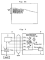
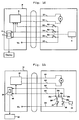
- Fig. 9 shows a typical wiring diagram in an electric screwdriver D comprising a controller P with a function for preventing any screws from being left not tightened.
- "D1" and “D2" designate power source lines to a screwdriver motor M
- "D3" is an start/stop signal line
- "D4" is a tightening completion signal line
- "D5" is a common line.
- the common line is connected to a reference voltage Vs.
- the power source lines D1 and D2 are connected to a power supply circuit S of the controller P.
- the screwdriver motor M is a type of direct-current motor and the power circuit S comprises a direct-current power source.
- RS designates a normal/reverse rotation select switch for changing the polarity of the power source output voltage in order to select the rotation direction of the motor M (normal or reverse rotation).
- SS designates a starting switch, which in response to an open/close operation by an operator, sends a start/stop signal to the power circuit S via the start/stop signal line D3. For example, when the starting switch SS is closed, the reference voltage Vs from the common line D5 is applied to the power circuit S as the start signal, whereas when the starting switch is opened, the reference voltage Vs from the common line D5 is shut off, and the stop signal is sent to the power supply circuit by the shut-off.
- BS designates a braking switch of a normally open type, which is shifted to a closed position by an action of a cam C incorporated in the screwdriver when the load torque in the tightening operation has reached a predetermined value.
- Vs a tightening completion signal at the reference voltage Vs is sent to a counter T for counting the number of tightened screws and also to the power supply circuit S in the controller P via the tightening completion signal line D4.
- the circuit shown in Fig. 9 is not able to provide the signal from the electric driver D to the controller P to reverse the count in the counter T in a micro computer A for counting the number of the tightened screws when the user drives the electric screwdriver D in reverse direction to untighten the screw that has been tightened incorrectly as discussed above.
- the circuit configuration of the electric screwdriver D is modified as such as shown in Fig. 10 .
- the normal/reverse rotation selection switch RS is moved from the motor power source lines D1 and D2 to signal line D5 and replaced by an ON/OFF switch, wherein the power source circuit in the controller P may be provided with normal/reverse changing function.
- the normal/reverse rotation selection switch RS may be turned to ON position (closed state), for example, so as to send a signal (ON signal) of the reference voltage Vs from the common line D6 to the power supply circuit S in the controller P through the signal line D5 as a reverse rotation control signal, and to cause the power supply circuit S to invert the polarity of the output voltage (motor driving voltage), while at the same time sending the same ON signal to the counter T to reverse the count back.
- WO 03 045 635 A1 related to a system for ensuring proper completion of tasks at a plurality of locations for example on a CNC machine.
- the apparatus ensures proper completion of a plurality of tasks at the plurality of positions, such as torquing of a plurality of bolts on a structure to for example mount a workpiece for CNC machining, wherein the bolts are to be torqued to a plurality of different torques.
- the apparatus includes first indicia adjacent to each bolt.
- the indicia are characteristic of the torque to which each bolt is to be tightened.
- At least one torque wrench is provided for tightening each bolt.
- the second indicia are operatively coupled to the wrench and to the reading device which indicates when the torque wrench properly tightens each bolt.
- DE 35 36 416 A1 relates to a control device for the electric current which is to be supplied to a DC motor, in particular the DC motor of a tool such as a screw driver.
- the electric current is to be supplied in the form of rectangular pulses from a DC source having a low operating voltage.
- the rotation speed of the motor which is constructed especially as a DC permanent-magnet motor, is determined via the duty ratio of the current pulses.
- the present invention is directed to solve the above- problems.
- the present invention provides an electric screwdriver device as set forth in claim 1 or 4. Further embodiments of the invention are inter alia disclosed in the dependent claims.
- the electric screwdriver device comprises an electric screwdriver and a controller connected to said electric screwdriver, in which said controller comprises: a direct-current power source and a power circuit for said direct-current power source, said power circuit having a function for performing a switching operation of the polarity of a power source terminal of said direct-current power source between a state for a normal rotation and a state for a reverse rotation in accordance with a normal rotation signal or a reverse rotation signal generated by said electric screwdriver and for shutting down an output from said direct-current power source in accordance with a stop signal of said electric screwdriver or a tightening completion signal generated by said electric screwdriver; and a tightening completion signal and reverse rotation signal processing means for processing said tightening completion signal and said reverse rotation signal, characterized in that, said electric screwdriver comprises:
- This electric screwdriver device may be configured specifically such that said tightening completion signal and reverse rotation signal processing means comprises a tightening operation counter adapted to start counting upon receipt of the tightening completion signal and to reverse the counting upon receipt of the reverse rotation signal.
- the present invention provides an electric screwdriver device comprising an electric screwdriver and a controller connected to said electric screwdriver, in which said controller has a power circuit comprising a direct-current power source, and said electric screwdriver has a screwdriver motor having a power source connecting +/- line to be connected to a power source terminal of said power circuit, said screwdriver motor being a direct-current motor of brush type, and said power circuit having a power circuit control section, said electric screwdriver device being characterized in that, said power circuit control section comprises:
- the present invention has made it possible to generate the signal for reversing a counting by the counter for counting the number of tightened screws in the controller without increasing the number of signal lines as compared to the conventional electric screwdriver, said signal being required when a screw has not been correctly screwed-down and that screw has been rotated reversely and removed, therefore any complication and cost increase, which otherwise would be caused by increased number of lines, could be avoided.
- the present invention allows for the expected time of tightening (reference time) to be taken as a reference for determining whether or not the tightening operation has been successfully completed to be determined automatically by simply conducting a tightening test for a certain number of screws rather than by using a stopwatch as practiced conventionally, and thus determined expected time can be set in the controller.
- the OFF time is kept for a certain period but the ON time is varied in dependence on the number of revolutions of the motor or the magnitude of the current flowing through the braking short circuit, therefore the braking short circuit can be operated efficiently so as to provide an efficient braking in a short time.
- PWM pulse width modulation
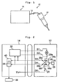
- an electric screwdriver device 10 comprises an electric screwdriver 12 and a screwdriver controller 14 connected to the electric screwdriver via a cable 13 and having a function for preventing any screws from being left not tightened.
- the electric screwdriver 12 has an electric circuit (electric screwdriver circuit) as shown in Fig. 2 in association with the function for preventing any screws from being left not tightened.
- the illustrated electric screwdriver circuit is intended to solve the problems in conjunction with the prior art as set forth above with reference to Figs. 9 and 10 .
- the circuit comprises power source lines D1 and D2 for supplying a drive voltage to a screwdriver motor M, a first and a second signal lines D3 and D4 for sending an appropriate signal from the electric screwdriver 12 to the controller 14, and a common line D5 for generating an appropriate signal onto the first and the second signal lines D3 and D4.
- the common line D5 is connected to a reference voltage Vs.
- this electric screwdriver circuit has a normal rotation/reverse-rotation shifting switch 28.
- the normal rotation/reverse-rotation shifting switch 28 has fixed contacts 28a, 28b, 28c and 28d and movable contacts 28e and 28f.
- the fixed contact 28a is connected to the fixed contact 28d and the fixed contact 28b is connected to the fixed contact 28c.
- One of the movable contacts 28f is connectable to the common line D5 via a starting switch 20, and the other of the movable contacts 28e is connectable to the common line D5 via a braking switch 26 and the starting switch 20.
- the normal rotation/reverse-rotation shifting switch 28 is adapted to be manually shifted by an operator between a normal rotation connecting position ( Fig.
- the starting switch 20 is an ON/OFF switch intended to send a start/stop signal in response to the manual operation by the operator to the controller 14. If the starting switch 20 is closed (ON) under the condition where the normal rotation/reverse-rotation shifting switch 28 is in the normal rotation connecting position as illustrated, the signal (ON signal) at the reference voltage Vs from the common line D5 is sent from the starting switch 20 to the first signal line D3 via the movable contact 28f and the fixed contacts 28d and 28a of the normal rotation/reverse-rotation shifting switch 28, and through the first signal line D3, the signal is passed to a power circuit 32 of the controller 14 as the start signal. A microcomputer 40 in the controller 14 is shifted to the normal rotation mode in response to a receipt of the start signal through the first signal line D3. If the starting switch 20 is shifted to an open state (OFF), the signal at the reference voltage Vs from the common line D5 is shut off, and this is given as the stop signal to the power circuit 32 of the controller 14.
- the starting switch is turned into the closed state (ON) under the condition where the normal rotation/reverse-rotation shifting switch 28 is in the reverse rotation connecting position
- the signal (ON signal) at the reference voltage Vs from the common line D5 is sent from the starting switch 20 to the second signal line D4 via the movable contact 28f and the fixed contact 28b of the normal rotation/reverse-rotation shifting switch 28, and through the second signal line D4, the signal is passed to the power circuit 32 of the controller 14 as the start signal (i.e., the reverse rotation signal).
- the microcomputer 40 of the controller 14 is shifted to the reverse rotation mode in response to the receipt of the same ON signal through the second signal line D4, and a counter for counting the number of tightened screws in the microcomputer 40 now in this mode carries out the reverse counting by decreasing the count value by one. Furthermore, in the reverse rotation mode, as is the case with the normal rotation mode, if the starting switch 20 is shifted to the open state (OFF), the ON signal at the reference voltage Vs from the common line D5 is shut off thereby providing the stop signal to the power circuit 32 of the controller 14.
- the braking switch 26 is a normal-open type switch and adapted to be shifted to the closed state by a cam 29 incorporated in the screwdriver 12, which is activated when the load torque in the tightening operation has reached a predetermined value.
- the braking switch 26 is closed, the tightening completion signal is sent from the screwdriver 12 to the controller 14.
- the signal at the reference voltage Vs from the common line D5 is sent from the braking switch 26 to the second signal line D4 via the movable contact 28e and the fixed contacts 28c and 28b of the normal rotation/reverse-rotation shifting switch 28 as the tightening completion signal and through the second signal line D4, the signal is sent to the screwdriver controller 14.
- the power circuit 32 is activated in response to the tightening completion signal from the second signal line D4 to shut down the output of the motor driving voltage and to make a short circuit of the power source lines D1 and D2 to apply the braking action to the screwdriver motor M.
- the counter 34 for counting the number of tightened screws in the microcomputer 40 is caused to increase the count value by one.
- Fig. 2 shows the configuration in which the start signal, the stop signal and the tightening completion signal are to be supplied directly from the respective signal lines to the power circuit 32 within the screwdriver controller 14, another configuration may be contemplated, in which the microcomputer 40 once receives all of the signals from the electric screwdriver 12 so as to control the power circuit 32.
- start signal reference voltage Vs
- motor driving voltage having the polarity for the normal rotation
- the braking switch 26 is closed by the cam 29 (which is activated by the rotationally driven shaft of the electric screwdriver), and the tightening completion signal is sent to the power circuit 32 and the microcomputer 40 (and thus to the counter 34 for counting the number of tightened screws) within the screwdriver control device 14.
- any required actions such as stopping or shutting off of the output of the motor driving voltage, is carried out, while in the counter 34, the counting is carried out under the assumption that one of the screws has been tightened.
- the counting result i.e., the count value or the accumulated number of screws that have been tightened
- the operator may shift the normal rotation/reverse-rotation shifting switch 28 to the reverse-rotation connecting position so as to close the starting switch 20 and thus to cause the starting signal (i.e., the reverse rotation signal) to be sent via the second signal line D4 and thereby cause the power circuit 32 of the controller 14 to invert the output polarity, which in turn drives the motor M in the direction for reverse rotation to turn the screw, that has been once tightened, in the loosening direction for removing the screw.
- the reverse rotation signal is sent to the counter 34, where the count is reversed to modify the counting of the number of tightened screws.
- the present invention allows the counter for counting the number of tightened screws in the controller to have a function for reversing the count in association with the reverse rotation of the electric screwdriver without increasing a number of signal lines from the electric screwdriver to the controllers.
- circuit wiring of the electric screwdriver illustrated in Fig. 2 has been developed in order to solve problems (which will be discussed below) found in the circuit wiring as shown in Fig. 11 , which had been initially developed by the inventor of the present invention to solve the problems as pointed out with reference to Figs. 9 and 10 .
- the electric screwdriver has power source lines D1 and D2 for the screwdriver motor M, the first and the second signal lines D3 and D4, and the common line D5, like the one as shown in Fig. 2 .
- the common line D5 is fixed at the reference voltage Vs (e.g., 0 volt).
- this electric wiring has the normal rotation/reverse-rotation shifting switch 28.
- the normal rotation/reverse-rotation shifting switch 28 includes the fixed contacts 28a, 28b, 28c and 28d, and the movable contacts 28e and 28f.
- the fixed contact 28b is connected to the fixed contact 28c.
- the movable contact 28f is connected to the common line D5 via the starting switch 20, while the movable contact 28e is connected to the common line D5 via the braking switch 26.
- the normal rotation/reverse-rotation shifting switch 28 is adapted to be shift between the normal rotation connecting position ( Fig. 11 ) where the movable contacts 28e and 28f are connected to the fixed contacts 28a and 28c respectively and the reverse rotation connecting position (not shown) where the movable contacts 28e and 28f are connected to the fixed contacts 28b and 28d respectively.
- Respective actions in the controller 14 including the activation, the reverse rotation, the normal counting and reverse counting of the number of tightened screws and so on based on the operations of the starting switch 20, the braking switch 26 and the normal rotation/reverse-rotation shifting switch 28 are carried out in a similar manner to that in the circuit shown in Fig. 2 .
- the problems in this circuit wiring are those as described below.
- the cam 29 has a raised portion which turns the braking switch 26 on when any excessive loading occurs. After setting the normal rotation or reverse-rotation by the normal rotation/reverse-rotation shifting switch, the starting switch is turned ON to carry out the tightening operation. In the tightening operation, when the braking switch is turned on, occasionally the braking switch could be held in the ON position by the raised portion of the cam.
- the CPU in the microcomputer of the controller 14 determines that in a subsequent program cycle, the normal rotation or reverse rotation has been set by the rotation/reverse-rotation switch and the starting switch has been turned on, thereby activating the screwdriver in spite of the fact that the starting switch is actually not turned on.
- the circuit wiring of Fig. 2 even if the braking switch is in such a condition as described above, the starting switch arranged in series with the braking switch is held in the OFF position, and thus no problem will occur.
- a reference value is determined in order to enable the determination whether or not the screw has been tightened correctly without being inclined.
- a tightening operation time is used as a reference to make the determination whether or not the tightening operation has been carried out correctly without causing the screw to be inclined or out of upright. This takes advantage of the fact that if the screw has been tightened out of upright, the tightening torque is increased more rapidly than that in the normal tightening operation to generate the tightening completion signal earlier.
- the tightening operation test is carried out for the predetermined number of screws prior to the actual tightening operation without requesting the operator to conduct a cumbersome process, wherein the time consumed for each correct tightening operation is measured and the minimal value is taken as the reference value for the tightening operation time.
- the microcomputer 40 in the controller 14 determines the reference value of the tightening operation time based on the tightening completion signal and the like from the electric screwdriver in this tightening operation test in a manner as will be described below.
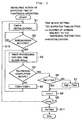
- Fig. 3 is a flow chart illustrating a procedure by the microcomputer 40 to determine the reference value for the tightening operation time according to the present invention.
- parameters are previously set such as a time block of a certain duration (50 msec in the illustrated embodiment), an expected time "TIM1" to be consumed until the tightening operation having been completed, a number of screws “ms” on which the tightening test is to be conducted and a number of screws on which the tightening test has been already finished (0 in the illustrated embodiment).
- a value of a tightening measuring time "TIM2" is initialized to zero (step S1).
- the starting switch 20 is turned on in the tightening operation of each screw, the starting signal sent over the first signal line D3 is received, and it is determined that the motor M of the electric screwdriver has started the revolution (step S2).
- step S3 a timer processing or time measuring operation for each arbitrarily preset time block (50 msec in the illustrated embodiment) is started (step S3), and this timer processing is carried out repeatedly for every time block until the tightening completion signal is received from the second signal line D4 or until the load torque has reached the predetermined value for the tightening completion (step S4), wherein at each timer processing, the tightening operation time TIM2 is incremented by one time block (50 msec in the illustrated embodiment) (step S5).
- step S4 the process further determines whether or not the tightening operation time TIM2 is larger than the previously set expected time TIM1 (step S6), wherein if the tightening operation time TIM2 is smaller than the expected time TIM1, the expected time TIM1 is replaced by the tightening operation time TIM2 which is treated as a new expected time TIM1, or the TIM1 is renewed (step S7). Further, the number of tested screws "m" is incremented by one (step S8).
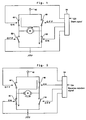
- Fig. 4 is a conceptual diagram of an H-shaped bridge circuit for driving the motor M of the electric screwdriver 12 provided in the power circuit 32.
- M in Fig. 4 represents a DC motor of brush type serving as the screwdriver motor
- 42 designates a positive power source voltage terminal for the direct-current power source
- 44 is a first switch element
- 46 is a second switch element
- 48 is a third switch element
- 50 is a fourth switch element
- 54 is a power circuit controller section.
- the first switch element 44 is connected between the positive power source voltage terminal 42 and one of the terminals of the DC motor M
- the third switch element 48 is connected between the positive power source voltage terminal 42 and the other of the terminals of the DC motor M.
- the fourth switch element 50 is connected between the ground terminal (negative power source voltage terminal) and the one of the terminals of the DC motor M, and the second switch element 46 is connected between the ground terminal and the other of the terminals of the DC motor M.
- Each switch elements 44, 46, 48, 50 is made of, for example, transistor and applied with the ON/OFF control by the power circuit control section 54.
- the power circuit control section 54 upon receipt of the start signal for the normal rotation mode from the first signal line D3, controls the third switch element 48 and the fourth switch element 50 to be OFF and the first switch element 44 and the second switch element 46 to be ON so as to drive the motor M in the direction for normal rotation, as shown in Fig. 4 .
- the power circuit control section 54 when the power circuit control section 54 receives the start signal for the reverse rotation mode (the reverse rotation signal) from the second signal line D4, it controls the first switch element 44 and the second switch element 46 to be OFF and the third switch element 48 and the fourth switch element 50 to be ON so as to drive the motor M in the direction for reverse rotation, as shown in Fig. 5 .
- the power circuit control section 54 upon receipt of the tightening completion signal from the second signal line D4 during its normal rotation, controls the second switch element 46 and the fourth switch element 50 to be OFF and the first switch element 44 and the third switch element 48 to be ON, as shown in Fig. 6 .
- a closed circuit is formed which includes the first switch element 44, the third switch element 48 and the motor M, and the thus formed closed circuit works as the braking short circuit to the motor M to apply braking to the motor M.
- the present invention in order to avoid the problem, provides ON/OFF control or switching control to the first switch element 44 and/or the third switch element 48 (the third switch element 48 in the embodiment of Fig. 6 ).
- the present invention has employed a frequency modulated control method in order to provide this ON/OFF control, as shown in Fig. 7 .
- the first switch element 44 and/or the third switch element 48 are/is controlled to make an ON/OFF action at high frequency (with a constant length of the OFF time period), which is gradually lowered to the ON/OFF action of frequency consistent with the revolution speed.
- the first switch element 44 and/or the third switch element 48 are/is controlled to make the ON/OFF action at high frequency.
- Fig. 8 shows a current flowing through the braking short circuit with no such ON/OFF control applied ( Fig. 8a ) and a current flowing through the braking short circuit with such ON/OFF control applied ( Fig. 8b ) according to the present invention.
- the ON/OFF control is applied according to the present invention, the maximum current value flowing through the short circuit can be suppressed into the order of 4A by applying the short circuit current at a predetermined time interval.
- the present invention has been described with respect to some exemplary embodiments, the present invention is not limited thereto.
- the controller 14 comprises the counter 34 for counting the number of tightened screws in the illustrated embodiment
- the counter may be fitted externally, and in that case the controller is required only to send the tightening completion signal and/or the reverse rotation signal received from the electric screwdriver to the externally fitted counter.
- the starting switch 20 is applied with the reference voltage, it may be applied with the ground potential.
Landscapes
- Engineering & Computer Science (AREA)
- Mechanical Engineering (AREA)
- Power Engineering (AREA)
- Details Of Spanners, Wrenches, And Screw Drivers And Accessories (AREA)
Priority Applications (1)
| Application Number | Priority Date | Filing Date | Title |
|---|---|---|---|
| EP15156359.0A EP2913156B1 (en) | 2004-08-30 | 2005-08-04 | An electric screwdriver and a controller thereof |
Applications Claiming Priority (2)
| Application Number | Priority Date | Filing Date | Title |
|---|---|---|---|
| JP2004250757A JP4203459B2 (ja) | 2004-08-30 | 2004-08-30 | 電動ドライバ装置 |
| PCT/JP2005/014311 WO2006025181A1 (ja) | 2004-08-30 | 2005-08-04 | 電動ドライバ及びその制御装置 |
Related Child Applications (2)
| Application Number | Title | Priority Date | Filing Date |
|---|---|---|---|
| EP15156359.0A Division EP2913156B1 (en) | 2004-08-30 | 2005-08-04 | An electric screwdriver and a controller thereof |
| EP15156359.0A Division-Into EP2913156B1 (en) | 2004-08-30 | 2005-08-04 | An electric screwdriver and a controller thereof |
Publications (3)
| Publication Number | Publication Date |
|---|---|
| EP1800802A1 EP1800802A1 (en) | 2007-06-27 |
| EP1800802A4 EP1800802A4 (en) | 2014-08-20 |
| EP1800802B1 true EP1800802B1 (en) | 2016-06-08 |
Family
ID=35999842
Family Applications (2)
| Application Number | Title | Priority Date | Filing Date |
|---|---|---|---|
| EP05768492.0A Expired - Lifetime EP1800802B1 (en) | 2004-08-30 | 2005-08-04 | Electric driver and controller for the same |
| EP15156359.0A Expired - Lifetime EP2913156B1 (en) | 2004-08-30 | 2005-08-04 | An electric screwdriver and a controller thereof |
Family Applications After (1)
| Application Number | Title | Priority Date | Filing Date |
|---|---|---|---|
| EP15156359.0A Expired - Lifetime EP2913156B1 (en) | 2004-08-30 | 2005-08-04 | An electric screwdriver and a controller thereof |
Country Status (7)
Families Citing this family (44)
| Publication number | Priority date | Publication date | Assignee | Title |
|---|---|---|---|---|
| DE102008030813A1 (de) * | 2007-07-04 | 2009-01-08 | Marquardt Gmbh | Ansteuereinrichtung für einen Elektromotor |
| DE102008040793A1 (de) * | 2008-07-28 | 2010-02-04 | Robert Bosch Gmbh | Motoransteuerschaltung für ein batteriebetriebenes Elektrowerkzeug |
| JP5165547B2 (ja) * | 2008-12-17 | 2013-03-21 | 三洋機工株式会社 | ネジの締付管理システム |
| JP4349641B1 (ja) | 2009-03-23 | 2009-10-21 | 田中電子工業株式会社 | ボールボンディング用被覆銅ワイヤ |
| SE534091C2 (sv) * | 2009-05-20 | 2011-04-26 | Ind Service Applic Isa Ab | Metod och system för att utvärdera spelet mellan två gängade komponenter. |
| CN102085648B (zh) * | 2009-12-03 | 2014-09-10 | 奇力速工业股份有限公司 | 可侦测螺丝是否正确锁固的电动起子 |
| CN102139477A (zh) * | 2010-02-01 | 2011-08-03 | 有限会社井出计器 | 螺钉紧固诊断装置及电动驱动器 |
| JP2011156629A (ja) * | 2010-02-02 | 2011-08-18 | Makita Corp | モータ制御装置、電動工具、及びプログラム |
| DE102010030065A1 (de) | 2010-06-15 | 2011-12-15 | Hilti Aktiengesellschaft | Eintreibvorrichtung |
| DE102010030098A1 (de) | 2010-06-15 | 2011-12-15 | Hilti Aktiengesellschaft | Eintreibvorrichtung |
| DE102010030118A1 (de) * | 2010-06-15 | 2011-12-15 | Hilti Aktiengesellschaft | Eintreibvorrichtung |
| CN102398244A (zh) * | 2010-09-13 | 2012-04-04 | 鸿富锦精密工业(深圳)有限公司 | 螺丝计数器 |
| US9022135B2 (en) * | 2012-10-02 | 2015-05-05 | Stanley Black & Decker, Inc. | Torque-applying tool and torque controller therefor |
| CN103846849A (zh) * | 2012-11-30 | 2014-06-11 | 奇力速工业股份有限公司 | 可侦测螺丝锁固的电动起子 |
| US9395257B2 (en) * | 2013-05-10 | 2016-07-19 | Snap-On Incorporated | Electronic torque tool with integrated real-time clock |
| CN104175267B (zh) * | 2013-05-20 | 2016-08-03 | 南京德朔实业有限公司 | 电动工具及其控制方法 |
| WO2015061370A1 (en) | 2013-10-21 | 2015-04-30 | Milwaukee Electric Tool Corporation | Adapter for power tool devices |
| JP6245943B2 (ja) * | 2013-10-31 | 2017-12-13 | Tone株式会社 | 締付装置 |
| JP6322387B2 (ja) * | 2013-11-05 | 2018-05-09 | Tone株式会社 | 締付装置及び締付方法 |
| WO2015197103A1 (en) | 2014-06-23 | 2015-12-30 | Husqvarna Ab | Failsafe hardware brake mechanism for outdoor power equipment |
| AU2016257438B2 (en) | 2015-05-04 | 2019-03-07 | Milwaukee Electric Tool Corporation | Power tool and method for wireless communication |
| US10603770B2 (en) | 2015-05-04 | 2020-03-31 | Milwaukee Electric Tool Corporation | Adaptive impact blow detection |
| US10295990B2 (en) | 2015-05-18 | 2019-05-21 | Milwaukee Electric Tool Corporation | User interface for tool configuration and data capture |
| CN107921613B (zh) | 2015-06-02 | 2020-11-06 | 米沃奇电动工具公司 | 具有电子离合器的多速电动工具 |
| US10339496B2 (en) | 2015-06-15 | 2019-07-02 | Milwaukee Electric Tool Corporation | Power tool communication system |
| CN107921522B (zh) | 2015-06-15 | 2021-08-17 | 米沃奇电动工具公司 | 液压压接机工具 |
| CN207096983U (zh) | 2015-06-16 | 2018-03-13 | 米沃奇电动工具公司 | 包括电动工具和外部设备的系统、包括外部设备和服务器的系统和服务器 |
| JP2015221494A (ja) * | 2015-09-08 | 2015-12-10 | 日東工器株式会社 | 螺合部材締め付け工具及びカウント装置 |
| US10345797B2 (en) | 2015-09-18 | 2019-07-09 | Milwaukee Electric Tool Corporation | Power tool operation recording and playback |
| EP3369292B1 (en) | 2015-10-30 | 2020-12-02 | Milwaukee Electric Tool Corporation | Remote light control, configuration, and monitoring |
| US11424601B2 (en) | 2015-11-02 | 2022-08-23 | Milwaukee Electric Tool Corporation | Externally configurable worksite power distribution box |
| US10646982B2 (en) | 2015-12-17 | 2020-05-12 | Milwaukee Electric Tool Corporation | System and method for configuring a power tool with an impact mechanism |
| KR102251270B1 (ko) | 2016-01-05 | 2021-05-11 | 밀워키 일렉트릭 툴 코포레이션 | 전동 공구를 위한 진동 감소 시스템 및 그 방법 |
| WO2017136546A1 (en) | 2016-02-03 | 2017-08-10 | Milwaukee Electric Tool Corporation | System and methods for configuring a reciprocating saw |
| PL3419791T3 (pl) | 2016-02-25 | 2022-06-13 | Milwaukee Electric Tool Corporation | Elektronarzędzie z czujnikiem położenia wyjściowego |
| US11622392B2 (en) | 2016-06-06 | 2023-04-04 | Milwaukee Electric Tool Corporation | System and method for establishing a wireless connection between power tool and mobile device |
| TWM555274U (zh) | 2016-06-06 | 2018-02-11 | 米沃奇電子工具公司 | 用以與動力工具裝置作連接的行動裝置 |
| IT201700050638A1 (it) * | 2017-05-10 | 2018-11-10 | St Microelectronics Srl | Procedimento di funzionamento di dispositivi alimentati a radiofrequenza, circuito e dispositivo corrispondenti |
| US11586175B2 (en) * | 2017-12-08 | 2023-02-21 | Connectec Japan Corporation | Tool, task management device, task management method, and task management system |
| IT201800020338A1 (it) * | 2018-12-20 | 2020-06-20 | Atlas Copco Ind Technique Ab | Dispositivo di frenatura posizionabile su banchi di verifica del corretto funzionamento di avvitatori industriali. |
| CN113224994B (zh) * | 2021-04-19 | 2023-03-03 | 惠州拓邦电气技术有限公司 | 一种电动工具扭力调节方法、装置及电动工具 |
| CN115229487A (zh) * | 2022-09-05 | 2022-10-25 | 温州长江汽车电子有限公司 | 一种防止螺钉漏打的系统及方法 |
| CN115741556A (zh) * | 2022-11-18 | 2023-03-07 | 常州泽明自动化设备有限公司 | 电动螺丝刀控制方法、装置、驱动控制器及电动螺丝刀 |
| JP7514439B1 (ja) * | 2023-06-01 | 2024-07-11 | 有限会社井出計器 | 電動ドライバシステムおよびドライバ制御装置 |
Family Cites Families (41)
| Publication number | Priority date | Publication date | Assignee | Title |
|---|---|---|---|---|
| US3536536A (en) * | 1968-07-08 | 1970-10-27 | Eagle Picher Ind Inc | Storage battery system with electrolyte in a separate container |
| DE2926111A1 (de) * | 1979-06-28 | 1981-01-08 | Scintilla Ag | Elektrohandwerkzeug |
| US4307325A (en) * | 1980-01-28 | 1981-12-22 | Black & Decker Inc. | Digital control system for electric motors in power tools and the like |
| JPS6047073B2 (ja) * | 1981-10-23 | 1985-10-19 | 日東精工株式会社 | 自動ねじ締め機 |
| JPS58160063A (ja) * | 1982-03-15 | 1983-09-22 | 日東工器株式会社 | 電動ドライバ− |
| IT1212535B (it) * | 1982-10-26 | 1989-11-30 | Star Utensili Elett | Frizione elettronica a piu' livelli di intervento per utensili elettrici a velocita'selezionabile. |
| DE3536416A1 (de) * | 1984-06-23 | 1987-04-23 | Holland Letz Felo Werkzeug | Steuereinrichtung fuer den einem gleichstrommotor, insbesondere eines werkzeuges, wie eines schraubendrehers oder einer kartuschenpistole zuzufuehrenden strom |
| JPS6150777A (ja) | 1984-08-14 | 1986-03-13 | 株式会社小松製作所 | ボルトの締付け装置 |
| EP0170068B1 (en) | 1984-06-29 | 1991-09-04 | Kabushiki Kaisha Komatsu Seisakusho | Bolt fastening method |
| JPH0677850B2 (ja) | 1985-09-07 | 1994-10-05 | トヨタ自動車株式会社 | ロボツトツ−ルのキヤリブレ−シヨン方法 |
| JPS62157784A (ja) * | 1985-12-27 | 1987-07-13 | 日立工機株式会社 | 電動ドライバ |
| DE3607672A1 (de) * | 1986-03-08 | 1987-09-17 | Holland Letz Felo Werkzeug | Elektromotorischer antrieb fuer einen auf rechts- und linkslauf umschaltbaren handschrauber |
| JPS63318270A (ja) * | 1987-06-20 | 1988-12-27 | 東信電気株式会社 | 締付けトルク値の検査方法 |
| JPS6451275A (en) * | 1987-08-21 | 1989-02-27 | Nitto Seiko Kk | Screw-driving forgetting preventive device for automatic screw driver |
| US5212862A (en) * | 1990-10-09 | 1993-05-25 | Allen-Bradley Company, Inc. | Torque-angle window control for threaded fasteners |
| JPH04176573A (ja) * | 1990-11-08 | 1992-06-24 | Kobe Steel Ltd | ネジ部材の自動締緩方法 |
| US5315501A (en) * | 1992-04-03 | 1994-05-24 | The Stanley Works | Power tool compensator for torque overshoot |
| JP3275923B2 (ja) | 1992-11-02 | 2002-04-22 | セイコーエプソン株式会社 | 電子装置におけるキースイッチ |
| JP3452373B2 (ja) * | 1992-12-18 | 2003-09-29 | 松下電器産業株式会社 | ねじ締め装置、およびねじ締め方法 |
| US5402688A (en) * | 1993-03-17 | 1995-04-04 | Sumitomo Metal Industries, Ltd. | Method and apparatus for determining the tightened condition of a pipe joint |
| US5440215A (en) * | 1993-07-06 | 1995-08-08 | Black & Decker Inc. | Electrical power tool having a motor control circuit for increasing the effective torque output of the power tool |
| JPH0760656A (ja) | 1993-08-30 | 1995-03-07 | Semu Network:Kk | 電気ドライバ−のネジ締付完了の確認方法及びその確認装置 |
| JP2799820B2 (ja) | 1993-09-17 | 1998-09-21 | マルホン工業株式会社 | パチンコ機 |
| GB9320181D0 (en) * | 1993-09-30 | 1993-11-17 | Black & Decker Inc | Improvements in and relating to power tools |
| JPH07164261A (ja) * | 1993-12-10 | 1995-06-27 | Mazda Motor Corp | ボルトの締付異常検出方法および検出装置 |
| JP2936506B2 (ja) * | 1995-07-11 | 1999-08-23 | クワンタイシステムス株式会社 | 最適時間ボルト締付方法 |
| JP4009760B2 (ja) * | 1995-11-24 | 2007-11-21 | 忠弘 大見 | ねじ部材締付方法 |
| US5831402A (en) * | 1996-03-15 | 1998-11-03 | Yang; Tai-Her | Double direction actuating type tool of loose forward and loose backward assisting style |
| US5898598A (en) * | 1996-10-25 | 1999-04-27 | Cooper Technologies Company | System and apparatus for a torque transducer with data processing capabilities |
| US5937370A (en) * | 1997-09-17 | 1999-08-10 | C.E. Electronics, Inc. | Tool monitor and assembly qualifier |
| JP2000047705A (ja) | 1998-07-28 | 2000-02-18 | Hitachi Ltd | 作業指示装置 |
| US6536536B1 (en) * | 1999-04-29 | 2003-03-25 | Stephen F. Gass | Power tools |
| US6655471B2 (en) * | 1999-12-16 | 2003-12-02 | Magna-Lastic Device, Inc. | Impact tool control method and apparatus and impact tool using the same |
| JP2001275374A (ja) * | 2000-03-27 | 2001-10-05 | Brother Ind Ltd | モータ制御装置および記憶媒体 |
| US6567754B1 (en) * | 2001-03-12 | 2003-05-20 | C.E. Electronics, Inc. | Qualifier |
| JP2003123050A (ja) | 2001-10-09 | 2003-04-25 | Sugisaki Keiki Kk | 電気工具の作業回数計数装置 |
| US20030105599A1 (en) * | 2001-11-30 | 2003-06-05 | Fisher Craig Brett | System for ensuring proper completion of tasks |
| JP4093145B2 (ja) * | 2003-08-26 | 2008-06-04 | 松下電工株式会社 | 締付け工具 |
| US6971454B2 (en) * | 2004-03-16 | 2005-12-06 | Bogue Edward M | Pulsed rotation screw removal and insertion device |
| JP4211676B2 (ja) * | 2004-05-12 | 2009-01-21 | パナソニック電工株式会社 | インパクト回転工具 |
| US20060263304A1 (en) * | 2005-05-23 | 2006-11-23 | Halikas James A | Method of controlling alcohol intake and reversing alcohol effects |
-
2004
- 2004-08-30 JP JP2004250757A patent/JP4203459B2/ja not_active Expired - Lifetime
-
2005
- 2005-08-04 EP EP05768492.0A patent/EP1800802B1/en not_active Expired - Lifetime
- 2005-08-04 EP EP15156359.0A patent/EP2913156B1/en not_active Expired - Lifetime
- 2005-08-04 KR KR1020087005792A patent/KR20080028514A/ko not_active Ceased
- 2005-08-04 CN CNB2005800347209A patent/CN100446934C/zh not_active Expired - Lifetime
- 2005-08-04 WO PCT/JP2005/014311 patent/WO2006025181A1/ja active Application Filing
- 2005-08-04 KR KR1020077005051A patent/KR100843530B1/ko not_active Expired - Lifetime
- 2005-08-09 TW TW094126970A patent/TWI281428B/zh active
-
2007
- 2007-02-28 US US11/712,111 patent/US7464769B2/en not_active Expired - Lifetime
-
2008
- 2008-04-16 US US12/104,178 patent/US7588098B2/en not_active Expired - Lifetime
Also Published As
| Publication number | Publication date |
|---|---|
| US7464769B2 (en) | 2008-12-16 |
| KR20080028514A (ko) | 2008-03-31 |
| EP2913156B1 (en) | 2016-12-07 |
| CN101039776A (zh) | 2007-09-19 |
| JP2006062063A (ja) | 2006-03-09 |
| KR100843530B1 (ko) | 2008-07-03 |
| US7588098B2 (en) | 2009-09-15 |
| HK1106475A1 (zh) | 2008-03-14 |
| US20070163357A1 (en) | 2007-07-19 |
| US20080196914A1 (en) | 2008-08-21 |
| KR20070033049A (ko) | 2007-03-23 |
| TW200618950A (en) | 2006-06-16 |
| TWI281428B (en) | 2007-05-21 |
| EP1800802A1 (en) | 2007-06-27 |
| JP4203459B2 (ja) | 2009-01-07 |
| EP1800802A4 (en) | 2014-08-20 |
| CN100446934C (zh) | 2008-12-31 |
| WO2006025181A1 (ja) | 2006-03-09 |
| EP2913156A1 (en) | 2015-09-02 |
Similar Documents
| Publication | Publication Date | Title |
|---|---|---|
| EP1800802B1 (en) | Electric driver and controller for the same | |
| US11161227B2 (en) | Electric working machine and method for controlling motor of electric working machine | |
| KR100376990B1 (ko) | 토크제어식 임펙트렌치 | |
| EP0811466B1 (en) | Improvements in or relating to power tools | |
| KR100496658B1 (ko) | 조립 검증 기능의 카운터를 구비한 전동 드라이버 시스템 | |
| JPH0775974A (ja) | 実効トルク出力を増加させるモータ制御回路を具えた電動工具 | |
| TW201406506A (zh) | 衝擊式電動工具之衝擊作動控制方法及其裝置 | |
| JP2008213085A (ja) | 電動工具制御システム | |
| WO2020008666A1 (ja) | 電動工具およびその制御方法、制御プログラム | |
| JP2006062065A (ja) | 電動回転工具のねじ締め制御方法および装置 | |
| JP3883863B2 (ja) | 電池式電動工具及び電池式電動工具の電池残容量検出方法 | |
| JPH10180643A (ja) | 回転打撃工具 | |
| JP4828584B2 (ja) | 電動ドライバ制御装置及び電動ドライバ装置 | |
| JP2024043261A (ja) | 電動工具、および電動工具におけるモータの制御方法 | |
| JP4132161B2 (ja) | 電動工具 | |
| KR20200041555A (ko) | 치과용 핸드피스의 모터 제어 방법 및 장치 | |
| EP0271902A2 (en) | Method of and apparatus for tightening screw-threaded fasteners | |
| JPH07106548B2 (ja) | 滑り検出機能を備えた電動ドライバ | |
| JPH09183072A (ja) | ボルト締結機 | |
| JP3249336U (ja) | 電動回転工具の電動モータ駆動制御システム | |
| JP6621013B2 (ja) | ねじ締め状態の良否判定方法およびシステム | |
| HK1106475B (en) | Electric driver and controller for the same | |
| JPH09309077A (ja) | 電動工具 | |
| JP2001030123A (ja) | 自動ねじ締め機 | |
| JP2001251876A (ja) | モータ制御装置 |
Legal Events
| Date | Code | Title | Description |
|---|---|---|---|
| PUAI | Public reference made under article 153(3) epc to a published international application that has entered the european phase |
Free format text: ORIGINAL CODE: 0009012 |
|
| 17P | Request for examination filed |
Effective date: 20070328 |
|
| AK | Designated contracting states |
Kind code of ref document: A1 Designated state(s): DE FR |
|
| DAX | Request for extension of the european patent (deleted) | ||
| RBV | Designated contracting states (corrected) |
Designated state(s): DE FR |
|
| A4 | Supplementary search report drawn up and despatched |
Effective date: 20140723 |
|
| RIC1 | Information provided on ipc code assigned before grant |
Ipc: B25B 23/14 20060101AFI20140717BHEP |
|
| 17Q | First examination report despatched |
Effective date: 20150619 |
|
| GRAP | Despatch of communication of intention to grant a patent |
Free format text: ORIGINAL CODE: EPIDOSNIGR1 |
|
| INTG | Intention to grant announced |
Effective date: 20151218 |
|
| RIN1 | Information on inventor provided before grant (corrected) |
Inventor name: NAKAZAWA, HIROYUKI NITTO KOHKI CO., LTD. Inventor name: FUJITA, HIDEKI NITTO KOHKI CO., LTD. |
|
| GRAS | Grant fee paid |
Free format text: ORIGINAL CODE: EPIDOSNIGR3 |
|
| GRAA | (expected) grant |
Free format text: ORIGINAL CODE: 0009210 |
|
| AK | Designated contracting states |
Kind code of ref document: B1 Designated state(s): DE FR |
|
| REG | Reference to a national code |
Ref country code: DE Ref legal event code: R096 Ref document number: 602005049500 Country of ref document: DE |
|
| REG | Reference to a national code |
Ref country code: FR Ref legal event code: PLFP Year of fee payment: 12 |
|
| REG | Reference to a national code |
Ref country code: DE Ref legal event code: R097 Ref document number: 602005049500 Country of ref document: DE |
|
| PLBE | No opposition filed within time limit |
Free format text: ORIGINAL CODE: 0009261 |
|
| STAA | Information on the status of an ep patent application or granted ep patent |
Free format text: STATUS: NO OPPOSITION FILED WITHIN TIME LIMIT |
|
| 26N | No opposition filed |
Effective date: 20170309 |
|
| REG | Reference to a national code |
Ref country code: FR Ref legal event code: PLFP Year of fee payment: 13 |
|
| REG | Reference to a national code |
Ref country code: FR Ref legal event code: PLFP Year of fee payment: 14 |
|
| PGFP | Annual fee paid to national office [announced via postgrant information from national office to epo] |
Ref country code: DE Payment date: 20240821 Year of fee payment: 20 |
|
| PGFP | Annual fee paid to national office [announced via postgrant information from national office to epo] |
Ref country code: FR Payment date: 20240828 Year of fee payment: 20 |
|
| REG | Reference to a national code |
Ref country code: DE Ref legal event code: R071 Ref document number: 602005049500 Country of ref document: DE |