EP2913156B1 - An electric screwdriver and a controller thereof - Google Patents
An electric screwdriver and a controller thereof Download PDFInfo
- Publication number
- EP2913156B1 EP2913156B1 EP15156359.0A EP15156359A EP2913156B1 EP 2913156 B1 EP2913156 B1 EP 2913156B1 EP 15156359 A EP15156359 A EP 15156359A EP 2913156 B1 EP2913156 B1 EP 2913156B1
- Authority
- EP
- European Patent Office
- Prior art keywords
- time
- tightening
- tightening operation
- electric screwdriver
- torque
- Prior art date
- Legal status (The legal status is an assumption and is not a legal conclusion. Google has not performed a legal analysis and makes no representation as to the accuracy of the status listed.)
- Active
Links
- 238000012545 processing Methods 0.000 claims description 9
- 230000004044 response Effects 0.000 claims description 8
- 238000012544 monitoring process Methods 0.000 claims description 6
- 238000000034 method Methods 0.000 description 12
- 101001068136 Homo sapiens Hepatitis A virus cellular receptor 1 Proteins 0.000 description 10
- 101000831286 Homo sapiens Protein timeless homolog Proteins 0.000 description 10
- 101000752245 Homo sapiens Rho guanine nucleotide exchange factor 5 Proteins 0.000 description 10
- 102100021688 Rho guanine nucleotide exchange factor 5 Human genes 0.000 description 10
- 238000010586 diagram Methods 0.000 description 9
- 238000012360 testing method Methods 0.000 description 9
- 230000009471 action Effects 0.000 description 7
- 101150074789 Timd2 gene Proteins 0.000 description 5
- 230000008569 process Effects 0.000 description 3
- 230000003213 activating effect Effects 0.000 description 1
- 230000004913 activation Effects 0.000 description 1
- 230000008901 benefit Effects 0.000 description 1
- 230000015572 biosynthetic process Effects 0.000 description 1
- 230000003247 decreasing effect Effects 0.000 description 1
- 230000001419 dependent effect Effects 0.000 description 1
- 230000000694 effects Effects 0.000 description 1
- 238000005259 measurement Methods 0.000 description 1
- 230000004048 modification Effects 0.000 description 1
- 238000012986 modification Methods 0.000 description 1
- 238000007619 statistical method Methods 0.000 description 1
Images


Classifications
-
- B—PERFORMING OPERATIONS; TRANSPORTING
- B25—HAND TOOLS; PORTABLE POWER-DRIVEN TOOLS; MANIPULATORS
- B25B—TOOLS OR BENCH DEVICES NOT OTHERWISE PROVIDED FOR, FOR FASTENING, CONNECTING, DISENGAGING OR HOLDING
- B25B23/00—Details of, or accessories for, spanners, wrenches, screwdrivers
- B25B23/14—Arrangement of torque limiters or torque indicators in wrenches or screwdrivers
-
- H—ELECTRICITY
- H02—GENERATION; CONVERSION OR DISTRIBUTION OF ELECTRIC POWER
- H02P—CONTROL OR REGULATION OF ELECTRIC MOTORS, ELECTRIC GENERATORS OR DYNAMO-ELECTRIC CONVERTERS; CONTROLLING TRANSFORMERS, REACTORS OR CHOKE COILS
- H02P7/00—Arrangements for regulating or controlling the speed or torque of electric DC motors
- H02P7/06—Arrangements for regulating or controlling the speed or torque of electric DC motors for regulating or controlling an individual dc dynamo-electric motor by varying field or armature current
- H02P7/18—Arrangements for regulating or controlling the speed or torque of electric DC motors for regulating or controlling an individual dc dynamo-electric motor by varying field or armature current by master control with auxiliary power
- H02P7/24—Arrangements for regulating or controlling the speed or torque of electric DC motors for regulating or controlling an individual dc dynamo-electric motor by varying field or armature current by master control with auxiliary power using discharge tubes or semiconductor devices
- H02P7/28—Arrangements for regulating or controlling the speed or torque of electric DC motors for regulating or controlling an individual dc dynamo-electric motor by varying field or armature current by master control with auxiliary power using discharge tubes or semiconductor devices using semiconductor devices
- H02P7/285—Arrangements for regulating or controlling the speed or torque of electric DC motors for regulating or controlling an individual dc dynamo-electric motor by varying field or armature current by master control with auxiliary power using discharge tubes or semiconductor devices using semiconductor devices controlling armature supply only
- H02P7/29—Arrangements for regulating or controlling the speed or torque of electric DC motors for regulating or controlling an individual dc dynamo-electric motor by varying field or armature current by master control with auxiliary power using discharge tubes or semiconductor devices using semiconductor devices controlling armature supply only using pulse modulation
-
- B—PERFORMING OPERATIONS; TRANSPORTING
- B25—HAND TOOLS; PORTABLE POWER-DRIVEN TOOLS; MANIPULATORS
- B25B—TOOLS OR BENCH DEVICES NOT OTHERWISE PROVIDED FOR, FOR FASTENING, CONNECTING, DISENGAGING OR HOLDING
- B25B21/00—Portable power-driven screw or nut setting or loosening tools; Attachments for drilling apparatus serving the same purpose
-
- B—PERFORMING OPERATIONS; TRANSPORTING
- B25—HAND TOOLS; PORTABLE POWER-DRIVEN TOOLS; MANIPULATORS
- B25B—TOOLS OR BENCH DEVICES NOT OTHERWISE PROVIDED FOR, FOR FASTENING, CONNECTING, DISENGAGING OR HOLDING
- B25B23/00—Details of, or accessories for, spanners, wrenches, screwdrivers
-
- B—PERFORMING OPERATIONS; TRANSPORTING
- B25—HAND TOOLS; PORTABLE POWER-DRIVEN TOOLS; MANIPULATORS
- B25B—TOOLS OR BENCH DEVICES NOT OTHERWISE PROVIDED FOR, FOR FASTENING, CONNECTING, DISENGAGING OR HOLDING
- B25B23/00—Details of, or accessories for, spanners, wrenches, screwdrivers
- B25B23/14—Arrangement of torque limiters or torque indicators in wrenches or screwdrivers
- B25B23/147—Arrangement of torque limiters or torque indicators in wrenches or screwdrivers specially adapted for electrically operated wrenches or screwdrivers
-
- H—ELECTRICITY
- H02—GENERATION; CONVERSION OR DISTRIBUTION OF ELECTRIC POWER
- H02P—CONTROL OR REGULATION OF ELECTRIC MOTORS, ELECTRIC GENERATORS OR DYNAMO-ELECTRIC CONVERTERS; CONTROLLING TRANSFORMERS, REACTORS OR CHOKE COILS
- H02P7/00—Arrangements for regulating or controlling the speed or torque of electric DC motors
- H02P7/03—Arrangements for regulating or controlling the speed or torque of electric DC motors for controlling the direction of rotation of DC motors
- H02P7/04—Arrangements for regulating or controlling the speed or torque of electric DC motors for controlling the direction of rotation of DC motors by means of a H-bridge circuit
Definitions
- the present invention relates to an electric screwdriver controller.
- JP S58 71079 A discloses an automatic screwdriver, which uses a statistical method, which needs a number of trial fastening operations to determine a time for complete thread fastening.
- JP H09-29655 A discloses tool and a method for operating the same. The method includes a procedure for setting a switch to set a fastening start speed, target torque and allowable error based on characteristics of a nut runner.
- JP S63-318270 A discloses a method of inspecting clamping torque of a torque wrench.
- a typical (in most cases, minimal) tightening time expected in the normal tightening operation is previously set as a reference time in the controller, such that if the signal indicating the completion of the tightening is generated by the electric screwdriver in a shorter time than the reference time, then the controller can determine that the screw must have been tightened in the inclined state or a once tightened screw has been tightened again (for additional tightening).
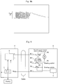
- Fig. 9 shows a typical wiring diagram in an electric screwdriver D comprising a controller P with a function for preventing any screws from being left not tightened.
- "D1" and “D2" designate power source lines to a screwdriver motor M
- "D3" is an start/stop signal line
- "D4" is a tightening completion signal line
- "D5" is a common line.
- the common line is connected to a reference voltage Vs.
- the power source lines D1 and D2 are connected to a power supply circuit S of the controller P.
- the screwdriver motor M is a type of direct-current motor and the power circuit S comprises a direct-current power source.
- RS designates a normal/reverse rotation select switch for changing the polarity of the power source output voltage in order to select the rotation direction of the motor M (normal or reverse rotation).
- SS designates a starting switch, which in response to an open/close operation by an operator, sends a start/stop signal to the power circuit S via the start/stop signal line D3. For example, when the starting switch SS is closed, the reference voltage Vs from the common line D5 is applied to the power circuit S as the start signal, whereas when the starting switch is opened, the reference voltage Vs from the common line D5 is shut off, and the stop signal is sent to the power supply circuit by the shut-off.
- BS designates a braking switch of a normally open type, which is shifted to a closed position by an action of a cam C incorporated in the screwdriver when the load torque in the tightening operation has reached a predetermined value.
- Vs a tightening completion signal at the reference voltage Vs is sent to a counter T for counting the number of tightened screws and also to the power supply circuit S in the controller P via the tightening completion signal line D4.
- the circuit shown in Fig. 9 is not able to provide the signal from the electric driver D to the controller P to reverse the count in the counter T in a micro computer A for counting the number of the tightened screws when the user drives the electric screwdriver D in reverse direction to untighten the screw that has been tightened incorrectly as discussed above.
- the circuit configuration of the electric screwdriver D is modified as such as shown in Fig. 10 .
- the normal/reverse rotation selection switch RS is moved from the motor power source lines D1 and D2 to signal line D5 and replaced by an ON/OFF switch, wherein the power source circuit in the controller P may be provided with normal/reverse changing function.
- the normal/reverse rotation selection switch RS may be turned to ON position (closed state), for example, so as to send a signal (ON signal) of the reference voltage Vs from the common line D6 to the power supply circuit S in the controller P through the signal line D5 as a reverse rotation control signal, and to cause the power supply circuit S to invert the polarity of the output voltage (motor driving voltage), while at the same time sending the same ON signal to the counter T to reverse the count back.
- an electric screwdriver controller as set forth in claim 1 is provided. Further embodiments of the invention are inter alia disclosed in the dependent claims.
- an electric screwdriver controller having a function for determining that a correct tightening operation has been carried out when said tightening operation has taken a time longer than a reference time
- said controller inter alia comprising:
- an electric screwdriver controller may comprise:
- the present invention allows for the expected time of tightening (reference time) to be taken as a reference for determining whether or not the tightening operation has been successfully completed to be determined automatically by simply conducting a tightening test for a certain number of screws rather than by using a stopwatch as practiced conventionally, and thus determined expected time can be set in the controller.
- an electric screwdriver device 10 comprises an electric screwdriver 12 and a screwdriver controller 14 connected to the electric screwdriver via a cable 13 and having a function for preventing any screws from being left not tightened.
- the electric screwdriver 12 has an electric circuit (electric screwdriver circuit) as shown in Fig. 2 in association with the function for preventing any screws from being left not tightened.
- the illustrated electric screwdriver circuit is intended to solve the problems in conjunction with the prior art as set forth above with reference to Figs. 9 and 10 .
- the circuit comprises power source lines D1 and D2 for supplying a drive voltage to a screwdriver motor M, a first and a second signal lines D3 and D4 for sending an appropriate signal from the electric screwdriver 12 to the controller 14, and a common line D5 for generating an appropriate signal onto the first and the second signal lines D3 and D4.
- the common line D5 is connected to a reference voltage Vs.
- the starting switch 20 is an ON/OFF switch intended to send a start/stop signal in response to the manual operation by the operator to the controller 14. If the starting switch 20 is closed (ON) under the condition where the normal rotation/reverse-rotation shifting switch 28 is in the normal rotation connecting position as illustrated, the signal (ON signal) at the reference voltage Vs from the common line D5 is sent from the starting switch 20 to the first signal line D3 via the movable contact 28f and the fixed contacts 28d and 28a of the normal rotation/reverse-rotation shifting switch 28, and through the first signal line D3, the signal is passed to a power circuit 32 of the controller 14 as the start signal. A microcomputer 40 in the controller 14 is shifted to the normal rotation mode in response to a receipt of the start signal through the first signal line D3. If the starting switch 20 is shifted to an open state (OFF), the signal at the reference voltage Vs from the common line D5 is shut off, and this is given as the stop signal to the power circuit 32 of the controller 14.
- the starting switch is turned into the closed state (ON) under the condition where the normal rotation/reverse-rotation shifting switch 28 is in the reverse rotation connecting position
- the signal (ON signal) at the reference voltage Vs from the common line D5 is sent from the starting switch 20 to the second signal line D4 via the movable contact 28f and the fixed contact 28b of the normal rotation/reverse-rotation shifting switch 28, and through the second signal line D4, the signal is passed to the power circuit 32 of the controller 14 as the start signal (i.e., the reverse rotation signal).
- the microcomputer 40 of the controller 14 is shifted to the reverse rotation mode in response to the receipt of the same ON signal through the second signal line D4, and a counter for counting the number of tightened screws in the microcomputer 40 now in this mode carries out the reverse counting by decreasing the count value by one. Furthermore, in the reverse rotation mode, as is the case with the normal rotation mode, if the starting switch 20 is shifted to the open state (OFF), the ON signal at the reference voltage Vs from the common line D5 is shut off thereby providing the stop signal to the power circuit 32 of the controller 14.
- the braking switch 26 is a normal-open type switch and adapted to be shifted to the closed state by a cam 29 incorporated in the screwdriver 12, which is activated when the load torque in the tightening operation has reached a predetermined value.
- the braking switch 26 is closed, the tightening completion signal is sent from the screwdriver 12 to the controller 14.
- the signal at the reference voltage Vs from the common line D5 is sent from the braking switch 26 to the second signal line D4 via the movable contact 28e and the fixed contacts 28c and 28b of the normal rotation/reverse-rotation shifting switch 28 as the tightening completion signal and through the second signal line D4, the signal is sent to the screwdriver controller 14.
- the power circuit 32 is activated in response to the tightening completion signal from the second signal line D4 to shut down the output of the motor driving voltage and to make a short circuit of the power source lines D1 and D2 to apply the braking action to the screwdriver motor M.
- the counter 34 for counting the number of tightened screws in the microcomputer 40 is caused to increase the count value by one.
- Fig. 2 shows the configuration in which the start signal, the stop signal and the tightening completion signal are to be supplied directly from the respective signal lines to the power circuit 32 within the screwdriver controller 14, another configuration may be contemplated, in which the microcomputer 40 once receives all of the signals from the electric screwdriver 12 so as to control the power circuit 32.
- start signal reference voltage Vs
- motor driving voltage having the polarity for the normal rotation
- the braking switch 26 is closed by the cam 29 (which is activated by the rotationally driven shaft of the electric screwdriver), and the tightening completion signal is sent to the power circuit 32 and the microcomputer 40 (and thus to the counter 34 for counting the number of tightened screws) within the screwdriver control device 14.
- any required actions such as stopping or shutting off of the output of the motor driving voltage, is carried out, while in the counter 34, the counting is carried out under the assumption that one of the screws has been tightened.
- the counting result i.e., the count value or the accumulated number of screws that have been tightened
- the operator may shift the normal rotation/reverse-rotation shifting switch 28 to the reverse-rotation connecting position so as to close the starting switch 20 and thus to cause the starting signal (i.e., the reverse rotation signal) to be sent via the second signal line D4 and thereby cause the power circuit 32 of the controller 14 to invert the output polarity, which in turn drives the motor M in the direction for reverse rotation to turn the screw, that has been once tightened, in the loosening direction for removing the screw.
- the reverse rotation signal is sent to the counter 34, where the count is reversed to modify the counting of the number of tightened screws.
- the electric screwdriver allows the counter for counting the number of tightened screws in the controller to have a function for reversing the count in association with the reverse rotation of the electric screwdriver without increasing a number of signal lines from the electric screwdriver to the controllers.
- circuit wiring of the electric screwdriver illustrated in Fig. 2 has been developed in order to solve problems (which will be discussed below) found in the circuit wiring as shown in Fig. 11 , which had been initially developed by the inventor of the present invention to solve the problems as pointed out with reference to Figs. 9 and 10 .
- the electric screwdriver has power source lines D1 and D2 for the screwdriver motor M, the first and the second signal lines D3 and D4, and the common line D5, like the one as shown in Fig. 2 .
- the common line D5 is fixed at the reference voltage Vs (e.g., 0 volt).
- this electric wiring has the normal rotation/reverse-rotation shifting switch 28.
- the normal rotation/reverse-rotation shifting switch 28 includes the fixed contacts 28a, 28b, 28c and 28d, and the movable contacts 28e and 28f.
- the fixed contact 28b is connected to the fixed contact 28c.
- the movable contact 28f is connected to the common line D5 via the starting switch 20, while the movable contact 28e is connected to the common line D5 via the braking switch 26.
- the normal rotation/reverse-rotation shifting switch 28 is adapted to be shift between the normal rotation connecting position ( Fig. 11 ) where the movable contacts 28e and 28f are connected to the fixed contacts 28a and 28c respectively and the reverse rotation connecting position (not shown) where the movable contacts 28e and 28f are connected to the fixed contacts 28b and 28d respectively.
- Respective actions in the controller 14 including the activation, the reverse rotation, the normal counting and reverse counting of the number of tightened screws and so on based on the operations of the starting switch 20, the braking switch 26 and the normal rotation/reverse-rotation shifting switch 28 are carried out in a similar manner to that in the circuit shown in Fig. 2 .
- the CPU in the microcomputer of the controller 14 determines that in a subsequent program cycle, the normal rotation or reverse rotation has been set by the rotation/reverse-rotation switch and the starting switch has been turned on, thereby activating the screwdriver in spite of the fact that the starting switch is actually not turned on.
- the circuit wiring of Fig. 2 even if the braking switch is in such a condition as described above, the starting switch arranged in series with the braking switch is held in the OFF position, and thus no problem will occur.
- a reference value is determined in order to enable the determination whether or not the screw has been tightened correctly without being inclined.
- a tightening operation time is used as a reference to make the determination whether or not the tightening operation has been carried out correctly without causing the screw to be inclined or out of upright. This takes advantage of the fact that if the screw has been tightened out of upright, the tightening torque is increased more rapidly than that in the normal tightening operation to generate the tightening completion signal earlier.
- the tightening operation test is carried out for the predetermined number of screws prior to the actual tightening operation without requesting the operator to conduct a cumbersome process, wherein the time consumed for each correct tightening operation is measured and the minimal value is taken as the reference value for the tightening operation time.
- the microcomputer 40 in the controller 14 determines the reference value of the tightening operation time based on the tightening completion signal and the like from the electric screwdriver in this tightening operation test in a manner as will be described below.
- Fig. 3 is a flow chart illustrating a procedure by the microcomputer 40 to determine the reference value for the tightening operation time according to the present invention.
- step S3 a timer processing or time measuring operation for each arbitrarily preset time block (50 msec in the illustrated embodiment) is started (step S3), and this timer processing is carried out repeatedly for every time block until the tightening completion signal is received from the second signal line D4 or until the load torque has reached the predetermined value for the tightening completion (step S4), wherein at each timer processing, the tightening operation time TIM2 is incremented by one time block (50 msec in the illustrated embodiment) (step S5).
- step S4 the process further determines whether or not the tightening operation time TIM2 is larger than the previously set expected time TIM1 (step S6), wherein if the tightening operation time TIM2 is smaller than the expected time TIM1, the expected time TIM1 is replaced by the tightening operation time TIM2 which is treated as a new expected time TIM1, or the TIM1 is renewed (step S7). Further, the number of tested screws "m" is incremented by one (step S8).
- M in Fig. 4 represents a DC motor of brush type serving as the screwdriver motor
- 42 designates a positive power source voltage terminal for the direct-current power source
- 44 is a first switch element
- 46 is a second switch element
- 48 is a third switch element
- 50 is a fourth switch element
- 54 is a power circuit controller section.
- the first switch element 44 is connected between the positive power source voltage terminal 42 and one of the terminals of the DC motor M
- the third switch element 48 is connected between the positive power source voltage terminal 42 and the other of the terminals of the DC motor M.
- the power circuit control section 54 upon receipt of the start signal for the normal rotation mode from the first signal line D3, controls the third switch element 48 and the fourth switch element 50 to be OFF and the first switch element 44 and the second switch element 46 to be ON so as to drive the motor M in the direction for normal rotation, as shown in Fig. 4 .
- the power circuit control section 54 when the power circuit control section 54 receives the start signal for the reverse rotation mode (the reverse rotation signal) from the second signal line D4, it controls the first switch element 44 and the second switch element 46 to be OFF and the third switch element 48 and the fourth switch element 50 to be ON so as to drive the motor M in the direction for reverse rotation, as shown in Fig. 5 .
- the power circuit control section 54 upon receipt of the tightening completion signal from the second signal line D4 during its normal rotation, controls the second switch element 46 and the fourth switch element 50 to be OFF and the first switch element 44 and the third switch element 48 to be ON, as shown in Fig. 6 .
- a closed circuit is formed which includes the first switch element 44, the third switch element 48 and the motor M, and the thus formed closed circuit works as the braking short circuit to the motor M to apply braking to the motor M.
- the control circuit in order to avoid the problem, provides ON/OFF control or switching control to the first switch element 44 and/or the third switch element 48 (the third switch element 48 in the embodiment of Fig. 6 ).
- a frequency modulated control method is employed in order to provide this ON/OFF control, as shown in Fig. 7 .
- the first switch element 44 and/or the third switch element 48 are/is controlled to make an ON/OFF action at high frequency (with a constant length of the OFF time period), which is gradually lowered to the ON/OFF action of frequency consistent with the revolution speed.
- the first switch element 44 and/or the third switch element 48 are/is controlled to make the ON/OFF action at high frequency. Since the OFF time period is kept constant, the time period for which the first switch element 44 and/or the third switch element 48 are/is kept ON is relatively made shorter, and consequently the increase in the current flowing through the circuit can be reduced.
- the first switch element 44 and/or the third switch element 48 are/is turned ON/OFF at lower frequency.
- the frequency is defined in four different levels as shown in Fig. 7 , a stepless modulation may be also applicable.
- Fig. 8 shows a current flowing through the braking short circuit with no such ON/OFF control applied ( Fig. 8a ) and a current flowing through the braking short circuit with such ON/OFF control applied ( Fig. 8b ).
- the ON/OFF control is applied the maximum current value flowing through the short circuit can be suppressed into the order of 4A by applying the short circuit current at a predetermined time interval.
- the present invention has been described with respect to some exemplary embodiments, the present invention is not limited thereto.
- the controller 14 comprises the counter 34 for counting the number of tightened screws in the illustrated embodiment
- the counter may be fitted externally, and in that case the controller is required only to send the tightening completion signal and/or the reverse rotation signal received from the electric screwdriver to the externally fitted counter.
- the starting switch 20 is applied with the reference voltage, it may be applied with the ground potential.
Description
- The present invention relates to an electric screwdriver controller.
- There has been provided one type of electric screwdriver equipped with a controller having a function for preventing any screws from being left not tightened. The electric screwdriver, in this type, is connected to the controller, so that when a tightening torque has reached a value equal to or greater than a predetermined value in a tightening operation, a signal indicating the completion of screw-tightening is sent from the electric screwdriver to the controller, and then the controller causes a specific counter (a counter for counting a number of screws tightened) to increment by one to provide a count indication of the number of tightened screws or inform a situation that the number of tightened screws has reached a predetermined one, as for example disclosed in
JP 2000-47705 A JP H7-80128 A JP 2003-123050 A
JP S58 71079 A JP H09-29655 A JP S63-318270 A - In the tightening operation using the electric screwdriver, however, there might be an event that a screw has been tightened out of upright. If a screw is tightened out of upright, typically the tightening torque could reach the predetermined value in a shorter time than in a tightening operation normally carried out. Also, when the screw that has been once tightened is tightened again (for additional thightening), the tightening torque could reach the predetermined value in a shorter time than in a tightening operation normally carried out. Due to this fact, a typical (in most cases, minimal) tightening time expected in the normal tightening operation is previously set as a reference time in the controller, such that if the signal indicating the completion of the tightening is generated by the electric screwdriver in a shorter time than the reference time, then the controller can determine that the screw must have been tightened in the inclined state or a once tightened screw has been tightened again (for additional tightening).
- To determine the aforementioned reference time, it is conventional that a test of tightening is carried out on a certain number of screws prior to a practical tightening operation, in which a time consumed for properly operating screw-tightening is measured by using, for example, a stopwatch, and specifically a shortest time in the time measurements is taken as the reference time. Such a tightening test is, however, a highly cumbersome work for a user.
- There is another possible event in the practical operation, a screw might be tightened at an incorrect location, and in that case, an operation (manipulation) for inversely turning the electric screwdriver is carried out to untighten the screw. In such a case, in response to the operation for inversely turning the electric screwdriver, a counter for counting a number of tightened screws is needed to be reset so as to cancel the count in the incorrect tightening operation. Regarding this point, a device according to the prior art has following problems.
-
Fig. 9 shows a typical wiring diagram in an electric screwdriver D comprising a controller P with a function for preventing any screws from being left not tightened. In the drawing, "D1" and "D2" designate power source lines to a screwdriver motor M, "D3" is an start/stop signal line, "D4" is a tightening completion signal line and "D5" is a common line. The common line is connected to a reference voltage Vs. The power source lines D1 and D2 are connected to a power supply circuit S of the controller P. The screwdriver motor M is a type of direct-current motor and the power circuit S comprises a direct-current power source. "RS" designates a normal/reverse rotation select switch for changing the polarity of the power source output voltage in order to select the rotation direction of the motor M (normal or reverse rotation). "SS" designates a starting switch, which in response to an open/close operation by an operator, sends a start/stop signal to the power circuit S via the start/stop signal line D3. For example, when the starting switch SS is closed, the reference voltage Vs from the common line D5 is applied to the power circuit S as the start signal, whereas when the starting switch is opened, the reference voltage Vs from the common line D5 is shut off, and the stop signal is sent to the power supply circuit by the shut-off. "BS" designates a braking switch of a normally open type, which is shifted to a closed position by an action of a cam C incorporated in the screwdriver when the load torque in the tightening operation has reached a predetermined value. When the braking switch BS is closed, a tightening completion signal at the reference voltage Vs is sent to a counter T for counting the number of tightened screws and also to the power supply circuit S in the controller P via the tightening completion signal line D4. - The circuit shown in
Fig. 9 is not able to provide the signal from the electric driver D to the controller P to reverse the count in the counter T in a micro computer A for counting the number of the tightened screws when the user drives the electric screwdriver D in reverse direction to untighten the screw that has been tightened incorrectly as discussed above. To address this, it may be contemplated that the circuit configuration of the electric screwdriver D is modified as such as shown inFig. 10 .
Specifically, the normal/reverse rotation selection switch RS is moved from the motor power source lines D1 and D2 to signal line D5 and replaced by an ON/OFF switch, wherein the power source circuit in the controller P may be provided with normal/reverse changing function. In this modification, to cause the electric screwdriver D to rotate in reverse direction, the normal/reverse rotation selection switch RS may be turned to ON position (closed state), for example, so as to send a signal (ON signal) of the reference voltage Vs from the common line D6 to the power supply circuit S in the controller P through the signal line D5 as a reverse rotation control signal, and to cause the power supply circuit S to invert the polarity of the output voltage (motor driving voltage), while at the same time sending the same ON signal to the counter T to reverse the count back. - However, such a configuration would lead to some disadvantages, including a problem of cost increase in association with the increased number of signal lines in the electric screwdriver and another problem of no compatibility that an existing electric screwdriver is no more applicable to the controller having been modified as such as described above.
- In accordance with the present invention, an electric screwdriver controller as set forth in
claim 1 is provided. Further embodiments of the invention are inter alia disclosed in the dependent claims. - Specifically, an electric screwdriver controller having a function for determining that a correct tightening operation has been carried out when said tightening operation has taken a time longer than a reference time is disclosed, said controller inter alia comprising:
- a torque monitoring means for monitoring whether or not a load torque in carrying out a tightening operation by using an electric screwdriver has reached a tightening completion torque indicating the completion of the tightening operation;
- a timer means for measuring a time interval from a starting time of the tightening operation to a time when the tightening torque has reached the tightening completion torque, as a tightening operation time; and
- a means for determining a reference time for a subsequent tightening operation based on a plurality of tightening operation time obtained from said timer means in the tightening operations carried out for a predetermined number of screws;
- an expected time setting means for setting an expected time from the starting time to the completion time of the tightening operation;
- a comparing means for comparing the tightening operation time obtained from said timer means to said expected time for each of the tightening operations; and
- an expected time renewing means operable, when a comparison result indicating that the tightening operation time is not longer than the expected time is given by said comparing means, to renew said expected time by replacing said expected time with said tightening operation time, wherein
- the expected time obtained from the expected time renewing means at the time of completion of the tightening operations for a predetermined number of screws is taken as the reference time.
- More specifically, an electric screwdriver controller according to the present invention may comprise:
- a time block setting means for setting a predetermined time period as a time block;
- a tightening completion torque setting means for setting a tightening completion torque; and
- a clock initialization means for initializing said timer means,
- a time block processing means for starting a time block processing in response to a starting of driving operation of said electric screwdriver, and
- a time block addition means for performing a time block processing again by adding by one time block at each time when the period for one time block has elapsed as long as said torque monitoring means determines that said tightening torque has not yet been reached said tightening completion torque.
- The present invention allows for the expected time of tightening (reference time) to be taken as a reference for determining whether or not the tightening operation has been successfully completed to be determined automatically by simply conducting a tightening test for a certain number of screws rather than by using a stopwatch as practiced conventionally, and thus determined expected time can be set in the controller.
-
-
Fig. 1 is a schematic view of an electric screwdriver device; -
Fig. 2 is an electric diagram of the same device; -
Fig. 3 is a flow chart illustrating a procedure for determining an expected time (reference time) for the completion of the tightening operation to be carried out in the same device; -
Fig. 4 is a circuit diagram in a normal rotation mode of a screwdriver motor in the same device; -
Fig. 5 is a circuit diagram in a reverse rotation mode of the same screwdriver motor; -
Fig. 6 is a circuit diagram in a tightening completion mode in the same screwdriver motor; -
Fig. 7 shows an example of an ON/OFF signal used in an ON/OFF control to a braking short circuit to be formed in the tightening completion mode as shown inFig. 6 ; -
Fig. 8a plots a current value flowing through the braking short circuit for the case of no ON/OFF control provided to the short braking circuit; -
Fig. 8b plots the current value flowing through the braking short circuit for the case of ON/OFF control provided to the braking short circuit; -
Fig. 9 is a circuit diagram of an electric screwdriver device according to the prior art; -
Fig. 10 shows a circuit diagram contemplated in a case where the electric screwdriver device ofFig. 9 is to be provided with a function for performing a reverse counting by a counter for counting the number of tightened screws when the screwdriver motor being rotated reversely; and -
Fig. 11 is a circuit diagram that has been initially developed by the inventors of the present invention in order to improve the electric circuit ofFig. 10 . - As shown in
Fig. 1 , anelectric screwdriver device 10 comprises anelectric screwdriver 12 and ascrewdriver controller 14 connected to the electric screwdriver via acable 13 and having a function for preventing any screws from being left not tightened. - The
electric screwdriver 12 has an electric circuit (electric screwdriver circuit) as shown inFig. 2 in association with the function for preventing any screws from being left not tightened. The illustrated electric screwdriver circuit is intended to solve the problems in conjunction with the prior art as set forth above with reference toFigs. 9 and10 . The circuit comprises power source lines D1 and D2 for supplying a drive voltage to a screwdriver motor M, a first and a second signal lines D3 and D4 for sending an appropriate signal from theelectric screwdriver 12 to thecontroller 14, and a common line D5 for generating an appropriate signal onto the first and the second signal lines D3 and D4. The common line D5 is connected to a reference voltage Vs. - Further, this electric screwdriver circuit has a normal rotation/reverse-
rotation shifting switch 28. The normal rotation/reverse-rotation shifting switch 28 has fixedcontacts movable contacts contact 28a is connected to the fixedcontact 28d and the fixedcontact 28b is connected to the fixedcontact 28c. One of themovable contacts 28f is connectable to the common line D5 via a startingswitch 20, and the other of themovable contacts 28e is connectable to the common line D5 via abraking switch 26 and the startingswitch 20. The normal rotation/reverse-rotation shifting switch 28 is adapted to be manually shifted by an operator between a normal rotation connecting position (Fig. 2 ) where themovable contacts contacts movable contacts contacts - The starting
switch 20 is an ON/OFF switch intended to send a start/stop signal in response to the manual operation by the operator to thecontroller 14. If the startingswitch 20 is closed (ON) under the condition where the normal rotation/reverse-rotation shifting switch 28 is in the normal rotation connecting position as illustrated, the signal (ON signal) at the reference voltage Vs from the common line D5 is sent from the startingswitch 20 to the first signal line D3 via themovable contact 28f and the fixedcontacts rotation shifting switch 28, and through the first signal line D3, the signal is passed to apower circuit 32 of thecontroller 14 as the start signal. Amicrocomputer 40 in thecontroller 14 is shifted to the normal rotation mode in response to a receipt of the start signal through the first signal line D3. If the startingswitch 20 is shifted to an open state (OFF), the signal at the reference voltage Vs from the common line D5 is shut off, and this is given as the stop signal to thepower circuit 32 of thecontroller 14. - On the other hand, if the starting switch is turned into the closed state (ON) under the condition where the normal rotation/reverse-
rotation shifting switch 28 is in the reverse rotation connecting position, the signal (ON signal) at the reference voltage Vs from the common line D5 is sent from the startingswitch 20 to the second signal line D4 via themovable contact 28f and the fixedcontact 28b of the normal rotation/reverse-rotation shifting switch 28, and through the second signal line D4, the signal is passed to thepower circuit 32 of thecontroller 14 as the start signal (i.e., the reverse rotation signal). Further, themicrocomputer 40 of thecontroller 14 is shifted to the reverse rotation mode in response to the receipt of the same ON signal through the second signal line D4, and a counter for counting the number of tightened screws in themicrocomputer 40 now in this mode carries out the reverse counting by decreasing the count value by one. Furthermore, in the reverse rotation mode, as is the case with the normal rotation mode, if the startingswitch 20 is shifted to the open state (OFF), the ON signal at the reference voltage Vs from the common line D5 is shut off thereby providing the stop signal to thepower circuit 32 of thecontroller 14. - The
braking switch 26 is a normal-open type switch and adapted to be shifted to the closed state by acam 29 incorporated in thescrewdriver 12, which is activated when the load torque in the tightening operation has reached a predetermined value. When thebraking switch 26 is closed, the tightening completion signal is sent from thescrewdriver 12 to thecontroller 14. More specifically, when thebraking switch 26 is closed while the normal rotation/reverse-rotation shifting switch 28 is in the normal rotation connecting position as illustrated, the signal at the reference voltage Vs from the common line D5 is sent from thebraking switch 26 to the second signal line D4 via themovable contact 28e and the fixedcontacts rotation shifting switch 28 as the tightening completion signal and through the second signal line D4, the signal is sent to thescrewdriver controller 14. In thescrewdriver controller 14, thepower circuit 32 is activated in response to the tightening completion signal from the second signal line D4 to shut down the output of the motor driving voltage and to make a short circuit of the power source lines D1 and D2 to apply the braking action to the screwdriver motor M. In conjunction with this, thecounter 34 for counting the number of tightened screws in themicrocomputer 40 is caused to increase the count value by one. - It is to be noted that although
Fig. 2 shows the configuration in which the start signal, the stop signal and the tightening completion signal are to be supplied directly from the respective signal lines to thepower circuit 32 within thescrewdriver controller 14, another configuration may be contemplated, in which themicrocomputer 40 once receives all of the signals from theelectric screwdriver 12 so as to control thepower circuit 32. - In the tightening operation, when the normal rotation/reverse-
rotation shifting switch 28 is placed in the normal rotation connecting position as illustrated and the startingswitch 20 is turned ON, then start signal (reference voltage Vs) is sent to thepower circuit 32 within thecontroller 14 via the first signal line D3, and the motor driving voltage having the polarity for the normal rotation is sent from thepower circuit 32 to the motor M via the power source lines D1 and D2. - When the motor M is driven in the direction for normal rotation to carry out the tightening operation and subsequently the load torque has reached a predetermined value (i.e., when the tightening operation has been completed), the
braking switch 26 is closed by the cam 29 (which is activated by the rotationally driven shaft of the electric screwdriver), and the tightening completion signal is sent to thepower circuit 32 and the microcomputer 40 (and thus to thecounter 34 for counting the number of tightened screws) within thescrewdriver control device 14. In thepower circuit 32, any required actions, such as stopping or shutting off of the output of the motor driving voltage, is carried out, while in thecounter 34, the counting is carried out under the assumption that one of the screws has been tightened. The counting result (i.e., the count value or the accumulated number of screws that have been tightened) is indicated in adisplay 36. - If a wrong screw has been tightened, the operator may shift the normal rotation/reverse-
rotation shifting switch 28 to the reverse-rotation connecting position so as to close the startingswitch 20 and thus to cause the starting signal (i.e., the reverse rotation signal) to be sent via the second signal line D4 and thereby cause thepower circuit 32 of thecontroller 14 to invert the output polarity, which in turn drives the motor M in the direction for reverse rotation to turn the screw, that has been once tightened, in the loosening direction for removing the screw. At the same time, the reverse rotation signal is sent to thecounter 34, where the count is reversed to modify the counting of the number of tightened screws. - As set forth above, in the circuit wiring of the electric screwdriver shown in
Fig. 2 , the electric screwdriver allows the counter for counting the number of tightened screws in the controller to have a function for reversing the count in association with the reverse rotation of the electric screwdriver without increasing a number of signal lines from the electric screwdriver to the controllers. - It is to be noted that the circuit wiring of the electric screwdriver illustrated in
Fig. 2 has been developed in order to solve problems (which will be discussed below) found in the circuit wiring as shown inFig. 11 , which had been initially developed by the inventor of the present invention to solve the problems as pointed out with reference toFigs. 9 and10 . - Specifically, in the circuit wiring of
Fig. 11 , the electric screwdriver has power source lines D1 and D2 for the screwdriver motor M, the first and the second signal lines D3 and D4, and the common line D5, like the one as shown inFig. 2 . The common line D5 is fixed at the reference voltage Vs (e.g., 0 volt). Further, this electric wiring has the normal rotation/reverse-rotation shifting switch 28. The normal rotation/reverse-rotation shifting switch 28 includes the fixedcontacts movable contacts contact 28b is connected to the fixedcontact 28c. Themovable contact 28f is connected to the common line D5 via the startingswitch 20, while themovable contact 28e is connected to the common line D5 via thebraking switch 26. The normal rotation/reverse-rotation shifting switch 28 is adapted to be shift between the normal rotation connecting position (Fig. 11 ) where themovable contacts contacts movable contacts contacts controller 14 including the activation, the reverse rotation, the normal counting and reverse counting of the number of tightened screws and so on based on the operations of the startingswitch 20, thebraking switch 26 and the normal rotation/reverse-rotation shifting switch 28 are carried out in a similar manner to that in the circuit shown inFig. 2 . - The problems in this circuit wiring are those as described below. The
cam 29 has a raised portion which turns thebraking switch 26 on when any excessive loading occurs. After setting the normal rotation or reverse-rotation by the normal rotation/reverse-rotation shifting switch, the starting switch is turned ON to carry out the tightening operation. In the tightening operation, when the braking switch is turned on, occasionally the braking switch could be held in the ON position by the raised portion of the cam. If the normal rotation or reverse rotation is set by the rotation/reverse-rotation switch under the condition where the braking switch is held in the ON position, the CPU in the microcomputer of thecontroller 14 determines that in a subsequent program cycle, the normal rotation or reverse rotation has been set by the rotation/reverse-rotation switch and the starting switch has been turned on, thereby activating the screwdriver in spite of the fact that the starting switch is actually not turned on. In contrast to this, in the circuit wiring ofFig. 2 , even if the braking switch is in such a condition as described above, the starting switch arranged in series with the braking switch is held in the OFF position, and thus no problem will occur. - Another feature of the electric screwdriver device will now be described. In the
controller 14 of the electric screwdriver device according to the present invention, a reference value is determined in order to enable the determination whether or not the screw has been tightened correctly without being inclined. - Specifically, in the electric screwdriver device according to the present invention, a tightening operation time is used as a reference to make the determination whether or not the tightening operation has been carried out correctly without causing the screw to be inclined or out of upright. This takes advantage of the fact that if the screw has been tightened out of upright, the tightening torque is increased more rapidly than that in the normal tightening operation to generate the tightening completion signal earlier. In the present invention, in order to determine the reference value for the tightening operation time, the tightening operation test is carried out for the predetermined number of screws prior to the actual tightening operation without requesting the operator to conduct a cumbersome process, wherein the time consumed for each correct tightening operation is measured and the minimal value is taken as the reference value for the tightening operation time. The
microcomputer 40 in thecontroller 14 determines the reference value of the tightening operation time based on the tightening completion signal and the like from the electric screwdriver in this tightening operation test in a manner as will be described below. -
Fig. 3 is a flow chart illustrating a procedure by themicrocomputer 40 to determine the reference value for the tightening operation time according to the present invention. - In the illustrated embodiment, parameters are previously set such as a time block of a certain duration (50 msec in the illustrated embodiment), an expected time "TIM1" to be consumed until the tightening operation having been completed, a number of screws "ms" on which the tightening test is to be conducted and a number of screws on which the tightening test has been already finished (0 in the illustrated embodiment). When the tightening test is started, firstly a value of a tightening measuring time "TIM2" is initialized to zero (step S1). When the starting
switch 20 is turned on in the tightening operation of each screw, the starting signal sent over the first signal line D3 is received, and it is determined that the motor M of the electric screwdriver has started the revolution (step S2). From this time in the flow of procedure, a timer processing or time measuring operation for each arbitrarily preset time block (50 msec in the illustrated embodiment) is started (step S3), and this timer processing is carried out repeatedly for every time block until the tightening completion signal is received from the second signal line D4 or until the load torque has reached the predetermined value for the tightening completion (step S4), wherein at each timer processing, the tightening operation time TIM2 is incremented by one time block (50 msec in the illustrated embodiment) (step S5). When it is determined by receiving the tightening completion signal that the tightening completion torque has been reached (step S4), the process further determines whether or not the tightening operation time TIM2 is larger than the previously set expected time TIM1 (step S6), wherein if the tightening operation time TIM2 is smaller than the expected time TIM1, the expected time TIM1 is replaced by the tightening operation time TIM2 which is treated as a new expected time TIM1, or the TIM1 is renewed (step S7). Further, the number of tested screws "m" is incremented by one (step S8). This process is carried out until the number of tested screw has reached the predetermined number of screws "ms" (step S9, S10), and the finally obtained TIM1 is set and stored as the reference value Re (step S11). This reference value Re is taken as the reference time to be used in determining whether or not the tightening operation has been successfully performed in the actual tightening operation to be conducted subsequently to the tightening test. It is to be noted that since if the expected time TIM1 is set shorter, then the reference time is set to be equal to the expected time TIM1, the expected time TIM1 may be automatically set to a maximum value of time that can be set by the expected time setting means or a time longer than a longest tightening operation time which may be taken in the tightening operation by the electric screwdriver. The description will now be directed to a third feature. -
Fig. 4 is a conceptual diagram of an H-shaped bridge circuit for driving the motor M of theelectric screwdriver 12 provided in thepower circuit 32. - Specifically, M in
Fig. 4 represents a DC motor of brush type serving as the screwdriver motor, 42 designates a positive power source voltage terminal for the direct-current power source, 44 is a first switch element, 46 is a second switch element, 48 is a third switch element, 50 is a fourth switch element and 54 is a power circuit controller section. Thefirst switch element 44 is connected between the positive powersource voltage terminal 42 and one of the terminals of the DC motor M, and thethird switch element 48 is connected between the positive powersource voltage terminal 42 and the other of the terminals of the DC motor M. Further, thefourth switch element 50 is connected between the ground terminal (negative power source voltage terminal) and the one of the terminals of the DC motor M, and thesecond switch element 46 is connected between the ground terminal and the other of the terminals of the DC motor M. Eachswitch elements circuit control section 54. - The power
circuit control section 54, upon receipt of the start signal for the normal rotation mode from the first signal line D3, controls thethird switch element 48 and thefourth switch element 50 to be OFF and thefirst switch element 44 and thesecond switch element 46 to be ON so as to drive the motor M in the direction for normal rotation, as shown inFig. 4 . - In contrast, when the power
circuit control section 54 receives the start signal for the reverse rotation mode (the reverse rotation signal) from the second signal line D4, it controls thefirst switch element 44 and thesecond switch element 46 to be OFF and thethird switch element 48 and thefourth switch element 50 to be ON so as to drive the motor M in the direction for reverse rotation, as shown inFig. 5 . - Further, the power
circuit control section 54, upon receipt of the tightening completion signal from the second signal line D4 during its normal rotation, controls thesecond switch element 46 and thefourth switch element 50 to be OFF and thefirst switch element 44 and thethird switch element 48 to be ON, as shown inFig. 6 . In this case, a closed circuit is formed which includes thefirst switch element 44, thethird switch element 48 and the motor M, and the thus formed closed circuit works as the braking short circuit to the motor M to apply braking to the motor M. - If the motor M is in a high speed revolution at the time of formation of this braking short circuit, an electromotive force of high voltage is generated by the motor M and a high intensity of current flows through the same circuit. In the light of the fact that a wear of the brush is significant if the excessively high intensity of current flows through the DC motor of brush type, the control circuit in order to avoid the problem, provides ON/OFF control or switching control to the
first switch element 44 and/or the third switch element 48 (thethird switch element 48 in the embodiment ofFig. 6 ). A frequency modulated control method is employed in order to provide this ON/OFF control, as shown inFig. 7 . In this method, during an initial stage where the motor M is in the high speed of revolution, thefirst switch element 44 and/or thethird switch element 48 are/is controlled to make an ON/OFF action at high frequency (with a constant length of the OFF time period), which is gradually lowered to the ON/OFF action of frequency consistent with the revolution speed. Specifically, since when the motor M is in the high speed of revolution, the voltage generated by the motor M serving as the generator is high, thefirst switch element 44 and/or thethird switch element 48 are/is controlled to make the ON/OFF action at high frequency. Since the OFF time period is kept constant, the time period for which thefirst switch element 44 and/or thethird switch element 48 are/is kept ON is relatively made shorter, and consequently the increase in the current flowing through the circuit can be reduced. At the stage of the revolution speed of the motor M being lowered, thefirst switch element 44 and/or thethird switch element 48 are/is turned ON/OFF at lower frequency. Although in this illustrated embodiment, the frequency is defined in four different levels as shown inFig. 7 , a stepless modulation may be also applicable.Fig. 8 shows a current flowing through the braking short circuit with no such ON/OFF control applied (Fig. 8a ) and a current flowing through the braking short circuit with such ON/OFF control applied (Fig. 8b ). As seen from this, when the ON/OFF control is applied the maximum current value flowing through the short circuit can be suppressed into the order of 4A by applying the short circuit current at a predetermined time interval. - Although the present invention has been described with respect to some exemplary embodiments, the present invention is not limited thereto. For example, although the
controller 14 comprises thecounter 34 for counting the number of tightened screws in the illustrated embodiment, the counter may be fitted externally, and in that case the controller is required only to send the tightening completion signal and/or the reverse rotation signal received from the electric screwdriver to the externally fitted counter. Further, although in the illustrated embodiment, the startingswitch 20 is applied with the reference voltage, it may be applied with the ground potential.
said timer means comprises:
Claims (3)
- An electric screwdriver controller (14) having a function for determining that a correct tightening operation has been carried out when said tightening operation has taken a time longer than a reference time, said controller comprising:a torque monitoring means for monitoring whether or not a load torque in carrying out a tightening operation by using an electric screwdriver has reached a tightening completion torque indicating a completion of the tightening operation;a timer means for measuring a time interval from a starting time of the tightening operation to a time when the tightening torque has reached the tightening completion torque, as a tightening operation time; anda means for determining a reference time for a subsequent tightening operation based on a plurality of tightening operation times obtained from said timer means in the tightening operations carried out for a predetermined number of screws;said electric screwdriver controller being characterized in that said means for determining a reference time comprises:an expected time setting means for setting an expected time from the starting time to the completion time of the tightening operation;a comparing means for comparing the tightening operation time obtained from said timer means to said expected time for each of the tightening operations; andan expected time renewing means operable, when a comparison result indicating that the tightening operation time is not longer than the expected time is given by said comparing means, to renew said expected time by replacing said expected time with said tightening operation time,whereinthe expected time obtained from the expected time renewing means at the time of completion of the tightening operations for the predetermined number of screws is taken as said reference time.
- An electric screwdriver controller (14) in accordance with claim 1, in which said expected time is set to a maximum value of time that can be set by said expected time setting means or a time longer than a longest tightening operation time which may be taken in the tightening operation by said electric screwdriver.
- An electric screwdriver controller (14) in accordance with claim 1 or 2, comprising:a time block setting means for setting a predetermined time period as a time block;a tightening completion torque setting means for setting a tightening completion torque; anda clock initialization means for initializing said timer means, whereinsaid timer means comprises:a timer processing means which is operable, after said timer means having been initialized by said clock initialization means, to start a timer processing for one time block set by said time block setting means in response to a starting of driving operation of said electric screwdriver, anda time block addition means which is operable, as long as said torque monitoring means determines that said tightening torque has not yet been reached said tightening completion torque set by said tightening completion torque setting means, to perform the timer processing for another time block at each time when the time of the time block has elapsed to add by one time block and to clock a total sum from the addition as the tightening operation time.
Applications Claiming Priority (2)
| Application Number | Priority Date | Filing Date | Title |
|---|---|---|---|
| JP2004250757A JP4203459B2 (en) | 2004-08-30 | 2004-08-30 | Electric driver device |
| EP05768492.0A EP1800802B1 (en) | 2004-08-30 | 2005-08-04 | Electric driver and controller for the same |
Related Parent Applications (2)
| Application Number | Title | Priority Date | Filing Date |
|---|---|---|---|
| EP05768492.0A Division EP1800802B1 (en) | 2004-08-30 | 2005-08-04 | Electric driver and controller for the same |
| EP05768492.0A Division-Into EP1800802B1 (en) | 2004-08-30 | 2005-08-04 | Electric driver and controller for the same |
Publications (2)
| Publication Number | Publication Date |
|---|---|
| EP2913156A1 EP2913156A1 (en) | 2015-09-02 |
| EP2913156B1 true EP2913156B1 (en) | 2016-12-07 |
Family
ID=35999842
Family Applications (2)
| Application Number | Title | Priority Date | Filing Date |
|---|---|---|---|
| EP15156359.0A Active EP2913156B1 (en) | 2004-08-30 | 2005-08-04 | An electric screwdriver and a controller thereof |
| EP05768492.0A Active EP1800802B1 (en) | 2004-08-30 | 2005-08-04 | Electric driver and controller for the same |
Family Applications After (1)
| Application Number | Title | Priority Date | Filing Date |
|---|---|---|---|
| EP05768492.0A Active EP1800802B1 (en) | 2004-08-30 | 2005-08-04 | Electric driver and controller for the same |
Country Status (8)
| Country | Link |
|---|---|
| US (2) | US7464769B2 (en) |
| EP (2) | EP2913156B1 (en) |
| JP (1) | JP4203459B2 (en) |
| KR (2) | KR20080028514A (en) |
| CN (1) | CN100446934C (en) |
| HK (1) | HK1106475A1 (en) |
| TW (1) | TWI281428B (en) |
| WO (1) | WO2006025181A1 (en) |
Families Citing this family (42)
| Publication number | Priority date | Publication date | Assignee | Title |
|---|---|---|---|---|
| DE102008030813A1 (en) * | 2007-07-04 | 2009-01-08 | Marquardt Gmbh | Control device for an electric motor |
| DE102008040793A1 (en) * | 2008-07-28 | 2010-02-04 | Robert Bosch Gmbh | Motor drive circuit for a battery-powered power tool |
| JP5165547B2 (en) * | 2008-12-17 | 2013-03-21 | 三洋機工株式会社 | Screw tightening management system |
| JP4349641B1 (en) | 2009-03-23 | 2009-10-21 | 田中電子工業株式会社 | Coated copper wire for ball bonding |
| SE534091C2 (en) * | 2009-05-20 | 2011-04-26 | Ind Service Applic Isa Ab | Method and system for evaluating the game between two threaded components. |
| CN102085648B (en) * | 2009-12-03 | 2014-09-10 | 奇力速工业股份有限公司 | Electric screw driver capable of detecting correct locking of screw |
| CN102139477A (en) * | 2010-02-01 | 2011-08-03 | 有限会社井出计器 | Screw tightening diagnostic device and electric driver |
| JP2011156629A (en) * | 2010-02-02 | 2011-08-18 | Makita Corp | Motor control device, electric power tool, and program |
| DE102010030065A1 (en) | 2010-06-15 | 2011-12-15 | Hilti Aktiengesellschaft | driving- |
| DE102010030098A1 (en) | 2010-06-15 | 2011-12-15 | Hilti Aktiengesellschaft | driving- |
| DE102010030118A1 (en) * | 2010-06-15 | 2011-12-15 | Hilti Aktiengesellschaft | driving- |
| CN102398244A (en) * | 2010-09-13 | 2012-04-04 | 鸿富锦精密工业(深圳)有限公司 | Screw counter |
| US9022135B2 (en) * | 2012-10-02 | 2015-05-05 | Stanley Black & Decker, Inc. | Torque-applying tool and torque controller therefor |
| CN103846849A (en) * | 2012-11-30 | 2014-06-11 | 奇力速工业股份有限公司 | Electric screwdriver with screw locking detecting function |
| US9395257B2 (en) * | 2013-05-10 | 2016-07-19 | Snap-On Incorporated | Electronic torque tool with integrated real-time clock |
| CN104175267B (en) * | 2013-05-20 | 2016-08-03 | 南京德朔实业有限公司 | Electric tool and control method thereof |
| WO2015061370A1 (en) | 2013-10-21 | 2015-04-30 | Milwaukee Electric Tool Corporation | Adapter for power tool devices |
| JP6245943B2 (en) * | 2013-10-31 | 2017-12-13 | Tone株式会社 | Fastening device |
| JP6322387B2 (en) * | 2013-11-05 | 2018-05-09 | Tone株式会社 | Fastening device and fastening method |
| CN106464169A (en) * | 2014-06-23 | 2017-02-22 | 胡斯华纳有限公司 | Failsafe hardware brake mechanism for outdoor power equipment |
| AU2016257438B2 (en) | 2015-05-04 | 2019-03-07 | Milwaukee Electric Tool Corporation | Power tool and method for wireless communication |
| US10603770B2 (en) | 2015-05-04 | 2020-03-31 | Milwaukee Electric Tool Corporation | Adaptive impact blow detection |
| US10295990B2 (en) | 2015-05-18 | 2019-05-21 | Milwaukee Electric Tool Corporation | User interface for tool configuration and data capture |
| US10850380B2 (en) | 2015-06-02 | 2020-12-01 | Milwaukee Electric Tool Corporation | Multi-speed power tool with electronic clutch |
| CN107921522B (en) | 2015-06-15 | 2021-08-17 | 米沃奇电动工具公司 | Hydraulic press-connection machine tool |
| US10339496B2 (en) | 2015-06-15 | 2019-07-02 | Milwaukee Electric Tool Corporation | Power tool communication system |
| US10380883B2 (en) | 2015-06-16 | 2019-08-13 | Milwaukee Electric Tool Corporation | Power tool profile sharing and permissions |
| JP2015221494A (en) * | 2015-09-08 | 2015-12-10 | 日東工器株式会社 | Screw member tightening tool and count device |
| US10345797B2 (en) | 2015-09-18 | 2019-07-09 | Milwaukee Electric Tool Corporation | Power tool operation recording and playback |
| NZ742034A (en) | 2015-10-30 | 2019-04-26 | Milwaukee Electric Tool Corp | Remote light control, configuration, and monitoring |
| US11424601B2 (en) | 2015-11-02 | 2022-08-23 | Milwaukee Electric Tool Corporation | Externally configurable worksite power distribution box |
| CN106896763B (en) | 2015-12-17 | 2020-09-08 | 米沃奇电动工具公司 | System and method for configuring a power tool having an impact mechanism |
| US11014224B2 (en) | 2016-01-05 | 2021-05-25 | Milwaukee Electric Tool Corporation | Vibration reduction system and method for power tools |
| AU2017213819B2 (en) | 2016-02-03 | 2019-12-05 | Milwaukee Electric Tool Corporation | Systems and methods for configuring a reciprocating saw |
| TWI734749B (en) | 2016-02-25 | 2021-08-01 | 美商米沃奇電子工具公司 | Power tool including an output position sensor |
| TWM555274U (en) | 2016-06-06 | 2018-02-11 | 米沃奇電子工具公司 | Mobile devices for connecting with power tool devices |
| US11622392B2 (en) | 2016-06-06 | 2023-04-04 | Milwaukee Electric Tool Corporation | System and method for establishing a wireless connection between power tool and mobile device |
| IT201700050638A1 (en) * | 2017-05-10 | 2018-11-10 | St Microelectronics Srl | PROCEDURE FOR OPERATING DEVICES POWERED BY RADIO FREQUENCY, CIRCUIT AND THE CORRESPONDING DEVICE |
| SG11202005033UA (en) * | 2017-12-08 | 2020-06-29 | Connectec Japan Corp | Tool, task management device, task management method, and task management system |
| IT201800020338A1 (en) * | 2018-12-20 | 2020-06-20 | Atlas Copco Ind Technique Ab | BRAKING DEVICE POSITIONED ON TEST BENCHES OF THE CORRECT OPERATION OF INDUSTRIAL SCREWDRIVERS. |
| CN113224994B (en) * | 2021-04-19 | 2023-03-03 | 惠州拓邦电气技术有限公司 | Electric tool torque force adjusting method and device and electric tool |
| CN115229487A (en) * | 2022-09-05 | 2022-10-25 | 温州长江汽车电子有限公司 | System and method for preventing missing hitting of screw |
Family Cites Families (41)
| Publication number | Priority date | Publication date | Assignee | Title |
|---|---|---|---|---|
| US3536536A (en) * | 1968-07-08 | 1970-10-27 | Eagle Picher Ind Inc | Storage battery system with electrolyte in a separate container |
| DE2926111A1 (en) * | 1979-06-28 | 1981-01-08 | Scintilla Ag | ELECTRIC HAND TOOL |
| US4307325A (en) * | 1980-01-28 | 1981-12-22 | Black & Decker Inc. | Digital control system for electric motors in power tools and the like |
| JPS6047073B2 (en) * | 1981-10-23 | 1985-10-19 | 日東精工株式会社 | automatic screw tightening machine |
| JPS58160063A (en) * | 1982-03-15 | 1983-09-22 | 日東工器株式会社 | Motor driver |
| IT1212535B (en) * | 1982-10-26 | 1989-11-30 | Star Utensili Elett | ELECTRONIC CLUTCH WITH MULTIPLE LEVEL OF INTERVENTION FOR ELECTRIC TOOLS WITH SPEED SELECTABLE. |
| DE3536416A1 (en) * | 1984-06-23 | 1987-04-23 | Holland Letz Felo Werkzeug | Control device for the current which is to be supplied to a DC motor, especially of a tool, such as a screwdriver or a gun with a cartridge |
| DE3583977D1 (en) | 1984-06-29 | 1991-10-10 | Komatsu Mfg Co Ltd | BOLT FASTENING PROCEDURE. |
| JPS6150777A (en) * | 1984-08-14 | 1986-03-13 | 株式会社小松製作所 | Clamping device for bolt |
| JPH0677850B2 (en) | 1985-09-07 | 1994-10-05 | トヨタ自動車株式会社 | Robot tool calibration method |
| JPS62157784A (en) * | 1985-12-27 | 1987-07-13 | 日立工機株式会社 | Electric driver |
| DE3607672A1 (en) * | 1986-03-08 | 1987-09-17 | Holland Letz Felo Werkzeug | Electric motor drive for a hand-held screwdriver which can be switched over between right-hand and left-hand drive |
| JPS63318270A (en) * | 1987-06-20 | 1988-12-27 | 東信電気株式会社 | Method of inspecting clamping torque value |
| JPS6451275A (en) * | 1987-08-21 | 1989-02-27 | Nitto Seiko Kk | Screw-driving forgetting preventive device for automatic screw driver |
| US5212862A (en) * | 1990-10-09 | 1993-05-25 | Allen-Bradley Company, Inc. | Torque-angle window control for threaded fasteners |
| JPH04176573A (en) * | 1990-11-08 | 1992-06-24 | Kobe Steel Ltd | Automatic fastening and loosening method for screw member |
| US5315501A (en) * | 1992-04-03 | 1994-05-24 | The Stanley Works | Power tool compensator for torque overshoot |
| JP3452373B2 (en) * | 1992-12-18 | 2003-09-29 | 松下電器産業株式会社 | Screw fastening device and screw fastening method |
| US5402688A (en) * | 1993-03-17 | 1995-04-04 | Sumitomo Metal Industries, Ltd. | Method and apparatus for determining the tightened condition of a pipe joint |
| US5440215A (en) * | 1993-07-06 | 1995-08-08 | Black & Decker Inc. | Electrical power tool having a motor control circuit for increasing the effective torque output of the power tool |
| JPH0760656A (en) | 1993-08-30 | 1995-03-07 | Semu Network:Kk | Screw fastening completion confirming method for motor-driven driver and confirming device thereof |
| JP2799820B2 (en) | 1993-09-17 | 1998-09-21 | マルホン工業株式会社 | Pachinko machine |
| GB9320181D0 (en) * | 1993-09-30 | 1993-11-17 | Black & Decker Inc | Improvements in and relating to power tools |
| JPH07164261A (en) * | 1993-12-10 | 1995-06-27 | Mazda Motor Corp | Detection method and device of tightening abnormality of bolt |
| JP2936506B2 (en) * | 1995-07-11 | 1999-08-23 | クワンタイシステムス株式会社 | Optimal time bolt tightening method |
| JP4009760B2 (en) * | 1995-11-24 | 2007-11-21 | 忠弘 大見 | Screw member tightening method |
| US5831402A (en) * | 1996-03-15 | 1998-11-03 | Yang; Tai-Her | Double direction actuating type tool of loose forward and loose backward assisting style |
| US5898598A (en) * | 1996-10-25 | 1999-04-27 | Cooper Technologies Company | System and apparatus for a torque transducer with data processing capabilities |
| US5937370A (en) * | 1997-09-17 | 1999-08-10 | C.E. Electronics, Inc. | Tool monitor and assembly qualifier |
| JP2000047705A (en) | 1998-07-28 | 2000-02-18 | Hitachi Ltd | Operation instruction device |
| US6536536B1 (en) * | 1999-04-29 | 2003-03-25 | Stephen F. Gass | Power tools |
| WO2001044776A1 (en) * | 1999-12-16 | 2001-06-21 | Magna-Lastic Devices, Inc. | Impact tool control method and apparatus and impact tool using the same |
| JP2001275374A (en) * | 2000-03-27 | 2001-10-05 | Brother Ind Ltd | Motor controller and storage medium |
| US6567754B1 (en) * | 2001-03-12 | 2003-05-20 | C.E. Electronics, Inc. | Qualifier |
| JP2003123050A (en) | 2001-10-09 | 2003-04-25 | Sugisaki Keiki Kk | Counting device for use frequency of electric equipment |
| US20030105599A1 (en) * | 2001-11-30 | 2003-06-05 | Fisher Craig Brett | System for ensuring proper completion of tasks |
| JP4176573B2 (en) * | 2003-07-29 | 2008-11-05 | 京セラ株式会社 | Data editing apparatus and data editing method |
| JP4093145B2 (en) * | 2003-08-26 | 2008-06-04 | 松下電工株式会社 | Tightening tool |
| US6971454B2 (en) * | 2004-03-16 | 2005-12-06 | Bogue Edward M | Pulsed rotation screw removal and insertion device |
| JP4211676B2 (en) * | 2004-05-12 | 2009-01-21 | パナソニック電工株式会社 | Impact rotary tool |
| US20060263304A1 (en) * | 2005-05-23 | 2006-11-23 | Halikas James A | Method of controlling alcohol intake and reversing alcohol effects |
-
2004
- 2004-08-30 JP JP2004250757A patent/JP4203459B2/en active Active
-
2005
- 2005-08-04 EP EP15156359.0A patent/EP2913156B1/en active Active
- 2005-08-04 KR KR1020087005792A patent/KR20080028514A/en not_active Application Discontinuation
- 2005-08-04 CN CNB2005800347209A patent/CN100446934C/en active Active
- 2005-08-04 KR KR1020077005051A patent/KR100843530B1/en active IP Right Grant
- 2005-08-04 WO PCT/JP2005/014311 patent/WO2006025181A1/en active Application Filing
- 2005-08-04 EP EP05768492.0A patent/EP1800802B1/en active Active
- 2005-08-09 TW TW094126970A patent/TWI281428B/en active
-
2007
- 2007-02-28 US US11/712,111 patent/US7464769B2/en active Active
- 2007-11-08 HK HK07112117.6A patent/HK1106475A1/en unknown
-
2008
- 2008-04-16 US US12/104,178 patent/US7588098B2/en active Active
Non-Patent Citations (1)
| Title |
|---|
| None * |
Also Published As
| Publication number | Publication date |
|---|---|
| KR100843530B1 (en) | 2008-07-03 |
| EP1800802A4 (en) | 2014-08-20 |
| KR20070033049A (en) | 2007-03-23 |
| EP2913156A1 (en) | 2015-09-02 |
| CN100446934C (en) | 2008-12-31 |
| WO2006025181A1 (en) | 2006-03-09 |
| JP4203459B2 (en) | 2009-01-07 |
| KR20080028514A (en) | 2008-03-31 |
| HK1106475A1 (en) | 2008-03-14 |
| US7588098B2 (en) | 2009-09-15 |
| EP1800802B1 (en) | 2016-06-08 |
| TWI281428B (en) | 2007-05-21 |
| US20070163357A1 (en) | 2007-07-19 |
| TW200618950A (en) | 2006-06-16 |
| CN101039776A (en) | 2007-09-19 |
| US20080196914A1 (en) | 2008-08-21 |
| EP1800802A1 (en) | 2007-06-27 |
| US7464769B2 (en) | 2008-12-16 |
| JP2006062063A (en) | 2006-03-09 |
Similar Documents
| Publication | Publication Date | Title |
|---|---|---|
| EP2913156B1 (en) | An electric screwdriver and a controller thereof | |
| US7174973B1 (en) | Power tool interface | |
| US8796976B2 (en) | Electric power tool | |
| EP0811466B1 (en) | Improvements in or relating to power tools | |
| JP5780896B2 (en) | Electric tool | |
| US10343268B2 (en) | Rotary impact tool | |
| US7904984B2 (en) | Method of controlling motor-driven washing machine and control system for the same | |
| JP2006062063A5 (en) | ||
| KR100496658B1 (en) | Electric screw driver system having counter for assembly qualification | |
| EP1120200A2 (en) | Torque control type impact wrench | |
| JP2013202705A (en) | Screw fastening method, and screw fastening device | |
| JP4828584B2 (en) | Electric driver control device and electric driver device | |
| JP2006062065A (en) | Method and device for controlling screw-fastening in electric rotating tool | |
| JP3883863B2 (en) | Battery power tool and battery remaining capacity detection method for battery power tool | |
| CN109693017B (en) | Arc rotating speed control system and design method thereof | |
| JPH07106548B2 (en) | Electric screwdriver with slip detection function | |
| JP4132161B2 (en) | Electric tool | |
| JP2001341079A (en) | Power-driven rotary tool | |
| JP2021010222A (en) | Current direction determination apparatus | |
| JP6621013B2 (en) | Method and system for determining whether screw tightening is good or bad | |
| JPS5988265A (en) | Method and device for clamping screw | |
| KR200147001Y1 (en) | A controller for motor-driver | |
| JPH0258068B2 (en) | ||
| JP2024043261A (en) | Power tools and motor control methods for power tools | |
| JP2001030123A (en) | Automatic screwing machine |
Legal Events
| Date | Code | Title | Description |
|---|---|---|---|
| PUAI | Public reference made under article 153(3) epc to a published international application that has entered the european phase |
Free format text: ORIGINAL CODE: 0009012 |
|
| 17P | Request for examination filed |
Effective date: 20150224 |
|
| AC | Divisional application: reference to earlier application |
Ref document number: 1800802 Country of ref document: EP Kind code of ref document: P |
|
| AK | Designated contracting states |
Kind code of ref document: A1 Designated state(s): DE FR |
|
| GRAP | Despatch of communication of intention to grant a patent |
Free format text: ORIGINAL CODE: EPIDOSNIGR1 |
|
| INTG | Intention to grant announced |
Effective date: 20160706 |
|
| GRAS | Grant fee paid |
Free format text: ORIGINAL CODE: EPIDOSNIGR3 |
|
| GRAA | (expected) grant |
Free format text: ORIGINAL CODE: 0009210 |
|
| AC | Divisional application: reference to earlier application |
Ref document number: 1800802 Country of ref document: EP Kind code of ref document: P |
|
| AK | Designated contracting states |
Kind code of ref document: B1 Designated state(s): DE FR |
|
| RAP1 | Party data changed (applicant data changed or rights of an application transferred) |
Owner name: NITTO KOHKI CO., LTD. |
|
| REG | Reference to a national code |
Ref country code: DE Ref legal event code: R096 Ref document number: 602005050891 Country of ref document: DE |
|
| REG | Reference to a national code |
Ref country code: FR Ref legal event code: PLFP Year of fee payment: 13 |
|
| REG | Reference to a national code |
Ref country code: DE Ref legal event code: R097 Ref document number: 602005050891 Country of ref document: DE |
|
| PLBE | No opposition filed within time limit |
Free format text: ORIGINAL CODE: 0009261 |
|
| STAA | Information on the status of an ep patent application or granted ep patent |
Free format text: STATUS: NO OPPOSITION FILED WITHIN TIME LIMIT |
|
| 26N | No opposition filed |
Effective date: 20170908 |
|
| REG | Reference to a national code |
Ref country code: FR Ref legal event code: PLFP Year of fee payment: 14 |
|
| PGFP | Annual fee paid to national office [announced via postgrant information from national office to epo] |
Ref country code: FR Payment date: 20230824 Year of fee payment: 19 Ref country code: DE Payment date: 20230821 Year of fee payment: 19 |