EP1800098B1 - System and method for pressure measurement - Google Patents
System and method for pressure measurement Download PDFInfo
- Publication number
- EP1800098B1 EP1800098B1 EP05791289.1A EP05791289A EP1800098B1 EP 1800098 B1 EP1800098 B1 EP 1800098B1 EP 05791289 A EP05791289 A EP 05791289A EP 1800098 B1 EP1800098 B1 EP 1800098B1
- Authority
- EP
- European Patent Office
- Prior art keywords
- circuit board
- board housing
- housing
- pressure
- diameter section
- Prior art date
- Legal status (The legal status is an assumption and is not a legal conclusion. Google has not performed a legal analysis and makes no representation as to the accuracy of the status listed.)
- Expired - Lifetime
Links
Images
Classifications
-
- G—PHYSICS
- G01—MEASURING; TESTING
- G01L—MEASURING FORCE, STRESS, TORQUE, WORK, MECHANICAL POWER, MECHANICAL EFFICIENCY, OR FLUID PRESSURE
- G01L19/00—Details of, or accessories for, apparatus for measuring steady or quasi-steady pressure of a fluent medium insofar as such details or accessories are not special to particular types of pressure gauges
- G01L19/14—Housings
- G01L19/148—Details about the circuit board integration, e.g. integrated with the diaphragm surface or encapsulation
-
- G—PHYSICS
- G01—MEASURING; TESTING
- G01L—MEASURING FORCE, STRESS, TORQUE, WORK, MECHANICAL POWER, MECHANICAL EFFICIENCY, OR FLUID PRESSURE
- G01L19/00—Details of, or accessories for, apparatus for measuring steady or quasi-steady pressure of a fluent medium insofar as such details or accessories are not special to particular types of pressure gauges
- G01L19/14—Housings
- G01L19/142—Multiple part housings
- G01L19/143—Two part housings
-
- G—PHYSICS
- G01—MEASURING; TESTING
- G01L—MEASURING FORCE, STRESS, TORQUE, WORK, MECHANICAL POWER, MECHANICAL EFFICIENCY, OR FLUID PRESSURE
- G01L9/00—Measuring steady of quasi-steady pressure of fluid or fluent solid material by electric or magnetic pressure-sensitive elements; Transmitting or indicating the displacement of mechanical pressure-sensitive elements, used to measure the steady or quasi-steady pressure of a fluid or fluent solid material, by electric or magnetic means
- G01L9/0041—Transmitting or indicating the displacement of flexible diaphragms
- G01L9/0051—Transmitting or indicating the displacement of flexible diaphragms using variations in ohmic resistance
- G01L9/0052—Transmitting or indicating the displacement of flexible diaphragms using variations in ohmic resistance of piezoresistive elements
- G01L9/0055—Transmitting or indicating the displacement of flexible diaphragms using variations in ohmic resistance of piezoresistive elements bonded on a diaphragm
Definitions
- the present invention relates to process management and, more specifically, to pressure measurement.
- an amplifying circuit board is directly fixed to a body with adhesive, as described on page 4 and shown in Figs. 1-3 of the publication.
- the adhesive may be a silicone adhesive.
- a shield member having a feed-through capacitor is placed on the amplifying circuit board so as to cover the amplifying circuit board, and the shield member is fixed, together with a fixing member, to the body by laser welding or resistance welding techniques so that noise resistance is improved.
- a printed circuit board is fixed to a spacer made of an electrically insulating material, such as resin, provided on a pressure port by soldering techniques, as described on page 2 and shown in Fig. 2A of the patent.
- An interlock provided on the spacer is engaged to an interlock receiver (hole) provided on the pressure port for positioning in the rotational direction together with a ground log.
- an electrical connection is achieved by press-fitting a ground line of the printed circuit board from the spacer into a case ground contact (hole) provided on the pressure port via the ground log.
- the amplifying circuit board is fixed to a terminal base made of resin by soldering, as described on page 8 and shown in Figs. 1-6 of the publication.
- the terminal has a plurality of convex sections in the upper side, and the convex sections are engaged with a concave section provided on the plate to be fixed thereto.
- a shield case is fixed to a terminal base by inserting and caulking an opening peripheral edge thereof into a concave section provided on an external peripheral surface and is electrically connected to an external metallic case via an elastic piece provided on the opening peripheral edge, as shown in Fig. 8 of the publication, for improving the noise resistance.
- the amplifying circuit board is fixed by adhesive filled in the groove provided on the case, as described on page 2 and shown on Fig. 2 of the publication.
- a plate is contacted and electrically connected to the case by caulking via a sub-connector and a connector for improving the noise resistance.
- EP 1911496 discloses also a pressure sensor with a metallic case for holding a circuit board.
- EP 1382953 discloses a hermetic pressure transducer comprising a support member with a circuit or electronics receiving chamber.
- a pressure measurement system may include a housing for a circuit board that conditions the output signal of a pressure detecting component.
- the housing may provide ease and reliability in manufacturing and use. Furthermore, the housing may provide enhanced performance.
- a pressure measurement system in one general aspect, includes a pressure inlet joint, a pressure detecting component, a circuit board, and a circuit board housing.
- the pressure detecting component is coupled to the pressure inlet joint, which is adapted to introduce a pressure of a fluid.
- the circuit board is coupled to the pressure detecting component and is operable to condition an electrical signal from the pressure detecting component.
- the circuit board housing at least partially encloses the pressure detecting component and is adapted to engage the circuit board.
- the circuit board housing has a substantially cylindrical shape and includes a larger diameter section and a smaller diameter section. The smaller diameter section coupled to the pressure inlet joint.
- the circuit board is located, at least in part, in the larger diameter section.
- the circuit board housing may include a number of columns formed substantially parallel to the longitudinal axis of the circuit board housing, each column including a cover, which may engage the circuit board.
- the columns may be substantially semi-cylindrical and extend from the smaller diameter section toward the larger diameter section.
- a projection may be formed on the cover of at least one column and be adapted to be coupled to the circuit board, and, in others, a number of projections may be formed on the covers of the columns, the projections being arranged at unequal intervals around the cylinder.
- One or more projections may be electrically coupled to a ground line of the circuit board and/or to the pressure inlet joint.
- the circuit board housing may be coupled to the pressure inlet joint at a number of point by spot welding.
- at least part of the longitudinal portion of the smaller diameter section engages the pressure inlet joint, and the welds occur in this part.
- the pressure measurement system may include an electrical connector electrically coupled to the circuit board for connection to an external device.
- the pressure measurement system may also include a second housing at least partially enclosing the circuit board housing, the second housing coupled to the pressure inlet joint.
- a circuit board housing for a pressure measurement system is adapted to at least partially enclose a pressure detecting component and to engage a circuit board, the circuit board housing having a substantially cylindrical shape and comprising a larger diameter section and a smaller diameter section, the smaller diameter section adapted to couple to a pressure inlet joint.
- the circuit board housing may include a number of columns formed substantially parallel to the longitudinal axis of the circuit board housing, each column including a cover.
- the columns may be substantially semi-cylindrical and extend from the smaller diameter section toward the larger diameter section, and the covers of the columns may be adapted to engage with a circuit board.
- a projection may be formed on the cover of at least one column and be adapted to be coupled to a circuit board. The projection may also be adapted to be electrically coupled to a ground line of a circuit board.
- a pressure measurement system in yet another general aspect, includes a pressure inlet joint, a pressure detecting component, a circuit board, and a circuit board housing.
- the pressure inlet joint is adapted to introduce a pressure of a fluid
- the pressure detecting component is coupled to the pressure inlet joint.
- the circuit board is coupled to the pressure detecting component and is operable to amplify an electrical signal from the pressure detecting component.
- the circuit board housing partially encloses the pressure detecting component and is adapted to engage the circuit board.
- the circuit board housing has a substantially cylindrical shape and includes a larger diameter section, a smaller diameter section, and a number of substantially semi-cylindrical columns.
- the smaller diameter section is coupled to the pressure inlet joint at a number of points by spot welding, at least part of the longitudinal portion of the smaller diameter section engaging the pressure inlet joint around the welds.
- the columns are formed substantially parallel to the longitudinal axis of the circuit board housing and extend from the smaller diameter section toward the larger diameter section.
- Each column includes an upper cover having a projection formed thereon to couple to the circuit board, the circuit board held on the upper covers of the columns in the larger diameter section by the projections, which are spaced at unequal intervals around the cylinder.
- At least one projection is also electrically coupled to a ground line of the circuit board and to the pressure inlet joint.
- the pressure measurement system also includes a housing and an electrical connector. The housing partially encloses the circuit board housing and is coupled to the pressure inlet joint. The electrical connector is electrically coupled to the circuit board for connection to an external device.
- implementations may have a variety of features.
- particular implementations may provide a highly reliable pressure sensor having a simple structure that securely holds a signal conditioning circuit board, requires only a few assembly operations, and shows at most minimal change in noise-resistance property over time.
- a system for pressure measurement may generate an electrical signal representative of the measured pressure.
- a system for pressure measurement may include a pressure detecting component, a pressure inlet joint for introducing a pressure of a fluid, a circuit board for conditioning an electrical signal from the pressure detecting component, a circuit board housing at least partially surrounding the pressure detecting component and adapted to engage the circuit board, an electrical connector electrically coupled to the circuit board to provide electrical coupling to an external device, and a housing at least partially enclosing the circuit board housing and coupled to the pressure inlet joint.
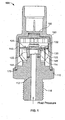
- Fig. 1 illustrates an example pressure measurement system 100.
- pressure measurement system 100 is a pressure sensor.
- Pressure measurement system 100 may measure the pressure of any appropriate fluid (e.g., liquid and/or gas).
- Pressure measurement system 100 includes a pressure inlet joint 110, a pressure detecting component 120, and a circuit board 130.
- Pressure inlet joint 110 which in certain implementations may be a socket, includes a passage 112 that ends in a chamber 114 formed by the pressure inlet joint and pressure detecting component 120.
- Pressure inlet joint also include threads 116 for securing system 100 to a process for which pressure is to be measured.
- pressure inlet joint 110 may be composed of stainless steel having high mechanical strength and corrosion-resistance.
- Pressure detecting component 120 includes a diaphragm 122, which may have a substantially cylindrical bottom. Diaphragm 122 may be metallic and has a strain gauge 124 formed on a surface opposite of the fluid-inlet side.
- strain gauges are provided at a number of locations (e.g., four) to form a bridge circuit and output an electric signal.
- Pressure detecting component 120 is coupled (e.g., fixed and sealed) to pressure inlet joint 110 (e.g., by welding).
- Circuit board 130 is electrically coupled to pressure detecting component 120 and conditions signals representative of pressure that the pressure detecting component generates.
- Circuit board 130 includes various electronic components 132 (e.g., filters, amplifiers, and processors) to condition the pressure-representative signals.
- Pressure measurement system 100 also includes a circuit board housing 140 (e.g., a shield case) that engages circuit board 130.
- circuit board housing 140 is substantially cylindrical and has a larger diameter section 142 and a smaller diameter section 144, the smaller diameter section being coupled to pressure inlet joint 110. Smaller diameter section 144 may be coupled (e.g., by resistance or laser welding) to pressure inlet joint 110 at multiple points. Larger diameter section 142 is adapted to couple to circuit board 130, which will be discussed in more detail below, although not all of the circuit board or its components need to be located in the larger diameter section.
- Circuit board housing 140 may or may not be vented to the atmosphere.
- circuit-board housing 140 may be electrically coupled to a ground line of circuit board 130 to provide increased noise resistance for the circuit board.
- Pressure measurement system 100 further includes an electrical connector 150, a system housing 160, and a gasket 170.
- Electrical connector 150 is coupled to system housing 160 and is electrically coupled to circuit board 130.
- electrical connector 150 and system housing 160 may be composed of an electrically insulating material.
- electrical connector 150 is integral with system housing 160.
- System housing 160 is also coupled to pressure inlet joint 110 (e.g., by caulking, crimping, or welding). System housing 160, in conjunction with pressure inlet joint 110, encloses circuit board housing 140.
- Gasket 170 interfaces with system housing 160 and pressure inlet joint 110 for preventing intrusion of moisture and dust from the outside.
- pressure inlet joint 110 is coupled (e.g., screwed and sealed) to a process for which a pressure is to be measured and allows pressure of a fluid to enter passage 112 and arrive at chamber 114.
- diaphragm 122 deforms, and strain gauge 124 senses the pressure as a strain and converts the pressure to an electrical signal, which is conveyed to circuit board 130.
- Circuit board 130 conditions (e.g., filters and amplifies) the electrical signal, which is then conveyed to electrical connector 150.
- Electrical connector 150 conveys the signal outside of system housing 160, so that the signal may be provided to a remote device.
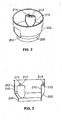
- FIGs. 2-3 illustrate an example of circuit board housing 140 - circuit board housing 200.
- Circuit board housing 200 includes a larger diameter section 202 and a smaller diameter section 204.
- Circuit board housing 200 may be composed of tin-plated soft steel, stainless steel, which may be matched to the pressure inlet joint, soft steel that may be readily formed, copper-based metal having good electrical characteristics, or any other appropriate material.
- Smaller diameter section 204 may engage a pressure inlet joint and be coupled thereto at a number of points (e.g., by spot welding).
- Circuit board housing 200 also includes three column sections 210.
- Column sections 210 have a substantially semi-circular cross section and extend from smaller diameter section 204 toward larger diameter section 202. The column sections are substantially parallel to the longitudinal axis of the circuit board housing. In other implementations, column sections 210 may have any other appropriate shapes and/or orientations.
- Each of column sections 210 includes a cover 212, which each includes a projection 214. Covers 212 can support a circuit board, and one or more of projections 214 may be coupled to the circuit board. Also, one or more of projections 214 may be electrically coupled to a ground line for the circuit board. The electrically-coupled projections may provide part of an electrical path from the circuit board to the pressure inlet joint.
- the circuit board housing may complete the path to the pressure inlet joint, and a ground line of the circuit board may be coupled to a projection via a capacitor and/or a varistor.
- the projections are arranged at unequal intervals around the housing.
- a circuit board is installed and supported on covers 212.
- the circuit board is then coupled to projections 214 (e.g., by engagement or soldering techniques). At least one of the couplings may allow a ground line of the circuit board to be electrically coupled to a projection.
- the projection may be pressed against a ground pad on the circuit board and bent thereon for engagement. In certain implementations, however, joint by soldering is preferable because of increased reliability.
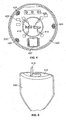
- FIG. 4 illustrates circuit board housing 200 engaged with a pressure detecting component 410 and a circuit board 420, which may be similar to pressure detecting component 120 and circuit board 130, respectively, of system 100.
- circuit board 420 is coupled to circuit board housing 200, and electrodes of a strain gauge arrangement 412 of pressure detecting component 410 are electrically coupled to electrodes of circuit board 420 by wire bonding 414.
- the pressure detecting component is directly connected to the circuit board by wire bonding in the illustrated implementation, a configuration may be employed in which the pressure detecting component is connected via a lead frame to the circuit board.
- Circuit board 420 also includes an amplifier 422, solder joints 424, a capacitor 426, and an input/output terminal 428.
- Amplifier 422 may, for example, be an integrated circuit.
- an electrical signal that is generated by pressure detecting component 410 and conditioned (e.g., amplified) by circuit board 420 is provided to input/output terminal 428, from which it may be sent via a relay board to an electrical connector for an external device.
- Input/output terminal 428 may serve as the basis of an amplified output (e.g., 0-5 Vdc ratiometric, 4-20 mA, and 0-10 Vdc).
- circuit board housing 140 has a variety of features. For example, when the circuit board is tightly coupled to the circuit board housing (e.g., by soldering), and the circuit board housing is tightly coupled to a pressure inlet joint with a pressure detecting component fixed thereon, a fixed portion of the circuit board is less susceptible to breaking. This allows a pressure measurement system with high reliability to be obtained. As another example, a ground terminal of the circuit board may be electrically coupled to a pressure inlet joint via the circuit board housing, which provides good grounding of the circuit board and an improvement in noise resistance. In particular implementations, an AC component superimposed on a DC power supply line can be released to the earth.
- this electrical coupling may be realized by soldering and welding, increasing the reliability of the coupling and reducing structural changes that may occur during the passage of time, which allows the noise resistance property to be maintained for a longer period of time.
- fixing the circuit board housing to a pressure inlet joint by spot welding an improvement in strength may be obtained.
- This increases reliability by providing a pressure measurement system capable of maintaining performance even in an environment in which vibration or impacts may occur.
- the area for mounting components on the rear surface of the circuit board is increased because the circuit board is coupled to the circuit board housing in the larger diameter section and the housing does not support the circuit board around its entire periphery.
- a diameter of the circuit board does not have to increase, and, as a result, the diameter of the pressure sensor does not have to increase. Further, by managing the height of covers 212, the height of the circuit board can readily be managed.
- column sections 210 are arranged in parallel to the longitudinal axis of the circuit board housing from the smaller diameter section to the larger diameter section, fabrication by press working can readily be performed. Namely, pressing work in the lateral direction in addition to processing in the vertical direction may be avoided. This may allow not only a less complicated structure of a die, but also easier die maintenance and increased press working speed, not to mention increased construction consistency.
- the pressing direction can be realized in the longitudinal direction also in the case of the projections, so that the pressure measurement system can be readily manufactured. Easing processing operations results in the circuit board housing being produced as a low cost member.
- the circuit board is coupled to the pressure inlet joint through a circuit board housing, which may be securely coupled to the pressure inlet joint. This may provide proper positioning of the circuit board, especially in the rotational direction, and a more lasting coupling, especially in high static or dynamic heat and/or load environments. If a circuit board loses its coupling to a pressure inlet port, disconnection of a wire electrically coupling the circuit board to a pressure detecting component may occur.
- the circuit board housing may be made of an electrically conductive material. This may improve the reliability of the circuit board housing and/or the interface between the circuit board housing and the pressure inlet joint by lessening the difference between thermal coefficients of expansion.
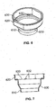
- FIG. 5 illustrates an example column section 500.
- Column section 500 is one example of column sections 210 for circuit board housing 200.
- column section 500 includes a cover 510 and a projection 512.
- Projection 512 is formed by cutting cover 510 and bending the cut portion.
- a projection may be formed by raising the cover with a form like a ball by a burring processing.
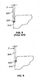
- Circuit board housing 600 includes a smaller diameter section 610 and a larger diameter section 620.
- a circuit board is held on a step 630 between the larger diameter section and the smaller diameter section.
- a projection 632 for coupling (e.g., by soldering) to a ground line of a circuit board may be provided according to the necessity.
- Smaller diameter section 610 may be engaged with a pressure inlet joint at multiple points and coupled thereto by spot welding (e.g., resistance welding or laser welding).
- Fig. 8 illustrates a conventional technique for coupling a circuit board housing 800 and a pressure inlet joint 810.
- Circuit board housing 800 and pressure inlet joint 810 may be similar to circuit board housing 140 and pressure inlet joint 110 of system 100.
- circuit board housing 800 and a pressure inlet joint 810 are coupled to each other by using seam welding, along a weld portion 830.
- a clearance is provided between circuit board housing 800 and pressure inlet joint 810.
- a force F in the lateral direction results in the stress being received by weld portion 830.
- a circuit board housing does not require high strength and, therefore, is commonly made with an iron plate with a thickness of approximately 0.5 mm or below by using press working techniques.
- the welded portion is integrated relatively weakly, and, as a result, the welded portion may easily break when a force F is loaded thereto.
- FIG. 9 illustrates another technique for coupling a circuit board housing 800 and a pressure inlet joint 810.
- circuit board housing 800 and pressure inlet joint 810 are coupled to each other by using spot welding, at a number of weld sections 840 (only one of which is shown).
- spot welding is performed at the welding sections 840
- circuit board housing 800 deforms slightly inward at the sections. Because of this feature, when a force F is applied to the circuit board housing, the section as a whole receives the force, so the stress is not concentrated at the welded section. This may result in the weld sections resisting breakage.
Landscapes
- Physics & Mathematics (AREA)
- General Physics & Mathematics (AREA)
- Measuring Fluid Pressure (AREA)
Applications Claiming Priority (2)
| Application Number | Priority Date | Filing Date | Title |
|---|---|---|---|
| US10/928,024 US7270010B2 (en) | 2004-08-27 | 2004-08-27 | System and method for pressure measurement |
| PCT/US2005/030297 WO2006026376A1 (en) | 2004-08-27 | 2005-08-25 | System and method for pressure measurement |
Publications (2)
| Publication Number | Publication Date |
|---|---|
| EP1800098A1 EP1800098A1 (en) | 2007-06-27 |
| EP1800098B1 true EP1800098B1 (en) | 2015-08-12 |
Family
ID=35427553
Family Applications (1)
| Application Number | Title | Priority Date | Filing Date |
|---|---|---|---|
| EP05791289.1A Expired - Lifetime EP1800098B1 (en) | 2004-08-27 | 2005-08-25 | System and method for pressure measurement |
Country Status (6)
| Country | Link |
|---|---|
| US (1) | US7270010B2 (enExample) |
| EP (1) | EP1800098B1 (enExample) |
| JP (1) | JP5091676B2 (enExample) |
| CN (1) | CN100552401C (enExample) |
| CA (1) | CA2576853C (enExample) |
| WO (1) | WO2006026376A1 (enExample) |
Families Citing this family (22)
| Publication number | Priority date | Publication date | Assignee | Title |
|---|---|---|---|---|
| JP4203678B2 (ja) * | 2006-12-07 | 2009-01-07 | Smc株式会社 | 圧力スイッチ |
| JP4403559B2 (ja) * | 2006-12-07 | 2010-01-27 | Smc株式会社 | 圧力スイッチ |
| US7779701B2 (en) * | 2008-06-02 | 2010-08-24 | Sensata Technologies, Inc. | Pressure sensor apparatus |
| JP5395412B2 (ja) * | 2008-11-25 | 2014-01-22 | パナソニック株式会社 | インタポーザ |
| US9354132B2 (en) * | 2009-02-12 | 2016-05-31 | Continental Automotive Systems, Inc. | Jointless pressure sensor port |
| US8156816B2 (en) * | 2010-05-27 | 2012-04-17 | Sensata Technologies, Inc. | Pressure sensor |
| CN102323836A (zh) * | 2011-05-10 | 2012-01-18 | 贵州航天电器股份有限公司 | 一种温度控制组件 |
| US8459125B2 (en) * | 2011-08-01 | 2013-06-11 | Honeywell International Inc. | Pressure sensor assembly |
| DE102012012527B4 (de) * | 2012-06-26 | 2015-05-21 | Krohne Analytics Gmbh | Messvorrichtung zum Bestimmen einer Prozessgröße |
| US9746390B2 (en) * | 2015-02-26 | 2017-08-29 | Sensata Technologies, Inc. | Microfused silicon strain gauge (MSG) pressure sensor package |
| CN107290099B (zh) | 2016-04-11 | 2021-06-08 | 森萨塔科技公司 | 压力传感器、用于压力传感器的插塞件和制造插塞件的方法 |
| EP3236226B1 (en) | 2016-04-20 | 2019-07-24 | Sensata Technologies, Inc. | Method of manufacturing a pressure sensor |
| US10545064B2 (en) | 2017-05-04 | 2020-01-28 | Sensata Technologies, Inc. | Integrated pressure and temperature sensor |
| US10323998B2 (en) * | 2017-06-30 | 2019-06-18 | Sensata Technologies, Inc. | Fluid pressure sensor |
| US10724907B2 (en) | 2017-07-12 | 2020-07-28 | Sensata Technologies, Inc. | Pressure sensor element with glass barrier material configured for increased capacitive response |
| US10557770B2 (en) | 2017-09-14 | 2020-02-11 | Sensata Technologies, Inc. | Pressure sensor with improved strain gauge |
| JP6793624B2 (ja) * | 2017-11-13 | 2020-12-02 | 株式会社鷺宮製作所 | 圧力センサ |
| CN108168766B (zh) * | 2018-01-09 | 2020-03-27 | 武汉飞恩微电子有限公司 | 一种重载压力传感器及其制造方法 |
| DE102019119426A1 (de) * | 2019-07-17 | 2021-01-21 | Endress+Hauser SE+Co. KG | Feldgerät der Automatisierungstechnik |
| CN112556919A (zh) * | 2020-12-10 | 2021-03-26 | 龙微科技无锡有限公司 | 一种新型耐腐蚀压力传感器模块 |
| DE102021122566A1 (de) * | 2021-08-31 | 2023-03-02 | Endress+Hauser SE+Co. KG | Feldgerät der Automatisierungstechnik |
| EP4469769A2 (en) * | 2022-03-17 | 2024-12-04 | Sensata Technologies, Inc. | Brake pedal with force sensor and membranes |
Family Cites Families (30)
| Publication number | Priority date | Publication date | Assignee | Title |
|---|---|---|---|---|
| JPH0650271B2 (ja) * | 1986-03-07 | 1994-06-29 | 太平洋工業株式会社 | 圧力検知装置 |
| US5174014A (en) * | 1990-07-27 | 1992-12-29 | Data Instruments, Inc. | Method of manufacturing pressure transducers |
| IT1257206B (it) | 1992-05-29 | 1996-01-10 | Fascia elastica di molleggio per sedili di autoveicoli. | |
| JPH0821775A (ja) * | 1994-07-08 | 1996-01-23 | Fuji Koki Seisakusho:Kk | 圧力センサ |
| JPH08105808A (ja) * | 1994-10-05 | 1996-04-23 | Mitsubishi Electric Corp | 圧力センサ |
| JP3440629B2 (ja) | 1995-04-25 | 2003-08-25 | 松下電工株式会社 | 圧力センサ |
| JPH10185735A (ja) * | 1996-12-27 | 1998-07-14 | Nagano Keiki Co Ltd | 圧力センサモジュール |
| US5880372A (en) * | 1997-01-10 | 1999-03-09 | Integrated Sensor Solutions | Media compatible pressure sensor device utilizing self-aligned components which fit together without the need for adhesives |
| US6089106A (en) * | 1998-09-04 | 2000-07-18 | Breed Automotive Technology, Inc. | Force sensor assembly |
| EP0995979B1 (de) | 1998-10-23 | 2003-07-23 | Endress + Hauser GmbH + Co. KG | Druckaufnehmer |
| JP2000155062A (ja) * | 1998-11-19 | 2000-06-06 | Nippon Seiki Co Ltd | 圧力検出器 |
| DE19916087A1 (de) * | 1999-04-09 | 2000-10-26 | Lucas Ind Plc | Anordnung zur Messung eines Fluiddrucks |
| CN2400795Y (zh) * | 1999-12-23 | 2000-10-11 | 王洪业 | 离子束溅射沉积薄膜压力传感器 |
| US6453747B1 (en) * | 2000-01-12 | 2002-09-24 | Peter A. Weise | Hermetic pressure transducer |
| JP2001208633A (ja) | 2000-01-27 | 2001-08-03 | Matsushita Electric Ind Co Ltd | 圧力センサ |
| DE10004408C1 (de) * | 2000-02-02 | 2001-06-21 | Paragon Sensors & Systems Ag | Mikrofonmodul |
| US6769308B1 (en) * | 2000-09-22 | 2004-08-03 | Delphi Technologies, Inc. | Low-cost stainless steel pressure sensor assembly for a pneumatic valve |
| US6584851B2 (en) * | 2000-11-30 | 2003-07-01 | Nagano Keiki Co., Ltd. | Fluid pressure sensor having a pressure port |
| JP3556165B2 (ja) * | 2000-11-30 | 2004-08-18 | 長野計器株式会社 | 圧力センサ |
| JP4356238B2 (ja) * | 2000-12-25 | 2009-11-04 | 株式会社デンソー | 圧力センサ |
| US6907789B2 (en) * | 2002-05-06 | 2005-06-21 | Honeywell International Inc. | Sensor package |
| US6722205B2 (en) * | 2002-06-24 | 2004-04-20 | Honeywell International, Inc. | Unitary pressure sensor housing and assembly |
| JP2004101515A (ja) | 2002-07-10 | 2004-04-02 | Texas Instruments Inc | 気密圧力変換器 |
| US6782758B2 (en) * | 2002-07-10 | 2004-08-31 | Texas Instruments Incorporated | Hermetic pressure transducer |
| US6823718B2 (en) * | 2002-10-28 | 2004-11-30 | Pti Technologies, Inc. | Single-body multiple sensing device |
| US6742395B1 (en) * | 2002-12-20 | 2004-06-01 | Texas Instruments Incorporated | Hermetic pressure transducer |
| US6866545B2 (en) * | 2003-03-10 | 2005-03-15 | Control Products, Inc., (Us) | Electrical cordset with integral signal conditioning circuitry |
| US6997059B2 (en) * | 2003-10-07 | 2006-02-14 | Cts Corporation | Pressure sensor |
| JP4301048B2 (ja) * | 2004-03-19 | 2009-07-22 | 株式会社デンソー | 圧力センサおよびその製造方法 |
| US7131334B2 (en) * | 2004-04-19 | 2006-11-07 | Celerity, Inc. | Pressure sensor device and method |
-
2004
- 2004-08-27 US US10/928,024 patent/US7270010B2/en not_active Expired - Fee Related
-
2005
- 2005-08-25 JP JP2007530136A patent/JP5091676B2/ja not_active Expired - Fee Related
- 2005-08-25 WO PCT/US2005/030297 patent/WO2006026376A1/en not_active Ceased
- 2005-08-25 CN CNB2005800286968A patent/CN100552401C/zh not_active Expired - Fee Related
- 2005-08-25 EP EP05791289.1A patent/EP1800098B1/en not_active Expired - Lifetime
- 2005-08-25 CA CA2576853A patent/CA2576853C/en not_active Expired - Fee Related
Also Published As
| Publication number | Publication date |
|---|---|
| WO2006026376A1 (en) | 2006-03-09 |
| CN100552401C (zh) | 2009-10-21 |
| JP5091676B2 (ja) | 2012-12-05 |
| CN101040176A (zh) | 2007-09-19 |
| CA2576853A1 (en) | 2006-03-09 |
| US20060042393A1 (en) | 2006-03-02 |
| CA2576853C (en) | 2014-05-06 |
| JP2008511833A (ja) | 2008-04-17 |
| US7270010B2 (en) | 2007-09-18 |
| EP1800098A1 (en) | 2007-06-27 |
Similar Documents
| Publication | Publication Date | Title |
|---|---|---|
| EP1800098B1 (en) | System and method for pressure measurement | |
| US7152483B2 (en) | High pressure sensor comprising silicon membrane and solder layer | |
| KR100590275B1 (ko) | 압력 센서 | |
| US6584851B2 (en) | Fluid pressure sensor having a pressure port | |
| JP3987386B2 (ja) | 圧力センサ | |
| JP4075776B2 (ja) | 物理量センサおよび圧力センサ | |
| US6474170B1 (en) | Pressure sensor | |
| US6745633B2 (en) | Pressure sensor with electrically conductive spring bodies for connecting and fixing connector case and pads | |
| US6619132B2 (en) | Sensor including a circuit lead frame and a terminal lead frame formed by a metal plate | |
| EP1584911B1 (en) | Housing for a pressure sensor and method for manufacturing the same | |
| JP4863571B2 (ja) | 圧力センサ | |
| JP2008185349A (ja) | 圧力センサ | |
| CN221803214U (zh) | 一种微熔硅应变计压力传感器封装结构 | |
| JP4223273B2 (ja) | 圧力センサ | |
| JP2005249471A (ja) | 圧力センサおよびその製造方法 | |
| JP3722191B2 (ja) | 半導体圧力センサ | |
| JP3751528B2 (ja) | センサ及び圧力センサ | |
| JPH1194665A (ja) | 圧力センサ | |
| JP2000249615A (ja) | 半導体圧力センサ | |
| JP2017032389A (ja) | 圧力センサ | |
| JP3182753B2 (ja) | 圧力検出器 | |
| JP2000105162A (ja) | 圧力センサ | |
| JPH06288850A (ja) | 圧力センサ | |
| JP2006184075A (ja) | 圧力センサ | |
| JP2005249513A (ja) | 圧力検出装置 |
Legal Events
| Date | Code | Title | Description |
|---|---|---|---|
| PUAI | Public reference made under article 153(3) epc to a published international application that has entered the european phase |
Free format text: ORIGINAL CODE: 0009012 |
|
| 17P | Request for examination filed |
Effective date: 20070215 |
|
| AK | Designated contracting states |
Kind code of ref document: A1 Designated state(s): AT BE BG CH CY CZ DE DK EE ES FI FR GB GR HU IE IS IT LI LT LU LV MC NL PL PT RO SE SI SK TR |
|
| DAX | Request for extension of the european patent (deleted) | ||
| 17Q | First examination report despatched |
Effective date: 20110905 |
|
| GRAP | Despatch of communication of intention to grant a patent |
Free format text: ORIGINAL CODE: EPIDOSNIGR1 |
|
| INTG | Intention to grant announced |
Effective date: 20150302 |
|
| GRAS | Grant fee paid |
Free format text: ORIGINAL CODE: EPIDOSNIGR3 |
|
| GRAA | (expected) grant |
Free format text: ORIGINAL CODE: 0009210 |
|
| AK | Designated contracting states |
Kind code of ref document: B1 Designated state(s): AT BE BG CH CY CZ DE DK EE ES FI FR GB GR HU IE IS IT LI LT LU LV MC NL PL PT RO SE SI SK TR |
|
| REG | Reference to a national code |
Ref country code: GB Ref legal event code: FG4D |
|
| REG | Reference to a national code |
Ref country code: CH Ref legal event code: EP |
|
| REG | Reference to a national code |
Ref country code: AT Ref legal event code: REF Ref document number: 742588 Country of ref document: AT Kind code of ref document: T Effective date: 20150815 |
|
| REG | Reference to a national code |
Ref country code: IE Ref legal event code: FG4D |
|
| REG | Reference to a national code |
Ref country code: DE Ref legal event code: R096 Ref document number: 602005047243 Country of ref document: DE |
|
| REG | Reference to a national code |
Ref country code: LT Ref legal event code: MG4D |
|
| REG | Reference to a national code |
Ref country code: AT Ref legal event code: MK05 Ref document number: 742588 Country of ref document: AT Kind code of ref document: T Effective date: 20150812 |
|
| REG | Reference to a national code |
Ref country code: NL Ref legal event code: MP Effective date: 20150812 |
|
| PG25 | Lapsed in a contracting state [announced via postgrant information from national office to epo] |
Ref country code: FI Free format text: LAPSE BECAUSE OF FAILURE TO SUBMIT A TRANSLATION OF THE DESCRIPTION OR TO PAY THE FEE WITHIN THE PRESCRIBED TIME-LIMIT Effective date: 20150812 Ref country code: GR Free format text: LAPSE BECAUSE OF FAILURE TO SUBMIT A TRANSLATION OF THE DESCRIPTION OR TO PAY THE FEE WITHIN THE PRESCRIBED TIME-LIMIT Effective date: 20151113 Ref country code: LT Free format text: LAPSE BECAUSE OF FAILURE TO SUBMIT A TRANSLATION OF THE DESCRIPTION OR TO PAY THE FEE WITHIN THE PRESCRIBED TIME-LIMIT Effective date: 20150812 Ref country code: LV Free format text: LAPSE BECAUSE OF FAILURE TO SUBMIT A TRANSLATION OF THE DESCRIPTION OR TO PAY THE FEE WITHIN THE PRESCRIBED TIME-LIMIT Effective date: 20150812 |
|
| PG25 | Lapsed in a contracting state [announced via postgrant information from national office to epo] |
Ref country code: PL Free format text: LAPSE BECAUSE OF FAILURE TO SUBMIT A TRANSLATION OF THE DESCRIPTION OR TO PAY THE FEE WITHIN THE PRESCRIBED TIME-LIMIT Effective date: 20150812 Ref country code: IS Free format text: LAPSE BECAUSE OF FAILURE TO SUBMIT A TRANSLATION OF THE DESCRIPTION OR TO PAY THE FEE WITHIN THE PRESCRIBED TIME-LIMIT Effective date: 20151212 Ref country code: SE Free format text: LAPSE BECAUSE OF FAILURE TO SUBMIT A TRANSLATION OF THE DESCRIPTION OR TO PAY THE FEE WITHIN THE PRESCRIBED TIME-LIMIT Effective date: 20150812 Ref country code: AT Free format text: LAPSE BECAUSE OF FAILURE TO SUBMIT A TRANSLATION OF THE DESCRIPTION OR TO PAY THE FEE WITHIN THE PRESCRIBED TIME-LIMIT Effective date: 20150812 Ref country code: PT Free format text: LAPSE BECAUSE OF FAILURE TO SUBMIT A TRANSLATION OF THE DESCRIPTION OR TO PAY THE FEE WITHIN THE PRESCRIBED TIME-LIMIT Effective date: 20151214 Ref country code: ES Free format text: LAPSE BECAUSE OF FAILURE TO SUBMIT A TRANSLATION OF THE DESCRIPTION OR TO PAY THE FEE WITHIN THE PRESCRIBED TIME-LIMIT Effective date: 20150812 |
|
| PG25 | Lapsed in a contracting state [announced via postgrant information from national office to epo] |
Ref country code: NL Free format text: LAPSE BECAUSE OF FAILURE TO SUBMIT A TRANSLATION OF THE DESCRIPTION OR TO PAY THE FEE WITHIN THE PRESCRIBED TIME-LIMIT Effective date: 20150812 |
|
| REG | Reference to a national code |
Ref country code: CH Ref legal event code: PL |
|
| PG25 | Lapsed in a contracting state [announced via postgrant information from national office to epo] |
Ref country code: DK Free format text: LAPSE BECAUSE OF FAILURE TO SUBMIT A TRANSLATION OF THE DESCRIPTION OR TO PAY THE FEE WITHIN THE PRESCRIBED TIME-LIMIT Effective date: 20150812 Ref country code: CZ Free format text: LAPSE BECAUSE OF FAILURE TO SUBMIT A TRANSLATION OF THE DESCRIPTION OR TO PAY THE FEE WITHIN THE PRESCRIBED TIME-LIMIT Effective date: 20150812 Ref country code: EE Free format text: LAPSE BECAUSE OF FAILURE TO SUBMIT A TRANSLATION OF THE DESCRIPTION OR TO PAY THE FEE WITHIN THE PRESCRIBED TIME-LIMIT Effective date: 20150812 Ref country code: CH Free format text: LAPSE BECAUSE OF NON-PAYMENT OF DUE FEES Effective date: 20150831 Ref country code: SK Free format text: LAPSE BECAUSE OF FAILURE TO SUBMIT A TRANSLATION OF THE DESCRIPTION OR TO PAY THE FEE WITHIN THE PRESCRIBED TIME-LIMIT Effective date: 20150812 Ref country code: IT Free format text: LAPSE BECAUSE OF FAILURE TO SUBMIT A TRANSLATION OF THE DESCRIPTION OR TO PAY THE FEE WITHIN THE PRESCRIBED TIME-LIMIT Effective date: 20150812 Ref country code: LI Free format text: LAPSE BECAUSE OF NON-PAYMENT OF DUE FEES Effective date: 20150831 |
|
| REG | Reference to a national code |
Ref country code: DE Ref legal event code: R097 Ref document number: 602005047243 Country of ref document: DE |
|
| PG25 | Lapsed in a contracting state [announced via postgrant information from national office to epo] |
Ref country code: MC Free format text: LAPSE BECAUSE OF FAILURE TO SUBMIT A TRANSLATION OF THE DESCRIPTION OR TO PAY THE FEE WITHIN THE PRESCRIBED TIME-LIMIT Effective date: 20150812 Ref country code: RO Free format text: LAPSE BECAUSE OF FAILURE TO SUBMIT A TRANSLATION OF THE DESCRIPTION OR TO PAY THE FEE WITHIN THE PRESCRIBED TIME-LIMIT Effective date: 20150812 |
|
| REG | Reference to a national code |
Ref country code: IE Ref legal event code: MM4A |
|
| PLBE | No opposition filed within time limit |
Free format text: ORIGINAL CODE: 0009261 |
|
| STAA | Information on the status of an ep patent application or granted ep patent |
Free format text: STATUS: NO OPPOSITION FILED WITHIN TIME LIMIT |
|
| 26N | No opposition filed |
Effective date: 20160513 |
|
| PG25 | Lapsed in a contracting state [announced via postgrant information from national office to epo] |
Ref country code: IE Free format text: LAPSE BECAUSE OF NON-PAYMENT OF DUE FEES Effective date: 20150825 |
|
| REG | Reference to a national code |
Ref country code: FR Ref legal event code: PLFP Year of fee payment: 12 |
|
| PG25 | Lapsed in a contracting state [announced via postgrant information from national office to epo] |
Ref country code: SI Free format text: LAPSE BECAUSE OF FAILURE TO SUBMIT A TRANSLATION OF THE DESCRIPTION OR TO PAY THE FEE WITHIN THE PRESCRIBED TIME-LIMIT Effective date: 20150812 |
|
| PG25 | Lapsed in a contracting state [announced via postgrant information from national office to epo] |
Ref country code: BG Free format text: LAPSE BECAUSE OF FAILURE TO SUBMIT A TRANSLATION OF THE DESCRIPTION OR TO PAY THE FEE WITHIN THE PRESCRIBED TIME-LIMIT Effective date: 20150812 Ref country code: HU Free format text: LAPSE BECAUSE OF FAILURE TO SUBMIT A TRANSLATION OF THE DESCRIPTION OR TO PAY THE FEE WITHIN THE PRESCRIBED TIME-LIMIT; INVALID AB INITIO Effective date: 20050825 |
|
| PG25 | Lapsed in a contracting state [announced via postgrant information from national office to epo] |
Ref country code: CY Free format text: LAPSE BECAUSE OF FAILURE TO SUBMIT A TRANSLATION OF THE DESCRIPTION OR TO PAY THE FEE WITHIN THE PRESCRIBED TIME-LIMIT Effective date: 20150812 |
|
| PG25 | Lapsed in a contracting state [announced via postgrant information from national office to epo] |
Ref country code: BE Free format text: LAPSE BECAUSE OF NON-PAYMENT OF DUE FEES Effective date: 20150831 |
|
| REG | Reference to a national code |
Ref country code: FR Ref legal event code: PLFP Year of fee payment: 13 |
|
| PG25 | Lapsed in a contracting state [announced via postgrant information from national office to epo] |
Ref country code: TR Free format text: LAPSE BECAUSE OF FAILURE TO SUBMIT A TRANSLATION OF THE DESCRIPTION OR TO PAY THE FEE WITHIN THE PRESCRIBED TIME-LIMIT Effective date: 20150812 |
|
| PGFP | Annual fee paid to national office [announced via postgrant information from national office to epo] |
Ref country code: MC Payment date: 20170428 Year of fee payment: 12 |
|
| PG25 | Lapsed in a contracting state [announced via postgrant information from national office to epo] |
Ref country code: LU Free format text: LAPSE BECAUSE OF NON-PAYMENT OF DUE FEES Effective date: 20150825 |
|
| PG25 | Lapsed in a contracting state [announced via postgrant information from national office to epo] |
Ref country code: FR Free format text: LAPSE BECAUSE OF NON-PAYMENT OF DUE FEES Effective date: 20180831 |
|
| PGFP | Annual fee paid to national office [announced via postgrant information from national office to epo] |
Ref country code: DE Payment date: 20191029 Year of fee payment: 15 |
|
| PGFP | Annual fee paid to national office [announced via postgrant information from national office to epo] |
Ref country code: GB Payment date: 20191028 Year of fee payment: 15 |
|
| REG | Reference to a national code |
Ref country code: DE Ref legal event code: R119 Ref document number: 602005047243 Country of ref document: DE |
|
| GBPC | Gb: european patent ceased through non-payment of renewal fee |
Effective date: 20200825 |
|
| PG25 | Lapsed in a contracting state [announced via postgrant information from national office to epo] |
Ref country code: DE Free format text: LAPSE BECAUSE OF NON-PAYMENT OF DUE FEES Effective date: 20210302 |
|
| PG25 | Lapsed in a contracting state [announced via postgrant information from national office to epo] |
Ref country code: GB Free format text: LAPSE BECAUSE OF NON-PAYMENT OF DUE FEES Effective date: 20200825 |