EP1792684A1 - Elektrodenspritznachbearbeitung. - Google Patents
Elektrodenspritznachbearbeitung. Download PDFInfo
- Publication number
- EP1792684A1 EP1792684A1 EP06110302A EP06110302A EP1792684A1 EP 1792684 A1 EP1792684 A1 EP 1792684A1 EP 06110302 A EP06110302 A EP 06110302A EP 06110302 A EP06110302 A EP 06110302A EP 1792684 A1 EP1792684 A1 EP 1792684A1
- Authority
- EP
- European Patent Office
- Prior art keywords
- electrode
- tip
- electrode tips
- dressing
- electrode tip
- Prior art date
- Legal status (The legal status is an assumption and is not a legal conclusion. Google has not performed a legal analysis and makes no representation as to the accuracy of the status listed.)
- Withdrawn
Links
- 230000002093 peripheral effect Effects 0.000 claims abstract description 44
- 238000003466 welding Methods 0.000 claims abstract description 40
- 238000000034 method Methods 0.000 claims description 24
- 230000008569 process Effects 0.000 claims description 23
- 238000005520 cutting process Methods 0.000 claims description 22
- 230000000452 restraining effect Effects 0.000 claims description 16
- 230000015572 biosynthetic process Effects 0.000 description 8
- 239000000463 material Substances 0.000 description 8
- 238000009434 installation Methods 0.000 description 6
- 230000008901 benefit Effects 0.000 description 4
- 230000006835 compression Effects 0.000 description 4
- 238000007906 compression Methods 0.000 description 4
- 238000012986 modification Methods 0.000 description 2
- 230000004048 modification Effects 0.000 description 2
- 230000004044 response Effects 0.000 description 2
- 229910001315 Tool steel Inorganic materials 0.000 description 1
- ZTXONRUJVYXVTJ-UHFFFAOYSA-N chromium copper Chemical compound [Cr][Cu][Cr] ZTXONRUJVYXVTJ-UHFFFAOYSA-N 0.000 description 1
- 239000000470 constituent Substances 0.000 description 1
- 230000008602 contraction Effects 0.000 description 1
- 230000000694 effects Effects 0.000 description 1
- 238000005498 polishing Methods 0.000 description 1
- 230000002035 prolonged effect Effects 0.000 description 1
Images




Classifications
-
- B—PERFORMING OPERATIONS; TRANSPORTING
- B23—MACHINE TOOLS; METAL-WORKING NOT OTHERWISE PROVIDED FOR
- B23K—SOLDERING OR UNSOLDERING; WELDING; CLADDING OR PLATING BY SOLDERING OR WELDING; CUTTING BY APPLYING HEAT LOCALLY, e.g. FLAME CUTTING; WORKING BY LASER BEAM
- B23K11/00—Resistance welding; Severing by resistance heating
- B23K11/30—Features relating to electrodes
- B23K11/3063—Electrode maintenance, e.g. cleaning, grinding
-
- B—PERFORMING OPERATIONS; TRANSPORTING
- B23—MACHINE TOOLS; METAL-WORKING NOT OTHERWISE PROVIDED FOR
- B23K—SOLDERING OR UNSOLDERING; WELDING; CLADDING OR PLATING BY SOLDERING OR WELDING; CUTTING BY APPLYING HEAT LOCALLY, e.g. FLAME CUTTING; WORKING BY LASER BEAM
- B23K11/00—Resistance welding; Severing by resistance heating
- B23K11/10—Spot welding; Stitch welding
- B23K11/11—Spot welding
- B23K11/115—Spot welding by means of two electrodes placed opposite one another on both sides of the welded parts
-
- B—PERFORMING OPERATIONS; TRANSPORTING
- B23—MACHINE TOOLS; METAL-WORKING NOT OTHERWISE PROVIDED FOR
- B23K—SOLDERING OR UNSOLDERING; WELDING; CLADDING OR PLATING BY SOLDERING OR WELDING; CUTTING BY APPLYING HEAT LOCALLY, e.g. FLAME CUTTING; WORKING BY LASER BEAM
- B23K11/00—Resistance welding; Severing by resistance heating
- B23K11/36—Auxiliary equipment
-
- B—PERFORMING OPERATIONS; TRANSPORTING
- B24—GRINDING; POLISHING
- B24B—MACHINES, DEVICES, OR PROCESSES FOR GRINDING OR POLISHING; DRESSING OR CONDITIONING OF ABRADING SURFACES; FEEDING OF GRINDING, POLISHING, OR LAPPING AGENTS
- B24B19/00—Single-purpose machines or devices for particular grinding operations not covered by any other main group
- B24B19/16—Single-purpose machines or devices for particular grinding operations not covered by any other main group for grinding sharp-pointed workpieces, e.g. needles, pens, fish hooks, tweezers or record player styli
-
- B—PERFORMING OPERATIONS; TRANSPORTING
- B24—GRINDING; POLISHING
- B24B—MACHINES, DEVICES, OR PROCESSES FOR GRINDING OR POLISHING; DRESSING OR CONDITIONING OF ABRADING SURFACES; FEEDING OF GRINDING, POLISHING, OR LAPPING AGENTS
- B24B53/00—Devices or means for dressing or conditioning abrasive surfaces
- B24B53/04—Devices or means for dressing or conditioning abrasive surfaces of cylindrical or conical surfaces on abrasive tools or wheels
-
- B—PERFORMING OPERATIONS; TRANSPORTING
- B24—GRINDING; POLISHING
- B24B—MACHINES, DEVICES, OR PROCESSES FOR GRINDING OR POLISHING; DRESSING OR CONDITIONING OF ABRADING SURFACES; FEEDING OF GRINDING, POLISHING, OR LAPPING AGENTS
- B24B9/00—Machines or devices designed for grinding edges or bevels on work or for removing burrs; Accessories therefor
- B24B9/02—Machines or devices designed for grinding edges or bevels on work or for removing burrs; Accessories therefor characterised by a special design with respect to properties of materials specific to articles to be ground
- B24B9/04—Machines or devices designed for grinding edges or bevels on work or for removing burrs; Accessories therefor characterised by a special design with respect to properties of materials specific to articles to be ground of metal, e.g. skate blades
-
- Y—GENERAL TAGGING OF NEW TECHNOLOGICAL DEVELOPMENTS; GENERAL TAGGING OF CROSS-SECTIONAL TECHNOLOGIES SPANNING OVER SEVERAL SECTIONS OF THE IPC; TECHNICAL SUBJECTS COVERED BY FORMER USPC CROSS-REFERENCE ART COLLECTIONS [XRACs] AND DIGESTS
- Y10—TECHNICAL SUBJECTS COVERED BY FORMER USPC
- Y10T—TECHNICAL SUBJECTS COVERED BY FORMER US CLASSIFICATION
- Y10T29/00—Metal working
- Y10T29/51—Plural diverse manufacturing apparatus including means for metal shaping or assembling
- Y10T29/5191—Assembly
-
- Y—GENERAL TAGGING OF NEW TECHNOLOGICAL DEVELOPMENTS; GENERAL TAGGING OF CROSS-SECTIONAL TECHNOLOGIES SPANNING OVER SEVERAL SECTIONS OF THE IPC; TECHNICAL SUBJECTS COVERED BY FORMER USPC CROSS-REFERENCE ART COLLECTIONS [XRACs] AND DIGESTS
- Y10—TECHNICAL SUBJECTS COVERED BY FORMER USPC
- Y10T—TECHNICAL SUBJECTS COVERED BY FORMER US CLASSIFICATION
- Y10T409/00—Gear cutting, milling, or planing
- Y10T409/30—Milling
- Y10T409/3042—Means to remove scale or raised surface imperfection
- Y10T409/304256—Means to remove flash or burr
Definitions
- the present invention relates to an electrode tip dresser which dresses a pair of electrode tips held in a welding gun for spot welding while minimizing a grinding task inevitably involving formation of swarf.
- an electrode tip dresser When an electrode tip is dressed using such an electrode tip dresser, it is possible to reduce the loss of the material of the electrode tip, as compared to traditional methods in which the electrode tip is dressed using a polishing or grinding process. For this reason, such an electrode tip dresser has been advantageously used for an electrode tip, which is used in a spot welding task, in that it is possible to reduce the loss of the material of the electrode tip, and thus, to use the electrode tip for a prolonged period of time.
- the electrode tip which is used in a spot welding task, has a tip section, and a cylindrical shank section.
- the tip section of the electrode tip has a circular tip surface that contacts a work piece to be welded, and an enlarged diameter portion having a diameter increasing as it extends from the peripheral edge of the tip surface to the shank section.
- the electrode tip which has been deformed after being used in a certain number of welding processes, is pressed on a die at a high pressure in the above-mentioned conventional electrode tip dresser, to plastically deform the tip portion of the electrode tip, and thus, to dress (regenerate) the electrode tip.
- the present invention is directed to an electrode tip dresser that substantially obviates one or more problems due to limitations and disadvantages of the related art.
- An object of the present invention is to provide an electrode tip dresser which can dress a pair of electrode tips to a usable state while achieving a desired accuracy of a tip surface of each electrode tip including an angular portion at a peripheral edge of the tip surface, without separating each electrode tip from a welding gun.
- the electrode tips held by the welding gun are moved toward each other and into the holder such that the electrode tips are pressed against the dressing rollers, respectively.
- the dressing rollers then rotate in a circumferential direction about the common axis of the electrode tips, together with the holder, while rotating about respective support shafts.
- the dressing rollers dress the electrode tips such that the electrode tips have a shape conforming to that of the grooves of the dressing rollers.
- each of the dressing rollers is divided into two divided roller bodies arranged at opposite sides of the dividing plane positioned at the center of the tip surface of the associated electrode tip in a direction orthogonal to the axis of the electrode tip, the divided roller bodies of the dressing roller dress the tip surface and enlarged diameter portion of the electrode tip while rotating in opposite directions, respectively, during the rotation of the holder. Since the divided roller bodies can continuously dress an integrated portion of the associated electrode tip extending from the tip surface to the enlarged diameter portion via the angular portion formed at the peripheral edge of the tip surface, it is possible to accurately dress the tip-section-side portions of each electrode tip, namely, the tip surface and the angular portion arranged at the peripheral edge of the tip surface, to desired shapes, respectively.
- the contact between the dressing rollers and the associated electrode tips is approximately linear contact in an axial direction of the outer peripheral surfaces of the dressing rollers. Accordingly, it is possible to plastically deform the electrode tips at a low speed, even using a small pressure applied to the electrode tips by the welding gun such that the electrode tips are moved toward each other, and thus, to dress the electrode tips to a desired shape.
- the electrode tip dresser can rapidly dress (regenerate) the electrode tips to a usable state because it is possible to secure a desired accuracy of the tip surface of each electrode tip including the angular portion at the peripheral edge of the tip surface without separating the electrode tips and without resulting in formation of swarf.
- the support shafts may extend orthogonally to each other.
- Each dressing roller has an approximately hourglass-shaped structure such that the dressing roller has the groove which has a cross-section conforming to the outline of the tip section of the associated electrode tip when the cross-section is taken in a direction orthogonal to the associated support shaft, and enlarged diameter portions which are arranged at opposite axial ends of the dressing roller. Accordingly, when the dressing rollers are arranged such that the support shafts thereof are orthogonal to each other, it is possible to closely arrange the support shafts without causing the enlarged diameter portions of the dressing rollers to interfere with each other. Therefore, it is possible to reduce the installation space of the dressing rollers, as compared to the case in which the dressing rollers are arranged such that the support shafts are parallel to each other. Thus, it is possible to reduce the volume, in particular, thickness, of the holder. By virtue of this fact, it is possible to install the electrode tip dresser within a reduced space in a place where a welding task is carried out.
- Guide members may be arranged in the vicinity of the holder.
- the guide members may be provided with guide holes to guide the electrode tips when the electrode tips are pressed against the dressing rollers, respectively, such that the shank sections of the electrode tips are prevented from being joggled in a direction orthogonal to the common axis of the electrode tips during a dressing process.
- the dressing rollers have a small outer diameter
- This possibility can be prevented by restraining the outer peripheral surface of the shank sections of each electrode tip by the inner peripheral surface of the guide hole of the associated guide member. That is, it is possible to smoothly dress the electrode tips even when the dressing rollers are configured to have a small outer diameter in order to reduce the installation space of the electrode tip dresser.
- the electrode tips are moved toward each other and into the holder such that the electrode tips are pressed against the dressing rollers, respectively.
- the dressing rollers then rotate in a circumferential direction about the common axis of the electrode tips, together with the holder.
- the divided roller bodies of each dressing roller are rotated about the associated support shaft, thereby dressing the enlarged diameter portion of the associated electrode tip such that the enlarged diameter portion has a shape conforming to that of the grooves of the divided roller bodies.
- the cutter cuts the tip surface of the associated electrode tip using the cutting blade, to dress the tip surface.
- each divided roller body includes the main portion which has a cross-section conforming to the outline of the enlarged diameter portion of the associated electrode tip, and the extension portion which is connected to the main portion, is arranged at the side of the cutter, and extends from the main portion toward the associated support shaft, when the cross-section is taken in a direction orthogonal to the axis of the support shaft, and the outline is taken after the dressing of the electrode tip. Accordingly, when the divided roller bodies of each dressing roller dress the enlarged diameter portion of the associated electrode tip by plastically deforming the enlarged diameter portion, a surplus portion of the tip material of the electrode tip is extruded from the main portion of the groove along the extension portion. The extruded surplus portion of the tip material is cut by the cutting blade of the cutter. Thus, it is possible to dress the tip section of each electrode tip, namely, the tip surface and the angular portion formed at the peripheral edge of the tip surface, to a desired shape with a high accuracy.
- each electrode tip Since the enlarged diameter portion of each electrode tip is not cut during the dressing process, even though the tip surface of each electrode tip is cut, it is possible to suppress formation of swarf as much as possible. That is, it is possible to dress the electrode tips while suppressing the consumption of the tip material.
- the electrode tip dresser can rapidly dress the electrode tips to a usable state because it is possible to secure a desired accuracy of the tip surface of each electrode tip including the angular portion at the peripheral edge of the tip surface without separating the electrode tips and while suppressing formation of swarf as much as possible.
- the cutter may include restraining surfaces which are arranged at opposite sides of the cutting blade in the direction orthogonal to the axis of the associated support shaft, respectively, to restrain the enlarged diameter portion of the associated electrode tip, and thus, to prevent the associated electrode tip from joggling in the direction orthogonal to the axis of the electrode tip during a dressing process. Accordingly, even in the case in which the dressing rollers have a small outer diameter, it is possible to prevent the electrode tips from escaping from the outer peripheral surfaces of the dressing rollers when the electrode tips are pressed against the dressing rollers, respectively. This is because the electrode tips are restrained by the restraining surfaces of the cutters. Accordingly, it is possible to smoothly dress the electrode tips even when the dressing rollers are configured to have a small outer diameter in order to reduce the installation space of the electrode tip dresser.
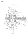
- FIG. 1 is a side view illustrating a part of an electrode tip dresser according to a first embodiment of the present invention
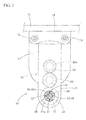
- FIG. 2 is a schematic plan view illustrating the electrode tip dresser according to the first embodiment of the present invention
- FIG. 3 is a longitudinal sectional view illustrating a main part of the electrode tip dresser according to the first embodiment of the present invention
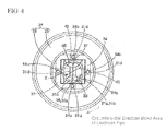
- FIG. 4 is a schematic plan view illustrating a dresser body of the electrode tip dresser according to the first embodiment of the present invention
- FIG. 5 is an exploded perspective view illustrating dressing rollers, support shafts, and a holder which are included in the electrode tip dresser according to the first embodiment of the present invention
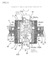
- FIG. 6 is a sectional view illustrating a part of the electrode tip dresser according to the first embodiment of the present invention during a dressing process
- FIG. 7 is a sectional view illustrating dressing rollers according to a modified example of the first embodiment of the present invention.
- FIG. 8 is an exploded perspective view illustrating dressing rollers, support shafts, and a holder which are included in an electrode tip dresser according to a second embodiment of the present invention
- FIG. 9 is a front view illustrating a cutter included in the electrode tip dresser according to the second embodiment of the present invention.
- FIG. 10 is a cross-sectional view taken along the line X - X in FIG. 9, illustrating the cutter included in the electrode tip dresser according to the second embodiment of the present invention
- FIG. 11 is a cross-sectional view taken along the line XI - XI in FIG. 9, illustrating a part of the cutter included in the electrode tip dresser according to the second embodiment of the present invention
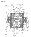
- FIG. 12 is a sectional view illustrating a part of the electrode tip dresser according to the second embodiment of the present invention during a dressing process
- FIG. 13 is a cross-sectional view taken along the line XIII - XIII in FIG. 12, illustrating a part of the electrode tip dresser according to the second embodiment of the present invention during a dressing process;
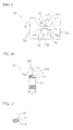
- FIG. 14 is a schematic view explaining the rotation trace of grooves formed at a pair of divided roller bodies with respect to a cutting blade of the cutter in the electrode tip dresser according to the second embodiment of the present invention during rotation of the holder.
- an electrode tip dresser Ml according to a first embodiment of the present invention is illustrated.
- the electrode tip dresser Ml according to the first embodiment of the present invention is adapted to dress a pair of electrode tips 6, namely, electrode tips 6A and 6B, respectively fitted in shanks 3 and 4 of a welding gun 1.
- the welding gun 1 is a servo gun which is mounted to a front end of an arm of a multi-joint welding robot not shown.
- the welding gun or servo gun 1 has a well-known structure having functions for holding the electrode tips 6A and 6B and moving the electrode tips 6A and 6B in accordance with operation of a servo motor 2 equipped with a built-in encoder, and a position control function for controlling relative movements of the electrode tips 6A and 6B with respect to each other.
- the servo gun 1 also has an operating function to control the RPM and torque of the servo motor 2, and to control the positions and pressure of the electrode tips 6A and 6B.
- Each of the electrode tips 6A and 6B includes a tip section which contacts a work piece during a welding process, and a cylindrical shank section 6d.
- the tip section has a circular tip surface 6a, and an enlarged diameter portion 6c having a diameter increasing as the enlarged diameter portion 6c extends from a peripheral edge (angular portion) 6b of the tip surface 6a to the cylindrical shank section 6d.
- the enlarged diameter portion 6c has an approximately hemispherical shape.
- the tip surface 6a has a diameter d of 6 mm
- the shank section 6d has a diameter D of 16 mm. The diameters d and D are indicated in FIG. 3.
- the electrode tip dresser Ml is arranged within a movement range of the servo gun 1 moved by operation of the welding robot. As shown in FIGs. 1 to 3, the electrode tip dresser Ml includes a support frame 10, a guide block 14, a gear case 16, a drive motor 222, and a dresser body 26.
- Upper and lower brackets 11 and 12 are fixed to the support frame 10 arranged within the movement range of the servo gun 1.
- a pair of guide rods 13 extend vertically between the upper and lower brackets 11 and 13 at opposite sides of each bracket. Opposite ends of each guide rod 13 are mounted to the upper and lower brackets 11 and 13, respectively.
- the guide rods 13 extend vertically through the guide block 14 which is arranged at an approximately intermediate position between the upper and lower brackets 11 and 13. Accordingly, the guide block 14 is supported by the guide rods 13 such that the guide block 14 is slidable in an axial direction of the guide rods 13, namely, a vertical direction.
- a pair of compression coil springs 15 are fitted around each guide rod 13 at upper and lower sides of the guide block 14, respectively.
- each guide rod 13 is arranged between the upper bracket 11 and the upper surface of the guide block 14, whereas the other compression coil spring 15 fitted around each guide rod 13 is arranged between the lower surface of the guide block 14 and the lower bracket 12.
- the guide block 14 is supported by the support frame 10 such that the guide block 14 is vertically movable in accordance with extension and contraction of the compression coil springs 15 caused by axial movements of the electrode tips 6A and 6B.
- the gear case 16 is mounted on a front portion of the guide block 14.
- the gear case 16 includes an upper plate 18, and a lower plate 19 vertically spaced apart from the upper plate 18.
- a rotating barrel 27 is fitted in an opening formed through the front portion of the guide block 14, and is rotatably supported by bearings 20 arranged around the opening between the upper plate 18 and the lower plate 18.
- a cover 17 is mounted on the upper plate 18, to cover the upper and side surfaces of the upper plate 18.
- a drive motor 22 is mounted to a lower surface of the gear case 16 at a rear portion of the gear case 16, in order to rotate the rotating barrel 27.
- the drive motor 22 has a drive shaft 22a on which a gear 23 is mounted.
- a gear 24 is meshed with the gear 23.
- the rotating barrel 27 has an annular gear portion 29 which is meshed with the gear 24.
- the dresser body 26 includes a pair of dressing rollers 36, namely, dressing rollers 36A and 36B, two support shafts 40 which rotatably support the dressing rollers 36A and 36B, respectively, a holder 34 which rotatably holds the support shafts 40, and two guide members 31.
- the rotating barrel 27 is also included in the dresser body 26. The rotating barrel 27 retains the holder 34 therein.
- the rotating barrel 27 includes a cylindrical member 28 arranged in an axial direction corresponding to a direction in which the electrode tips 6A and 6B move toward each other in a dressing process, namely, an approach direction of the electrode tips 6A and 6B.
- the gear portion 29 is also included in rotating barrel 27.
- the gear portion 29 is radially protruded from an outer peripheral surface of the cylindrical member 28 such that the gear portion 29 has an annular structure.
- the gear portion 29 is meshed with the gear 24.
- the cylindrical member 28 is arranged such that its axis extends vertically.
- the rotating barrel 27 is rotatably supported by the gear case 16 via the bearings 20 respectively fitted around the cylindrical member 28 at upper and lower positions.
- the rotation direction of the rotating barrel 27 corresponds to a circumferential direction about the axes of the electrode tips 6A and 6B.
- the rotating barrel 27 rotates horizontally about the electrode tips 6A and 6B in a dressing process.
- the cylindrical member 28 is provided, at an inner periphery thereof, with a through hole 28a having a square cross-sectional shape.
- the cylindrical member 28 also has annular grooves 28b respectively formed around the through hole 28a at upper and lower ends of the cylindrical member 28.
- Circular-plate-shaped guide members 31 are fitted in the annular grooves 28b, respectively.
- each guide member 31 has an annular structure in which a circular guide hole 31a is centrally formed.
- Each guide member 31 is also provided, at four positions, with fastening holes 31d to which screws 32 can be fastened, respectively.
- the guide hole 31a has an inner diameter X (FIG.
- the guide member 31 also has a tapered surface 31c formed along the peripheral edge of the guide hole 31a such that the tapered surface 31c is recessed into the guide hole 31a, in order to guide the electrode tips 6A and 6B into the guide hole 31a.
- the holder 34 has a square barrel structure having a through hole 34a extending in an axial direction corresponding to a direction in which the electrode tips 6A and 6B move toward each other in a dressing process (a vertical direction in the first embodiment).
- the holder 34 is fitted in the through hole 28a of the cylindrical member 28 included in the rotating barrel 27.
- the through hole 34a has a square cross-sectional shape.
- the holder 34 is also provided, at upper and lower ends thereof, with fastening holes 34b to which screws 32 can be fastened, respectively.
- the mounting of the holder 34 in the cylindrical member 28 of the rotating barrel 27 is achieved by fitting the holder 34 in the through hole 28a, and mounting the guide members 31 to the upper and lower ends of the holder 34 by use of the screws 32, to prevent the holder 34 from being separated from the through hole 28a.
- the holder 34 rotates circumferentially, namely, horizontally, about the electrode tips 6A and 6B, together with the rotating barrel 27, during operation of the electrode tip dresser M1 in a dressing process.
- a pair of support holes 34c and a pair of support holes 34d are formed through a peripheral wall of the holder 34 such that the support holes 34c and 34d extend orthogonally to the axial direction of the through hole 34a while being arranged in parallel in a direction, in which the electrode tips 6A and 6B move toward each other in a dressing process, namely, a vertical direction.
- the support holes 34c and the support holes 34d are also arranged such that the axes thereof extend orthogonally to each other.
- the support holes 34c are arranged in series such that they face each other at opposite sides of the through hole 34a, in order to rotatably support the support shaft 40 of the dressing roller 36A.
- the support holes 34d are arranged in series such that they face each other at opposite sides of the through hole 34a, in order to rotatably support the support shaft 40 of the dressing roller 36B.
- the two support shafts 40 have a cylindrical rod shape, and rotatably support a pair of dressing rollers 36, namely, the dressing rollers 36A and 36B, between the portions of the support shafts 40 fitted in the support holes 34c and 34d, namely, in the through hole 34a of the holder 34, respectively.
- each of the dressing rollers 36A and 36B has an approximately hourglass-shaped structure.
- a shaft hole 36a extends axially through each of the dressing rollers 36A and 36B.
- Each support shaft 40 extends through the shaft holes 36a of the associated dressing roller 36A or 36B.
- small-diameter cylindrical portions 36b are protruded from opposite end surfaces of each dressing roller 36A or 36B around the associated shaft hole 36a, respectively.
- each dressing rollers 36A or 36B defines a groove 36c which has a cross-section conforming to the outline of the tip section of the associated electrode tip 6A or 6B when the cross-section is taken in a direction orthogonal to the associated support shaft 40, and the outline is taken after the dressing of the associated electrode tip 6A or 6B.
- the groove 36c has shapes conforming to respective outline shapes of the tip-section-side portions of the associated electrode tip 6A or 6B defined when the electrode tip 6A or 6B starts a desired task in a state in which the electrode tip 6A or 6B can appropriately perform spot welding, namely, the outline shape of the tip surface 6a, the outline shape of the angular portion 6b, and the outline shape of the enlarged diameter portion 6c at the side of the angular portion 6b.
- Each of the dressing rollers 36A and 36B includes two divided roller bodies 38 into which the dressing roller 36A or 36B is axially divided along a dividing plane 37.
- the dividing plane 37 is arranged at the center of the groove 36c of the associated dressing roller 36A or 36B in an axial direction of the dressing roller 36A or 36B, namely, the center of the tip surface 6a of the associated electrode tip 6A or 6B in a direction orthogonal to the axis of the electrode tip 6A or 6B, when viewing in a state in which the electrode tip 6A or 6B has been dressed.
- the electrode tips 6A and 6B to be dressed have the same shape, and the dressing rollers 36A and 36B have the same shape.
- the dividing plane 37 of the divided roller bodies 38 is arranged at the center of the associated dressing roller 36A or 36B having an approximately hourglass-shaped structure in the axial direction of the dressing roller 36A or 36B. Accordingly, a pair of dressing rollers 36A and 36B can be formed using four divided roller bodies 38 which have the same shape.
- the welding robot positions the servo gun 1 near the electrode tip dresser M1, and simultaneously positions the electrode tips 6A and 6B such that the electrode tips 6A and 6B face each other in a vertical direction at upper and lower sides of the through hole 34a of the holder 34.
- the electrode tip dresser M1 drives the drive motor 22 to generate a rotating force.
- the servo gun 1 operates to move the electrode tips 6A and 6B toward each other and into the holder 34, thereby causing the electrode tips 6A and 6B to be pressed against the dressing rollers 36A and 36B, respectively.
- the dressing rollers 36A and 36B then rotate in circumferential directions about the axes of the electrode tips 6A and 6B, respectively, together with the holder 34, while rotating about respective support shafts 40.
- the dressing rollers 36A and 36B dress the electrode tips 6A and 6B such that the electrode tips 6A and 6B have a shape conforming to that of the grooves 36c.
- each of the dressing rollers 36A and 36B is divided into two divided roller bodies 38 arranged at opposite sides of the dividing plane 37 positioned at the center of the tip surface 6a of the associated electrode tip 6A or 6B in a direction orthogonal to the axis of the electrode tip 6A or 6B, the divided roller bodies 38 of the dressing roller 36A or 36B dress the tip surface 6a and enlarged diameter portion 6c of the electrode tip 6A or 6B while rotating in opposite directions, respectively, during the rotation of the holder 34.
- the divided roller bodies 38 can continuously dress an integrated portion of the associated electrode tip 6A or 6B extending from the tip surface 61 to the enlarged diameter portion 6c via the angular portion 6b formed at the peripheral edge of the tip surface 61, it is possible to accurately dress the tip-section-side portions of each electrode tip 6A or 6B, namely, the tip surface 6a and the angular portion 6b arranged at the peripheral edge of the tip surface 6a, to desired shapes, respectively.
- the contact between the dressing rollers 36A and 36B and the associated electrode tips 6A and 6B is approximately linear contact in an axial direction of the outer peripheral surfaces of the dressing rollers 36A and 36B. Accordingly, it is possible to plastically deform the electrode tips 6A and 6B at a low speed, even using a small pressure applied to the electrode tips 6A and 6B by the servo gun 1 such that the electrode tips 6A and 6B are moved toward each other, and thus, to dress the electrode tips 6A and 6B to a desired shape. Of course, it is possible to rapidly dress the entire portion of the tip section of each electrode tip 6A or 6B by increasing the RPM of the holder 34, even when only a portion of each electrode tip 6A or 6B is dressed.
- the electrode tip dresser M1 can rapidly dress the electrode tips 6A and 6B to a usable state because it is possible to secure a desired accuracy of the tip surface 6a of each electrode tip 6A or 6B including the angular portion 6b at the peripheral edge of the tip surface 6a without separating the electrode tips 6A and 6B and without resulting in formation of swarf.
- the pressure of the electrode tips 6A and 6B applied to the dressing rollers 36A and 36B is set to 2,942 N (300 Kgf), and the RPM of the holder 34 is set to 900 rpm.
- the RPM of the holder 34 is set to 500 rpm, it was possible to dress the electrode tips 6A and 6B to a usable state within about 10 seconds. In this case, however, an increased dressing time was taken. For this reason, it is preferred that the RPM of the holder 34 be 500 rpm or more.
- the electrode tips 6A and 6B are made of chromium-copper, and the dressing rollers 36A and 36B, support shafts 40, and holder 34 are made of alloyed tool steel.
- Each of the dressing rollers 36A and 36B has an approximately hourglass-shaped structure such that the dressing roller 36A or 36B has the groove 36c which has a cross-section conforming to the outline of the tip section of the associated electrode tip 6A or 6B when the cross-section is taken in a direction orthogonal to the associated support shaft 40, and enlarged diameter portions which are arranged at opposite axial ends of the dressing roller 36A or 36B. Accordingly, when the dressing rollers 36A and 36B are arranged such that the support shafts 40 thereof are orthogonal to each other, it is possible to closely arrange the support shafts 40 without causing the enlarged diameter portions of the dressing rollers 36A and 36B to interfere with each other.
- the guide members 31 are arranged in the vicinity of the holder 34.
- Each guide member 31 is provided with the guide hole 31a to guide the associated electrode tip 6A or 6B when the electrode tip 6A or 6B is pressed against the associated dressing roller 36A or 36B, in order to suppress the shank section 6d of the electrode tip 6A or 6B from being joggled in a direction orthogonal to the axial direction of the electrode tip 6A or 6B by the inner peripheral surface 31b.
- the electrode tips 6A and 6B may escape from the outer peripheral surfaces of the dressing rollers 36A and 36B when the electrode tips 6A and 6B are pressed against the dressing rollers 36A and 36B, respectively.
- This possibility can be prevented by restraining the outer peripheral surface of the shank section 6d of each electrode tip 6A or 6B by the inner peripheral surface 31b of the guide hole 31a of the associated guide member 31. That is, it is possible to smoothly dress the electrode tips 6A and 6B even when the dressing rollers 36A and 36B are configured to have a small outer diameter in order to reduce the installation space of the electrode tip dresser Ml.
- the dividing plane 37 of the divided roller bodies 38 constituting each dressing roller 36A or 36B is illustrated as being arranged at the center of the tip surface 6a of the associated electrode tip 6A or 6B in a direction orthogonal to the axis of the electrode tip 6A or 6B, when viewing in a state in which the electrode tip 6A or 6B has been dressed.
- the dividing plane of the divided roller bodies may be arranged in a region Y (FIG. 6) extending from the edge of the tip surface 6a to the center of the tip surface 6a in a direction orthogonal to the axis of the associated electrode tip 6A or 6B, when viewing in a state in which the electrode tip 6A or 6B has been dressed.
- each electrode tip 6A or 6B such that the angular portion 6b formed at the peripheral edge of the tip surface 6a of the electrode tip 6A or 6B is dressed continuously and integrally with parts of the tip surface 6a and enlarged diameter portion 6c arranged near the angular portion 6b, in order to obtain a high dressing accuracy. Therefore, in the case of divided roller bodies 39A and 39B shown in FIG. 7, they may be configured such that the dividing plane 37A thereof may be arranged at the peripheral edge of the tip surface 6a of the associated electrode tip 6A or 6B in a plane orthogonal to the axis of the electrode tip 6A or 6B, when viewing in a state in which the electrode tip 6A or 6B has been dressed.
- the divided roller bodies 39A and 39B can continuously dress the associated electrode tip 6A or 6B over a region extending from the tip surface 6a to the enlarged diameter portion 6c via the angular portion 6b. Accordingly, it is possible to dress the section of each electrode tip 6A or 6B extending from the tip surface 6a to the enlarged diameter portion 6c via the angular portion 6b while obtaining a high dressing accuracy. Since the dividing plane of the divided roller bodies may be arranged in a region Y (FIG.
- the dividing plane 37 is arranged at the center of the tip surface 6a, as in the first embodiment, it is possible to use the divided roller bodies 38 having the same structure, and thus, to correspondingly reduce the number of the constituent elements of the electrode tip dresser M1.
- the electrode tip dresser M2 includes a configuration in which cutters 50 are provided at a pair of dressing rollers 46, namely, dressing rollers 46A and 46B, included in a dresser body 26A, respectively.
- the configuration in the second embodiment of the present invention except for the dressing rollers 46 of the dresser body 26A, namely, the configuration including the support shaft 40 for supporting each roller 46, the holder 34 for rotatably holding each support shaft 40, and the rotating barrel 27, is identical to those of the first embodiment of the present invention. Accordingly, the elements included in this configuration are designated by the same reference numerals as those of the first embodiment, respectively, and no description thereof will be given. Also, the configuration of the second embodiment, except for the dresser body 26A, namely, the configuration for driving the dresser body 26A, which includes the gear case 16, the drive motor 22, and the guide block 14, is identical to that of the first embodiment. Accordingly, no description will be given of the elements included in this configuration.
- each of the dressing rollers 46 includes a pair of divided roller bodies 48 which are arranged at opposite end portions of the associated support shaft 40, and have an approximately truncated conical shape, and a cutter 50 which is arranged between the divided roller bodies 48, in order to dress a pair of electrode tips 6, namely, electrode tips 6A and 6B, to a usable state when the electrode tips 6A and 6B are pressed against the dressing rollers 46 in an approach direction of the electrode tips 6A and 6B under the condition in which the holder 34 rotates.
- each cutter 50 has a plate structure provided with a cutting blade 52, in order to cut the associated electrode tip 6 during the rotation of the holder 34 such that the tip surface 6a of the electrode tip 6 is dressed to a usable state.
- the cutting blade 52 extends in a direction orthogonal to the axis of the associated support shaft 40.
- Each cutter 50 includes a plate-shaped cutter body 51 which is provided with a recess 51a slightly larger than the outline of the tip section of the associated electrode tip 6.
- the recess 51a has a flat portion 51b formed at the bottom of the recess 51a.
- the cutting blade 52 has a rectilinear shape, and is formed at an edge of the flat portion 51b of the recess 51a.
- a protrusion 54 which has a pentagonal pillar shape, is protruded from a front surface of the cutter body 51 at the side of the cutting blade 52.
- the protrusion 54 is provided with crest-shaped guide surfaces 54a formed at an apex portion of the protrusion 54 arranged toward the cutting blade 52, in order to discharge swarf, produced during a cutting process using the cutting blade 52, along opposite sides of the protrusion 54 from the apex of the protrusion 54 in a distributed manner.
- the cutter body 51 is also formed with a shaft hole 55 in a region including the protrusion 54, in order to fit the associated support shaft 40 in the shaft hole 55 in a thickness direction of the cutter body 51.
- the cutter 50 is shaped such that, when the cutter 50 is inserted into the holder 34 under the condition in which the support shaft 40 is fitted in the shaft hole 55, opposite side surfaces 51c laterally spaced away from the shaft hole 55 are supported by the inner peripheral surface of the through hole 34a of the holder 34.
- the cutting blade 52 centrally formed at the recess 51a is rotated in a circumferential direction about the axis of the associated electrode tip 6 while being maintained in parallel to the tip surface 61 of the electrode tip 6.
- the cutting blade 52 has a length L set to be larger than the diameter d of the tip surface 6a of the electrode tip 6 (in the illustrated embodiment, set to be 8 mm) . Also, the thickness T of the cutter 50 including the protrusion 54 is set to be smaller than the diameter d of the tip surface 6a of the electrode tip 6 (in the illustrated case, set to be 5.5 mm). Meanwhile, the cutting blade 52 is arranged at a central position in a thickness direction of the cutter 5.
- each restraining surface 53 has arc-shaped surfaces 53a at opposite edges of the restraining surface 53 in a thickness direction of the restraining surface 53, in order to prevent the restraining surface 53 from damaging the enlarged diameter portion 6c when the restraining surface 53 comes into contact with the enlarged diameter portion 6c (refer to FIG. 11).
- the dimension of each restraining surface 53 is set to secure a gap h (FIG. 14) of about 0.3 mm, in an axial direction of the electrode tip 6 between the restraining surface 53 and the enlarged diameter portion 6c of the electrode tip 6 after completion of an appropriate dressing of the electrode tip 6 in the illustrated embodiment.
- Each divided roller body 48 of each dressing roller 46 has an approximately truncated conical structure, through which the shaft hole 48a extends centrally to receive the associated support shaft 40.
- Small-diameter cylindrical portions 48b are protruded from respective larger-diameter end surfaces of the divided roller bodies 48 arranged at opposite sides of the associated support shaft 40 around the shaft hole 48a, in order to reduce the frictional resistance generated between the larger-diameter end surface of each divided roller body 48 and the inner peripheral surface of the holder 34.
- Each divided roller body 48 has a structure including a groove 48c which has a portion having a cross-section conforming to the outline of the enlarged diameter portion 6c of the associated electrode tip 6, and a portion having a cross-section confirming to the outline of a portion of the electrode tip 6 extending from the enlarged diameter portion 6c toward the tip surface 6c of the electrode tip 6, when the cross-sections are taken in a direction orthogonal to the axis of the associated support shaft 40, and the outlines are taken after the dressing of the electrode tip 6, That is, as shown in FIGs.
- the groove 48c includes a main portion 48d which conforms to the outline of the enlarged diameter portion 6c of the associated electrode tip 6 in a dressed state of the electrode tip 6, and an extension portion 48e which is connected to the main portion 48d, is arranged at the side of the cutter 50, and extends from the main portion 48d toward the support shaft 40.
- the divided roller bodies 48 of each dressing roller 46 are fitted in the through hole 34a of the holder 34 under the condition in which the divided roller bodies 48 are arranged such that the smaller-diameter end surfaces thereof face each other at opposite sides of the cutter 50.
- the support shaft 40 is inserted into the shaft holes 48a and 55 via the support holes 34c and 34d.
- the dressing rollers 46A and 46B can be accurately fitted in the through hole 34a of the holder 34 under the condition in which the end surface of the cylindrical portion 48b of each divided roller body 48 is in contact with the inner peripheral surface of the through hole 34a to prevent each divided roller body 48 and the cutter 50 from moving along the associated support shaft 40, while allowing each divided roller body 48 to rotate around the associated support shaft 40.
- the rotation trace of the grooves 48c of the divided roller bodies 48 in each dressing roller 46, which is formed with respect to the cutting blade 52 of the associated cutter 50 during rotation of the holder 34, is defined as shown in FIG. 14.
- the portion of the groove 48c of each divided roller body 48 corresponding to the main portion 48d has a cross-section conforming to the outline of the enlarged diameter portion 6c of the associated electrode tip 6 in a dressed state of the associated electrode tip 6, when viewing in a direction orthogonal to the axis of the electrode tip 6.
- the portion of the groove 48c of each divided roller body 48 corresponding to the extension portion 48e extends to a region of the cutter body 51 beyond the cutting blade 52, when viewing in the direction orthogonal to the axis of the electrode tip 6.
- the welding robot positions the servo gun 1 near the electrode tip dresser M2, and simultaneously positions the electrode tips 6A and 6B such that the electrode tips 6A and 6B face each other in a vertical direction at upper and lower sides of the through hole 34a of the holder 34, similarly to the case of the first embodiment.
- the electrode tip dresser M2 drives the drive motor 22 to generate a rotating force.
- the servo gun 1 operates to move the electrode tips 6A and 6B toward each other and into the holder 34, thereby causing the electrode tips 6A and 6B to be pressed against the dressing rollers 46A and 46B, respectively.
- the dressing rollers 46A and 46B then rotate in circumferential directions about the axes of the electrode tips 6A and 6B, respectively, together with the holder 34.
- the divided roller bodies 48 of each dressing roller 46A or 46B are rotated about the associated support shaft 40, thereby dressing the enlarged diameter portion 6c of the associated electrode tip 6A or 6B such that the enlarged diameter portion 6c has a shape conforming to that of the grooves 48c.
- the cutter 50 cuts the tip surface 6c of the associated electrode tip 6A or 6B using the cutting blade 52, to dress the tip surface 6c.
- the groove 48c of each divided roller body 48 includes the main portion 48d which has a cross-section conforming to the outline of the enlarged diameter portion 6c of the associated electrode tip 6, and the extension portion 48e which is connected to the main portion 48d, is arranged at the side of the cutter 50, and extends from the main portion 48d toward the associated support shaft 40, when the cross-section is taken in a direction orthogonal to the axis of the support shaft 40, and the outline is taken after the dressing of the electrode tip 6. Accordingly, when the divided roller bodies 48 of each dressing roller 46 dress the enlarged diameter portion 6c of the associated electrode tip 6A or 6B by plastically deforming the enlarged diameter portion 6c, a surplus portion S (FIG.
- each electrode tip 6 since the enlarged diameter portion 6c of each electrode tip 6 is not cut during the dressing process, even though the tip surface 6a of each electrode tip 6 is cut, it is possible to suppress formation of swarf as much as possible. That is, it is possible to dress the electrode tips 6 while suppressing the consumption of the tip material.
- the electrode tip dresser M2 can rapidly dress (regenerate) the electrode tips 6A and 6B to a usable state because it is possible to secure a desired accuracy of the tip surface 6a of each electrode tip 6A or 6B including the angular portion 6b at the peripheral edge of the tip surface 6a without separating the electrode tips 6A and 6B and while suppressing formation of swarf as much as possible.
- each cutter 50 is provided with the restraining surfaces 53 which are arranged at opposite sides of the cutting blade 52 in a direction orthogonal to the axis of the associated support shaft 40, and are adapted to restrain the enlarged diameter portion 6c of the associated electrode tip 6, in order to prevent the electrode tip 6 from joggling in the direction orthogonal to the axis of the electrode tip 6 during a dressing process. Accordingly, even in the case in which the dressing rollers 46A and 46B have a small outer diameter, it is possible to prevent the electrode tips 6 from escaping from the outer peripheral surfaces of the dressing rollers 46A and 46B when the electrode tips 6 are pressed against the dressing rollers 46A and 46B, respectively.
Landscapes
- Engineering & Computer Science (AREA)
- Mechanical Engineering (AREA)
- Grinding-Machine Dressing And Accessory Apparatuses (AREA)
- Resistance Welding (AREA)
Applications Claiming Priority (1)
| Application Number | Priority Date | Filing Date | Title |
|---|---|---|---|
| KR1020050116312A KR100725616B1 (ko) | 2005-12-01 | 2005-12-01 | 칩 성형기 |
Publications (1)
| Publication Number | Publication Date |
|---|---|
| EP1792684A1 true EP1792684A1 (de) | 2007-06-06 |
Family
ID=36088270
Family Applications (1)
| Application Number | Title | Priority Date | Filing Date |
|---|---|---|---|
| EP06110302A Withdrawn EP1792684A1 (de) | 2005-12-01 | 2006-02-22 | Elektrodenspritznachbearbeitung. |
Country Status (3)
| Country | Link |
|---|---|
| US (1) | US7257872B2 (de) |
| EP (1) | EP1792684A1 (de) |
| KR (1) | KR100725616B1 (de) |
Cited By (3)
| Publication number | Priority date | Publication date | Assignee | Title |
|---|---|---|---|---|
| CN105290516A (zh) * | 2014-07-23 | 2016-02-03 | 发那科株式会社 | 点焊枪的电极的研磨系统 |
| CN107081564A (zh) * | 2017-06-20 | 2017-08-22 | 青岛睿涛自动化科技有限责任公司 | 三缝焊接装置 |
| CN110842559A (zh) * | 2019-10-12 | 2020-02-28 | 武汉纺织大学 | 一种电极折弯加装焊接系统 |
Families Citing this family (12)
| Publication number | Priority date | Publication date | Assignee | Title |
|---|---|---|---|---|
| WO2007064123A1 (en) * | 2005-11-29 | 2007-06-07 | Kolon Industries, Inc | A braid-reinforced composite hollow fiber membrane |
| US7458139B2 (en) * | 2006-09-22 | 2008-12-02 | Kyokutoh Co., Ltd | Tip dresser |
| WO2010024340A1 (ja) * | 2008-09-01 | 2010-03-04 | 株式会社キョクトー | チップ成形機 |
| US9440305B2 (en) * | 2010-04-28 | 2016-09-13 | GM Global Technology Operations LLC | Method of resistance spot welding aluminum alloy workpieces |
| US9333588B2 (en) * | 2011-01-28 | 2016-05-10 | GM Global Technology Operations LLC | Crack avoidance in resistance spot welded materials |
| US8920218B2 (en) | 2012-07-11 | 2014-12-30 | Ford Global Technologies, Llc | Resistance spot weld electrode dresser |
| CN103817573B (zh) * | 2014-02-28 | 2016-08-17 | 长城汽车股份有限公司 | 一种点焊机电极帽修磨装置 |
| US10081080B2 (en) | 2014-08-25 | 2018-09-25 | Honda Motor Co., Ltd. | Welding assemblies for dressing electrode tips and methods of dressing electrode tips |
| CN106271245A (zh) * | 2016-08-28 | 2017-01-04 | 合肥国声电子通信有限责任公司 | 一种汽车工业的车身焊接设备的焊接修磨补偿装置 |
| JP6474381B2 (ja) * | 2016-12-22 | 2019-02-27 | ファナック株式会社 | 電極を研磨するチップドレッサーを備えるスポット溶接システム |
| JP7014112B2 (ja) * | 2018-09-21 | 2022-02-01 | トヨタ自動車株式会社 | 溶接チップの研磨装置 |
| US11161214B2 (en) * | 2019-02-01 | 2021-11-02 | The United States Of America As Represented By The Secretary Of The Navy | Electrode sharpener cover retrofit attachment |
Citations (3)
| Publication number | Priority date | Publication date | Assignee | Title |
|---|---|---|---|---|
| EP1291114A1 (de) * | 2001-09-06 | 2003-03-12 | Advanced Technologies S.r.l. | Automatische Vorrichtung zum Wiederherstellen von Schweisselektroden |
| DE20315288U1 (de) * | 2003-10-04 | 2005-02-17 | AEG SVS Schweißtechnik GmbH | 20 Grad Fräskopf |
| EP1518631A1 (de) * | 2003-09-24 | 2005-03-30 | Walter Koch | Vorrichtung zur Formgebung und/oder zum mechanischen Entfernen von Ablagerungen, insbesondere von Ablagerungen an Schweisselektroden für das Widerstandsschweissen |
Family Cites Families (21)
| Publication number | Priority date | Publication date | Assignee | Title |
|---|---|---|---|---|
| GB2134429B (en) * | 1982-12-24 | 1986-04-30 | Honda Motor Co Ltd | Apparatus for reforming electrodes of resistance welding machines |
| US4610153A (en) * | 1983-07-20 | 1986-09-09 | General Motors Corporation | Method and apparatus for dressing spot welding tips |
| JPS61177784U (de) | 1985-04-22 | 1986-11-06 | ||
| US4865498A (en) * | 1988-05-19 | 1989-09-12 | Schoettler Frank J | Electrode dressing tool |
| US4856949A (en) * | 1988-10-07 | 1989-08-15 | Toshiaki Shimada | Rotative tool for repairing electrodes for spot welding |
| US4966504A (en) * | 1988-11-30 | 1990-10-30 | Sem-Torq, Inc. | Electrode tip dresser and holder assembly |
| US4966506A (en) * | 1990-03-05 | 1990-10-30 | Stillwater Technologies, Inc. | Welding tip dresser |
| US5531370A (en) * | 1990-08-14 | 1996-07-02 | Rohrberg; Roderick G. | High-precision sizing, cutting and welding tool system for specialty aerospace alloys |
| US5401127A (en) * | 1992-07-31 | 1995-03-28 | Honda Giken Kogyo Kabushiki Kaisha | Rotative cutting tool of tip dresser |
| JP2673787B2 (ja) * | 1994-11-22 | 1997-11-05 | 本田技研工業株式会社 | チップドレッサー |
| US5993125A (en) * | 1997-06-27 | 1999-11-30 | Shimada; Toshiaki | Electrode tip dresser |
| JP3827184B2 (ja) * | 1997-12-19 | 2006-09-27 | 本田技研工業株式会社 | ドーム形電極チップの整形方法 |
| US6151124A (en) * | 1998-08-31 | 2000-11-21 | Visscher; Paul R. | Inspection system |
| IT1303739B1 (it) * | 1998-11-11 | 2001-02-23 | Fata Automation | Dispositivo riformatore per elettrodi di saldatura |
| US6184487B1 (en) * | 1999-01-26 | 2001-02-06 | Paul R. Visscher | Electrode inspection system |
| JP4812975B2 (ja) * | 2000-09-07 | 2011-11-09 | 富士重工業株式会社 | 電極チップ整形装置 |
| JP2002321069A (ja) * | 2001-04-24 | 2002-11-05 | Nissan Motor Co Ltd | チップドレッサ |
| US20030013395A1 (en) * | 2001-06-20 | 2003-01-16 | Fuji Jukogyo Kabushiki Kaisha | Chip collecting apparatus for tip dresser |
| JP4772219B2 (ja) * | 2001-06-27 | 2011-09-14 | 富士重工業株式会社 | チップドレッサ用切粉回収装置 |
| JP2003103378A (ja) * | 2002-09-25 | 2003-04-08 | Kyokutoh Co Ltd | スポット溶接用の溶接ロボット |
| US7249482B2 (en) * | 2004-03-23 | 2007-07-31 | General Motors Corporation | Electrode texturing tool and method of use thereof |
-
2005
- 2005-12-01 KR KR1020050116312A patent/KR100725616B1/ko not_active Expired - Fee Related
-
2006
- 2006-02-22 EP EP06110302A patent/EP1792684A1/de not_active Withdrawn
- 2006-02-27 US US11/363,469 patent/US7257872B2/en not_active Expired - Fee Related
Patent Citations (3)
| Publication number | Priority date | Publication date | Assignee | Title |
|---|---|---|---|---|
| EP1291114A1 (de) * | 2001-09-06 | 2003-03-12 | Advanced Technologies S.r.l. | Automatische Vorrichtung zum Wiederherstellen von Schweisselektroden |
| EP1518631A1 (de) * | 2003-09-24 | 2005-03-30 | Walter Koch | Vorrichtung zur Formgebung und/oder zum mechanischen Entfernen von Ablagerungen, insbesondere von Ablagerungen an Schweisselektroden für das Widerstandsschweissen |
| DE20315288U1 (de) * | 2003-10-04 | 2005-02-17 | AEG SVS Schweißtechnik GmbH | 20 Grad Fräskopf |
Cited By (6)
| Publication number | Priority date | Publication date | Assignee | Title |
|---|---|---|---|---|
| CN105290516A (zh) * | 2014-07-23 | 2016-02-03 | 发那科株式会社 | 点焊枪的电极的研磨系统 |
| US10315271B2 (en) | 2014-07-23 | 2019-06-11 | Fanuc Corporation | Dressing system for electrode of spot welding gun |
| CN105290516B (zh) * | 2014-07-23 | 2019-08-23 | 发那科株式会社 | 点焊枪的电极的研磨系统 |
| CN107081564A (zh) * | 2017-06-20 | 2017-08-22 | 青岛睿涛自动化科技有限责任公司 | 三缝焊接装置 |
| CN110842559A (zh) * | 2019-10-12 | 2020-02-28 | 武汉纺织大学 | 一种电极折弯加装焊接系统 |
| CN110842559B (zh) * | 2019-10-12 | 2020-10-16 | 武汉纺织大学 | 一种电极折弯加装焊接系统 |
Also Published As
| Publication number | Publication date |
|---|---|
| KR100725616B1 (ko) | 2007-06-08 |
| US20070127998A1 (en) | 2007-06-07 |
| US7257872B2 (en) | 2007-08-21 |
Similar Documents
| Publication | Publication Date | Title |
|---|---|---|
| US7257872B2 (en) | Electrode tip dresser | |
| US7458139B2 (en) | Tip dresser | |
| US6195860B1 (en) | Welding electrode reshaping device | |
| JP6041317B2 (ja) | 加工工具 | |
| US8226338B2 (en) | Tip shaping apparatus | |
| US20140135973A1 (en) | Forming and/or Cutting Plate Workpieces | |
| KR20160105331A (ko) | 공작물의 비원형 윤곽부의 버를 제거하기 위한 디버링 공구 | |
| JP2010099802A (ja) | ねじ溝研削装置用レスト装置及びねじ溝研削装置 | |
| US20040149692A1 (en) | Welding robots for spot welding | |
| JP2021122937A (ja) | 切削装置 | |
| JP4399435B2 (ja) | チップ成形機 | |
| JP4732862B2 (ja) | 工作機械及び工作機械におけるワーク加工方法 | |
| JP2013526415A (ja) | 開口部を備えるハウジングの内側を加工するための方法 | |
| JP4818633B2 (ja) | チップ成形機 | |
| JP4268781B2 (ja) | 円弧溝の加工方法 | |
| JP2007167976A (ja) | ワイヤ電極送り機構およびワイヤ放電加工機 | |
| JP5128927B2 (ja) | チップ成形機 | |
| JPH11285741A (ja) | 金属板の成形加工方法および加工工具 | |
| JP3139120B2 (ja) | 従動側サポートホルダ | |
| JP4056327B2 (ja) | バニシング装置、バニシング装置を搭載した自動旋盤及び自動旋盤によるバニシング方法 | |
| US20070167111A1 (en) | Precision machine tool | |
| JP2827209B2 (ja) | 円筒体の切断加工法 | |
| JP2002127002A (ja) | 平面用バニシング工具 | |
| JPH03178725A (ja) | フローティングホルダ | |
| KR101874825B1 (ko) | 공작기계 |
Legal Events
| Date | Code | Title | Description |
|---|---|---|---|
| PUAI | Public reference made under article 153(3) epc to a published international application that has entered the european phase |
Free format text: ORIGINAL CODE: 0009012 |
|
| 17P | Request for examination filed |
Effective date: 20060222 |
|
| AK | Designated contracting states |
Kind code of ref document: A1 Designated state(s): AT BE BG CH CY CZ DE DK EE ES FI FR GB GR HU IE IS IT LI LT LU LV MC NL PL PT RO SE SI SK TR |
|
| AX | Request for extension of the european patent |
Extension state: AL BA HR MK YU |
|
| 17Q | First examination report despatched |
Effective date: 20070827 |
|
| AKX | Designation fees paid |
Designated state(s): DE FR GB |
|
| STAA | Information on the status of an ep patent application or granted ep patent |
Free format text: STATUS: THE APPLICATION IS DEEMED TO BE WITHDRAWN |
|
| 18D | Application deemed to be withdrawn |
Effective date: 20110901 |