EP1787783B1 - Verfahren zur Herstellung eines spritzgegossenen Artikels und danach hergestellter Artikel - Google Patents
Verfahren zur Herstellung eines spritzgegossenen Artikels und danach hergestellter Artikel Download PDFInfo
- Publication number
- EP1787783B1 EP1787783B1 EP06255801.0A EP06255801A EP1787783B1 EP 1787783 B1 EP1787783 B1 EP 1787783B1 EP 06255801 A EP06255801 A EP 06255801A EP 1787783 B1 EP1787783 B1 EP 1787783B1
- Authority
- EP
- European Patent Office
- Prior art keywords
- main body
- body part
- sealant
- foam sealant
- resin
- Prior art date
- Legal status (The legal status is an assumption and is not a legal conclusion. Google has not performed a legal analysis and makes no representation as to the accuracy of the status listed.)
- Not-in-force
Links
Images






Classifications
-
- B—PERFORMING OPERATIONS; TRANSPORTING
- B29—WORKING OF PLASTICS; WORKING OF SUBSTANCES IN A PLASTIC STATE IN GENERAL
- B29C—SHAPING OR JOINING OF PLASTICS; SHAPING OF MATERIAL IN A PLASTIC STATE, NOT OTHERWISE PROVIDED FOR; AFTER-TREATMENT OF THE SHAPED PRODUCTS, e.g. REPAIRING
- B29C45/00—Injection moulding, i.e. forcing the required volume of moulding material through a nozzle into a closed mould; Apparatus therefor
- B29C45/14—Injection moulding, i.e. forcing the required volume of moulding material through a nozzle into a closed mould; Apparatus therefor incorporating preformed parts or layers, e.g. injection moulding around inserts or for coating articles
- B29C45/14336—Coating a portion of the article, e.g. the edge of the article
- B29C45/14377—Coating a portion of the article, e.g. the edge of the article using an additional insert, e.g. a fastening element
-
- H—ELECTRICITY
- H01—ELECTRIC ELEMENTS
- H01R—ELECTRICALLY-CONDUCTIVE CONNECTIONS; STRUCTURAL ASSOCIATIONS OF A PLURALITY OF MUTUALLY-INSULATED ELECTRICAL CONNECTING ELEMENTS; COUPLING DEVICES; CURRENT COLLECTORS
- H01R43/00—Apparatus or processes specially adapted for manufacturing, assembling, maintaining, or repairing of line connectors or current collectors or for joining electric conductors
- H01R43/20—Apparatus or processes specially adapted for manufacturing, assembling, maintaining, or repairing of line connectors or current collectors or for joining electric conductors for assembling or disassembling contact members with insulating base, case or sleeve
- H01R43/24—Assembling by moulding on contact members
-
- B—PERFORMING OPERATIONS; TRANSPORTING
- B29—WORKING OF PLASTICS; WORKING OF SUBSTANCES IN A PLASTIC STATE IN GENERAL
- B29C—SHAPING OR JOINING OF PLASTICS; SHAPING OF MATERIAL IN A PLASTIC STATE, NOT OTHERWISE PROVIDED FOR; AFTER-TREATMENT OF THE SHAPED PRODUCTS, e.g. REPAIRING
- B29C45/00—Injection moulding, i.e. forcing the required volume of moulding material through a nozzle into a closed mould; Apparatus therefor
- B29C45/14—Injection moulding, i.e. forcing the required volume of moulding material through a nozzle into a closed mould; Apparatus therefor incorporating preformed parts or layers, e.g. injection moulding around inserts or for coating articles
- B29C45/14336—Coating a portion of the article, e.g. the edge of the article
- B29C45/14344—Moulding in or through a hole in the article, e.g. outsert moulding
-
- B—PERFORMING OPERATIONS; TRANSPORTING
- B29—WORKING OF PLASTICS; WORKING OF SUBSTANCES IN A PLASTIC STATE IN GENERAL
- B29C—SHAPING OR JOINING OF PLASTICS; SHAPING OF MATERIAL IN A PLASTIC STATE, NOT OTHERWISE PROVIDED FOR; AFTER-TREATMENT OF THE SHAPED PRODUCTS, e.g. REPAIRING
- B29C45/00—Injection moulding, i.e. forcing the required volume of moulding material through a nozzle into a closed mould; Apparatus therefor
- B29C45/14—Injection moulding, i.e. forcing the required volume of moulding material through a nozzle into a closed mould; Apparatus therefor incorporating preformed parts or layers, e.g. injection moulding around inserts or for coating articles
- B29C45/14467—Joining articles or parts of a single article
-
- B—PERFORMING OPERATIONS; TRANSPORTING
- B29—WORKING OF PLASTICS; WORKING OF SUBSTANCES IN A PLASTIC STATE IN GENERAL
- B29C—SHAPING OR JOINING OF PLASTICS; SHAPING OF MATERIAL IN A PLASTIC STATE, NOT OTHERWISE PROVIDED FOR; AFTER-TREATMENT OF THE SHAPED PRODUCTS, e.g. REPAIRING
- B29C45/00—Injection moulding, i.e. forcing the required volume of moulding material through a nozzle into a closed mould; Apparatus therefor
- B29C45/14—Injection moulding, i.e. forcing the required volume of moulding material through a nozzle into a closed mould; Apparatus therefor incorporating preformed parts or layers, e.g. injection moulding around inserts or for coating articles
- B29C45/14639—Injection moulding, i.e. forcing the required volume of moulding material through a nozzle into a closed mould; Apparatus therefor incorporating preformed parts or layers, e.g. injection moulding around inserts or for coating articles for obtaining an insulating effect, e.g. for electrical components
-
- B—PERFORMING OPERATIONS; TRANSPORTING
- B29—WORKING OF PLASTICS; WORKING OF SUBSTANCES IN A PLASTIC STATE IN GENERAL
- B29C—SHAPING OR JOINING OF PLASTICS; SHAPING OF MATERIAL IN A PLASTIC STATE, NOT OTHERWISE PROVIDED FOR; AFTER-TREATMENT OF THE SHAPED PRODUCTS, e.g. REPAIRING
- B29C45/00—Injection moulding, i.e. forcing the required volume of moulding material through a nozzle into a closed mould; Apparatus therefor
- B29C45/14—Injection moulding, i.e. forcing the required volume of moulding material through a nozzle into a closed mould; Apparatus therefor incorporating preformed parts or layers, e.g. injection moulding around inserts or for coating articles
- B29C45/14836—Preventing damage of inserts during injection, e.g. collapse of hollow inserts, breakage
Definitions
- the present invention relates to a method for producing a molded article in which a resin part is injection-molded to an opening of a main body part.
- the invention is also directed to a molded article of the type having a resin part injection-molded to an opening of a main body part.
- a connector case used in, for example, electric components or automobile parts has a main body made of metal or the like and a cable connecting part that is frequently molded from a resin.
- Such a connector case is produced by molding the connecting part in such a way that the resin is injection-molded to an opening provided on the main body part.
- widespread use is made of a method for molding a resin part by injection-molding a resin to an opening of a main body part.
- the junction area (hereinbelow, often referred to as a "surface boundary") between the main body part and the resin part must be airtight.
- a sealant such as an O-ring or the like is first adhesively attached to the peripheral portion around the opening of the main body part, after which the resin part is injection-molded.
- conventionally used sealants such as the O-ring exhibit high repulsion and low compressibility, it is impossible to perform the injection molding of the resin part with the sealants sufficiently compressed.
- a gap may be created at the surface boundary between the resin part and the sealant or between the sealant and the main body part, thus detrimentally affecting the air-tightness between the resin part and the main body part.
- JP-A-10-15985 describes a technique for injection-molding a resin part to a main body part, wherein a thermally expandable material is attached beforehand around the target portion of the main body part to which the resin part is to be injection-molded, so that the air-tightness is attained between the main body part and the resin part due to the expansion of the thermally expanded material by the heat of the molten resin during the injection molding.
- the sealant containing a thermally expandable material is secured around the target portion of the main body part to which the resin part is to be injection-molded.
- the main body part is placed within a mold and, subsequently, the hot molten resin is injection-molded into the mold.
- the heat of the molten resin causes the thermally expandable material to expand.
- the expansion of the thermally expandable material fills minute gaps existing between the main body part and the resin part, thereby assuring an increased air-tightness. Even if the molten resin is cooled down and shrinks, the sealant expands proportional to the shrinkage, thus providing an advantage in ensuring the required air-tightness at the surface boundary between the main body part and the resin part.
- the expansion of the thermally expandable material may sometimes be insufficient in the case where the thermally expandable sealant is attached around the target portion of the main body part to which the resin part is to be injection-molded and then the thermally expandable sealant is expanded by the heat of the molten resin in the injection molding process.
- the resin part to be molded has a relatively small volume, the molten resin may fail to carry enough heat to sufficiently expand the sealant. Insufficient expansion of the sealant makes it impossible to attain the required air-tightness.
- Japanese Patent Application Publication No. JP-A-10-15985 suggests reheating the molded article after the injection molding process, which allows the sealant to expand after the molding process of the resin part is completed, thereby ensuring the required air-tightness.
- this technique requires an additional processing step of reheating the molded article.
- US-A1-2005/095922 discloses an electrical connector assembly in which a plastic connector housing is overmolded to an opening in a support structure and a compliant layer is provided between the support structure and the overmolded connector housing to fill any gaps caused by shrinkage as the molded plastic housing cures.
- the present invention provides a method for producing a molded article as defined in claim 1.
- the present invention provides the required level of air-tightness by using an expanded foam sealant instead of expanding the sealant by using the heat of injected molten resin as in the technique disclosed in Japanese Patent Application Publication No. JP-A-10-15985 .
- the foam sealant is compressed before or during the injection molding process. No insufficient expanding of the foam sealant occurs in the present invention. If injection molding is conducted when the foam sealant is compressed before or during the injection molding process, the compressed sealant is restored to compensate the shrinkage of the molten resin, which may occur in the solidification of the latter. The foam sealant remains compressed even if the molten resin shrinks during its solidification. Accordingly, it is possible to ensure an increased air-tightness by placing the compressed foam sealant between the solidified resin (resin part) and the main body part.
- the retainer is made of the same kind of resin as the injected resin.
- foam sealant means a sealant having a multiplicity of isolated or semi-isolated pores in the interior thereof and exhibiting no air permeability.
- thickness direction refers to a direction extending in a height direction of the foam sealant from a attachment surface.
- the retainer has, e.g., a generally U-shaped cross section with parallel flange portions and is adapted to, by the parallel flange portions, clamp together the foam sealant and the peripheral portion around the opening of the main body part.
- the retainer has a clip shape that can clamp together the foam sealant and the peripheral portion around the opening of the main body part.
- the retainer may be of a type capable of keeping the foam sealant attached around the opening compressed over the entire or partial portion thereof.
- the foam sealant is attached to the peripheral portion around the opening of the main body part prior to the injection of the molten resin into the cavity.
- the retainer for keeping the foam sealant attached to the main body part compressed in the thickness direction is attached to the main body part.
- the retainer is made of the same kind of resin as the injected molten resin and therefore can become one with the injected molten resin, thus ensuring a high level of air-tightness between the retainer and the injected molten resin. Seeing that the foam sealant is sufficiently compressed prior to the resin injection, the compressed foam sealant is restored to compensate the shrinkage of the molten resin which may occur during the solidification of the latter. This ensures the required level of air-tightness.
- the present invention also provides a method for producing a molded article as defined in claim 3.
- the foam sealant attached to the peripheral portion around the opening of the main body part is kept compressed by means of the compression member.
- the molten resin is injected into the cavity.
- the compression member is separated from the foam sealant before the injected molten resin solidifies.
- the resin not yet solidified flows into the space previously occupied by the compression member.
- the foam sealant expands in response to the separation of the compression member, the expansion of the foam sealant remains small because the molten resin maintains the pressure on the foam sealant.
- the injection-molding operation can be performed under the condition that the foam sealant is kept compressed.
- the foam sealant is attached to an external surface of the peripheral portion around the opening of the main body part and further, in the cavity defining step, the cavity is defined by combining the main body part with the mold so that an internal surface of the peripheral portion around the opening of the main body part can be exposed inside the cavity.
- the molten resin flowing through the opening fills into the cavity on the external surface side of the foam sealant and the cavity on the internal surface side of the main body part.
- the resin part thus injection-molded extends through the opening and comes into a pressure-contact with the external surface of the foam sealant and the internal surface of the main body part, thereby maintaining the foam sealant in a compressed condition.
- the foam sealant may be either attached along a raised rim portion provided around the opening of the main body part or attached to a groove portion provided around the opening of the main body part.
- the foam sealant may be attached to a wall surface of the raised rim portion extending upwardly from the surface of the peripheral portion around the opening of the main body part.
- the foam sealant may be attached in such a manner as to go over the raised rim portion.
- the groove portion may have a cross section of rectangular or sector-like shape.
- the foam sealant may be partially disposed in the groove portion. In either case, it is possible to reduce dislocation of the foam sealant off its original attachment surface at the time of resin injection.
- the foam-sealant attaching step includes applying a liquid or powdery sealant containing an expandable substance to the peripheral portion around the opening of the main body part and foaming the expandable substance contained in the sealant applied.
- the step of applying the liquid or powdery sealant containing an expandable substance is more suitable for automation than the step of attaching a sheet-like foam sealant, which is pre-cut in conformity with the shape of the peripheral portion of the opening, to the peripheral portion of the opening.
- a molded article ensuring an excellent air-tightness between the resin part and the main body part can be produced by means of an automated production method.
- a molded article capable of ensuring the air-tightness at the surface boundary between the main body part and the resin part at the time of solidification of the injected molten resin can be produced without requiring an additional step for making sure the air-tightness at the surface boundary after the resin part has been injection-molded to the main body part.
- the methods in accordance with the present invention require no additional step for ensuring the air-tightness at the surface boundary after the injection-molding of the resin part. This makes it possible to cost-effectively provide a molded article in which the resin part is injection-molded to the opening of the main body part, while positively ensuring the air-tightness at the surface boundary between the main body part and the resin part.
- the foam sealant is preferably a type that is capable of maintaining air-tightness at a compression ratio of equal to or greater than 5%. If the compression ratio is about 5%, the required compression ratio can be readily attained even if an injected molten resin has shrunk during solidification.
- the foam sealant has a compression stress of equal to or smaller than 1.0 x 10 -4 N/m 2 at a strain of 50%, when measured by using a method in conformity with JISK6767 (Japanese Industrial Standards K 6767). If the compression stress at the strain of 50% is equal to or smaller than 1.0x10 -4 N/m 2 , the foam sealant may be sufficiently compressed even though the molten resin is injected at a low pressure.
- the foam sealant can maintain the required air-tightness at a low compression ratio (about 5%), and can be compressed with a low stress (namely, compressed to a compression ratio of 50% or more (reduced in thickness by 50% or more) with a stress of equal to or smaller than 1.0x10 -4 N/m 2 ) while exhibiting a small variation of stress for a large change of strain.
- a suitable foam sealant is "EPT sealer” (registered trademark), manufactured by Nitto Denko Corporation.
- a connector case (molded article) 10 produced by using a method in accordance with a first embodiment of the present invention.
- Fig. 1A is a schematic perspective view showing a connector case 10 produced by using the method in accordance with the first embodiment of the present invention
- Fig. 1B is an enlarged vertical cross-sectional view taken along line 1B-1B in Fig. 1A to illustrate the surroundings of a connector part 14
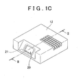
- Fig. 1C is a schematic perspective view depicting a main body part 12 of the connector case 10.
- the first embodiment is directed to a method for producing a connector case 10 in which a resin-made connector part (resin part) 14 is molded in an opening 20 of a metallic main body part 12 by using an injection molding process.
- the resin-made connector part 14 is molded onto the main body part 12 through an injection molding process. As is apparent in Figs. 1A and 1C , the connector part 14 is formed to block the opening 20 provided in the main body part 12.
- a foam sealant 16 is attached to an external surface of a peripheral portion (peripheral portion 21 shown in Fig. 1C ) around the opening 20 of the main body part 12.
- the connector part 14 is formed by injection-molding a resin.
- a retainer 18 indicated by broken lines serves to keep the foam sealant 16 compressed in its thickness direction prior to injection-molding the connector part 14.
- the term "thickness direction" refers to a direction extending from the sealant attachment surface in a height direction of the foam sealant.
- the retainer 18 is preferably formed with the same kind of resin as that of the injection-molded connector part 14. Thus, the retainer 18 becomes integrated with the injected molten resin to form a part of the connector part 14. It should be noted that the retainer 18 may be formed with any kind of resin as long as it can be integrated with the injected molten resin to form a part of the connector part 14.
- a metallic terminal 30 that functions to electrically interconnect an electrical component disposed within the main body part 12 and a cable of other connectors (not shown) coupled to the connector part 14.
- the junction area between the main body part 12 and the connector part 14 should be made air-tight.
- the foam sealant 16 serves to ensure the air-tightness.
- the foam sealant 16 is a sealant of high compressibility because it has previously been expanded.
- the term "high compressibility" means that the stress required in compressing the foam sealant is low.
- the foam sealant is of a type having characteristics that its compression ratio is not proportional to a compression stress and a high compression ratio can be obtained with a stress value smaller than that corresponding to the compression ratio. In other words, the foam sealant exhibits a narrow variation in stress in presence of a wide variation in strain. More specifically, it is preferred that the foam sealant 16 has a compression stress of equal to or smaller than 1.0x 10 -4 N/m 2 at a strain of 50 % , in its compression stress-strain characteristic measured by using a method in conformity with JISK6767. This is because, if the compression stress at a strain of 50% is equal to or smaller than 1.0x10 -4 N/m 2 , the foam sealant 16 can easily be compressed.
- Fig. 2 is a view showing a step of attaching the foam sealant 16 to the external surface of the peripheral portion 21 around the opening 20 of the main body part 12.
- Fig. 3 is a view illustrating a step of attaching the retainer 18 to the main body part 12 to keep the foam sealant 16 compressed in its thickness direction.
- Figs. 2 and 3 are enlarged vertical cross-sectional views taken along line II-II in Fig. 1C and showing the surroundings of the opening 20, in which those portions of the main body part 12 located more rearward than the paper plane are omitted from illustration.
- the foam sealant 16 is attached to the external surface of the peripheral portion 21 around the opening 20 of the main body part 12.
- the foam sealant 16 has a thickness of h1 in a load-free condition.
- the retainer 18 is attached to the main body part 12.
- the retainer 18 is formed of the same kind of resin as the resin part that is injection-molded later.
- the retainer 18 has a generally U-shaped cross section and keeps the foam sealant 16 compressed in its thickness direction by clamping together the foam sealant 16 attached to the main body part 12 and the peripheral portion 21 around the opening 20 of the main body part 12 one above the other in the thickness direction of the foam sealant 16.
- the retainer 18 is insertedly fitted through the opening 20 and comes in contact, at one end, with the surface of the foam sealant 16 attached to the main body part 12 and, at the other end, with the internal surface 19 of the peripheral portion 21 around the opening 20 of the main body part 12, thereby maintaining the foam sealant 16 compressed in the thickness direction.
- the retainer 18 compresses the foam sealant 16 to a thickness of h2.
- the value of h2 is smaller than the value of h1.
- the retainer 18 is adapted to keep the foam sealant 16 compressed in the thickness direction over the entire circumference of the opening 20.
- the retainer 18 may be configured to compress the foam sealant 16 in the thickness direction over at least a part of, preferably, one half of, the circumference of the opening 20.
- a plurality of retainers 18 may be used, in which case individual retainers may be disposed to, for example, compressingly clamp the foam sealant 16 on the four sides of the rectangular opening.
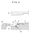
- FIGS. 4 through 8 Shown in Figs. 4 through 8 are vertical cross-sectional views taken along line II-II in Fig. 1C to illustrate the layout of components of the main body part 12 and a mold including a bottom mold 22, a top mold 24 and a slide mold 26.
- Fig. 4 shows the main body part 12 to which the retainer 18 for keeping the foam sealant 16 in a compressed condition is attached, i.e., the main body part 12 of the state illustrated in Fig. 3 , is disposed in the bottom mold 22. Also shown in Fig. 4 are the top mold 24 and the slide mold 26. When the main body part 12 is placed in the bottom mold 22, the top mold 24 and the slide mold 26 are kept in positions spaced apart from the bottom mold 22.
- the bottom mold 22 is provided with a resin injection passage 28.
- Fig. 5 shows the state in which a metallic terminal 30 is set in the bottom mold 22.
- the metallic terminal 30 is inserted through the opening 20 and extends through the main body part 12.
- the top mold 24 descends in the direction indicated by the arrow 32 and the slide mold 26 is moved in the direction indicated by the arrow 34 (in the right direction in Fig. 5 ).
- Fig. 6 illustrates the mold when it is closed.
- the top mold 24, the bottom mold 22, the slide mold 26 and a portion of the main body part 12 together to define a cavity 36 as illustrated in Fig. 6 .
- the main body part 12 is positioned within the mold in such a manner that, as depicted in Fig. 6 , the retainer 18 attached to the main body part 12 is exposed inside the cavity 36.
- the main body part 12 is located within the mold such that the internal surface (the surface designated by reference numeral 19 in Fig. 3 ) of the peripheral portion 21 around the opening 20 of the main body part 12 is exposed inside the cavity 36.
- Fig. 7 illustrates the cavity 36 when it is filled with the molten resin 40.
- the retainer 18 is made of the same kind of resin as the resin injected through the injection passage 28 and therefore the surface of the retainer 18 is melted by the heat of the molten resin 40 and becomes one with the molten resin 40 filled in the cavity 36. The condition is kept until the molten resin 40 is cooled down and becomes solidified.
- the foam sealant 16 is firmly compressed by the retainer 18 to seal the surface boundary between the main body part 12 and the molten resin 40.
- Figs. 7 and 8 the same resin part is designated by different reference numerals 14 and 40 and hatched in different directions in an effort to make clear that Fig. 7 shows the cavity 36 filled with the molten resin 40, while Fig. 8 illustrates the cavity 36 after the molten resin 40 has solidified to form the resin part 14. This numbering convention will also apply in other figures.
- the molten resin 40 is hatched with alternate thick and thin oblique lines running leftward and downward in Figs. 7 , 10 and 11 .
- the connector part (resin part) 14 formed through solidification of the molten resin 40 is hatched with alternate thick and thin oblique lines running rightward and downward in Figs. 1B , 8 , 12D and 13D .
- the retainer 18 is a component molded using the same kind of resin as the connector part 14, alternate thick and thin oblique lines running rightward and downward are used to hatch the retainer 18 as can be seen in Figs. 1B and 8 .
- the connector part 14 and the retainer 18 are all hatched with the same kind of alternate thick and thin oblique lines running rightward and downward.
- the molten resin is injected while the foam sealant 16 is compressed in the thickness direction . Since the retainer 18 is formed from the same resin as the injected molten resin, it becomes one with the molten resin to thereby form a part of the connector part (resin part) 14. This provides an air-tight seal between the retainer 18 and the injected resin.
- the foam sealant 16 is constantly kept compressed in the thickness direction by the retainer 18, allowing the required air-tightness to be secured between the resin-made connector part (resin part) 14 and the main body part 12 even though resin is injection-molded with respect to the main body part 12.
- This makes it possible to produce the connector case (molded article) 10 with the required air-tightness sustained between the resin-made connector part (resin part) 14 and the main body part 12 without performing an additional step to ensure the air-tightness between the connector part 14 and the main body part 12, after the resin has been injection-molded.
- the main body part 12 is located within the mold such that the internal surface 19 of the peripheral portion 21 around the opening 20 of the main body part 12 is exposed inside the cavity 36.
- the molten resin flowing through the opening 20 is filled into the cavity on the external surface side of the foam sealant 16 and the cavity on the internal surface side of the main body part 12.
- the resin part 14 thus injection-molded extends through the opening 20 and comes into a pressure-contact with the external surface of the foam sealant 16 and the internal surface of the main body part 12.
- the plurality of retainers for compressing the different sections of the foam sealant 16 around the opening 20 serve to prevent the foam sealant 16 from being dislocated from its original position. This ensures that the surface areas of the foam sealant 16 left out of contact with the plurality of retainers are sufficiently compressed between the molten resin and the main body part 12 in the thickness direction by the pressure of the injected molten resin, with no likelihood of dislocation from the originally attached position. If the molten resin shrinks while it is solidifying, the compressed foam sealant 16 expands to fill up the resulting gap, which makes it possible to assure the air-tightness.
- the molded article production method of the first embodiment includes the step whereby the retainer 18 for keeping the foam sealant 16 compressed in the thickness direction is attached to the main body part 12 before injection molding of the resin.
- the retainer 18 is designed to have a shape capable of keeping the foam sealant 16 compressed over the entire circumference thereof, it is possible to uniformly compress the foam sealant 16, attached around the periphery the opening 20 of the main body part 12, in its thickness direction.
- the retainer 18 is divided into a plurality of individual retainers capable of keeping the foam sealant 16 compressed at plural sections of the circumference thereof, it is possible for the respective retainers to prevent the foam sealant 16 from being dislocated on the sealant attachment surface when the foam sealant 16 is compressed by the pressure of the injected resin. This allows the foam sealant to be kept compressed in between the molten resin and the main body part. In either case, the required air-tightness can be secured at the surface boundary between the resin part and the main body part.
- the retainer 18 has a generally U-shaped cross section.
- the retainer 18 compresses the foam sealant 16 in its thickness direction by clamping the foam sealant 16, attached to the peripheral surface around the opening 20 of the main body part 12, and the main body part 12 together, one above the other, in the thickness direction of the foam sealant 16.
- the foam sealant 16 can be kept compressed in a reliable manner by designing the retainer 18 so as to clamp together the foam sealant 16 and the main body part 12.
- the retainer 18 is able to restrain the external surface and the inner circumferential surface of the foam sealant 16.
- the retainer 18 may have a shape capable of restraining the outer circumferential surface of the foam sealant 16, as well as the external surface and the inner circumferential surface thereof.
- the retainer 18 may be formed such that, when viewed in cross-section, the foam sealant 16 can be completely enclosed by the retainer 18 and the external surface of the main body part 12 to which the foam sealant 16 is attached. This makes it possible to efficiently compress the foam sealant 16 only in its thickness direction with no likelihood of dislocation on the sealant attachment surface. Compressing the foam sealant 16 only in its thickness direction further enhances the air-tightness between the resin-made connector part 14 and the main body part 12.
- the retainer 18 may have a shape adapted to clamp a thickness-reduced portion of the peripheral portion 21 around the opening 20 of the main body part 12 and the foam sealant 16 attached to the main body part 12, in its thickness direction.
- one or more lengthwise grooves are provided on the inner surface and/or the outer surface of the main body part 12 around the foam sealant 16 and one or more crosswise grooves are formed on the bottom of each of the lengthwise grooves. Then, the retainer 18 is pressed against the surface of the foam sealant 16 at one end and is hooked on the crosswise groove at the other end, allowing the retainer 18 to be latched to the main body part 12.
- Fig. 9 shows a closed mold in the second embodiment and corresponds to Fig. 6 , which was referred to when making description on the molded article production method of the first embodiment.
- Fig. 10 illustrates the cavity of the mold when the resin is injected in the second embodiment and corresponds to Fig. 7 , which was referred to when making description on the molded article production method of the first embodiment.
- the retainer 18 is not attached to the main body part 12.
- the main body part 12 of the condition as shown in Fig. 2 is disposed on the bottom mold 22 and, subsequently, the steps of the first embodiment illustrated in Figs. 4 and 5 are carried out.
- the top mold 24b includes a compression member 50a that can be moved within the cavity 36 in the thickness direction of the foam sealant 16, as can be seen in Fig. 9 .
- the slide mold 26 includes a compression member 50b that can be moved within the cavity 36 in the thickness direction of the foam sealant 16.
- the compression members 50a and 50b extend perpendicularly to the sealant attachment surface of the main body part 12. Referring to Fig. 9 , after the mold is closed, the compression member 50a is extended toward the foam sealant 16, located above the opening 20 in the figure. The extended compression member 50a compresses the foam sealant 16 located above the opening 20 .
- the compression member 50b is extended toward the foam sealant 16 located below the opening 20 in the figure.
- the extended compression member 50b compresses the foam sealant 16 located below the opening 20. Under this condition, molten resin is injected through the resin injection passage 28.
- the compression members 50a and 50b are retracted and separated from the foam sealant 16 before the injected resin solidifies. Since the injected resin 40 has not solidified, the empty spaces created by the retraction of the compression members 50a and 50b are filled with the resin 40 which is not solidified as yet. Subsequently, once the injected resin 40 is solidified, the mold is opened to remove the molded article in the same manner as set forth in the first embodiment with reference to Fig. 8 .
- the foam sealant 16 attached to around the opening 20 of the main body part 12 can be kept compressed in its thickness direction by means of the compression members 50a and 50b. This allows the foam sealant 16 to greatly improve air-tightness between the resin-made connector part 14 (see Fig. 8 ) and the main body part 12.
- the compressed foam sealant 16 is also expanded into the empty space left after retraction of the compression members 50a and 50b. However, the expansion of the foam sealant 16 is minimal, because the pressurized molten resin 40 of high fluidity fills the empty space faster than the foam sealant 16 can expand into the same. Moreover, the pressure of the molten resin 40 that fills the empty space maintains the compression of the foam sealant 16. The foam sealant 16 continues to be compressed by the compression members 50a and 50b until the molten resin 40 is fully charged around the foam sealant 16. This makes it possible to keep the foam sealant 16 substantially uniformly compressed in the surface boundary at the time when the resin-made connector part 14 has been molded.
- the compression members 50a and 50b are adapted to keep the foam sealant 16 compressed at the attached position until the injected molten resin fully arrives at the foam sealant 16 and its vicinities. This precludes the possibility that the molten resin is unevenly introduced to the side surfaces of the foam sealant 16 and thus the foam sealant 16 is dislocated from the originally attached position.
- those portions of the foam sealant 16 respectively located above and below the opening 20 in the drawings are kept compressed by means of the compression members 50a and 50b.
- the positions in which the foam sealant 16 is compressed by the compression members 50a and 50b are not restricted to the ones above and below the opening 20 in the drawings.
- the foam sealant 16 may be compressed in the left position and the right position of the opening 20.
- the surface areas of the foam sealant 16 left out of contact with the compression members 50a and 50b are compressed by the pressure of the injected molten resin, as described later in respect of the third embodiment.
- a first modified embodiment will be first set forth with reference to Fig. 11 which shows a step of the first modified embodiment corresponding to the step of the first embodiment illustrated in Fig. 7 .
- the top mold 24c is provided with a pressure-measuring unit 60 for measuring the pressure of the molten resin 40 injected into the cavity 36.
- the pressure measuring unit 60 includes a cylinder 62 communicating with the cavity 36, a piston 64 slidable with respect to the cylinder 62, a piston rod 66 fixedly secured to the piston 64 and a resilient member 68 for biasing the piston 64 toward the cavity 36.
- the pressure of the molten resin 40 raised the piston 64. Because the piston 64 is kept biased toward the cavity 36 by means of the resilient member 68, the piston 64 is moved upwardly into a position where the pressure of the molten resin 40 in the cavity 36 is balanced with the biasing force of the resilient member 68 applied to the piston 64. This means that the pressure of the molten resin 40 in the cavity 36 can be found by measuring the upward displacement of the piston rod 66 fixedly secured to the piston 64. The molten resin 40 is injected through the injection passage 28 at a predetermined pressure. Thus, measuring the pressure in the cavity 36 by use of the pressure measuring unit 60 makes it possible to determine whether or not the foam sealant 16 is in a normal condition.
- the pressure value in the cavity 36 measured by the pressure measuring unit 60 differs from a typical pressure value. Accordingly, the presence of the pressure measuring unit 60 makes it possible to detect that the easy-to-deform foam sealant 16 is in an abnormal condition. If the foam sealant 16 gets trapped in the surface boundary between the resin part 14 and the main body part 12, it cannot be judged by appearances whether or not the foam sealant 16 has been compressed in a proper manner. According to the first modified embodiment, the proper compression of the foam sealant 16 can be determined by use of the pressure measuring unit 60. This makes it possible to efficiently control the quality of the molded article produced through the use of the foam sealant 16 and having the resin part 14 integrally molded with the main body part 12.
- FIG. 12A is a schematic perspective view showing a main body part 12b employed in the second modified embodiment
- Fig. 12B is a view illustrating the state in which a foam sealant 16 is attached to the main body part 12b
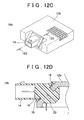
- Fig. 12C is a schematic perspective view showing a connector case 10b to which a connector part 14 has been molded
- Fig. 12D is an enlarged vertical cross-sectional view of the connector case 10b taken along line 12D-12D in Fig. 12C to illustrate the surroundings of an opening 20.
- the main body part 12b of the second modified embodiment is provided with a raised rim portion 70 around the opening 20 thereof.
- the connector case 10b is produced by integrally molding the resin-made connector part 14 to the main body part 12b having the raised rim portion 70.
- the area 21 lying inside the raised rim portion 70 of the main body part 12b serves as a target surface to which the foam sealant 16 is to be attached.
- the foam sealant 16 is attached to the target surface along the raised rim portion 70 provided around the opening 20 of the main body part 12b.
- the opening 20 of the main body part 12b is closed by means of the resin-made connector part 14 integrally molded with the main body part 12b.
- the foam sealant 16 extends along the raised rim portion 70 provided around the opening 20 and remains sealingly compressed in between the main body part 12b and the connector part 14. Keeping the foam sealant 16 in such a sealingly compressed condition ensures the air-tightness between the main body part 12b and the connector part 14.
- Other details of the method for producing the connector case 10b in this modified embodiment are substantially the same as fully set forth in respect of the methods of the first through third embodiments.
- the foam sealant 16 is attached to the target surface along the raised rim portion 70 provided around the opening 20 of the main body part 12b.
- the raised rim portion 70 can prevent the foam sealant 16 from being dislocated off its attachment surface when the resin is injected. This makes it possible to efficiently compress the foam sealant 16 in its thickness direction with no likelihood of dislocation on its attachment surface.
- the foam sealant 16 may be attached in such a manner as to go over the raised rim portion 70.
- FIG. 13A is a schematic perspective view showing a main body part 12c employed in the third modified embodiment
- Fig. 13B is a view illustrating the state in which a foam sealant 16 is attached to the main body part 12c
- Fig. 13C is a schematic perspective view showing a connector case 10c to which a connector part 14 has been molded
- Fig. 13D is an enlarged vertical cross-sectional view of the connector case 10c taken along line 13D-13D in Fig. 13C to illustrate the surroundings of an opening 20.
- the main body part 12c of the third modified embodiment is provided with a groove portion 72 around the opening 20 thereof.
- the connector case 10c is produced by integrally molding the resin-made connector part 14 to the main body part 12c having the groove portion 72.
- the foam sealant 16 is attached to the bottom surface of the groove portion 72 of the main body part 12b.
- the opening 20 of the main body part 12c is closed up by means of the resin-made connector part 14 integrally molded with the main body part 12c.
- the foam sealant 16 extends along the groove portion 72 provided around the opening 20 and remains sealingly compressed in between the main body part 12c and the connector part 14. Keeping the foam sealant 16 in such a sealingly compressed condition ensures the air-tightness between the main body part 12c and the connector part 14.
- Other details of the method for producing the connector case 10c in this modified embodiment are substantially the same as fully set forth in respect of the methods of the first through third embodiments.
- the foam sealant 16 is attached to the bottom surface of the groove portion 72 provided around the opening 20 of the main body part 12c. Attaching the foam sealant 16 on the bottom surface of the groove portion 72 can prevent the foam sealant 16 from being dislocated on its attachment surface when the resin is injected. This makes it possible to efficiently compress the foam sealant 16 in its thickness direction and reduces the likelihood of dislocation on its attachment surface.
- the groove portion 72 may have a cross-section of rectangular or sector-like shape. Moreover, the foam sealant 16 may be partially disposed in the groove portion 72.
- a liquid or powdery sealant containing an expandable substance can also be used in place of the foam sealant.
- each of the molded article production methods may instead incorporate a step of applying the liquid or powdery sealant containing an expandable substance on the peripheral portion around the opening of the main body part and a step of foaming the expandable substance contained in the sealant thus applied.
- the resin part is injection-molded to the main body part using the same steps as described above in connection with the embodiments and modified embodiments. This also makes it possible to produce a molded article that provides an excellent air-tightness between the resin part and the main body part.
- the step of applying the liquid or powdery sealant containing an expandable substance is suitable for machine-based automation.
- a molded article ensuring excellent air-tightness between the resin part and the main body part can be produced by means of an automated production method.
- the foam sealant preferably has a compression ratio that is at least equal to or greater than 5% when the injected resin solidifies. If the foam sealant 16 is kept compressed at least 5% or more at the surface boundary between the resin part and the main body part, the required level of air-tightness can be easily maintained.
- the foam sealant has a compression ratio of about 90% at the time when the injected resin is not in a solid state.
- the reason for keeping the compression ratio of the foam sealant equal to about 90% prior to the solidification of the injected resin is that the post-resin-solidification compression ratio of the foam sealant becomes at least 5% or more, thus maintaining the air-tightness in the surface boundary, even when the compressed foam sealant expands and fills up into the gap created by the solidification and shrinkage of the resin.
- the foam sealant is attached to the external surface around the opening of the main body part.
- the foam sealant may be attached to the inner circumference of the opening 20.
- the form sealant may be attached to the internal surface around the opening of the main body part.
- the molded articles produced using the above-described production methods include a resin part that is injection-molded into an opening of the main body part.
- a foam sealant is attached to the peripheral surface of the opening of the main body part.
- the injection-molded resin part extends through the opening and makes contact, at its outer body side, with a surface of the foam sealant and, at its inner body side, with the internal surface 19 of the main body part 12, thus compressing the foam sealant in the thickness direction at a compression ratio of 5%-90%.
- additional foam sealant may be attached to the internal surface of the peripheral portion around the opening 20 of the main body part 12, allowing the resin part 14 to come into a contact at its inner body side with the internal surface of the main body part through the additional foam sealant.
- the foam sealant compressed at a compression ratio of 5%-90% is inserted between the main body part and the resin part, thereby ensuring the air-tightness at the surface boundary of the main body part 12 and the resin part 14.
- the injection-molded resin part 14 extends through the opening 20 to make pressure-contact with the external surface of the foam sealant and, at the same time, with the internal surface of the main body part.
- the foam sealant is compressed at its internal and external surfaces by the resin part and therefore can be kept compressed for an extended period of time.
- the present invention provides the following advantageous effects, which are attributable to the attachment of the foam sealant to the main body part before injection-molding a resin part:
- a metallic connector case is used as an example of the main body part for the molded article in which a resin part is injection-molded to the main body part.
- the molded article to which the present invention relates is not confined to a connector case.
- the material of which the main body part is made is not restricted to metal but may include, for example, a resin material that has a higher melting point than that of the injection-molded resin part.
Landscapes
- Engineering & Computer Science (AREA)
- Manufacturing & Machinery (AREA)
- Mechanical Engineering (AREA)
- Injection Moulding Of Plastics Or The Like (AREA)
- Moulds For Moulding Plastics Or The Like (AREA)
- Manufacturing Of Electrical Connectors (AREA)
- Casting Or Compression Moulding Of Plastics Or The Like (AREA)
Claims (8)
- Verfahren zum Herstellen eines gegossenen Artikels, in dem ein Harzteil (14) in eine Öffnung (20) eines Hauptkörperteils (12; 12b; 12c) spritzgegossen wird, wobei das Verfahren die folgenden Schritte aufweist:Anbringen eines Schaumdichtungsmittels (16) an einem Seitenabschnitt um die Öffnung (20) des Hauptkörperteils (12; 12b; 12c);Anbringen eines Klemmrings (18) an das Hauptkörperteil (12; 12b;
12c), so dass der Klemmring (18) das Schaumdichtungsmittel (16), das an dem Hauptkörperteil (12; 12b; 12c) angebracht ist, und den seitlichen Abschnitt um die Öffnung (20) des Hauptkörperteils (12; 12b; 12c) zusammen in eine Dickenrichtung des Schaumdichtungsmittels (16) klemmt, um dadurch das Schaumdichtungsmittel (16) in die Dickenrichtung zusammenzupressen;Kombinieren des Hauptkörperteils (12; 12b; 12c) mit einer Gussform (22, 24, 26; 24c), um einen Hohlraum (36) auszubilden, in dem der Klemmring (18), der an dem Hauptkörperteil (12; 12b; 12c) angebracht ist, innerhalb des Hohlraums (36) offengelegt ist; undEinspritzen eines geschmolzenen Harzes in den Hohlraum (36). - Verfahren nach Anspruch 1, wobei der Klemmring (18) aus der gleichen Harzart hergestellt ist wie das eingespritzte Harz.
- Verfahren zum Herstellen eines gegossenen Artikels, in dem ein Harzteil (14) in eine Öffnung (20) eines Hauptkörperteils (12; 12b; 12c) spritzgegossen wird, wobei das Verfahren die folgenden Schritte aufweist:Anbringen eines Schaumdichtungsmittels (16) an einen Seitenabschnitt um die Öffnung (20) des Hauptkörperteils (12; 12b; 12c);Kombinieren des Hauptkörperteils (12; 12b; 12c) mit einer Gussform (22, 24b, 26b), um einen Hohlraum (36) auszubilden, in dem das Schaumdichtungsmittel (16), das an dem Hauptkörperteil (12; 12b; 12c) angebracht ist, und der Seitenabschnitt um die Öffnung (20) des Hauptkörperteils (12; 12b; 12c) innerhalb des Hohlraums (36) offengelegt sind;Bewegen eines Zusammenpresselements (50a, 50b), das bezüglich der Gussform (24b, 26b) gegen das Schaumdichtungsmittel (16) in eine Dickenrichtung des Schaumdichtungsmittels (12; 12b; 12c) bewegbar ist, um das Schaumdichtungsmittel (16) zusammenzupressen;Einspritzen eines geschmolzenen Harzes in den Hohlraum (36);
undTrennen des Zusammenpresselements (50a, 50b) von dem Schaumdichtungsmittel (36), bevor das eingespritzte, geschmolzene Harz sich verfestigt. - Verfahren nach einem der Ansprüche 1 bis 3, wobei in dem Schaumdichtungsmittelanbringschritt das Schaumdichtungsmittel (16) an eine Außenfläche des Seitenabschnitts um die Öffnung (20) des Hauptkörperteils (12; 12b; 12c) angebracht wird und wobei in dem den Hohlraum bestimmenden Schritt der Hohlraum (36) bestimmt wird, indem das Hauptkörperteil (12; 12b; 12c) mit der Gussform (22, 24, 26; 24b, 26b; 24c) kombiniert wird, so dass eine Innenfläche des Seitenabschnitts um die Öffnung (20) des Hauptkörperteils (12; 12b; 12c) innerhalb des Hohlraums (36) offengelegt ist.
- Verfahren nach einem der Ansprüche 1 bis 4, wobei bei dem Dichtungsmittelanbringschritt das Schaumdichtungsmittel (16) entlang eines erhobenen Randabschnitts (70) angebracht wird, der um die Öffnung (20) des Hauptkörperteils (12b) vorgesehen ist.
- Verfahren nach einem der Ansprüche 1 bis 4, wobei bei dem Dichtungsmittelanbringschritt das Schaumdichtungsmittel (16) an einen Nutabschnitt (72) angebracht wird, der um die Öffnung (20) des Hauptkörperteils (12c) vorgesehen ist.
- Verfahren nach einem der Ansprüche 1 bis 6, wobei bei dem Schaumdichtungsmittelanbringschritt ein flüssiges oder pulvriges Dichtungsmittel mit einer sich ausdehnenden Substanz auf den Seitenabschnitt um die Öffnung (20) des Hauptkörperteils (12; 12b; 12c) verteilt wird und anschließend dieses flüssige oder pulvrige Dichtungsmittel expandiert wird.
- Gegossener Artikel, der in Übereinstimmung mit dem Verfahren nach einem der vorhergehenden Ansprüche hergestellt worden ist, mit dem Hauptkörperteil (12; 12b; 12c), das darauf das Harzteil (14) einheitlich spritzgegossen mit dem Klemmring (18) hat, und dem Schaumdichtungsmittel (16), das an dem Seitenabschnitt um die Öffnung (20) des Hauptkörperteils (12; 12b; 12c) angebracht ist.
Applications Claiming Priority (1)
| Application Number | Priority Date | Filing Date | Title |
|---|---|---|---|
| JP2005334112A JP4758205B2 (ja) | 2005-11-18 | 2005-11-18 | 成形体の製造方法 |
Publications (3)
| Publication Number | Publication Date |
|---|---|
| EP1787783A2 EP1787783A2 (de) | 2007-05-23 |
| EP1787783A3 EP1787783A3 (de) | 2008-03-19 |
| EP1787783B1 true EP1787783B1 (de) | 2013-09-04 |
Family
ID=37772629
Family Applications (1)
| Application Number | Title | Priority Date | Filing Date |
|---|---|---|---|
| EP06255801.0A Not-in-force EP1787783B1 (de) | 2005-11-18 | 2006-11-13 | Verfahren zur Herstellung eines spritzgegossenen Artikels und danach hergestellter Artikel |
Country Status (4)
| Country | Link |
|---|---|
| US (1) | US8038914B2 (de) |
| EP (1) | EP1787783B1 (de) |
| JP (1) | JP4758205B2 (de) |
| CN (1) | CN100546803C (de) |
Families Citing this family (11)
| Publication number | Priority date | Publication date | Assignee | Title |
|---|---|---|---|---|
| JP5038412B2 (ja) * | 2007-11-29 | 2012-10-03 | 日本特殊陶業株式会社 | 金属樹脂複合体 |
| JP4567764B2 (ja) * | 2008-04-03 | 2010-10-20 | トヨタ紡織株式会社 | 接合方法 |
| KR20100010598A (ko) * | 2008-07-23 | 2010-02-02 | 삼성전자주식회사 | 화상형성장치용 일체형 실링 부재 및 이를 형성하는 방법 |
| FR2953158B1 (fr) * | 2009-11-30 | 2012-01-20 | Airbus Operations Sas | Procede pour realiser une jonction etanche entre des pieces d'aeronef |
| US8377368B2 (en) * | 2009-12-11 | 2013-02-19 | Ti Automotive Technology Center Gmbh | Component mounting arrangement |
| JP5580116B2 (ja) * | 2010-06-07 | 2014-08-27 | 矢崎総業株式会社 | 射出成形による樹脂成形品の製造方法 |
| JP5776856B2 (ja) * | 2012-11-09 | 2015-09-09 | 日本精工株式会社 | コネクタ |
| JP2014154344A (ja) * | 2013-02-08 | 2014-08-25 | Hitachi Metals Ltd | コネクタ支持構造及びコネクタ付き電子装置 |
| JP6211306B2 (ja) * | 2013-05-23 | 2017-10-11 | ダイキョーニシカワ株式会社 | 電磁波遮蔽容器 |
| JP6324528B2 (ja) * | 2014-11-13 | 2018-05-16 | 三菱電機株式会社 | 防水型制御ユニットの製造方法 |
| DE102017212971A1 (de) | 2017-07-27 | 2019-01-31 | Robert Bosch Gmbh | Montageelement, Montagesatz, Verfahren zum Montieren und Bauteil |
Family Cites Families (27)
| Publication number | Priority date | Publication date | Assignee | Title |
|---|---|---|---|---|
| US4011819A (en) * | 1976-03-03 | 1977-03-15 | The United States Of America As Represented By The Secretary Of The Navy | Stress relieved molded cover assembly and method of making the same |
| US4083902A (en) * | 1977-01-10 | 1978-04-11 | Raychem Corporation | Method of sealing a connector |
| DE3885858T2 (de) * | 1987-06-13 | 1994-03-17 | Tdk Corp | Wasserdichte elektrodenanschluss-vorrichtung für lebende organismen. |
| CA1328158C (en) * | 1988-05-11 | 1994-04-05 | Toshiyuki Kanai | Multi-injection molded body, a method of molding for the same, and a multi-injection molding machine |
| FR2646800A1 (fr) * | 1989-05-12 | 1990-11-16 | Mgi Coutiers | Procede pour realiser en matiere plastique opaque des boites a eau presentant une fenetre de lecture de niveau, et boites a eau obtenues |
| US5122858A (en) * | 1990-09-10 | 1992-06-16 | Olin Corporation | Lead frame having polymer coated surface portions |
| US5098801A (en) * | 1990-09-12 | 1992-03-24 | General Motors Corporation | Bipolar battery and assembly method |
| DE4125324A1 (de) * | 1991-07-31 | 1993-02-04 | Bopla Gehaeuse Systeme Gmbh | Verfahren zum herstellen einer wandung, insbesondere eines gehaeuses mit sichtfenster |
| US5588856A (en) * | 1991-09-18 | 1996-12-31 | Raychem Corporation | Sealing member and methods of sealing |
| US5271880A (en) * | 1992-06-09 | 1993-12-21 | Illinois Tool Works Inc. | Insert molding method for a seal member |
| US5447446A (en) * | 1992-11-05 | 1995-09-05 | Thomas & Betts Corporation | Electrical connector component having secured seal |
| US5690881A (en) * | 1994-05-13 | 1997-11-25 | Nippondenso Co., Ltd. | Manufacturing method of resin damper having foamed resin seal material |
| US5792407A (en) * | 1996-03-18 | 1998-08-11 | Berzack; Jeffrey A. | Method for attaching flexible, low density or compressible structures to injection molded polymer parts |
| DE19615371C2 (de) * | 1996-04-19 | 1998-09-10 | Schott Glaswerke | Formkörper aus Glas oder Glaskeramik, eingefaßt in einem umspritzten Kunststoff-Halterahmen und Verfahren zum Einfassen des Formkörpers mit dem Halterahmen |
| JPH1015985A (ja) | 1996-06-28 | 1998-01-20 | Nippon Petrochem Co Ltd | 金属部材をインサートした樹脂成形体およびその製造方法 |
| JP3046550B2 (ja) * | 1996-08-29 | 2000-05-29 | 東海興業株式会社 | ケース一体コネクタ、及びその成形方法 |
| US6500027B1 (en) * | 1997-01-28 | 2002-12-31 | Ludovicus Cornelis Van Der Sanden | Seal for an electrical connector, method for manufacturing a seal and use of a seal |
| JPH10223301A (ja) * | 1997-02-07 | 1998-08-21 | Yazaki Corp | 防水コネクタハウジング、及びその製造方法、並びに防水コネクタハウジング成形用金型 |
| JPH1138024A (ja) * | 1997-07-22 | 1999-02-12 | Toyota Motor Corp | 金属部材と樹脂部材との間のシール構造 |
| US20020004128A1 (en) * | 1998-05-28 | 2002-01-10 | Anthony Forte | Method and system for sealing electrical connection using sealant-impregnated foam |
| DE19961233C1 (de) * | 1999-12-18 | 2001-03-15 | Meritor Automotive Gmbh | Verfahren zum Abdichten von Steckverbindungselementen elektrischer Leitungssysteme beim Einschäumen in Bauteile und dabei einzusetzende Vorrichtungen |
| JP2002134219A (ja) * | 2000-10-30 | 2002-05-10 | Yazaki Corp | 防水コネクタ及び該防水コネクタの製造方法 |
| US20030194896A1 (en) * | 2002-04-15 | 2003-10-16 | Fetcenko Richard M. | Gasket |
| JP2004088989A (ja) * | 2002-07-03 | 2004-03-18 | Auto Network Gijutsu Kenkyusho:Kk | 電力回路部の防水方法 |
| US7390845B2 (en) * | 2002-07-26 | 2008-06-24 | Illinois Tool Works Inc | Sealing system and process therefor |
| US6926856B2 (en) * | 2002-07-29 | 2005-08-09 | Dow Global Technologies Inc. | Molded parts with fabric surface areas and processes for their production |
| US6913493B2 (en) * | 2003-11-05 | 2005-07-05 | Molex Incorporated | Sealed electrical connector assembly and method of fabricating same |
-
2005
- 2005-11-18 JP JP2005334112A patent/JP4758205B2/ja not_active Expired - Fee Related
-
2006
- 2006-11-06 US US11/592,961 patent/US8038914B2/en not_active Expired - Fee Related
- 2006-11-13 EP EP06255801.0A patent/EP1787783B1/de not_active Not-in-force
- 2006-11-17 CN CNB2006101485151A patent/CN100546803C/zh not_active Expired - Fee Related
Also Published As
| Publication number | Publication date |
|---|---|
| CN100546803C (zh) | 2009-10-07 |
| CN1966237A (zh) | 2007-05-23 |
| JP4758205B2 (ja) | 2011-08-24 |
| EP1787783A3 (de) | 2008-03-19 |
| JP2007136868A (ja) | 2007-06-07 |
| EP1787783A2 (de) | 2007-05-23 |
| US8038914B2 (en) | 2011-10-18 |
| US20070120287A1 (en) | 2007-05-31 |
Similar Documents
| Publication | Publication Date | Title |
|---|---|---|
| US8038914B2 (en) | Molded article production method and molded article | |
| CN101124075B (zh) | 埋设构件成形体的制造方法 | |
| US9028737B2 (en) | Method for producing resin molded article by injection molding, and injection molding device | |
| US20250389966A1 (en) | Low pressure molded article and method for making same | |
| KR100186841B1 (ko) | 성형 장치 및 성형 방법 | |
| JP2002527264A (ja) | 射出成形されたエラストマシールを備えた熱可塑性部分の製作方法 | |
| JP3585854B2 (ja) | 射出成形方法 | |
| US6340791B1 (en) | Means and process for encapsulating electric circuits by means of injection molding | |
| CN108162302B (zh) | 一种注塑件及其注塑成型方法、防水设备 | |
| EP0371773A2 (de) | Fenster für Kraftfahrzeuge und deren Herstellungsverfahren | |
| JPH0976282A (ja) | 電気・電子部品の樹脂封止成形方法及びそれに用いる金型 | |
| KR100531219B1 (ko) | 터미널 삽입형 성형물의 사출성형방법 및 성형물 삽입용터미널 | |
| TAKEDA et al. | Development of High Productivity and Low Cost card-edge Type ECU for Motorcycles | |
| JP7369345B2 (ja) | 金属フォームのための成形プロセス、装置、及び製品 | |
| US20210183538A1 (en) | Mechanical stress isolation conductors in lead frames | |
| JPH07142278A (ja) | 内包ボビンの封止成形方法及び内包ボビンの封止成形部品を形成する封止成形用金型 | |
| JP2674037B2 (ja) | ガスケット付き窓ガラスの製造法 | |
| JP4368799B2 (ja) | 複合射出成形方法並びに金型 | |
| KR101587710B1 (ko) | 라디에이터 박스 또는 인터쿨러 박스의 제조 방법 | |
| CN217123835U (zh) | 一种用于注塑带电缆零件的模具 | |
| JPS63151413A (ja) | インサ−トの埋設された発泡成形品の製造方法 | |
| JPH0824991A (ja) | 鋳造方法及びその方法で使用される中子 | |
| JP2017222122A (ja) | 樹脂成形部材の成形方法及び成形システム | |
| JP2001246648A (ja) | インサート・アウトサート成形金型 | |
| JPH07201435A (ja) | 樹脂充填コネクタの製造方法 |
Legal Events
| Date | Code | Title | Description |
|---|---|---|---|
| PUAI | Public reference made under article 153(3) epc to a published international application that has entered the european phase |
Free format text: ORIGINAL CODE: 0009012 |
|
| 17P | Request for examination filed |
Effective date: 20061130 |
|
| AK | Designated contracting states |
Kind code of ref document: A2 Designated state(s): AT BE BG CH CY CZ DE DK EE ES FI FR GB GR HU IE IS IT LI LT LU LV MC NL PL PT RO SE SI SK TR |
|
| AX | Request for extension of the european patent |
Extension state: AL BA HR MK YU |
|
| PUAL | Search report despatched |
Free format text: ORIGINAL CODE: 0009013 |
|
| AK | Designated contracting states |
Kind code of ref document: A3 Designated state(s): AT BE BG CH CY CZ DE DK EE ES FI FR GB GR HU IE IS IT LI LT LU LV MC NL PL PT RO SE SI SK TR |
|
| AX | Request for extension of the european patent |
Extension state: AL BA HR MK YU |
|
| AKX | Designation fees paid |
Designated state(s): DE FR GB |
|
| 17Q | First examination report despatched |
Effective date: 20100824 |
|
| GRAP | Despatch of communication of intention to grant a patent |
Free format text: ORIGINAL CODE: EPIDOSNIGR1 |
|
| RAP1 | Party data changed (applicant data changed or rights of an application transferred) |
Owner name: TOYOTA JIDOSHA KABUSHIKI KAISHA Owner name: MATSUO INDUSTRIES INC. |
|
| GRAS | Grant fee paid |
Free format text: ORIGINAL CODE: EPIDOSNIGR3 |
|
| GRAA | (expected) grant |
Free format text: ORIGINAL CODE: 0009210 |
|
| AK | Designated contracting states |
Kind code of ref document: B1 Designated state(s): DE FR GB |
|
| REG | Reference to a national code |
Ref country code: GB Ref legal event code: FG4D |
|
| REG | Reference to a national code |
Ref country code: DE Ref legal event code: R096 Ref document number: 602006038200 Country of ref document: DE Effective date: 20131031 |
|
| REG | Reference to a national code |
Ref country code: DE Ref legal event code: R097 Ref document number: 602006038200 Country of ref document: DE |
|
| PLBE | No opposition filed within time limit |
Free format text: ORIGINAL CODE: 0009261 |
|
| STAA | Information on the status of an ep patent application or granted ep patent |
Free format text: STATUS: NO OPPOSITION FILED WITHIN TIME LIMIT |
|
| 26N | No opposition filed |
Effective date: 20140605 |
|
| REG | Reference to a national code |
Ref country code: DE Ref legal event code: R097 Ref document number: 602006038200 Country of ref document: DE Effective date: 20140605 |
|
| REG | Reference to a national code |
Ref country code: FR Ref legal event code: PLFP Year of fee payment: 10 |
|
| PGFP | Annual fee paid to national office [announced via postgrant information from national office to epo] |
Ref country code: DE Payment date: 20151110 Year of fee payment: 10 Ref country code: GB Payment date: 20151111 Year of fee payment: 10 |
|
| PGFP | Annual fee paid to national office [announced via postgrant information from national office to epo] |
Ref country code: FR Payment date: 20151008 Year of fee payment: 10 |
|
| REG | Reference to a national code |
Ref country code: DE Ref legal event code: R119 Ref document number: 602006038200 Country of ref document: DE |
|
| GBPC | Gb: european patent ceased through non-payment of renewal fee |
Effective date: 20161113 |
|
| REG | Reference to a national code |
Ref country code: FR Ref legal event code: ST Effective date: 20170731 |
|
| PG25 | Lapsed in a contracting state [announced via postgrant information from national office to epo] |
Ref country code: FR Free format text: LAPSE BECAUSE OF NON-PAYMENT OF DUE FEES Effective date: 20161130 |
|
| PG25 | Lapsed in a contracting state [announced via postgrant information from national office to epo] |
Ref country code: GB Free format text: LAPSE BECAUSE OF NON-PAYMENT OF DUE FEES Effective date: 20161113 Ref country code: DE Free format text: LAPSE BECAUSE OF NON-PAYMENT OF DUE FEES Effective date: 20170601 |