EP1768459A1 - Elément chauffant d'un dispositif de chauffage - Google Patents
Elément chauffant d'un dispositif de chauffage Download PDFInfo
- Publication number
- EP1768459A1 EP1768459A1 EP06017063A EP06017063A EP1768459A1 EP 1768459 A1 EP1768459 A1 EP 1768459A1 EP 06017063 A EP06017063 A EP 06017063A EP 06017063 A EP06017063 A EP 06017063A EP 1768459 A1 EP1768459 A1 EP 1768459A1
- Authority
- EP
- European Patent Office
- Prior art keywords
- heat
- generating element
- frame
- element according
- insulating layer
- Prior art date
- Legal status (The legal status is an assumption and is not a legal conclusion. Google has not performed a legal analysis and makes no representation as to the accuracy of the status listed.)
- Granted
Links
- 238000010438 heat treatment Methods 0.000 title claims description 29
- 238000007789 sealing Methods 0.000 claims abstract description 61
- 239000011324 bead Substances 0.000 claims abstract description 54
- 239000004020 conductor Substances 0.000 claims abstract description 26
- 239000004033 plastic Substances 0.000 claims abstract description 22
- 229920003023 plastic Polymers 0.000 claims abstract description 22
- 239000000919 ceramic Substances 0.000 claims description 17
- 229910052751 metal Inorganic materials 0.000 claims description 14
- 239000002184 metal Substances 0.000 claims description 14
- 238000005538 encapsulation Methods 0.000 claims description 13
- 238000003825 pressing Methods 0.000 claims description 2
- 230000000284 resting effect Effects 0.000 claims 1
- 239000010410 layer Substances 0.000 description 113
- 239000000463 material Substances 0.000 description 16
- 238000004519 manufacturing process Methods 0.000 description 11
- 239000000853 adhesive Substances 0.000 description 10
- 230000001070 adhesive effect Effects 0.000 description 10
- 229920001296 polysiloxane Polymers 0.000 description 8
- 210000002105 tongue Anatomy 0.000 description 8
- 125000006850 spacer group Chemical group 0.000 description 7
- 238000011161 development Methods 0.000 description 5
- 230000018109 developmental process Effects 0.000 description 5
- 238000001746 injection moulding Methods 0.000 description 5
- 239000002985 plastic film Substances 0.000 description 5
- 229920006255 plastic film Polymers 0.000 description 5
- 230000015556 catabolic process Effects 0.000 description 4
- 238000010292 electrical insulation Methods 0.000 description 4
- 238000002347 injection Methods 0.000 description 4
- 239000007924 injection Substances 0.000 description 4
- TWNQGVIAIRXVLR-UHFFFAOYSA-N oxo(oxoalumanyloxy)alumane Chemical compound O=[Al]O[Al]=O TWNQGVIAIRXVLR-UHFFFAOYSA-N 0.000 description 4
- 238000004026 adhesive bonding Methods 0.000 description 3
- 239000002775 capsule Substances 0.000 description 3
- 229920001971 elastomer Polymers 0.000 description 3
- 239000000806 elastomer Substances 0.000 description 3
- 238000009413 insulation Methods 0.000 description 3
- 229910000679 solder Inorganic materials 0.000 description 3
- 230000008719 thickening Effects 0.000 description 3
- 239000004952 Polyamide Substances 0.000 description 2
- 230000008901 benefit Effects 0.000 description 2
- 230000015572 biosynthetic process Effects 0.000 description 2
- 238000005520 cutting process Methods 0.000 description 2
- 230000000694 effects Effects 0.000 description 2
- 239000000155 melt Substances 0.000 description 2
- 238000002844 melting Methods 0.000 description 2
- 230000008018 melting Effects 0.000 description 2
- 238000000034 method Methods 0.000 description 2
- 238000013021 overheating Methods 0.000 description 2
- 229920002647 polyamide Polymers 0.000 description 2
- 229920002635 polyurethane Polymers 0.000 description 2
- 239000004814 polyurethane Substances 0.000 description 2
- 238000012545 processing Methods 0.000 description 2
- 239000013464 silicone adhesive Substances 0.000 description 2
- 239000000243 solution Substances 0.000 description 2
- 238000012546 transfer Methods 0.000 description 2
- 239000012790 adhesive layer Substances 0.000 description 1
- 229910052782 aluminium Inorganic materials 0.000 description 1
- XAGFODPZIPBFFR-UHFFFAOYSA-N aluminium Chemical compound [Al] XAGFODPZIPBFFR-UHFFFAOYSA-N 0.000 description 1
- PNEYBMLMFCGWSK-UHFFFAOYSA-N aluminium oxide Inorganic materials [O-2].[O-2].[O-2].[Al+3].[Al+3] PNEYBMLMFCGWSK-UHFFFAOYSA-N 0.000 description 1
- 150000001875 compounds Chemical class 0.000 description 1
- 230000006835 compression Effects 0.000 description 1
- 238000007906 compression Methods 0.000 description 1
- 238000011109 contamination Methods 0.000 description 1
- 238000001816 cooling Methods 0.000 description 1
- 238000006731 degradation reaction Methods 0.000 description 1
- 239000011888 foil Substances 0.000 description 1
- 239000007789 gas Substances 0.000 description 1
- 230000017525 heat dissipation Effects 0.000 description 1
- 238000012432 intermediate storage Methods 0.000 description 1
- 238000012986 modification Methods 0.000 description 1
- 230000004048 modification Effects 0.000 description 1
- 239000002991 molded plastic Substances 0.000 description 1
- 238000012856 packing Methods 0.000 description 1
- 230000000149 penetrating effect Effects 0.000 description 1
- 230000036316 preload Effects 0.000 description 1
- 230000001105 regulatory effect Effects 0.000 description 1
- 230000008439 repair process Effects 0.000 description 1
- 239000000565 sealant Substances 0.000 description 1
- 239000012945 sealing adhesive Substances 0.000 description 1
- 229920002379 silicone rubber Polymers 0.000 description 1
- 239000004945 silicone rubber Substances 0.000 description 1
- 239000012815 thermoplastic material Substances 0.000 description 1
- 230000007704 transition Effects 0.000 description 1
Images


Classifications
-
- H—ELECTRICITY
- H05—ELECTRIC TECHNIQUES NOT OTHERWISE PROVIDED FOR
- H05B—ELECTRIC HEATING; ELECTRIC LIGHT SOURCES NOT OTHERWISE PROVIDED FOR; CIRCUIT ARRANGEMENTS FOR ELECTRIC LIGHT SOURCES, IN GENERAL
- H05B3/00—Ohmic-resistance heating
- H05B3/40—Heating elements having the shape of rods or tubes
- H05B3/42—Heating elements having the shape of rods or tubes non-flexible
- H05B3/48—Heating elements having the shape of rods or tubes non-flexible heating conductor embedded in insulating material
- H05B3/50—Heating elements having the shape of rods or tubes non-flexible heating conductor embedded in insulating material heating conductor arranged in metal tubes, the radiating surface having heat-conducting fins
-
- F—MECHANICAL ENGINEERING; LIGHTING; HEATING; WEAPONS; BLASTING
- F24—HEATING; RANGES; VENTILATING
- F24H—FLUID HEATERS, e.g. WATER OR AIR HEATERS, HAVING HEAT-GENERATING MEANS, e.g. HEAT PUMPS, IN GENERAL
- F24H3/00—Air heaters
- F24H3/02—Air heaters with forced circulation
- F24H3/04—Air heaters with forced circulation the air being in direct contact with the heating medium, e.g. electric heating element
- F24H3/0405—Air heaters with forced circulation the air being in direct contact with the heating medium, e.g. electric heating element using electric energy supply, e.g. the heating medium being a resistive element; Heating by direct contact, i.e. with resistive elements, electrodes and fins being bonded together without additional element in-between
- F24H3/0429—For vehicles
- F24H3/0435—Structures comprising heat spreading elements in the form of fins
-
- F—MECHANICAL ENGINEERING; LIGHTING; HEATING; WEAPONS; BLASTING
- F24—HEATING; RANGES; VENTILATING
- F24H—FLUID HEATERS, e.g. WATER OR AIR HEATERS, HAVING HEAT-GENERATING MEANS, e.g. HEAT PUMPS, IN GENERAL
- F24H3/00—Air heaters
- F24H3/02—Air heaters with forced circulation
- F24H3/04—Air heaters with forced circulation the air being in direct contact with the heating medium, e.g. electric heating element
- F24H3/0405—Air heaters with forced circulation the air being in direct contact with the heating medium, e.g. electric heating element using electric energy supply, e.g. the heating medium being a resistive element; Heating by direct contact, i.e. with resistive elements, electrodes and fins being bonded together without additional element in-between
- F24H3/0429—For vehicles
- F24H3/0441—Interfaces between the electrodes of a resistive heating element and the power supply means
- F24H3/0447—Forms of the electrode terminals, e.g. tongues or clips
-
- F—MECHANICAL ENGINEERING; LIGHTING; HEATING; WEAPONS; BLASTING
- F24—HEATING; RANGES; VENTILATING
- F24H—FLUID HEATERS, e.g. WATER OR AIR HEATERS, HAVING HEAT-GENERATING MEANS, e.g. HEAT PUMPS, IN GENERAL
- F24H3/00—Air heaters
- F24H3/02—Air heaters with forced circulation
- F24H3/04—Air heaters with forced circulation the air being in direct contact with the heating medium, e.g. electric heating element
- F24H3/0405—Air heaters with forced circulation the air being in direct contact with the heating medium, e.g. electric heating element using electric energy supply, e.g. the heating medium being a resistive element; Heating by direct contact, i.e. with resistive elements, electrodes and fins being bonded together without additional element in-between
- F24H3/0429—For vehicles
- F24H3/0452—Frame constructions
- F24H3/0464—Two-piece frames, e.g. two-shell frames, also including frames as a central body with two covers
-
- F—MECHANICAL ENGINEERING; LIGHTING; HEATING; WEAPONS; BLASTING
- F24—HEATING; RANGES; VENTILATING
- F24H—FLUID HEATERS, e.g. WATER OR AIR HEATERS, HAVING HEAT-GENERATING MEANS, e.g. HEAT PUMPS, IN GENERAL
- F24H3/00—Air heaters
- F24H3/02—Air heaters with forced circulation
- F24H3/04—Air heaters with forced circulation the air being in direct contact with the heating medium, e.g. electric heating element
- F24H3/0405—Air heaters with forced circulation the air being in direct contact with the heating medium, e.g. electric heating element using electric energy supply, e.g. the heating medium being a resistive element; Heating by direct contact, i.e. with resistive elements, electrodes and fins being bonded together without additional element in-between
- F24H3/0429—For vehicles
- F24H3/0452—Frame constructions
- F24H3/0476—Means for putting the electric heaters in the frame under strain, e.g. with springs
-
- F—MECHANICAL ENGINEERING; LIGHTING; HEATING; WEAPONS; BLASTING
- F24—HEATING; RANGES; VENTILATING
- F24H—FLUID HEATERS, e.g. WATER OR AIR HEATERS, HAVING HEAT-GENERATING MEANS, e.g. HEAT PUMPS, IN GENERAL
- F24H3/00—Air heaters
- F24H3/02—Air heaters with forced circulation
- F24H3/06—Air heaters with forced circulation the air being kept separate from the heating medium, e.g. using forced circulation of air over radiators
- F24H3/08—Air heaters with forced circulation the air being kept separate from the heating medium, e.g. using forced circulation of air over radiators by tubes
- F24H3/081—Air heaters with forced circulation the air being kept separate from the heating medium, e.g. using forced circulation of air over radiators by tubes using electric energy supply
- F24H3/082—The tubes being an electrical isolator containing the heater
-
- F—MECHANICAL ENGINEERING; LIGHTING; HEATING; WEAPONS; BLASTING
- F24—HEATING; RANGES; VENTILATING
- F24H—FLUID HEATERS, e.g. WATER OR AIR HEATERS, HAVING HEAT-GENERATING MEANS, e.g. HEAT PUMPS, IN GENERAL
- F24H9/00—Details
- F24H9/18—Arrangement or mounting of grates or heating means
- F24H9/1854—Arrangement or mounting of grates or heating means for air heaters
- F24H9/1863—Arrangement or mounting of electric heating means
- F24H9/1872—PTC
-
- H—ELECTRICITY
- H05—ELECTRIC TECHNIQUES NOT OTHERWISE PROVIDED FOR
- H05B—ELECTRIC HEATING; ELECTRIC LIGHT SOURCES NOT OTHERWISE PROVIDED FOR; CIRCUIT ARRANGEMENTS FOR ELECTRIC LIGHT SOURCES, IN GENERAL
- H05B2203/00—Aspects relating to Ohmic resistive heating covered by group H05B3/00
- H05B2203/02—Heaters using heating elements having a positive temperature coefficient
Definitions
- the present invention relates to a heat-generating element of a heater for air heating, comprising at least one PTC element and voltage applied to opposite side surfaces of the PTC element electrical conductor tracks.
- a heat-generating element is, for example, from the date of the present applicant EP 1 061 776 known.
- the heat-generating element is used in particular in a heater for a motor vehicle and comprises a plurality of successively arranged in a row PTC elements which are energized via parallel to each other, flat on opposite sides of the PTC elements voltage applied electrical conductors.
- the conductor tracks are usually formed by parallel metal strips.
- the heat-generating elements thus formed are used in a heating device for air heating in a motor vehicle, which comprises a plurality of layers of heat-generating elements, abut on the opposite sides of heat-emitting elements. These heat-emitting elements are applied via a holding device in relatively good heat-transfer contact to the heat-generating elements.
- a holding device of the heating device is formed by a frame in which a plurality of mutually parallel layers of heat-generating and heat-emitting elements are spring-loaded.
- the heat-generating element is formed by a plurality of in a row in a plane successively arranged PTC elements, which are also referred to as ceramic elements or PTC thermistors, which are energized at opposite side surfaces by voltage applied to these tracks.
- PTC elements which are also referred to as ceramic elements or PTC thermistors, which are energized at opposite side surfaces by voltage applied to these tracks.
- One of the tracks is formed by a circumferentially closed profile.
- the heat-emitting elements are characterized by in formed a plurality of parallel layers slats extending at right angles to the circumferentially closed metal profile.
- a plurality of circumferentially closed metal profiles formed in the manner described above are provided, which are arranged parallel to each other. The lamellae partially extend between the circumferentially closed profiles and partially protrude beyond them.
- the electrical traces must be in good electrical contact with the PTC elements. Otherwise, there is the problem of increased contact resistance, which can lead to a local overheating, in particular when using the heat-generating elements in auxiliary heaters for motor vehicles because of the high currents. By this thermal event, the heat-generating element can be damaged.
- the PTC elements are self-regulating resistance heaters that provide lower heat output at elevated temperature, so local overheating can interfere with the self-regulating properties of the PTC elements.
- the PTC elements are usually arranged in a position frame, which can be used as a flat component in the substantially in the plane of the PTC elements.
- the position frame is used for positionally accurate positioning of the PTC elements during assembly of the heat-generating element, possibly also the support of the PTC elements in permanent operation.
- the position frame is made of plastic and as an injection molded part and thus has certain insulating properties.
- the protection of the PTC elements from air and moisture ie the rollover protection is effected solely by the PTC elements completely enveloping capsule, which complicates the production of heat-generating elements and not in all conceivable applications of the heat-generating elements, especially in the application the heat-generating elements may be used in an air heater in a motor vehicle.
- a heat-generating element is known, which is realized without position frame and in which the successively arranged PTC elements are taken together with these on both sides adjacent and forming the conductors baffles and arranged on the outside of insulating on the longitudinal sides.
- the lateral version of the layer structure is formed by U-shaped silicone profiles, the legs of which are intended to rest on the insulating layer.
- the silicone strips are also relatively soft and can be easily detached, for example, during assembly or repair work on the heater.
- the PTC heating element within a layer structure whose outer layers are each formed by an aluminum oxide layer, which clamp a conductor between itself and the PTC heating element.
- the aluminum oxide plates are supported on the edge of a rigid plastic frame.
- the track is formed by a layer of ductile solder. The application of such a solder layer but leads to manufacturing difficulties.
- the solder liquefied in an inadmissible manner and causes a short circuit within the heat-generating element.
- the previously known heat-generating element Due to the rigid support of the aluminum oxide plates on the plastic frame, the previously known heat-generating element also lacks the ability within certain limits to respond flexibly to thermal expansion, so that in this prior art does not always secure contact between the conductors and the PTC heating element can be guaranteed.
- a heat-generating element of a heater for air heating and a corresponding heating device is to be specified, which allows increased safety even when using high operating voltages. It should be paid to an economic manufacturability of the heat-generating element and thus the this installing heater.
- the invention seeks to provide a heat-generating element which provides improved safety against a potential electrical flashover.
- the present invention provides a heat-generating element having the features of claim 1.
- This differs from the generic state of the art in that at least one insulating layer is provided, which covers the conductor on its side facing away from the frame outside, wherein the insulating layer is in any case sealed against the longitudinal sides of the frame by a compressible Dichtwulst.
- the longitudinal side of the positional frame is understood to mean, in particular, the edge of the positional frame that is oblong in plan view, ie, that marginal strip which surrounds the frame opening or the frame openings on the edge in a flat plane which forms the upper or lower side of the frame and surrounds the receiving opening , On these long sides a compressible sealing bead is provided, against which the insulating layer is tight.
- the compressibility of the sealing bead is chosen such that the printed conductor is pressed against the PTC elements by a compressive force applied by the insulating layer, even if, due to manufacturing tolerances and / or due to different thermal expansions of the position frame on the one hand and the electrical On the other hand, the designed dimensioning of the heat-generating element is no longer consistent with the actual dimensions.
- the compressible sealing bead is suitable thereafter, different thermal expansions or tolerances between the layer structure comprising the PTC element (s) and the conductor tracks and the position frame.
- the compressible sealing bead can compensate in the same way any tolerances on the side insulating layer, which is preferably formed from a flat ceramic plate.
- the ceramic plate is ideally about the width of the elongated position frame, in any case not usually extends beyond the position frame in the width direction, but is wider than the width of the frame opening.
- a compressible sealing bead is preferably provided parallel to the two side edges of the elongated position frame between the insulating layer and the position frame, preferably substantially over the entire longitudinal extent of the elongated insulating layer.
- the insulating layer can be sealed in the same way via a compressible sealing bead relative to the position frame, so that one or all formed by the frame frame openings within the circumferential, formed by the compressible sealing beads seal and are sealed so hermetically against the outside.
- the heat generating element may have on both sides of the positioning frame identically provided insulating layers sealed from the positioning frame.
- the seal can be rigidly provided on one side of the position frame, for example, by an insulating layer surrounding the conductor outside, which is rigidly and firmly connected to the position frame, for example by encapsulation of the insulating layer by itself or together with the conductor track.
- a tolerance compensation or a compensation of different length expansions takes place exclusively on the other upper side of the position frame.
- the sealing bead is thicker to dimension than in the case of sealing beads on opposite sides of the position frame.
- the heat-generating element according to the invention ensures at all times intimate contact between the track and the PTC element or elements, in particular when the elements of this electrically conductive layer structure of the heat-generating element are applied against each other by an external pressure force. Contact problems at the transition between the track and the PTC element are thus avoided.
- the sealing bead can be placed on the positioning frame. With regard to a simpler Production of the heat-generating element, however, it is preferable to stick the sealing bead on the positioning frame and / or the insulating layer.
- the sealing bead can also bond the position frame with the insulating layer.
- the sealing bead is formed, for example, of a silicone adhesive or the like.
- the sealing bead is preferably formed from a highly insulating plastic, d. H. a plastic that shows a high level of safety against electrical breakdown even at high operating voltages, such as a silicone adhesive. What is desired is a highly insulating support of the PTC element or elements in the position frame with a CTI value of at least 400, preferably 600, compared to leakage current.
- the position frame may be formed of a plastic. In this case, the plastic should be temperature resistant. It is conceivable, for example, the production of the position frame made of polyamide. Considering a possible operating voltage of about 500 V, the support of the PTC element within the position frame should reach a CTI value of at least 600.
- preferably used materials for forming the position frame are electrically non-conductive ceramics or a high-quality plastic, such as polyurethane, silicone or other highly insulating elastomers.
- the electrical breakdown strength of the material forming the position frame should be at least 2 kV / mm, at least for those parts of the position frame which are immediately adjacent to and / or contact the PTC element (s).
- the electrically highly effective insulating support of the PTC elements can take place in that an insulating gap is provided between the PTC element and the frame opening surrounding the surrounding material of the position frame.
- the insulating gap may be an air gap that is kept between the PTC element (s) and the frame opening material. In this embodiment, care must be taken to ensure that the PTC element is circumferentially spaced from the positioning frame by a sufficient distance which prevents an electrical flashover on the position frame is.
- This positioning can be carried out in particular by an insulating layer, which keeps the one or more PTC element (s) in a predetermined position, for example, by the PTC element (s) connected directly or indirectly to the insulating layer, in particular adhesively bonded.
- the insulating layer is also opposite the position frame, e.g. secured in position by gluing using a sealing bead.
- the bonding of the aforementioned elements is preferable from the viewpoint of easier manufacture and also from the viewpoint of sealing the current-carrying parts from the environment that can be realized by an adhesive layer, it is also possible to use the PTC element or elements (FIG. e) to space by positive engagement with respect to the position frame while maintaining the insulating gap.
- the insulating properties of this insulating layer are preferably chosen so that the insulating layer in the transverse direction of the layer structure ensures a dielectric strength of at least 2000 V.
- a securing means embracing the insulating layer on its outer side is preferably provided.
- This securing means preferably surrounds only the insulating layer at its edge, so that the middle part of the insulating layer is free of securing means and in the case of the formation of the securing means by a ceramic sheet whose outside forms a flat contact surface for a heat-emitting element of a heater for air heating, in the the heat generating element according to the invention can be installed.
- the securing means is designed in such a way that it generates a prestressing force pressing the conductor track against the associated PTC element and / or a pretensioning force which seals the insulating layer against the associated sealing bead.
- each heat generating element of a plurality of layers of heat generating elements having heating device is biased sealingly.
- a spring holding the layer structure of the heater under bias can be used alone, the heat-emitting elements against the preferably formed by the insulating outer side of the provided as a structural unit to generate heat generating elements.
- the spring force is not consumed to bias the compressible sealing beads ie to seal the insulating layer against the position frame.
- an electrical flashover is also reliably prevented if the layer structure of the heater under bias holding spring element fails or at least causes insufficient spring force.
- the heat-generating and heat-emitting elements of the auxiliary heater can be placed against each other in other ways than by spring force, for example by gluing, without contact problems between the PTC element and the elements are to be feared.
- the securing means may be formed by an encapsulation, which is formed on the positioning frame.
- the encapsulation can be formed after production of the position frame, and this material may be formed differently or identical to the material frame.
- the securing means is formed by an integrally formed on the positioning frame encapsulation, which brings with it the advantage that the securing means and the position frame can be created in one step.
- the securing means is formed by a clamping element, which surrounds the two outer sides of the heat-generating element, preferably outside bears directly against the insulating layer.
- the clamp element thus unites a prefabricated layer structure consisting of the position frame, the PTC element (s) received in this frame, the insulating layers sealingly applied to the position frame, and the two interconnects therebetween.
- the clamp element is designed as a separate component. This development does not require a complicated technique for producing the heat-generating element. However, the parts of the layer structure and the clip elements must be positioned and joined.
- the securing means is arranged integrally pivotable on the positioning frame and thus movable relative to the positioning frame to the insulating layer, optionally together with the conductor in pivoted Place securing means against the sealing bead and apply the insulating layer against the sealing bead due to the spring-back securing means.
- the securing means may in this preferred embodiment, for example, comprise two latching arms which engage around the insulating layers surrounding the frame on the outside. These latching arms are preferably centered, that is connected at their junction via a common joint to the position frame.
- the joint can be formed by a film hinge.
- the joint may also have a certain rigidity to allow the movement of the locking arms for mounting, while maintaining the spring force required to bias the insulating layer against the compressible sealing bead.
- This spring force can be generated in whole or in part by the choice of material and the dimensioning of the latching arms.
- the locking arms frontally, d. H. at the short ends of the elongated positional frame.
- the height of the heat-generating element which is usually exposed in the heater within a frame, is determined in this embodiment substantially by the height of the side wall of the position frame, which in turn substantially corresponds to the height of the PTC element received herein.
- the latching arms can project beyond this height, but are preferably located outside the area swept by the air to be heated and within a frame or other housing of the heating device holding the layer structure of the auxiliary heater.
- the position frame has a frame head, which projects beyond the at least one insulating layer on the outside and thereby forms a securing means at least for fixing the end of the insulating layer relative to the position frame.
- the position frame head may be provided substantially symmetrically with respect to the longitudinal axis of the position frame and thus form latching arms which press the insulating layers against the position frame on both sides.
- the position frame head preferably has at least one passage opening for a Contact tongue, which is provided on a conductor strip forming sheet metal strip.
- this contact tongue preferably forms the contact sheet on one of its end faces.
- the contact terminal forming a plug connection is formed by free cutting of the sheet metal strip on an end face thereof, possibly deformed, so that the contact tongue extends transversely to the plane of the sheet metal.
- the contact tongue is integrally formed on the sheet metal strip, but with significantly smaller width than the frame opening covering sheet metal strip, which bears against the PTC element.
- the position frame head may further have a positioning opening for the positive fixing of the sheet metal strip on the other end face.
- the contact tongue may also be located in a slot which is recessed on the position frame and opens outwardly to an end face of the position frame.
- the position frame further comprises in the height direction, d. H. transverse to the bearing plane of the PTC element extending pin.
- Each of the pins is precisely in engagement in a recess which is recessed in the contact plate.
- a thickening is formed above the contact plate, through which the contact plate is secured to the position frame.
- the contact plate is accurately positioned by the positive connection of pin and recess. The thickening secures the contact plate with respect to the position frame form-fitting.
- the insulating layer is preferably adhered to the unit so formed, wherein the adhesive connection is preferably between the position frame and the insulating layer.
- a preassembled structural unit comprising the positional frame, the at least one PTC element and the contact sheets and the insulating layers can be formed.
- the later merging of the heat-generating element with the heat-emitting element no longer need to be taken in the later process steps that the individual layers of the heat-generating Elementes are positioned accurately in the context of final assembly.
- the plug connection is formed by sheet metal processing of the contact plate in any case at its end face.
- the male terminal preferably extends parallel to the remainder of the contact sheet, but is bent over in a plane spaced outwardly from the plane containing the contact sheet. This preferred embodiment is particularly suitable for such situations in which the two contact plates on the same end side form electrical connection elements that should be widely spaced from each other with regard to the most secure insulation and space requirements of connector receptacles for the connections.
- the further developments described above preferably have separate sealing beads.
- the Dichtwülste.gronnen but equally well integrally formed with the position frame.
- This realization arises in particular inevitably when the position frame is formed of an electrically high-quality material.
- the insulating layer can be connected on one side by encapsulation with the position frame.
- sealing beads can be formed in an encapsulation of the insulating layer on one side of the position frame on the opposite side by means of injection, against which the insulating layer rests on the other side of the position frame. It can also integrally formed with the position frame on opposite sides of the position frame Dichtwülsteschs injection molding and the insulating layers are applied to this.
- the sealing bead will not develop the adhesive force sufficiently connecting the insulating layer to the position frame.
- the insulating layer can thus be placed on the sealing beads or glued or connected in any other way with the positioning frame.
- it is intended to clip the insulating layer to the position frame, either by means of clip elements attached to it the positioning frame are arranged, or by securing or locking means for the insulating layer, which are preferably integrally formed on the positioning frame and in particular distributed at least at the longitudinal edges of the position frame continuously or over the entire length of the position frame in discrete sections.
- Such a locking means may additionally be formed as a lateral fixing and mounting aid for voltage applied to the insulating heat-emitting element.
- the locking means may be formed as a separate component relative to the position frame.
- the present invention further provides a heater under protection, which makes use of the heat generating element according to the invention and accordingly can be operated at high voltages.
- the heater has a plurality of heat-emitting elements arranged in parallel layers, which abut opposite sides of a heat-generating element.
- the heat-generating and heat-emitting elements are held in a housing, for example a frame which is substantially flat and whose width substantially corresponds to the width of the heat-emitting and / or heat-generating elements.
- Spring voltages can be generated and / or introduced into the layer structure via the frame.
- a separate spring element integrated in the layer structure or be provided in the region of the frame.
- the spring may be integrated in a frame spar, such as the EP 0 350 528 can be seen.
- the spring preload can also be applied by elastic connections of frame members extending at right angles.
- a plurality of heat-generating elements are provided in the layer structure, on whose upper and lower sides in each case a heat-emitting element is applied.
- the system can also be produced by an adhesive connection.
- the heating device according to the invention is further developed by the development discussed above with reference to the heat-generating element.
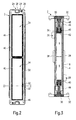
- Fig. 1 is a side perspective view of the essential parts of an embodiment of a heat generating element is shown in exploded view.
- the heat-generating element has a molded plastic injection frame 2, whose central longitudinal axis forms a plane of symmetry of the heat-generating element. This is formed essentially mirror-symmetrical and has on each side of the positioning frame 2 initially provided contact plates 4, which receive between them in the position frame 2 recorded PTC elements 6.
- On the outside of the contact sheets 4 is a two-layer insulating layer 8, comprising an outer insulating film 10 and an inner, directly adjacent to the contact plate 4 ceramic plate 12.
- the ceramic plate 12 is a relatively thin alumina plate, which has a very good dielectric strength of about 28 kV / mm and a good thermal conductivity of more than 24 W / (m K) provides.
- the plastic film 10 is presently formed by a polyamide film having a good thermal conductivity of about 0.45 W / (m K) and a dielectric strength of 4 kV / mm.
- plastic film 10 and the ceramic plate 12 Between the plastic film 10 and the ceramic plate 12 is a few microns thick wax layer whose melting point is tuned with respect to the operating temperature of the heat-generating element, in such a way that the wax melts at operating temperature and between the plastic film and the ceramic plate 12, the abut each other under compressive stress, so distributed that a compensating film is created, which promotes good heat transfer between the two parts 10, 12 of the insulating layer 8.
- the combination of plastic film 10 and ceramic plate 12 leads to an insulating part 8, which has good electrical properties and thermal conduction properties and in particular against breakdown voltages of up to 2000 V, but which also shows the necessary strength at the same time.
- the external insulating foil By the external insulating foil any voltage spikes, which can be generated in particular when applied by pressure against the heat-generating element heat-emitting elements, degraded and homogenized.
- the arranged between the two parts 10, 12 of the insulating wax, optionally also an additional there provided and both parts 10, 12 interconnecting adhesive favors this degradation of voltage spikes. Accordingly, even at higher compressive stresses, which hold a layer structure of heat-generating and heat-emitting elements under bias, there is no risk that the relatively brittle ceramic layer breaks.
- the insulating layer 8 is preferably glued to the outside of the contact plate 4. This is located approximately in the middle of the insulating layer 8 and is formed with a smaller width than the insulating layer 8. However, the respective contact plate 4 projects beyond the insulating layer 8 at the end faces.
- the contact plate 4 is at this the insulating layer 8 superior ends initially significantly reduced in width.
- the contact plate 4 a by free cutting with respect to the width of the contact plate 4 tapered mounting web 14, in which a recess 16 is recessed.
- a corresponding tapered fastening web 18 is also provided with a recess 16. From the lateral edge of this fastening web 18, a web 20 bent out of the plane of the contact sheet 4 goes off, forming the base of a plug connection 22 projecting from the front side of the positioning frame 2.
- the web 20 is engaged in a recess 24 recessed on the positioning frame 2, which opens towards the end face of the positioning frame 2.
- the positioning frame 2 also has at its front end portions on pins 26 which extend in the vertical direction of the heat generating element, ie, at right angles depart from the surface of the position frame 2. During assembly, these pins 26 are inserted into the recesses 16. Thereafter, the pin 26 is melted to form a melt thickening and secured the contact plate 4 in this manner with respect to the positioning frame 2.
- the positioning frame 2 has, in addition to the pins 26, further positioning aids for the positionally accurate arrangement of the contact plate 4 on the positioning frame 2.
- the positioning frame 2 forms on the one hand at the front ends of the contact plate 4 end fixing webs 28, which extend slightly over the top of the contact plate 4 and whose distance from one another corresponds approximately to the length of the contact plate 4.
- the contact plate 4 is positioned in the longitudinal direction.
- boundary edges 30 which also extend beyond the top of the contact plate 4 and whose distance from each other is a little larger than the width of the contact plate 4.
- This bounding edge 30 is surmounted on both sides by limiting webs 32 with inner locking projections, by means of which a heat-emitting element to be arranged on the heat-generating element can be fixed for assembly purposes.
- the heat-generating element are - as is apparent from Fig. 3 - opposite surfaces of the PTC elements 6 on the inner surfaces of the contact plates 4 and are fixed in a frame opening 34 of the positioning frame 2.
- the packing of the PTC elements is spaced from the material of the positioning frame 2 by an insulating gap 36.
- This insulating gap 36 also extends in a direction parallel to the bearing plane between the inside of the contact plate 4 and a tapered inner edge 38 of the position frame surrounding the frame opening 34 circumferentially. Through the insulating gap 38 thereafter, the current-carrying parts of the heat-generating element, d.
- insulating spacer means 40 which surrounds the front end of the inner edge 38 circumferentially.
- the insulating spacer means 40 is formed in the embodiment shown by a silicone strip which receives the front portion of the inner edge 38 in and surrounding it circumferentially.
- the spacing means should only prevent the live parts coming into direct contact with the plastic material of the positioning frame 2.
- the insulating properties of the spacer means 40 are chosen so that this has a better insulation effect than the plastic material of the positioning frame 2 anyway.
- the width of the spacing means 40 in the width direction is selected such that it in any case reaches as far as the wide-side end of the contact sheet 4.
- the spacer means 40 covers the upwardly and downwardly exposed sides of the inner edge 30 and a rim 42 formed circumferentially around the frame opening 34 formed by the inner edge 38.
- the spacer means 40 may thereafter also be referred to as the inner frame opening 34 circumferentially surrounding edge um modeender insulating jacket are considered, which prevents both a direct contact between the PTC element 6 and the thermoplastic material of the positioning frame 2 as well as a direct contact of the contact plates 4 on the positioning frame 2 and to be observed for electrical insulation minimum distance between the ensured parts.
- the embodiment shown in FIGS. 1 to 4 also provides a complete encapsulation of these parts.
- the insulating layer has an edge section 4 which extends on both sides over the contact plate 4 in the transverse direction (FIG. 3). Between this edge portion 4 and the inner edge 38 of the position frame 2 is a sealing bead 46, which is sealingly applied both against the position frame 2 and against the insulating layer 8.
- the encapsulation In the circumferential direction, d. H.
- the encapsulation then has the insulating layers 8 located opposite one another and the arrangement of two sealing elements 46 extending substantially at right angles thereto with the material of the positioning frame 2 provided therebetween. The encapsulation is chosen so that no moisture or contamination from the outside can reach the live parts.
- the sealing bead 46 is formed by a plastic adhesive, which fixes the insulating layer 8 with respect to the position frame 2 and thus includes all provided within the insulating layers 8 parts of the heat-generating element.
- a plastic adhesive which fixes the insulating layer 8 with respect to the position frame 2 and thus includes all provided within the insulating layers 8 parts of the heat-generating element.
- this embodiment can be dispensed with a fixation of the PTC elements 6 with the contact plates 4 with respect to the insulating layer 8 with respect to a positional positioning during operation of the heat-generating element. Nevertheless, such a fixation for manufacturing reasons may be useful.
- Elastomers for example silicone or polyurethane, have proven to be suitable for forming the sealing bead 46 in the form of an adhesive.
- the sealing bead 46 extends in the longitudinal direction of the positioning frame and is provided between the outer edge of the frame opening 34 and the boundary edge 30.
- the sealing element bears against the inner edge 38, which is reduced in thickness.
- a Dichtstoffbegrenzungsrand 48 is provided, which is formed by the positioning frame 2.
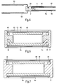
- Figures 5 and 6 show an alternative embodiment of a heat generating element according to the invention with a positioning frame 2, on which the present lower contact plate 4u is arranged by encapsulation.
- the contact plate 4u can have recesses or openings at its edge, through which the highly insulating plastic mass forming the position frame can flow during injection molding and thus can connect the contact plate 4 to the position frame 2.
- the lower contact plate 4u is at its ends to the center of the position frame out, so that the contact plate 4u is securely surrounded by the frame 2 forming the material.
- the positioning frame 2 is made of an electrically high-quality, temperature-resistant (200 ° C) silicone. The embodiment then has a CTI value that ensures safe operation at voltages of about 500V.
- the position frame is manufactured while maintaining the basic structure already described with reference to the previous embodiments, wherein between the material of the positioning frame 2 and the insulating layer 8, a sealing adhesive edge 46 is provided, which in the present case of a Elastomer adhesive is formed. With the interposition of this adhesive strip 46, the mutual insulating layers 8 abut against the positioning frame 2. In this case, the voltage applied to the lower insulating layer 8u strip 46 in particular serves the adhesive connection. Its sealing properties are not so important.
- the insulating layer 8 can also be glued alternatively or in addition flat on the outside of the contact plate 4u.
- both the electrical conductor 4u and the adjoining insulating layer 8u in an injection molding are inserted and overmoulded by the highly insulating plastic compound of the positioning frame 2 (FIG. 7).
- the PTC elements 6 are inserted into the frame openings 34.
- an electrical conductor 4 is now applied to the PTC element (s) 6.
- the immediately applied to this electrical conductor 4 insulating layer 8 is connected to the position frame 2.
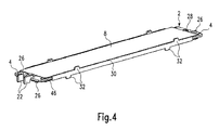
- FIGS 8 and 9 show a fourth embodiment of a heat generating element according to the invention. Identical components are identified with the same reference numerals with respect to the preceding embodiments.
- the PTC elements 6 are accommodated in two frame openings 34 of an elongated position frame 2.
- the PTC elements 6 can bear directly on the edge of the frame 2 surrounding the frame openings 34.
- the opposite upper sides of the sealing beads 46 are approximately at the level of the top of the PTC elements.
- the two sealing beads 46 together with the thickness of the positioning frame 2 at this lateral edge thereof have a height which corresponds approximately to the height of the PTC elements.
- the positioning frame 2 is provided on both sides with superior positioning frame heads 100, which form positioning aids for positionally accurate arrangement of the contact sheets 4.
- Each of the contact plates 4 has its front ends cut out tongues, wherein the left tongue forms the male connector terminal 50 and on the right side only a positioning tongue 102 is provided, which is on all sides insulating received by the right position frame 100 in a recessed therein positioning opening 104, so that the contact plate 4 is held in position secured in position in the longitudinal and transverse direction relative to the position frame 2.
- the position frame head 100 further has a through hole 105 for the male terminal 50.
- the position frame heads 100 also form securing means in the form of latching arms 106, which surround the insulating layer 8 on the outside, on its end face.
- the latching arms 106 are articulated via a common torsion joint 108 on the immovable part of the position frame head 100.
- the locking arms 106 can be pivoted about this Torsionsgelenk 108 so that the opposing locking arms 106 between them free a space that can accommodate just trained as a flat ceramic plate insulating layer 108. After relief of the torsion joint 108 swing the locking arms back and overlap the insulating layer 106. In this case, the insulating layer 8 is biased toward the position frame 2 with the interposition of the sealing bead 46.
- FIG. 8 and 9 may be formed on one side with corresponding detent against the position frame 2 battered insulating 8, whereas on the other side, the insulating layer and / or the contact plate 4 may be secured in a manner to the positioning frame 2, as has already been described above with reference to Figures 6 and 7.
- Fig. 10 another modified embodiment is shown. Also in this embodiment, the same components with respect to the previously discussed embodiments are provided with the same reference numerals.
- the sealing beads 46 are formed integrally on opposite side surfaces of the positioning frame 2 on the positioning frame 2 formed as an injection molding component.
- the position frame 2 is injection molded from silicone.
- the PTC elements 6 are inserted in this frame 2.
- the insulating layers 8 are placed on both sides of the sealing bead 46. The recorded within the position frame 2 components, contact plate 4th and PTC elements 6 are clamped between the insulating layers 8.
- clamping elements 62 which may be formed for example by C-shaped plastic clips, both bias the insulating layers 8 against each other with the interposition of the position frame 2 and the relatively soft and labile position frame 2 serve as a lateral boundary, so that the positioning frame 2 can not bulge outward substantially in the bearing plane of the PTC elements 6. Accordingly, the clamping elements 62 are arranged distributed at predetermined intervals over the entire longitudinal extension of the positioning frame 2 in any case.
- the cooperating with the insulating layer 8 locking projections of the clip elements 62 may be associated with locking recesses or detents which are mounted on the side of the insulating layer. Also, the locking projections may be connected by gluing with the insulating layer 8.
- Conceivable is any configuration that prevents the practical use of the heat generating element on the one hand slipping of the clip elements 62 of the surface of the insulating layer 8 and on the other hand, a possible flat contact the heat-emitting elements on the outside of the insulating layer 8 is not hindered.
- FIG. 11 an embodiment of a heating device according to the invention is shown.
- This comprises a holding device in the form of a circumferentially closed frame 52, which is formed by two frame shells 54.
- a plurality of mutually parallel layers of identically formed heat-generating elements 60 are added.
- the frame 52 includes a spring, not shown, by which the layer structure is held under pretension in the frame 52.
- all the heat-emitting elements 56 are disposed immediately adjacent to a heat-generating element 60.
- the heat-emitting elements 56 shown in FIG. 11 are formed by meandering bent aluminum sheet metal strips.
- the heat-generating elements 60 are located between these individual heat-emitting elements 56 and behind the longitudinal struts 58 of the Lucasein- or outlet opening of the frame 52 passing through the grid.
- One of these longitudinal struts 58 is removed in the middle of the frame 52 for the sake of illustration, so that there is a heat generating element 60 can be seen.
- the force of the spring received in the frame 52 may be such that not only the heat-generating elements 60 and the heat-emitting elements 56 are braced against each other, but also the corresponding sealing beads 46 sealingly biased against the insulating layer 8 and the positioning frame 2, respectively be pressed.
- the sealing effect can be generated solely by spring force.
- the individual heat-generating elements can be provided under bias clamping clip elements or other securing means. It is also possible to adhesively adhere the sealing bead to the insulating layer and / or the position frame. In this case, in any case due to the bias of the spring received in the frame of the sealing bead is compressed and the contact plate 4 flush against the top of the PTC element 6 is applied in order to achieve good contact there. It goes without saying that on the position frame recessed lead-through or positioning opening 104, 105 are dimensioned in this case so that they allow a certain mobility of the contact plate 4 for compression of the sealing bead 46.
- the heat-emitting elements i. H. the radiator elements, potential-free, since this rests with the interposition of the insulating layer 8 against the current-carrying parts.
- the frame 52 is preferably made of plastic, whereby the electrical insulation can be further improved.
- An additional protection especially against unauthorized contact with the live parts of the heater is additionally provided by the grid, which is also formed of plastic and formed integrally with the frame shells 54.
- a plug connection depart from the power supply and / or control lines through which the heater can be connected in terms of control and Strom machinesshunt in a vehicle.
- a housing is indicated, which in addition to the plug connection may also have control or regulating elements.
- a contact surface for the sealing bead 46 superior, formed on the positioning frame 2 mounting edge 30 is missing, also in this embodiment, to be recognized in the side view side surface of the heat generating element substantially through the side wall of the Position frame formed.
- the contact surface for the sealing bead 46 on the side of the positioning frame 2 is surmounted only by the relatively thin sealing bead 46 and the thin ceramic plate 8. It should be noted that the embodiment shown in Figures 8 and 9 has a completely smooth and continuous in the width direction of the heat-generating element surface. The attachment of the ceramic plate 8 to the position frame 2 is carried out only on the provided on the front side locking arms 106.
Landscapes
- Engineering & Computer Science (AREA)
- Physics & Mathematics (AREA)
- Thermal Sciences (AREA)
- Chemical & Material Sciences (AREA)
- Combustion & Propulsion (AREA)
- Mechanical Engineering (AREA)
- General Engineering & Computer Science (AREA)
- Resistance Heating (AREA)
- Air-Conditioning For Vehicles (AREA)
- Direct Air Heating By Heater Or Combustion Gas (AREA)
- Thermistors And Varistors (AREA)
- Surface Heating Bodies (AREA)
Priority Applications (6)
| Application Number | Priority Date | Filing Date | Title |
|---|---|---|---|
| ES06017063T ES2303712T3 (es) | 2005-09-23 | 2006-08-16 | Elemento generador de calor para un dispositivo de calefaccion. |
| EP06017063A EP1768459B1 (fr) | 2005-09-23 | 2006-08-16 | Elément chauffant d'un dispositif de chauffage |
| DE502006000793T DE502006000793D1 (de) | 2005-09-23 | 2006-08-16 | Wärmeerzeugendes Element einer Heizvorrichtung |
| US11/534,470 US7777161B2 (en) | 2005-09-23 | 2006-09-22 | Heat-generating element of a heating device |
| JP2006257828A JP4170355B2 (ja) | 2005-09-23 | 2006-09-22 | 加熱装置の熱発生要素 |
| KR1020060093006A KR100850476B1 (ko) | 2005-09-23 | 2006-09-25 | 난방 장치의 열 생성 부재 |
Applications Claiming Priority (3)
| Application Number | Priority Date | Filing Date | Title |
|---|---|---|---|
| EP05020753A EP1768458B1 (fr) | 2005-09-23 | 2005-09-23 | Elément chauffant d'un dispositif de chauffage |
| EP05020752A EP1768457B1 (fr) | 2005-09-23 | 2005-09-23 | Element chauffant d'un dispositif de chauffage |
| EP06017063A EP1768459B1 (fr) | 2005-09-23 | 2006-08-16 | Elément chauffant d'un dispositif de chauffage |
Publications (2)
| Publication Number | Publication Date |
|---|---|
| EP1768459A1 true EP1768459A1 (fr) | 2007-03-28 |
| EP1768459B1 EP1768459B1 (fr) | 2008-05-21 |
Family
ID=37546733
Family Applications (1)
| Application Number | Title | Priority Date | Filing Date |
|---|---|---|---|
| EP06017063A Active EP1768459B1 (fr) | 2005-09-23 | 2006-08-16 | Elément chauffant d'un dispositif de chauffage |
Country Status (6)
| Country | Link |
|---|---|
| US (1) | US7777161B2 (fr) |
| EP (1) | EP1768459B1 (fr) |
| JP (1) | JP4170355B2 (fr) |
| KR (1) | KR100850476B1 (fr) |
| DE (1) | DE502006000793D1 (fr) |
| ES (1) | ES2303712T3 (fr) |
Cited By (12)
| Publication number | Priority date | Publication date | Assignee | Title |
|---|---|---|---|---|
| EP2017103A1 (fr) * | 2007-07-18 | 2009-01-21 | Catem GmbH & Co. KG | Dispositif de chauffage électrique |
| EP2393336A1 (fr) | 2010-06-04 | 2011-12-07 | Behr France Rouffach S.A.R.L. | Caloporteur |
| EP2466222A1 (fr) | 2010-12-20 | 2012-06-20 | Eberspächer catem GmbH & Co. KG | Dispositif de chauffage électrique |
| EP2731400A1 (fr) * | 2012-11-12 | 2014-05-14 | Betacera Inc. | Appareil de chauffage électrique avec mécanisme imperméable à l'eau |
| EP3101999A1 (fr) | 2015-06-02 | 2016-12-07 | Eberspächer catem GmbH & Co. KG | Élement de chauffage a coefficient de temperature positif (ctp) et dispositif de chauffage electrique pour un vehicule automobile comprenant un tel element de chauffage ctp |
| EP3101364A1 (fr) * | 2015-06-02 | 2016-12-07 | Eberspächer catem GmbH & Co. KG | Dispositif de chauffage électrique |
| EP3101998A1 (fr) | 2015-06-02 | 2016-12-07 | Eberspächer catem GmbH & Co. KG | Élément de chauffage ptc et dispositif de chauffage électrique comprenant un tel élément de chauffage ptc et procédé de fabrication d'un dispositif de chauffage électrique |
| DE102016224296A1 (de) | 2016-12-06 | 2018-06-07 | Eberspächer Catem Gmbh & Co. Kg | Elektrische heizvorrichtung |
| EP3503671A1 (fr) | 2017-12-22 | 2019-06-26 | Eberspächer catem GmbH & Co. KG | Dispositif de chauffage électrique ainsi que son procédé de fabrication |
| DE102017223785A1 (de) | 2017-12-22 | 2019-06-27 | Eberspächer Catem Gmbh & Co. Kg | Verfahren zur Herstellung eines wärmeerzeugenden Elementes |
| CN110430627A (zh) * | 2019-07-29 | 2019-11-08 | 江苏沙子电器有限公司 | 一种耐高压型ptc加热器及生产工艺 |
| FR3135183A1 (fr) * | 2022-04-29 | 2023-11-03 | Valeo Systemes Thermiques | Corps de chauffe pour radiateur électrique |
Families Citing this family (27)
| Publication number | Priority date | Publication date | Assignee | Title |
|---|---|---|---|---|
| DE102005030392A1 (de) * | 2005-06-29 | 2007-01-04 | BSH Bosch und Siemens Hausgeräte GmbH | Hausgerät sowie Garguträger-Haltevorrichtung für ein Hausgerät |
| JP4981386B2 (ja) * | 2006-08-30 | 2012-07-18 | 三菱重工業株式会社 | 熱媒体加熱装置およびそれを用いた車両用空調装置 |
| DE502006003627D1 (de) | 2006-10-25 | 2009-06-10 | Catem Gmbh & Co Kg | Wärmeerzeugendes Element für eine elektrische Heizvorrichtung und Verfahren zur Herstellung derselben |
| EP2017546B1 (fr) * | 2007-07-18 | 2016-04-13 | Eberspächer catem GmbH & Co. KG | Procédé de fabrication d'un dispositif de chauffage électrique tout comme dispositif de chauffage électrique |
| ES2345574T3 (es) * | 2008-04-11 | 2010-09-27 | EBERSPACHER CATEM GMBH & CO. KG | Elemento generador de calor y dispositivo calefactor que comprende un elemento generador de calor. |
| EP2190258A1 (fr) | 2008-11-20 | 2010-05-26 | Behr France Rouffach SAS | Caloporteur |
| KR101076191B1 (ko) * | 2008-12-05 | 2011-10-21 | 현대자동차주식회사 | 피티씨 로드 조립체 및 이를 이용한 피티씨 히터 |
| KR101114583B1 (ko) * | 2008-12-05 | 2012-03-05 | 현대자동차주식회사 | 피티씨 로드 조립체 |
| JP5535740B2 (ja) * | 2010-04-14 | 2014-07-02 | 三菱重工業株式会社 | 熱媒体加熱装置およびそれを用いた車両用空調装置 |
| US8698051B2 (en) * | 2011-07-14 | 2014-04-15 | Amphenol Thermometrics, Inc. | Heating system, heater, and methods of heating a component |
| EP2607121B2 (fr) * | 2011-12-22 | 2020-07-08 | Eberspächer catem GmbH & Co. KG | Dispositif de chauffage électrique, en particulier pour un véhicule automobile |
| EP2607808B1 (fr) * | 2011-12-22 | 2017-09-27 | Eberspächer catem GmbH & Co. KG | Elément générateur de chaleur |
| EP2608631B1 (fr) * | 2011-12-22 | 2016-09-14 | Eberspächer catem GmbH & Co. KG | Elément générateur de chaleur |
| EP2608633B1 (fr) * | 2011-12-22 | 2020-08-26 | Eberspächer catem GmbH & Co. KG | Elément générateur de chaleur |
| US9839072B2 (en) | 2012-03-08 | 2017-12-05 | Eberspacher Catem Gmbh & Co. Kg | Heat generating element with connection structure |
| DE102012109801B4 (de) * | 2012-10-15 | 2015-02-05 | Borgwarner Ludwigsburg Gmbh | Elektrische Heizvorrichtung |
| US20140124500A1 (en) * | 2012-11-05 | 2014-05-08 | Betacera Inc. | Insulated heater |
| US20140124499A1 (en) * | 2012-11-05 | 2014-05-08 | Betacera Inc. | Electric heating apparatus with waterproof mechanism |
| JP6169781B2 (ja) * | 2013-04-28 | 2017-07-26 | ビーワイディー カンパニー リミテッドByd Company Limited | 電気ヒータ、デフロスタ、暖房空調システム及び車輌 |
| EP2969673B1 (fr) * | 2013-04-28 | 2020-03-18 | BYD Company Limited | Dégivreur et véhicule le possédant |
| KR101879984B1 (ko) * | 2017-03-27 | 2018-07-18 | 버슘머트리얼즈 유에스, 엘엘씨 | 히팅 자켓 |
| DE102017206964A1 (de) * | 2017-04-25 | 2018-10-25 | Mahle International Gmbh | Elektrische Heizeinrichtung |
| US10774802B2 (en) | 2017-05-15 | 2020-09-15 | Phillips & Temro Industries Inc. | Intake air heating system for a vehicle |
| DE102018205316A1 (de) * | 2018-04-09 | 2019-10-10 | Mahle International Gmbh | Elektrische Heizeinrichtung |
| WO2021166293A1 (fr) | 2020-02-21 | 2021-08-26 | 日本碍子株式会社 | Élément chauffant permettant de chauffer un intérieur de véhicule et appareil de chauffage permettant de chauffer un intérieur de véhicule |
| DE102020203390A1 (de) | 2020-03-17 | 2021-09-23 | Eberspächer catem Hermsdorf GmbH & Co. KG | Elektrische heizeinrichtung und verfahren zu deren herstellung |
| KR102511894B1 (ko) * | 2021-01-07 | 2023-03-21 | 우리산업 주식회사 | 차량 히터용 히트 로드 조립체 및 제조방법 |
Citations (3)
| Publication number | Priority date | Publication date | Assignee | Title |
|---|---|---|---|---|
| DE2845894A1 (de) * | 1978-10-21 | 1980-04-30 | Eichenauer Fa Fritz | Elektrische widerstandsheizeinrichtung |
| DE3022034A1 (de) * | 1980-06-12 | 1981-12-17 | Reinhold Ing.(grad.) 6990 Bad Mergentheim Barlian | Beheizungsvorrichtung mit kaltleiter-heizelementen |
| EP1432287A1 (fr) * | 2002-12-19 | 2004-06-23 | Catem GmbH & Co.KG | Dispositif de chauffage électrique avec boítier |
Family Cites Families (19)
| Publication number | Priority date | Publication date | Assignee | Title |
|---|---|---|---|---|
| DE2845965C2 (de) * | 1978-10-21 | 1983-01-20 | Fritz Eichenauer GmbH & Co KG, 6744 Kandel | Elektrisches Widerstandsheizelement |
| DE3065380D1 (en) | 1979-09-28 | 1983-11-24 | Siemens Ag | Heating arrangement using a p.t.c. resistance heating element |
| DE3208802A1 (de) | 1980-12-13 | 1983-09-22 | C.S. Fudickar Kg, 5600 Wuppertal | Elektrische heizvorrichtung fuer beheizte apparate |
| JPH0436071A (ja) | 1990-05-31 | 1992-02-06 | Fuji Electric Co Ltd | S形チューブラ水車 |
| US5198640A (en) | 1991-05-28 | 1993-03-30 | Yang Chiung Hsiang | Fully clad electric ptc heater with a finned protective casing |
| US5326418A (en) * | 1992-04-14 | 1994-07-05 | Yeh Yuan Chang | Method of making positive-temperature-coefficient thermistor heating element |
| JPH0673654A (ja) | 1992-08-27 | 1994-03-15 | Unitika Ltd | ポリアミド系極細繊維不織布及びその製造方法 |
| US5471034A (en) * | 1993-03-17 | 1995-11-28 | Texas Instruments Incorporated | Heater apparatus and process for heating a fluid stream with PTC heating elements electrically connected in series |
| DE69424478T2 (de) * | 1993-07-20 | 2001-01-18 | Tdk Corp | Keramisches Heizelement |
| JPH07153554A (ja) * | 1993-11-30 | 1995-06-16 | Nippon Tungsten Co Ltd | 発熱装置 |
| DE4434613A1 (de) * | 1994-09-28 | 1996-04-04 | Behr Gmbh & Co | Elektrische Heizeinrichtung, insbesondere für ein Kraftfahrzeug |
| US6178292B1 (en) * | 1997-02-06 | 2001-01-23 | Denso Corporation | Core unit of heat exchanger having electric heater |
| JP3794116B2 (ja) * | 1997-08-06 | 2006-07-05 | 株式会社デンソー | 暖房用熱交換器 |
| US6965732B2 (en) * | 2000-08-22 | 2005-11-15 | A.T.C.T. Advanced Thermal Chips Technologies Ltd. | Liquid heating method and apparatus particularly useful for vaporizing a liquid condensate from cooling devices |
| ATE458378T1 (de) * | 2001-12-06 | 2010-03-15 | Eberspaecher Catem Gmbh & Co K | Elektrische heizvorrichtung |
| DE10213923A1 (de) | 2002-03-28 | 2003-10-09 | Votup & Co Innovative Keramik | Elektrisches Heizelement |
| EP1515588B1 (fr) | 2003-09-10 | 2015-08-12 | Denso Corporation | Corps de chauffe électrique à haute performance et de fabrication efficace |
| EP1515587B1 (fr) * | 2003-09-11 | 2006-12-13 | Catem GmbH & Co. KG | Dispositif de chauffage électrique muni d'un élément chauffant scellé |
| KR100545833B1 (ko) * | 2003-12-11 | 2006-01-31 | 한진전자공업주식회사 | 전열기용 전기발열체의 조립 구조 |
-
2006
- 2006-08-16 ES ES06017063T patent/ES2303712T3/es active Active
- 2006-08-16 EP EP06017063A patent/EP1768459B1/fr active Active
- 2006-08-16 DE DE502006000793T patent/DE502006000793D1/de active Active
- 2006-09-22 US US11/534,470 patent/US7777161B2/en not_active Expired - Fee Related
- 2006-09-22 JP JP2006257828A patent/JP4170355B2/ja not_active Expired - Fee Related
- 2006-09-25 KR KR1020060093006A patent/KR100850476B1/ko not_active IP Right Cessation
Patent Citations (3)
| Publication number | Priority date | Publication date | Assignee | Title |
|---|---|---|---|---|
| DE2845894A1 (de) * | 1978-10-21 | 1980-04-30 | Eichenauer Fa Fritz | Elektrische widerstandsheizeinrichtung |
| DE3022034A1 (de) * | 1980-06-12 | 1981-12-17 | Reinhold Ing.(grad.) 6990 Bad Mergentheim Barlian | Beheizungsvorrichtung mit kaltleiter-heizelementen |
| EP1432287A1 (fr) * | 2002-12-19 | 2004-06-23 | Catem GmbH & Co.KG | Dispositif de chauffage électrique avec boítier |
Cited By (19)
| Publication number | Priority date | Publication date | Assignee | Title |
|---|---|---|---|---|
| EP2017103A1 (fr) * | 2007-07-18 | 2009-01-21 | Catem GmbH & Co. KG | Dispositif de chauffage électrique |
| EP2025541A1 (fr) * | 2007-07-18 | 2009-02-18 | Catem GmbH & Co. KG | Elément d'un dispositif de chauffage produisant de la chaleur électrique |
| US8362406B2 (en) | 2007-07-18 | 2013-01-29 | Catem Gmbh & Co. Kg | Method of manufacturing an electric heating device and electric heating devices |
| EP2393336A1 (fr) | 2010-06-04 | 2011-12-07 | Behr France Rouffach S.A.R.L. | Caloporteur |
| EP2466222A1 (fr) | 2010-12-20 | 2012-06-20 | Eberspächer catem GmbH & Co. KG | Dispositif de chauffage électrique |
| EP2731400A1 (fr) * | 2012-11-12 | 2014-05-14 | Betacera Inc. | Appareil de chauffage électrique avec mécanisme imperméable à l'eau |
| EP3101998A1 (fr) | 2015-06-02 | 2016-12-07 | Eberspächer catem GmbH & Co. KG | Élément de chauffage ptc et dispositif de chauffage électrique comprenant un tel élément de chauffage ptc et procédé de fabrication d'un dispositif de chauffage électrique |
| EP3101364A1 (fr) * | 2015-06-02 | 2016-12-07 | Eberspächer catem GmbH & Co. KG | Dispositif de chauffage électrique |
| EP3101999A1 (fr) | 2015-06-02 | 2016-12-07 | Eberspächer catem GmbH & Co. KG | Élement de chauffage a coefficient de temperature positif (ctp) et dispositif de chauffage electrique pour un vehicule automobile comprenant un tel element de chauffage ctp |
| DE102016224296A1 (de) | 2016-12-06 | 2018-06-07 | Eberspächer Catem Gmbh & Co. Kg | Elektrische heizvorrichtung |
| EP3334243A1 (fr) | 2016-12-06 | 2018-06-13 | Eberspächer catem GmbH & Co. KG | Dispositif de chauffage électrique |
| EP3334242A1 (fr) | 2016-12-06 | 2018-06-13 | Eberspächer catem GmbH & Co. KG | Dispositif de chauffage électrique |
| EP3592105A1 (fr) | 2016-12-06 | 2020-01-08 | Eberspächer catem GmbH & Co. KG | Dispositif de chauffage électrique |
| EP3503671A1 (fr) | 2017-12-22 | 2019-06-26 | Eberspächer catem GmbH & Co. KG | Dispositif de chauffage électrique ainsi que son procédé de fabrication |
| DE102017223779A1 (de) | 2017-12-22 | 2019-06-27 | Eberspächer Catem Gmbh & Co. Kg | Elektrische Heizvorrichtung sowie ein Verfahren zur Herstellung derselben |
| DE102017223785A1 (de) | 2017-12-22 | 2019-06-27 | Eberspächer Catem Gmbh & Co. Kg | Verfahren zur Herstellung eines wärmeerzeugenden Elementes |
| CN110430627A (zh) * | 2019-07-29 | 2019-11-08 | 江苏沙子电器有限公司 | 一种耐高压型ptc加热器及生产工艺 |
| CN110430627B (zh) * | 2019-07-29 | 2022-02-25 | 江苏沙子电器有限公司 | 一种耐高压型ptc加热器及生产工艺 |
| FR3135183A1 (fr) * | 2022-04-29 | 2023-11-03 | Valeo Systemes Thermiques | Corps de chauffe pour radiateur électrique |
Also Published As
| Publication number | Publication date |
|---|---|
| ES2303712T3 (es) | 2008-08-16 |
| KR20070034445A (ko) | 2007-03-28 |
| EP1768459B1 (fr) | 2008-05-21 |
| US20070068927A1 (en) | 2007-03-29 |
| DE502006000793D1 (de) | 2008-07-03 |
| JP2007147259A (ja) | 2007-06-14 |
| KR100850476B1 (ko) | 2008-08-07 |
| US7777161B2 (en) | 2010-08-17 |
| JP4170355B2 (ja) | 2008-10-22 |
Similar Documents
| Publication | Publication Date | Title |
|---|---|---|
| EP1768459B1 (fr) | Elément chauffant d'un dispositif de chauffage | |
| EP1768457B1 (fr) | Element chauffant d'un dispositif de chauffage | |
| EP1916874B1 (fr) | Elément d'un dispositif de chauffage produisant de la chaleur | |
| EP2337425B1 (fr) | Dispositif de chauffage électrique et élément produisant de la chaleur d'un dispositif de chauffage électrique | |
| EP2607121B2 (fr) | Dispositif de chauffage électrique, en particulier pour un véhicule automobile | |
| EP1916873B1 (fr) | Elément générateur de la chaleur pour un dispositif chauffant électrique et son procédé de fabrication | |
| EP1921896B1 (fr) | Elément produisant de la chaleur pour dispositif chauffant électrique et son procédé de fabrication | |
| EP3493650B1 (fr) | Dispositif de chauffage électrique | |
| EP3416456B1 (fr) | Dispositif de chauffage électrique et élément de chauffage ptc pour un tel dispositif de chauffage électrique | |
| EP3079442B1 (fr) | Dispositif de chauffage électrique et cadre associé | |
| EP3101998B1 (fr) | Élément de chauffage ptc et dispositif de chauffage électrique comprenant un tel élément de chauffage ptc et procédé de fabrication d'un dispositif de chauffage électrique | |
| EP2109345B1 (fr) | Elément produisant de la chaleur et dispositif de chauffage comprenant un élément produisant de la chaleur | |
| EP2440005B1 (fr) | Dispositif de chauffage électrique et son procédé de fabrication | |
| EP2873296B1 (fr) | Élément chauffant | |
| EP2025541B1 (fr) | Elément d'un dispositif de chauffage produisant de la chaleur électrique | |
| EP2607808B1 (fr) | Elément générateur de chaleur | |
| DE4434613A1 (de) | Elektrische Heizeinrichtung, insbesondere für ein Kraftfahrzeug | |
| EP2608631A1 (fr) | Elément générateur de chaleur | |
| DE102012025445A1 (de) | Elektrische Heizvorrichtung | |
| EP2957840B1 (fr) | Dispositif de chauffage électrique | |
| DE102018220333A1 (de) | Elektrische Heizvorrichtung | |
| EP4337897A1 (fr) | Dispositif de chauffage et procédé de fabrication d'un dispositif de chauffage | |
| EP4084577A2 (fr) | Dispositif de chauffage électrique et son procédé de fabrication |
Legal Events
| Date | Code | Title | Description |
|---|---|---|---|
| PUAI | Public reference made under article 153(3) epc to a published international application that has entered the european phase |
Free format text: ORIGINAL CODE: 0009012 |
|
| AK | Designated contracting states |
Kind code of ref document: A1 Designated state(s): AT BE BG CH CY CZ DE DK EE ES FI FR GB GR HU IE IS IT LI LT LU LV MC NL PL PT RO SE SI SK TR |
|
| AX | Request for extension of the european patent |
Extension state: AL BA HR MK YU |
|
| 17P | Request for examination filed |
Effective date: 20070619 |
|
| 17Q | First examination report despatched |
Effective date: 20071002 |
|
| GRAP | Despatch of communication of intention to grant a patent |
Free format text: ORIGINAL CODE: EPIDOSNIGR1 |
|
| AKX | Designation fees paid |
Designated state(s): DE ES FR GB IT |
|
| GRAS | Grant fee paid |
Free format text: ORIGINAL CODE: EPIDOSNIGR3 |
|
| GRAA | (expected) grant |
Free format text: ORIGINAL CODE: 0009210 |
|
| AK | Designated contracting states |
Kind code of ref document: B1 Designated state(s): DE ES FR GB IT |
|
| REG | Reference to a national code |
Ref country code: GB Ref legal event code: FG4D Free format text: NOT ENGLISH |
|
| REF | Corresponds to: |
Ref document number: 502006000793 Country of ref document: DE Date of ref document: 20080703 Kind code of ref document: P |
|
| REG | Reference to a national code |
Ref country code: ES Ref legal event code: FG2A Ref document number: 2303712 Country of ref document: ES Kind code of ref document: T3 |
|
| PLBE | No opposition filed within time limit |
Free format text: ORIGINAL CODE: 0009261 |
|
| STAA | Information on the status of an ep patent application or granted ep patent |
Free format text: STATUS: NO OPPOSITION FILED WITHIN TIME LIMIT |
|
| 26N | No opposition filed |
Effective date: 20090224 |
|
| PGFP | Annual fee paid to national office [announced via postgrant information from national office to epo] |
Ref country code: GB Payment date: 20110830 Year of fee payment: 6 Ref country code: ES Payment date: 20110808 Year of fee payment: 6 |
|
| GBPC | Gb: european patent ceased through non-payment of renewal fee |
Effective date: 20120816 |
|
| PG25 | Lapsed in a contracting state [announced via postgrant information from national office to epo] |
Ref country code: GB Free format text: LAPSE BECAUSE OF NON-PAYMENT OF DUE FEES Effective date: 20120816 |
|
| REG | Reference to a national code |
Ref country code: ES Ref legal event code: FD2A Effective date: 20131022 |
|
| PG25 | Lapsed in a contracting state [announced via postgrant information from national office to epo] |
Ref country code: ES Free format text: LAPSE BECAUSE OF NON-PAYMENT OF DUE FEES Effective date: 20120817 |
|
| REG | Reference to a national code |
Ref country code: FR Ref legal event code: PLFP Year of fee payment: 11 |
|
| REG | Reference to a national code |
Ref country code: FR Ref legal event code: PLFP Year of fee payment: 12 |
|
| REG | Reference to a national code |
Ref country code: FR Ref legal event code: PLFP Year of fee payment: 13 |
|
| PGFP | Annual fee paid to national office [announced via postgrant information from national office to epo] |
Ref country code: IT Payment date: 20210831 Year of fee payment: 16 Ref country code: FR Payment date: 20210823 Year of fee payment: 16 |
|
| PG25 | Lapsed in a contracting state [announced via postgrant information from national office to epo] |
Ref country code: IT Free format text: LAPSE BECAUSE OF NON-PAYMENT OF DUE FEES Effective date: 20220816 Ref country code: FR Free format text: LAPSE BECAUSE OF NON-PAYMENT OF DUE FEES Effective date: 20220831 |
|
| PGFP | Annual fee paid to national office [announced via postgrant information from national office to epo] |
Ref country code: DE Payment date: 20230822 Year of fee payment: 18 |