EP2466222A1 - Dispositif de chauffage électrique - Google Patents
Dispositif de chauffage électrique Download PDFInfo
- Publication number
- EP2466222A1 EP2466222A1 EP10015844A EP10015844A EP2466222A1 EP 2466222 A1 EP2466222 A1 EP 2466222A1 EP 10015844 A EP10015844 A EP 10015844A EP 10015844 A EP10015844 A EP 10015844A EP 2466222 A1 EP2466222 A1 EP 2466222A1
- Authority
- EP
- European Patent Office
- Prior art keywords
- housing
- heating device
- electric heating
- heating block
- contact protection
- Prior art date
- Legal status (The legal status is an assumption and is not a legal conclusion. Google has not performed a legal analysis and makes no representation as to the accuracy of the status listed.)
- Granted
Links
- 238000005485 electric heating Methods 0.000 title claims description 11
- 238000010438 heat treatment Methods 0.000 claims abstract description 59
- 239000004033 plastic Substances 0.000 claims abstract description 50
- 125000006850 spacer group Chemical group 0.000 claims description 34
- 239000011810 insulating material Substances 0.000 claims description 3
- 238000001746 injection moulding Methods 0.000 claims description 2
- 239000002184 metal Substances 0.000 description 8
- 238000002347 injection Methods 0.000 description 4
- 239000007924 injection Substances 0.000 description 4
- 239000000463 material Substances 0.000 description 4
- 238000005538 encapsulation Methods 0.000 description 2
- 238000009413 insulation Methods 0.000 description 2
- 238000004519 manufacturing process Methods 0.000 description 2
- 238000011144 upstream manufacturing Methods 0.000 description 2
- 239000004677 Nylon Substances 0.000 description 1
- 239000004809 Teflon Substances 0.000 description 1
- 229920006362 Teflon® Polymers 0.000 description 1
- 150000001875 compounds Chemical class 0.000 description 1
- 230000001186 cumulative effect Effects 0.000 description 1
- 230000000694 effects Effects 0.000 description 1
- 238000010292 electrical insulation Methods 0.000 description 1
- 239000012777 electrically insulating material Substances 0.000 description 1
- 238000009434 installation Methods 0.000 description 1
- 238000012423 maintenance Methods 0.000 description 1
- 238000000465 moulding Methods 0.000 description 1
- 229920001778 nylon Polymers 0.000 description 1
- 238000009420 retrofitting Methods 0.000 description 1
- 238000005507 spraying Methods 0.000 description 1
Images


Classifications
-
- F—MECHANICAL ENGINEERING; LIGHTING; HEATING; WEAPONS; BLASTING
- F24—HEATING; RANGES; VENTILATING
- F24H—FLUID HEATERS, e.g. WATER OR AIR HEATERS, HAVING HEAT-GENERATING MEANS, e.g. HEAT PUMPS, IN GENERAL
- F24H3/00—Air heaters
- F24H3/02—Air heaters with forced circulation
- F24H3/04—Air heaters with forced circulation the air being in direct contact with the heating medium, e.g. electric heating element
- F24H3/0405—Air heaters with forced circulation the air being in direct contact with the heating medium, e.g. electric heating element using electric energy supply, e.g. the heating medium being a resistive element; Heating by direct contact, i.e. with resistive elements, electrodes and fins being bonded together without additional element in-between
-
- B—PERFORMING OPERATIONS; TRANSPORTING
- B60—VEHICLES IN GENERAL
- B60H—ARRANGEMENTS OF HEATING, COOLING, VENTILATING OR OTHER AIR-TREATING DEVICES SPECIALLY ADAPTED FOR PASSENGER OR GOODS SPACES OF VEHICLES
- B60H1/00—Heating, cooling or ventilating [HVAC] devices
- B60H1/22—Heating, cooling or ventilating [HVAC] devices the heat being derived otherwise than from the propulsion plant
-
- F—MECHANICAL ENGINEERING; LIGHTING; HEATING; WEAPONS; BLASTING
- F24—HEATING; RANGES; VENTILATING
- F24H—FLUID HEATERS, e.g. WATER OR AIR HEATERS, HAVING HEAT-GENERATING MEANS, e.g. HEAT PUMPS, IN GENERAL
- F24H3/00—Air heaters
- F24H3/02—Air heaters with forced circulation
- F24H3/04—Air heaters with forced circulation the air being in direct contact with the heating medium, e.g. electric heating element
- F24H3/0405—Air heaters with forced circulation the air being in direct contact with the heating medium, e.g. electric heating element using electric energy supply, e.g. the heating medium being a resistive element; Heating by direct contact, i.e. with resistive elements, electrodes and fins being bonded together without additional element in-between
- F24H3/0429—For vehicles
- F24H3/0452—Frame constructions
- F24H3/0464—Two-piece frames, e.g. two-shell frames, also including frames as a central body with two covers
-
- F—MECHANICAL ENGINEERING; LIGHTING; HEATING; WEAPONS; BLASTING
- F24—HEATING; RANGES; VENTILATING
- F24H—FLUID HEATERS, e.g. WATER OR AIR HEATERS, HAVING HEAT-GENERATING MEANS, e.g. HEAT PUMPS, IN GENERAL
- F24H9/00—Details
- F24H9/18—Arrangement or mounting of grates or heating means
- F24H9/1854—Arrangement or mounting of grates or heating means for air heaters
- F24H9/1863—Arrangement or mounting of electric heating means
- F24H9/1872—PTC
-
- H—ELECTRICITY
- H05—ELECTRIC TECHNIQUES NOT OTHERWISE PROVIDED FOR
- H05B—ELECTRIC HEATING; ELECTRIC LIGHT SOURCES NOT OTHERWISE PROVIDED FOR; CIRCUIT ARRANGEMENTS FOR ELECTRIC LIGHT SOURCES, IN GENERAL
- H05B3/00—Ohmic-resistance heating
- H05B3/10—Heating elements characterised by the composition or nature of the materials or by the arrangement of the conductor
- H05B3/12—Heating elements characterised by the composition or nature of the materials or by the arrangement of the conductor characterised by the composition or nature of the conductive material
- H05B3/14—Heating elements characterised by the composition or nature of the materials or by the arrangement of the conductor characterised by the composition or nature of the conductive material the material being non-metallic
Definitions
- the present invention relates to an electric heating device, in particular a heating device as auxiliary heater for a motor vehicle, with a heating block, which is held in a housing housing opposite openings forming housing and parallel layers comprises at least one heat-emitting element and a heat-generating element circumferentially encloses.
- a generic electrical heating device of the aforementioned type usually has a heat-generating element with at least one PTC element, on whose opposite side surfaces bear electrically conductive metal bands, via which the PTC element is energized.
- This current is usually at 12 volts.
- This operating voltage is harmless, so that usually no special measures must be taken to prevent accidental contact of the heating block is prevented.
- the present invention is based on the problem to provide an electric heater of the type mentioned, which can be operated safely even at high operating voltages.
- the above-mentioned electric heater is further developed by at least one contact protection covering an insulating cover of the respective housing opening.
- a housing opening in particular the one in the direction of flow, i. provided by the air flowing through the heater first flowed through the housing opening with a contact protection.
- both of the opposing and the normally planar heating block between them enclosing housing openings are covered by a contact protection.
- the contact protection covers in particular the current-carrying parts of the heating block. The protection against contact is selected so tightly that a user can at least not reach the heating block with his or her fingers through the frame opening.
- the contact protection is designed such that even tools usually used for repair purposes can not pass through the frame opening through to the heating block.
- the idea here is, in particular, a relatively close-meshed plastic net.
- the plastic net should be made of a relatively temperature-resistant plastic, in particular nylon or Teflon.
- the plastic mesh can also be considered as lattice-shaped.
- narrow mesh preferably means that the mesh size is set between 0.7 and 1.0 mm, preferably between 0.8 and 0.9 mm.
- the aim should be to insert a 1.0 mm diameter test wire into the heater block at a force of 1 N, i.e., in the heating block. through the contact protection, to prevent.
- the area open to the flow through the contact protection should be selected to be between approximately 75 and 90%, preferably between 85 and 90%.
- the present invention a secure contact protection is provided, so that it is no longer necessary to provide an insulating layer between the heat-generating elements and the heat-emitting elements.
- the efficiency of the heater according to the invention is therefore compared to that of the EP 1 768 459 A1 Previously improved, especially when a multi-layer redundant insulating layer is formed, which has a relatively poor thermal conductivity.
- the heating block is circumferentially enclosed by the usually made of an insulating material, especially plastic housing, whereas the housing openings released from the housing and opposing housing openings are so far covered by the contact protection, especially by the plastic grid, that to be heated Medium, usually air, can pass through the contact protection through to the heating block, in particular to the lying behind the contact protection current-carrying components of the heating block in the flow direction, but not body parts of a technician or maintenance personnel or tools used by these people or in a channel for air flow reached, if necessary, with the air flow deported foreign body.
- the contact protection especially by the plastic grid
- the plastic net is fastened to a strut arrangement whose struts span the respective housing openings, it is prevented that the plastic net can rest on the surface of the heating block.
- the strut assembly may be formed by one or more, parallel to each other extending struts or a grid arrangement.
- the individual struts or bars of the strut assembly are preferably formed so stiff that under the usual load no sufficient deflection takes place in such a way that the plastic mesh can invest in the surface exposed to the housing opening of the heating block.
- the plastic net is connected to the struts of the strut arrangement by overmolding the plastic net with a plastic component forming the strut arrangement.
- an injection mold which comprises a mold cavity for forming the strut assembly.
- the mold cavity is preferably designed such that the plastic component for forming the strut assembly is formed not only on one side of the plastic net, but also on the opposite side, so that the plastic net is sealed after over-molding of plastic compound solidified on both sides of the plastic net ,
- the strut or grid arrangement is preferably designed so that the struts extending in any case parallel to the layers of the heating block are at the same height as the heat-generating elements, so that the medium to be heated can pass over the heat-emitting elements unhindered.
- at least one spacer element is provided between the heating block and the contact protection.
- the or the spacer elements are chosen so that usually a distance between the contact protection and the heating block of between 4 and 8 mm is set. For conceivable deflections of the contact protection, the distance between the heating block and the contact protection should be at least 2 mm by appropriate dimensioning of the spacer or elements.
- the spacer elements may be provided on both sides of the heating block between this and the frame protection openings covered by the contact protection.
- the spacer element is formed by a strut of the strut arrangement on the inside superior distance support and / or by a spacer web, which projects beyond a PTC element receiving at least one frame of the heat-emitting element and preferably integrally formed on this.
- the heat generating element is formed in a conventional manner by at least one PTC element which is provided between parallel extending metal bands and which is accommodated in a positioning frame made of an insulating material.
- the positioning frame usually has a plurality of receiving openings for receiving one or more PTC elements.
- the position frame has a smaller thickness than the thickness of the PTC elements.
- the positioning frame also forms the spacer element, which projects beyond the substantially planar heating block and keeps the contact protection, especially the plastic net at a distance from the surface of the heating block.
- the positioning frame is usually extended out of the plane of the heating block and projects beyond it.
- the at least one strut of a strut arrangement which passes through the housing opening, is formed as a spacer element.
- the struts can extend parallel to the layers of the heat-emitting elements and these upstream.
- at right angles to these struts extending cross struts may be provided with spacer webs.
- the spacer support can cooperate with the spacer web, which is formed by the positioning frame, to effect the necessary distance between the contact protection and the elements of the heating block.
- the distance supports and the spacer webs may be formed in the longitudinal direction continuously to the struts or position frames.
- At the intersection of the spacer support and the spacer web at least one of the spacer support and the spacer web can have a recess receiving the other, so that a certain linking of the two elements results.
- the strut assembly is clipped together with the plastic mesh to the housing.
- This embodiment offers the possibility to retrofit the contact protection according to the invention in already installed electric heaters.
- the clipping is usually done by locking elements, which are formed during spraying the strut assembly with.
- the housing comprises a housing upper part and a housing lower part, wherein each of the housing parts leaves free one of the housing openings.
- These housing parts are made of plastic and circumferentially surround the heating block. They usually have the strut arrangement, so that the plastic mesh is connected directly to the associated housing part by encapsulation with the plastic material forming the housing parts.
- a creepage distance of at least 5 mm is formed between the current-carrying components of the heating block and the contact protection.
- the spacer elements contribute to this creepage distance, even if they only provide a distance between the heating block and the inside of the contact protection, which is less than the above measure for the creepage distance.
- a corresponding creepage distance is set by geometric design of the spacer or elements.
- protrusions extending parallel to the plane of the heating block are formed on the spacing element (s), by means of which the creepage distance is increased.
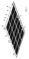
- FIG. 1 shows an electric heater as additional heating for a motor vehicle with a housing 2 comprising two identically designed housing parts 4, 6, which are joined to include a heating block 8 by latching.
- the housing parts 4, 6 each have a heating block 8 releasing housing opening 10 and are connected at its connection side with a flange 12, the electrical plug contacts for connection the heating block 8 and a surrounding of a control housing 14 control releases and holds.
- FIG. 1 shows the embodiment of the flow inlet side.
- the housing opening 10 of the housing part 4 is penetrated by five cross struts 16.
- the transverse struts 16 extend at right angles to the layers of the heating block 8. These layers are formed by heat-emitting elements in the form of radiator elements 18 and heat-generating elements 20 received therebetween.
- the heat-generating elements 20 each consist of a positioning frame 22 made of an electrically insulating material, which leaves a receiving opening 24 for receiving a respective PTC element 26.
- the position frames 22 also take on electrically conductive metal strips 28 in which rest on opposite sides of the PTC element 16 to these and energize them.
- insulation layers 30 are provided on the outer side of individual sheet metal strips 28 which electrically insulate the metal strips 28 energized with different polarity from the metallic radiator elements 18, so that individual heat-generating elements 20 are electrically limited from each other and can be controlled in a defined manner. It should be prevented that within the Heiblocks 8 different potentials are directly opposite. Because of this, it is possible, for example, to operate two heating stages of the heating block via a ground connection.
- Opposite longitudinal bars 32 of the frame-shaped housing 2 have latching openings 34 for receiving latching projections 36 of a cover 38 forming a contact protection.
- This cover 38 consists of an injection-molded cover frame 44, which is penetrated by frame longitudinal and cross-braces 40, 42.
- the cover 38 further comprises a plastic net 46, which is connected on both sides of the struts 40, 42 and the cover frame 44 forming plastic material by means of injection molding with this. Accordingly, the struts 40, 42 and the cover frame 44 are formed in the flow direction on both sides of the plastic mesh 46.
- cover 38 can be detachably connected to the housing 2.
- the latching projections 36 in the associated latching openings 34 introduced. Locking lugs formed on the latching projections 36 lock against the housing 2, so that the cover 38 is held captive on the housing 2.
- the plastic mesh 46 has in the in the FIGS. 1 and 2 shown embodiment, a mesh size such that a piece of wire with a nominal diameter of 1 mm can not pass through the plastic mesh 46 through to the elements 18, 20 of the heating block 8.
- the cumulative thickness of the transverse struts 16 and the cover 18 in particular in the region of the frame cross struts 42 results in a free distance between the surface of the heating block 8 and the plastic mesh 46 of about 6 mm.
- the plastic mesh 46 is additionally stiffened, so that a force acting against the plastic mesh 46 compressive force does not cause this can be down to the level of the heating block 8.
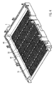
- FIGS. 3 to 5 Another embodiment is in the FIGS. 3 to 5 clarified. Identical components are provided with the same reference numerals with respect to the previously discussed embodiment. While the above with reference to the FIGS. 1 and 2 embodiment shown is particularly suitable for retrofitting existing electrical heaters, which is in the FIGS. 3 to 5 clarified embodiment created from the outset as inventive electric heater. Consequently, the plastic mesh 46 is formed as part of the housing part 4 and 6, respectively.
- FIG. 4 illustrates, in the second embodiment, the plastic mesh 46 is connected by encapsulation with the housing part 4 ausformenden material.
- the material forming the transverse struts 16 of the housing part 4 is also located here on both sides of the plastic net 46 and projects beyond it.
- the transverse struts 16 are formed with projecting cams 48 which leave between them a clearance 50 whose height (extension in a direction transverse to the layers of the stratified heating block) corresponds approximately to the thickness of the heat-generating elements 20, so that these between the cam 48 can be received (see. FIG. 5
- the cams 48 are also at a certain Deflection of the transverse struts 16 a sufficient distance between the plastic mesh 46 and the or the radiator elements 18 safely.
- the second embodiment according to the FIGS. 3 to 5 has only cross struts 16, it should be noted that the respective housing parts 4, 6 not only a strut arrangement with cross struts 16, but also such, as has been described above for the cover 38 and which has cross struts and longitudinal struts may have. Such a strut arrangement leads to a special stiffening of the housing opening 10 and largely prevents a deflection of the contact protection in the direction of the heating block. 8
- FIG. 5 results in the embodiment according to the FIGS. 3 to 5 the positioning frame 22 beyond the heating block 8, ie extended in the flow direction.
- the positioning frames 22 accordingly form spacer webs 52 which project beyond the heating block 8 on both sides. These spacer webs 52 cooperate with the two housing parts 4, 6 and keep the cross struts 16 at a distance from the heating block 8. Due to the large number of support points along the cross struts is not to be feared that they substantially bend in the direction of the heating block 8, for example in the case of an externally acting on the housing part 4 compressive force. It is - as if out FIG.
- the housing part 4 shows - to note that only the housing part 4 is provided with a plastic mesh 46, whereas the housing part 6 in otherwise identical configuration has no corresponding plastic mesh 46.
- the two housing parts 4, 6 can therefore be formed in injection molds identical geometry with the difference that in the one injection mold for producing the housing part 4 before the injection of the plastic component, the plastic mesh 46 is inserted as an insert.
- the dimension of the spacer webs 52 at right angles to the heating block 8 receiving level is chosen so that a distance A of between 4 and 8 mm between the surface of the heating block 8 and the contact protection 46 results.
- FIG. 6 shows a housing part 4 of another embodiment, which is formed substantially identical to the embodiment described above with the difference that are parallel to the transverse struts 16 on the inside of the housing part 4 spacer supports 54, which is continuous between the two longitudinal beams 32 with uniform Extend height.
- the height of the spacer supports 54 is so selected that the contact guard 46 is held at a predetermined distance from the heating block 8.
- the contact protection 46 is supported via the spacer support 54, in particular with the end faces of the positioning frames 22.
- spacing supports 54 can also be provided in combination with the spacer webs 52 of the positioning frames 22 in order to set a desired spacing between the plastic mesh 46 and the heating block 8 by means of spacer webs 52 and spacer supports 54 crossing at right angles.
- the end faces of the spacer webs 52 and / or the spacer supports 54 may be formed like a cam with intervening clearances, as has been described above with reference to the second embodiment.
Landscapes
- Engineering & Computer Science (AREA)
- Physics & Mathematics (AREA)
- Thermal Sciences (AREA)
- Mechanical Engineering (AREA)
- Chemical & Material Sciences (AREA)
- Combustion & Propulsion (AREA)
- General Engineering & Computer Science (AREA)
- Air-Conditioning For Vehicles (AREA)
- Resistance Heating (AREA)
- Control Of Resistance Heating (AREA)
Priority Applications (5)
| Application Number | Priority Date | Filing Date | Title |
|---|---|---|---|
| EP10015844.3A EP2466222B1 (fr) | 2010-12-20 | 2010-12-20 | Dispositif de chauffage électrique |
| JP2011275968A JP2012131482A (ja) | 2010-12-20 | 2011-12-16 | 電気加熱装置 |
| US13/327,872 US20120152931A1 (en) | 2010-12-20 | 2011-12-16 | Electrical heating device |
| CN201110430756.6A CN102548058B (zh) | 2010-12-20 | 2011-12-20 | 电气加热装置 |
| KR1020110137850A KR20120069589A (ko) | 2010-12-20 | 2011-12-20 | 전기 가열 장치 |
Applications Claiming Priority (1)
| Application Number | Priority Date | Filing Date | Title |
|---|---|---|---|
| EP10015844.3A EP2466222B1 (fr) | 2010-12-20 | 2010-12-20 | Dispositif de chauffage électrique |
Publications (2)
| Publication Number | Publication Date |
|---|---|
| EP2466222A1 true EP2466222A1 (fr) | 2012-06-20 |
| EP2466222B1 EP2466222B1 (fr) | 2013-06-05 |
Family
ID=43813177
Family Applications (1)
| Application Number | Title | Priority Date | Filing Date |
|---|---|---|---|
| EP10015844.3A Active EP2466222B1 (fr) | 2010-12-20 | 2010-12-20 | Dispositif de chauffage électrique |
Country Status (5)
| Country | Link |
|---|---|
| US (1) | US20120152931A1 (fr) |
| EP (1) | EP2466222B1 (fr) |
| JP (1) | JP2012131482A (fr) |
| KR (1) | KR20120069589A (fr) |
| CN (1) | CN102548058B (fr) |
Cited By (3)
| Publication number | Priority date | Publication date | Assignee | Title |
|---|---|---|---|---|
| WO2014000666A1 (fr) * | 2012-06-27 | 2014-01-03 | Shenzhen Byd Auto R&D Company Limited | Ensemble chauffant électrique à coefficient de température positif, dispositif chauffant électrique et véhicule électrique |
| CN103542528A (zh) * | 2012-07-13 | 2014-01-29 | 比亚迪股份有限公司 | 一种电加热装置以及电动车 |
| EP2806708A1 (fr) * | 2013-05-21 | 2014-11-26 | Behr France Rouffach SAS | Radiateur |
Families Citing this family (6)
| Publication number | Priority date | Publication date | Assignee | Title |
|---|---|---|---|---|
| KR20150025221A (ko) * | 2013-08-28 | 2015-03-10 | 현대자동차주식회사 | 차량용 히터 장치 |
| US9233595B2 (en) * | 2013-12-24 | 2016-01-12 | Hyundai Motor Company | Method of controlling heating of hybrid electric vehicle |
| US10709863B2 (en) | 2014-12-04 | 2020-07-14 | Koninklijke Philips N.V. | Patient circuit with adjustable length |
| JP6472650B2 (ja) * | 2014-12-08 | 2019-02-20 | 株式会社日本クライメイトシステムズ | 車両用空調装置の電気式ヒータ |
| US11098923B2 (en) * | 2016-03-31 | 2021-08-24 | Gd Midea Environment Appliances Mfg Co., Ltd. | Electric radiator |
| DE102018220858A1 (de) * | 2018-12-03 | 2020-06-04 | Eberspächer Catem Gmbh & Co. Kg | Elektrische Heizvorrichtung |
Citations (7)
| Publication number | Priority date | Publication date | Assignee | Title |
|---|---|---|---|---|
| DE4404345A1 (de) * | 1993-02-18 | 1994-08-25 | Valeo Thermique Habitacle | Elektrischer Heizradiator, insbesondere für den Fahrgastraum eines Kraftfahrzeuges |
| US5562844A (en) * | 1992-06-23 | 1996-10-08 | David & Baader - Dbk- Spezialfabrik Elektrischer Apparate Und Heizwiderstande Gmbh | Ptc heater radiator with frame members applying pressure to heaters |
| EP1621378A1 (fr) | 2004-07-28 | 2006-02-01 | Behr France Rouffach SAS | Dispositif de chauffage comprenant un élément chauffant, en particulier pour un véhicule |
| EP1731340A1 (fr) | 2005-06-07 | 2006-12-13 | Catem GmbH & Co. KG | Appareil de chauffage électrique |
| EP1768459A1 (fr) | 2005-09-23 | 2007-03-28 | Catem GmbH & Co. KG | Elément chauffant d'un dispositif de chauffage |
| EP2056036A1 (fr) * | 2007-10-31 | 2009-05-06 | Valeo Systemes Thermiques | Dispositif de chauffage électrique d'un flux d'air circulant a l'intérieur d'une installation de ventilation, de chauffage et/ou de climatisation d'un véhicule automobile |
| EP2161514A1 (fr) * | 2008-09-04 | 2010-03-10 | Behr France Rouffach SAS | Echangeur de chaleur |
Family Cites Families (1)
| Publication number | Priority date | Publication date | Assignee | Title |
|---|---|---|---|---|
| JPS5872837A (ja) * | 1981-10-26 | 1983-04-30 | Nissan Motor Co Ltd | 車両暖房用の燃焼式ヒ−タ |
-
2010
- 2010-12-20 EP EP10015844.3A patent/EP2466222B1/fr active Active
-
2011
- 2011-12-16 JP JP2011275968A patent/JP2012131482A/ja active Pending
- 2011-12-16 US US13/327,872 patent/US20120152931A1/en not_active Abandoned
- 2011-12-20 CN CN201110430756.6A patent/CN102548058B/zh active Active
- 2011-12-20 KR KR1020110137850A patent/KR20120069589A/ko not_active Application Discontinuation
Patent Citations (7)
| Publication number | Priority date | Publication date | Assignee | Title |
|---|---|---|---|---|
| US5562844A (en) * | 1992-06-23 | 1996-10-08 | David & Baader - Dbk- Spezialfabrik Elektrischer Apparate Und Heizwiderstande Gmbh | Ptc heater radiator with frame members applying pressure to heaters |
| DE4404345A1 (de) * | 1993-02-18 | 1994-08-25 | Valeo Thermique Habitacle | Elektrischer Heizradiator, insbesondere für den Fahrgastraum eines Kraftfahrzeuges |
| EP1621378A1 (fr) | 2004-07-28 | 2006-02-01 | Behr France Rouffach SAS | Dispositif de chauffage comprenant un élément chauffant, en particulier pour un véhicule |
| EP1731340A1 (fr) | 2005-06-07 | 2006-12-13 | Catem GmbH & Co. KG | Appareil de chauffage électrique |
| EP1768459A1 (fr) | 2005-09-23 | 2007-03-28 | Catem GmbH & Co. KG | Elément chauffant d'un dispositif de chauffage |
| EP2056036A1 (fr) * | 2007-10-31 | 2009-05-06 | Valeo Systemes Thermiques | Dispositif de chauffage électrique d'un flux d'air circulant a l'intérieur d'une installation de ventilation, de chauffage et/ou de climatisation d'un véhicule automobile |
| EP2161514A1 (fr) * | 2008-09-04 | 2010-03-10 | Behr France Rouffach SAS | Echangeur de chaleur |
Cited By (5)
| Publication number | Priority date | Publication date | Assignee | Title |
|---|---|---|---|---|
| WO2014000666A1 (fr) * | 2012-06-27 | 2014-01-03 | Shenzhen Byd Auto R&D Company Limited | Ensemble chauffant électrique à coefficient de température positif, dispositif chauffant électrique et véhicule électrique |
| CN103542528A (zh) * | 2012-07-13 | 2014-01-29 | 比亚迪股份有限公司 | 一种电加热装置以及电动车 |
| CN103542528B (zh) * | 2012-07-13 | 2015-04-22 | 比亚迪股份有限公司 | 一种电加热装置以及电动车 |
| EP2806708A1 (fr) * | 2013-05-21 | 2014-11-26 | Behr France Rouffach SAS | Radiateur |
| EP2806707A1 (fr) * | 2013-05-21 | 2014-11-26 | Behr France Rouffach SAS | Radiateur |
Also Published As
| Publication number | Publication date |
|---|---|
| CN102548058A (zh) | 2012-07-04 |
| JP2012131482A (ja) | 2012-07-12 |
| CN102548058B (zh) | 2016-08-17 |
| US20120152931A1 (en) | 2012-06-21 |
| EP2466222B1 (fr) | 2013-06-05 |
| KR20120069589A (ko) | 2012-06-28 |
Similar Documents
| Publication | Publication Date | Title |
|---|---|---|
| EP2466222B1 (fr) | Dispositif de chauffage électrique | |
| EP2608632B1 (fr) | Dispositif de chauffage électrique et cadre associé | |
| EP2607121B2 (fr) | Dispositif de chauffage électrique, en particulier pour un véhicule automobile | |
| EP1467599B1 (fr) | Dispositif pour l'admission des éléments de chauffe en céramique et procédé pour la production de tels | |
| DE2625515A1 (de) | Heizvorrichtung fuer gase oder fluessigkeiten | |
| EP0333906B1 (fr) | Résistance chauffante à coefficient de température positif | |
| EP1910160B1 (fr) | Poignee | |
| DE102009031890A1 (de) | Heizvorrichtung | |
| EP2266823B1 (fr) | Dispositif de chauffage électrique | |
| DE10333451A1 (de) | Vorrichtung zur Aufnahme von Keramik-Heizelementen und Verfahren zur Herstellung einer solchen | |
| EP0743804B1 (fr) | Elément chauffant | |
| DE112006000165T5 (de) | PTC-Stangenanordnung und Vorwärmer welcher eine solche umfasst | |
| EP2171808B1 (fr) | Profilé isolant pour rail conducteur multipolaire | |
| DE102012222364A1 (de) | Steckverbinder und Vorrichtung mit einem solchen Steckverbinder | |
| DE102012011903B4 (de) | Elektrische Heizvorrichtung | |
| DE102012013828B4 (de) | Massive Stromsammelschiene mit im Wesentlichen rechtwinkligem Querschnitt, Untereinheit und System mit einer solchen Stromsammelschiene | |
| DE10316908A1 (de) | Heizvorrichtung | |
| EP2056649B1 (fr) | Support pour un dispositif de chauffage électrique et dispositif de chauffage électrique ainsi que procédé de fabrication | |
| WO2020126881A1 (fr) | Cadre de retenue pour un connecteur électrique | |
| DE202017102071U1 (de) | Lastwiderstand und Chopper-Widerstand mit Lastwiderstand | |
| EP0289447B1 (fr) | Dispositif de sectionnement pour rails à courant élevé | |
| DE202015105147U1 (de) | Kunststoffabstandhalter für Isolierglasscheiben und dergleichen | |
| EP2268103B1 (fr) | Dispositif de chauffage électrique | |
| EP1858385A1 (fr) | Grille-pain | |
| EP3956550A1 (fr) | Dispositif de traitement de gaz d'échappement et véhicule |
Legal Events
| Date | Code | Title | Description |
|---|---|---|---|
| PUAI | Public reference made under article 153(3) epc to a published international application that has entered the european phase |
Free format text: ORIGINAL CODE: 0009012 |
|
| 17P | Request for examination filed |
Effective date: 20110708 |
|
| AK | Designated contracting states |
Kind code of ref document: A1 Designated state(s): AL AT BE BG CH CY CZ DE DK EE ES FI FR GB GR HR HU IE IS IT LI LT LU LV MC MK MT NL NO PL PT RO RS SE SI SK SM TR |
|
| AX | Request for extension of the european patent |
Extension state: BA ME |
|
| REG | Reference to a national code |
Ref country code: DE Ref legal event code: R079 Ref document number: 502010003522 Country of ref document: DE Free format text: PREVIOUS MAIN CLASS: F24H0003040000 Ipc: F24H0009180000 |
|
| RIC1 | Information provided on ipc code assigned before grant |
Ipc: F24H 9/18 20060101AFI20121129BHEP Ipc: F24H 3/04 20060101ALI20121129BHEP Ipc: F24H 9/20 20060101ALI20121129BHEP |
|
| GRAP | Despatch of communication of intention to grant a patent |
Free format text: ORIGINAL CODE: EPIDOSNIGR1 |
|
| GRAS | Grant fee paid |
Free format text: ORIGINAL CODE: EPIDOSNIGR3 |
|
| GRAA | (expected) grant |
Free format text: ORIGINAL CODE: 0009210 |
|
| AK | Designated contracting states |
Kind code of ref document: B1 Designated state(s): AL AT BE BG CH CY CZ DE DK EE ES FI FR GB GR HR HU IE IS IT LI LT LU LV MC MK MT NL NO PL PT RO RS SE SI SK SM TR |
|
| REG | Reference to a national code |
Ref country code: GB Ref legal event code: FG4D Free format text: NOT ENGLISH |
|
| REG | Reference to a national code |
Ref country code: CH Ref legal event code: EP |
|
| REG | Reference to a national code |
Ref country code: AT Ref legal event code: REF Ref document number: 615888 Country of ref document: AT Kind code of ref document: T Effective date: 20130615 |
|
| REG | Reference to a national code |
Ref country code: IE Ref legal event code: FG4D Free format text: LANGUAGE OF EP DOCUMENT: GERMAN |
|
| REG | Reference to a national code |
Ref country code: DE Ref legal event code: R096 Ref document number: 502010003522 Country of ref document: DE Effective date: 20130801 |
|
| PG25 | Lapsed in a contracting state [announced via postgrant information from national office to epo] |
Ref country code: GR Free format text: LAPSE BECAUSE OF FAILURE TO SUBMIT A TRANSLATION OF THE DESCRIPTION OR TO PAY THE FEE WITHIN THE PRESCRIBED TIME-LIMIT Effective date: 20130906 Ref country code: ES Free format text: LAPSE BECAUSE OF FAILURE TO SUBMIT A TRANSLATION OF THE DESCRIPTION OR TO PAY THE FEE WITHIN THE PRESCRIBED TIME-LIMIT Effective date: 20130916 Ref country code: NO Free format text: LAPSE BECAUSE OF FAILURE TO SUBMIT A TRANSLATION OF THE DESCRIPTION OR TO PAY THE FEE WITHIN THE PRESCRIBED TIME-LIMIT Effective date: 20130905 Ref country code: FI Free format text: LAPSE BECAUSE OF FAILURE TO SUBMIT A TRANSLATION OF THE DESCRIPTION OR TO PAY THE FEE WITHIN THE PRESCRIBED TIME-LIMIT Effective date: 20130605 Ref country code: SI Free format text: LAPSE BECAUSE OF FAILURE TO SUBMIT A TRANSLATION OF THE DESCRIPTION OR TO PAY THE FEE WITHIN THE PRESCRIBED TIME-LIMIT Effective date: 20130605 Ref country code: LT Free format text: LAPSE BECAUSE OF FAILURE TO SUBMIT A TRANSLATION OF THE DESCRIPTION OR TO PAY THE FEE WITHIN THE PRESCRIBED TIME-LIMIT Effective date: 20130605 Ref country code: SE Free format text: LAPSE BECAUSE OF FAILURE TO SUBMIT A TRANSLATION OF THE DESCRIPTION OR TO PAY THE FEE WITHIN THE PRESCRIBED TIME-LIMIT Effective date: 20130605 |
|
| REG | Reference to a national code |
Ref country code: NL Ref legal event code: VDEP Effective date: 20130605 |
|
| REG | Reference to a national code |
Ref country code: LT Ref legal event code: MG4D |
|
| PG25 | Lapsed in a contracting state [announced via postgrant information from national office to epo] |
Ref country code: RS Free format text: LAPSE BECAUSE OF FAILURE TO SUBMIT A TRANSLATION OF THE DESCRIPTION OR TO PAY THE FEE WITHIN THE PRESCRIBED TIME-LIMIT Effective date: 20130605 Ref country code: BG Free format text: LAPSE BECAUSE OF FAILURE TO SUBMIT A TRANSLATION OF THE DESCRIPTION OR TO PAY THE FEE WITHIN THE PRESCRIBED TIME-LIMIT Effective date: 20130905 Ref country code: HR Free format text: LAPSE BECAUSE OF FAILURE TO SUBMIT A TRANSLATION OF THE DESCRIPTION OR TO PAY THE FEE WITHIN THE PRESCRIBED TIME-LIMIT Effective date: 20130605 |
|
| PG25 | Lapsed in a contracting state [announced via postgrant information from national office to epo] |
Ref country code: LV Free format text: LAPSE BECAUSE OF FAILURE TO SUBMIT A TRANSLATION OF THE DESCRIPTION OR TO PAY THE FEE WITHIN THE PRESCRIBED TIME-LIMIT Effective date: 20130605 |
|
| PG25 | Lapsed in a contracting state [announced via postgrant information from national office to epo] |
Ref country code: SK Free format text: LAPSE BECAUSE OF FAILURE TO SUBMIT A TRANSLATION OF THE DESCRIPTION OR TO PAY THE FEE WITHIN THE PRESCRIBED TIME-LIMIT Effective date: 20130605 Ref country code: CZ Free format text: LAPSE BECAUSE OF FAILURE TO SUBMIT A TRANSLATION OF THE DESCRIPTION OR TO PAY THE FEE WITHIN THE PRESCRIBED TIME-LIMIT Effective date: 20130605 Ref country code: PT Free format text: LAPSE BECAUSE OF FAILURE TO SUBMIT A TRANSLATION OF THE DESCRIPTION OR TO PAY THE FEE WITHIN THE PRESCRIBED TIME-LIMIT Effective date: 20131007 Ref country code: IS Free format text: LAPSE BECAUSE OF FAILURE TO SUBMIT A TRANSLATION OF THE DESCRIPTION OR TO PAY THE FEE WITHIN THE PRESCRIBED TIME-LIMIT Effective date: 20131005 Ref country code: EE Free format text: LAPSE BECAUSE OF FAILURE TO SUBMIT A TRANSLATION OF THE DESCRIPTION OR TO PAY THE FEE WITHIN THE PRESCRIBED TIME-LIMIT Effective date: 20130605 |
|
| PG25 | Lapsed in a contracting state [announced via postgrant information from national office to epo] |
Ref country code: PL Free format text: LAPSE BECAUSE OF FAILURE TO SUBMIT A TRANSLATION OF THE DESCRIPTION OR TO PAY THE FEE WITHIN THE PRESCRIBED TIME-LIMIT Effective date: 20130605 Ref country code: RO Free format text: LAPSE BECAUSE OF FAILURE TO SUBMIT A TRANSLATION OF THE DESCRIPTION OR TO PAY THE FEE WITHIN THE PRESCRIBED TIME-LIMIT Effective date: 20130605 Ref country code: NL Free format text: LAPSE BECAUSE OF FAILURE TO SUBMIT A TRANSLATION OF THE DESCRIPTION OR TO PAY THE FEE WITHIN THE PRESCRIBED TIME-LIMIT Effective date: 20130605 |
|
| PLBE | No opposition filed within time limit |
Free format text: ORIGINAL CODE: 0009261 |
|
| STAA | Information on the status of an ep patent application or granted ep patent |
Free format text: STATUS: NO OPPOSITION FILED WITHIN TIME LIMIT |
|
| PG25 | Lapsed in a contracting state [announced via postgrant information from national office to epo] |
Ref country code: DK Free format text: LAPSE BECAUSE OF FAILURE TO SUBMIT A TRANSLATION OF THE DESCRIPTION OR TO PAY THE FEE WITHIN THE PRESCRIBED TIME-LIMIT Effective date: 20130605 |
|
| 26N | No opposition filed |
Effective date: 20140306 |
|
| REG | Reference to a national code |
Ref country code: DE Ref legal event code: R097 Ref document number: 502010003522 Country of ref document: DE Effective date: 20140306 |
|
| BERE | Be: lapsed |
Owner name: EBERSPACHER CATEM G.M.B.H. & CO. KG Effective date: 20131231 |
|
| PG25 | Lapsed in a contracting state [announced via postgrant information from national office to epo] |
Ref country code: MC Free format text: LAPSE BECAUSE OF FAILURE TO SUBMIT A TRANSLATION OF THE DESCRIPTION OR TO PAY THE FEE WITHIN THE PRESCRIBED TIME-LIMIT Effective date: 20130605 |
|
| PG25 | Lapsed in a contracting state [announced via postgrant information from national office to epo] |
Ref country code: LU Free format text: LAPSE BECAUSE OF FAILURE TO SUBMIT A TRANSLATION OF THE DESCRIPTION OR TO PAY THE FEE WITHIN THE PRESCRIBED TIME-LIMIT Effective date: 20131220 |
|
| REG | Reference to a national code |
Ref country code: IE Ref legal event code: MM4A |
|
| PG25 | Lapsed in a contracting state [announced via postgrant information from national office to epo] |
Ref country code: IE Free format text: LAPSE BECAUSE OF NON-PAYMENT OF DUE FEES Effective date: 20131220 Ref country code: BE Free format text: LAPSE BECAUSE OF NON-PAYMENT OF DUE FEES Effective date: 20131231 |
|
| PG25 | Lapsed in a contracting state [announced via postgrant information from national office to epo] |
Ref country code: SM Free format text: LAPSE BECAUSE OF FAILURE TO SUBMIT A TRANSLATION OF THE DESCRIPTION OR TO PAY THE FEE WITHIN THE PRESCRIBED TIME-LIMIT Effective date: 20130605 |
|
| PG25 | Lapsed in a contracting state [announced via postgrant information from national office to epo] |
Ref country code: CY Free format text: LAPSE BECAUSE OF FAILURE TO SUBMIT A TRANSLATION OF THE DESCRIPTION OR TO PAY THE FEE WITHIN THE PRESCRIBED TIME-LIMIT Effective date: 20130605 Ref country code: TR Free format text: LAPSE BECAUSE OF FAILURE TO SUBMIT A TRANSLATION OF THE DESCRIPTION OR TO PAY THE FEE WITHIN THE PRESCRIBED TIME-LIMIT Effective date: 20130605 |
|
| PG25 | Lapsed in a contracting state [announced via postgrant information from national office to epo] |
Ref country code: HU Free format text: LAPSE BECAUSE OF FAILURE TO SUBMIT A TRANSLATION OF THE DESCRIPTION OR TO PAY THE FEE WITHIN THE PRESCRIBED TIME-LIMIT; INVALID AB INITIO Effective date: 20101220 Ref country code: MK Free format text: LAPSE BECAUSE OF FAILURE TO SUBMIT A TRANSLATION OF THE DESCRIPTION OR TO PAY THE FEE WITHIN THE PRESCRIBED TIME-LIMIT Effective date: 20130605 |
|
| REG | Reference to a national code |
Ref country code: CH Ref legal event code: PL |
|
| GBPC | Gb: european patent ceased through non-payment of renewal fee |
Effective date: 20141220 |
|
| PG25 | Lapsed in a contracting state [announced via postgrant information from national office to epo] |
Ref country code: MT Free format text: LAPSE BECAUSE OF FAILURE TO SUBMIT A TRANSLATION OF THE DESCRIPTION OR TO PAY THE FEE WITHIN THE PRESCRIBED TIME-LIMIT Effective date: 20130605 |
|
| PG25 | Lapsed in a contracting state [announced via postgrant information from national office to epo] |
Ref country code: GB Free format text: LAPSE BECAUSE OF NON-PAYMENT OF DUE FEES Effective date: 20141220 Ref country code: CH Free format text: LAPSE BECAUSE OF NON-PAYMENT OF DUE FEES Effective date: 20141231 Ref country code: LI Free format text: LAPSE BECAUSE OF NON-PAYMENT OF DUE FEES Effective date: 20141231 |
|
| REG | Reference to a national code |
Ref country code: FR Ref legal event code: PLFP Year of fee payment: 6 |
|
| REG | Reference to a national code |
Ref country code: FR Ref legal event code: PLFP Year of fee payment: 7 |
|
| REG | Reference to a national code |
Ref country code: AT Ref legal event code: MM01 Ref document number: 615888 Country of ref document: AT Kind code of ref document: T Effective date: 20151220 |
|
| PG25 | Lapsed in a contracting state [announced via postgrant information from national office to epo] |
Ref country code: AT Free format text: LAPSE BECAUSE OF NON-PAYMENT OF DUE FEES Effective date: 20151220 |
|
| REG | Reference to a national code |
Ref country code: FR Ref legal event code: PLFP Year of fee payment: 8 |
|
| PG25 | Lapsed in a contracting state [announced via postgrant information from national office to epo] |
Ref country code: AL Free format text: LAPSE BECAUSE OF FAILURE TO SUBMIT A TRANSLATION OF THE DESCRIPTION OR TO PAY THE FEE WITHIN THE PRESCRIBED TIME-LIMIT Effective date: 20130605 |
|
| REG | Reference to a national code |
Ref country code: FR Ref legal event code: PLFP Year of fee payment: 12 |
|
| PGFP | Annual fee paid to national office [announced via postgrant information from national office to epo] |
Ref country code: FR Payment date: 20211220 Year of fee payment: 12 |
|
| PGFP | Annual fee paid to national office [announced via postgrant information from national office to epo] |
Ref country code: IT Payment date: 20211230 Year of fee payment: 12 |
|
| PG25 | Lapsed in a contracting state [announced via postgrant information from national office to epo] |
Ref country code: FR Free format text: LAPSE BECAUSE OF NON-PAYMENT OF DUE FEES Effective date: 20221231 |
|
| PG25 | Lapsed in a contracting state [announced via postgrant information from national office to epo] |
Ref country code: IT Free format text: LAPSE BECAUSE OF NON-PAYMENT OF DUE FEES Effective date: 20221220 |
|
| PGFP | Annual fee paid to national office [announced via postgrant information from national office to epo] |
Ref country code: DE Payment date: 20231214 Year of fee payment: 14 |