EP1762522B1 - Bogenverarbeitungsgerät - Google Patents
Bogenverarbeitungsgerät Download PDFInfo
- Publication number
- EP1762522B1 EP1762522B1 EP06120485.5A EP06120485A EP1762522B1 EP 1762522 B1 EP1762522 B1 EP 1762522B1 EP 06120485 A EP06120485 A EP 06120485A EP 1762522 B1 EP1762522 B1 EP 1762522B1
- Authority
- EP
- European Patent Office
- Prior art keywords
- sheet
- lateral register
- sheets
- stack
- correction unit
- Prior art date
- Legal status (The legal status is an assumption and is not a legal conclusion. Google has not performed a legal analysis and makes no representation as to the accuracy of the status listed.)
- Active
Links
- 238000012545 processing Methods 0.000 title claims description 38
- 230000007257 malfunction Effects 0.000 claims description 13
- 230000003213 activating effect Effects 0.000 claims description 3
- 238000012937 correction Methods 0.000 description 119
- 238000000034 method Methods 0.000 description 64
- 238000006073 displacement reaction Methods 0.000 description 18
- 230000015572 biosynthetic process Effects 0.000 description 4
- 238000010586 diagram Methods 0.000 description 4
- 239000011521 glass Substances 0.000 description 4
- 238000012546 transfer Methods 0.000 description 4
- 238000013459 approach Methods 0.000 description 2
- 238000004891 communication Methods 0.000 description 1
- 230000002093 peripheral effect Effects 0.000 description 1
Images


Classifications
-
- B—PERFORMING OPERATIONS; TRANSPORTING
- B65—CONVEYING; PACKING; STORING; HANDLING THIN OR FILAMENTARY MATERIAL
- B65H—HANDLING THIN OR FILAMENTARY MATERIAL, e.g. SHEETS, WEBS, CABLES
- B65H9/00—Registering, e.g. orientating, articles; Devices therefor
- B65H9/10—Pusher and like movable registers; Pusher or gripper devices which move articles into registered position
- B65H9/101—Pusher and like movable registers; Pusher or gripper devices which move articles into registered position acting on the edge of the article
-
- B—PERFORMING OPERATIONS; TRANSPORTING
- B42—BOOKBINDING; ALBUMS; FILES; SPECIAL PRINTED MATTER
- B42C—BOOKBINDING
- B42C1/00—Collating or gathering sheets combined with processes for permanently attaching together sheets or signatures or for interposing inserts
- B42C1/12—Machines for both collating or gathering and permanently attaching together the sheets or signatures
-
- B—PERFORMING OPERATIONS; TRANSPORTING
- B65—CONVEYING; PACKING; STORING; HANDLING THIN OR FILAMENTARY MATERIAL
- B65H—HANDLING THIN OR FILAMENTARY MATERIAL, e.g. SHEETS, WEBS, CABLES
- B65H29/00—Delivering or advancing articles from machines; Advancing articles to or into piles
- B65H29/12—Delivering or advancing articles from machines; Advancing articles to or into piles by means of the nip between two, or between two sets of, moving tapes or bands or rollers
-
- B—PERFORMING OPERATIONS; TRANSPORTING
- B65—CONVEYING; PACKING; STORING; HANDLING THIN OR FILAMENTARY MATERIAL
- B65H—HANDLING THIN OR FILAMENTARY MATERIAL, e.g. SHEETS, WEBS, CABLES
- B65H31/00—Pile receivers
- B65H31/34—Apparatus for squaring-up piled articles
-
- B—PERFORMING OPERATIONS; TRANSPORTING
- B65—CONVEYING; PACKING; STORING; HANDLING THIN OR FILAMENTARY MATERIAL
- B65H—HANDLING THIN OR FILAMENTARY MATERIAL, e.g. SHEETS, WEBS, CABLES
- B65H31/00—Pile receivers
- B65H31/34—Apparatus for squaring-up piled articles
- B65H31/38—Apparatus for vibrating or knocking the pile during piling
-
- B—PERFORMING OPERATIONS; TRANSPORTING
- B65—CONVEYING; PACKING; STORING; HANDLING THIN OR FILAMENTARY MATERIAL
- B65H—HANDLING THIN OR FILAMENTARY MATERIAL, e.g. SHEETS, WEBS, CABLES
- B65H2220/00—Function indicators
- B65H2220/02—Function indicators indicating an entity which is controlled, adjusted or changed by a control process, i.e. output
-
- B—PERFORMING OPERATIONS; TRANSPORTING
- B65—CONVEYING; PACKING; STORING; HANDLING THIN OR FILAMENTARY MATERIAL
- B65H—HANDLING THIN OR FILAMENTARY MATERIAL, e.g. SHEETS, WEBS, CABLES
- B65H2220/00—Function indicators
- B65H2220/11—Function indicators indicating that the input or output entities exclusively relate to machine elements
-
- B—PERFORMING OPERATIONS; TRANSPORTING
- B65—CONVEYING; PACKING; STORING; HANDLING THIN OR FILAMENTARY MATERIAL
- B65H—HANDLING THIN OR FILAMENTARY MATERIAL, e.g. SHEETS, WEBS, CABLES
- B65H2301/00—Handling processes for sheets or webs
- B65H2301/30—Orientation, displacement, position of the handled material
- B65H2301/36—Positioning; Changing position
- B65H2301/361—Positioning; Changing position during displacement
- B65H2301/3613—Lateral positioning
-
- B—PERFORMING OPERATIONS; TRANSPORTING
- B65—CONVEYING; PACKING; STORING; HANDLING THIN OR FILAMENTARY MATERIAL
- B65H—HANDLING THIN OR FILAMENTARY MATERIAL, e.g. SHEETS, WEBS, CABLES
- B65H2301/00—Handling processes for sheets or webs
- B65H2301/30—Orientation, displacement, position of the handled material
- B65H2301/36—Positioning; Changing position
- B65H2301/362—Positioning; Changing position of stationary material
- B65H2301/3621—Positioning; Changing position of stationary material perpendicularly to a first direction in which the material is already in registered position
-
- B—PERFORMING OPERATIONS; TRANSPORTING
- B65—CONVEYING; PACKING; STORING; HANDLING THIN OR FILAMENTARY MATERIAL
- B65H—HANDLING THIN OR FILAMENTARY MATERIAL, e.g. SHEETS, WEBS, CABLES
- B65H2301/00—Handling processes for sheets or webs
- B65H2301/30—Orientation, displacement, position of the handled material
- B65H2301/36—Positioning; Changing position
- B65H2301/363—Positioning; Changing position of material in pile
-
- B—PERFORMING OPERATIONS; TRANSPORTING
- B65—CONVEYING; PACKING; STORING; HANDLING THIN OR FILAMENTARY MATERIAL
- B65H—HANDLING THIN OR FILAMENTARY MATERIAL, e.g. SHEETS, WEBS, CABLES
- B65H2404/00—Parts for transporting or guiding the handled material
- B65H2404/10—Rollers
- B65H2404/14—Roller pairs
- B65H2404/142—Roller pairs arranged on movable frame
- B65H2404/1424—Roller pairs arranged on movable frame moving in parallel to their axis
-
- B—PERFORMING OPERATIONS; TRANSPORTING
- B65—CONVEYING; PACKING; STORING; HANDLING THIN OR FILAMENTARY MATERIAL
- B65H—HANDLING THIN OR FILAMENTARY MATERIAL, e.g. SHEETS, WEBS, CABLES
- B65H2511/00—Dimensions; Position; Numbers; Identification; Occurrences
- B65H2511/20—Location in space
Definitions
- the present invention relates to a sheet processing apparatus.
- Some image forming devices such as photocopiers, printers, facsimiles, and multifunctional peripheral devices are provided with a sheet processing apparatus that processes sheets discharged from the body of the image forming apparatus.
- the sheet processing apparatus staples the sheets.
- Some of such sheet processing apparatuses load the discharged sheets on a process tray and align the sheets before stapling
- Japanese Patent Laid-Open No. 2.004-51256 discloses an image forming apparatus whose body is provided with a lateral register correction unit that detects the side edge in a direction perpendicular to the sheet conveying direction (hereinafter referred to as "width direction") of a sheet and moves the sheet in the width direction so as to correct the position in the width direction of the sheet.
- the term "lateral register correction” here means position correction in the width direction of a sheet.
- the lateral register position of a sheet can be aligned with the image forming position.
- the sheet position can be corrected without reducing the productivity of the image forming apparatus.
- the sheet can be discharged from the body of the image forming apparatus to the sheet processing apparatus with the position of the side edge in the width direction of the sheet aligned.
- lateral register displacement that is to say, displacement in the width direction occurs. Therefore, when sheets are processed, a sheet alignment operation is performed on a process tray on which sheets are temporarily loaded. That is to say, it is necessary to perform a sheet alignment operation on the process tray even after the lateral register correction is performed in the body of the image forming apparatus.
- sheet stacks are offset copy by copy.
- the sheet stacks are thereby loaded on the discharge tray, being offset stack by stack.
- the sheet stacks are sorted.
- US 2003/0052446 A1 discloses a sheet processing apparatus as claimed in the pre-characterizing portion of claim 1 herein.
- US2002/0079642 discloses a sheet medium processing apparatus in which a sheet bundle is loaded at a single central location.
- the apparatus includes a first arranging member and a second arranging member, which are positioned on either side of the loaded sheet bundle, the first at a position to which the sheet bundle is to be moved and the second, on the other side of the sheet bundle and closer thereto than the first.
- the second arranging member then moves the sheet bundle into contact with the first arranging member and in doing so shifts the sheet bundle from the central location. If a subsequent bundle of sheets is loaded the actions of the first and second arranging members is reversed, such that the second bundle is shifted to the opposite side of the central location from the first bundle.
- the present invention provides a sheet processing apparatus that can achieve high productivity.
- the present invention can reduce the time of sheet alignment operation performed by the aligning members and can achieve high productivity.
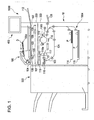
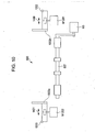
- FIG. 1 is a sectional view of a photocopier that is an example of an image forming apparatus having a sheet processing apparatus according to a first embodiment of he present invention.
- reference numeral 1000 denotes a photocopier.
- the photocopier 1000 includes a photocopier body 10, a finisher 500 that is a sheet processing apparatus, and a scanner 200 disposed on the top of the photocopier body 10.
- the scanner 200 scans documents.
- the scanner 200 includes a document feeder 100, a scanner unit 104, mirrors 105 to 107, a lens 108, and an image sensor 109.
- the scanner 200 scans documents D
- the documents D are placed on the tray 100a with the side to be copied face up.
- the document feeder 100 conveys the documents D from the initial page one by one to the left (in the direction of the arrow in the figure). After passing along a curved path, the documents D are conveyed on a platen glass 102 from the left to the right and then discharged onto a discharged paper tray 112.
- the scanner unit 104 When scanning the documents D being conveyed by the document feeder 100, the scanner unit 104 is held at a predetermined position. The documents,D pass over the scanner unit 104 from the left to the right so as to be scanned.
- a lamp 103 of the scanner unit 104 irradiates the documents D with light.
- the reflection is guided to the image sensor 109 via the mirrors 105 to 107 and the lens 108.
- the image sensor 109 scans the image data of each document D line by line. After a predetermined image data processing is performed in an image signal control part 202 shown in FIG. 3 , the image data is sent to an exposure control part 110.
- the scanning of the documents can also be performed by stopping a document D being conveyed by the document feeder 100 on the platen glass 102 and then moving the scanner unit 104 from the left to the right.
- the user When a user scans a document without using the document feeder 100, the user lifts the document feeder 100 and places the document on the platen glass 102 so as to scan the document.
- the photocopier body 10 includes a sheet feeding part 1004 and an image forming part 1003.
- the sheet feeding part 1004 feeds sheets P contained in cassettes 114 and 115.
- the image forming part 1003 forms images on the sheets P fed by the sheet feeding part 1002.
- the image forming part 1003 includes a photosensitive drum 111, a developer 113, and a transfer charger 116.
- the exposure control part 110 irradiates the photosensitive drum 111 with laser light, thereby forming a latent image on the photosensitive drum 111.
- the latent image is changed into a visible image, that is to say, a toner image by the developer 113.
- A. fixing unit 117 and a discharge roller pair 118 are disposed on the downstream side of the image forming part 1003.
- Reference numeral 400 denotes an operation display provided on the top of the photocopier body 10.
- the operation display 400 includes a plurality of keys for setting various functions concerning image formation and a display part that displays the information showing the setting.
- the image sensor 109 of the scanner 200 scans the image data of the document D. After a predetermined image data processing is performed in the image signal control part 202, the image data is sent to the exposure control part 110. Next, the exposure control part 110 outputs laser light according to the image signal.
- This laser light is scanned by a polygon mirror 110a, and the photosensitive drum 111 is irradiated with the laser light. In this way, an electrostatic latent image according to the scanned laser light is formed on the photosensitive drum 111. Next, the electrostatic latent image formed on the photosensitive drum 111 is changed into a visible image, that is to say, a toner image by the developer 113.
- a sheet P is conveyed from one of the cassettes 114 and 115, a manual paper feeder 125, and a both side conveyance path 124 to a transfer part, which includes the photosensitive drum 111 and the transfer charger 116.
- a transfer part which includes the photosensitive drum 111 and the transfer charger 116.
- the toner image on the photosensitive drum 111 is transferred onto the sheet P.
- the transferred toner image is fixed to the sheet P in the fixing unit 117.
- the sheet P with the fixed toner image is discharged into the finisher 500 by the discharge roller pair 118.
- a flapper 121 guides the sheet P to a path 122 after the sheet P has passed through the fixing unit 117. Next, after the trailing edge of the sheet P has left the flapper 121, the sheet P is conveyed backward. The sheet P is guided to the discharge roller pair 118 by the flapper 121 and than discharged from the photocopier body 10.
- the sheet P is discharged from the photocopier body 10 with the toner image side face down.
- Such mode of discharge is called "reverse discharge.” Since sheets P are discharged face down by the reverse discharge, when image formation is performed from the initial page, for example, when image formation is performed using the document feeder 100, the sheets P are ordered by page. In addition, in the case of image formation based on image data from a computer, sheets P are also ordered by page.
- the sheet P When images are formed on both sides of a sheet P, the sheet P is guided from the fixing unit 117 straight to the discharge roller pair 118. Just after the trailing edge of the sheet P has left the flapper 121, the sheet P is conveyed backward and guided by the flapper 121 to the path 122 and the both side conveyance path 124.
- the sheets discharged from the photocopier body 10 are then taken in the finisher 500.
- the finisher 500 is a sheet processing apparatus that staples or binds the sheets on which images are formed.
- the finisher 500 takes in sheets from the photocopier body 10 and performs various processes such as a process to align the sheets and form a sheet stack, a sort process, a non-sort process, a stapling process to place staples at the trailing edge of the sheet stack, and a binding process.
- the finisher 500 includes a stapling part 600 and a binding part 800.
- the stapling part 600 staples a sheet stack.
- the binding part 800 folds a sheet stack in half and binds them.
- the stapling part 600 includes a process tray (sheet processing tray) 630 and a pair of aligning plates (aligning members) 1002.
- the process tray 630 is loaded with a sheet stack.
- the aligning plates 1002 align the sheet stack on the process tray 630 in the width direction.
- the stapling part 600 further includes a stapler 601 that staples the sheet stack.
- the binding part 800 includes a binding entrance sensor 831, two pairs of staplers 810, and a binding intermediate tray (hereinafter referred to as "binding tray") 830 in which sheets are loaded.
- the binding tray 830 is provided with an intermediate roller 803 and a movable sheet-positioning member 816.
- An anvil 811 is provided opposite the two pairs of staplers 810.
- the staplers 810 staples a sheet stack in the binding tray 830 in cooperation with the anvil 811.
- a folding roller pair 804 and a pushing member 815 are provided on the downstream side of the staplers 810.
- the pushing member 815 is opposite the folding roller pair 804.
- the pushing member 815 pushes the sheet stack in the binding tray 830 into the folding roller pair 804.
- a discharged paper sensor 832 is provided on the downstream side of a conveying roller pair 805.
- the finisher 500 further includes an entrance roller pair 502 for taking in the sheets conveyed from the photocopier body 10.
- An entrance sensor 531 is provided between the entrance roller pair 502 and a conveying roller pair 503.
- a lateral register correction unit 1001 is provided between the conveying roller pair 503 and a buffer roller 505.
- the lateral register correction unit 1001 operates in the shift sort mode in which discharged sheet stacks are offset.
- the lateral register correction unit 1001 is a shift conveying unit that conveys a sheet, shifting the sheet to a predetermined position in the width direction.
- the lateral register correction unit 1001 corrects the lateral registration of all sheets taken in the finisher 500 and conveys the sheets, shifting the sheets to a predetermined position in the width direction.
- the lateral register correction unit 1001 includes conveying rollers 1101a and 1102a and driven rollers 1101b and 1102b pressed against the conveying rollers 1101a and 1102a, respectively.
- the buffer roller 505 is provided on the downstream side of the lateral register correction unit 1001. A predetermined number of sheets conveyed via the conveying roller pair 503 and the lateral register correction unit 1001 can be wrapped around the buffer roller 505. The sheets are wrapped around the buffer roller 505 by the pressing rollers 512, 513, and 514 and are conveyed in the direction in which the buffer roller 505 rotates.
- a switching flapper 511 is provided between the pressing rollers 513 and 514. Another switching flapper 510 is provided below the switching flapper 511. The switching flapper 511 selectively guides the sheets wrapped around the buffer roller 505 to a sort path 522 or a non-sort path 521. When guided to the non-sort path 521, the sheets are peeled off the buffer roller 505.
- Reference numeral 533 denotes a discharged paper sensor provided in the non-sort path 521.
- the switching flapper 510 selectively guides the sheets wrapped around the buffer roller 505 to the sort path 522 or a buffer path 523.
- the sheets are peeled off the buffer roller 505.
- the sheets remain wrapped around the buffer roller 505.
- a buffer path sensor 532 is provided in the buffer path 523. The buffer path sensor 532 detects the sheets in the buffer path 523.
- Another switching flapper 512 is disposed on the downstream side of the sort path 522.
- the sheets guided to the sort path 522 is then guided to the sort discharge path 524 or the binding path 525 by the switching flapper 512.
- the sheets guided to the sort discharge path 524 pass through a conveying roller pair 507 and are then loaded on the process tray 630.
- the sheet stack loaded on the process tray 630 is aligned and stapled, if necessary, and then discharged onto the stack tray (discharge tray) 700 by discharge rollers (discharge members) 680a and 680b.
- discharge rollers (discharge members) 680a and 680b In the shift sort mode, a plurality of sheet stacks are loaded on the stack tray 700.
- the sheet stacks are loaded alternately at two positions that differ in the width direction perpendicular to the conveying direction.
- the discharge roller 680b is supported by a swing guide 650.
- the swing guide 650 is swung by a swing motor (not shown) so that the discharge roller 680b comes into contact with the uppermost sheet on the process tray 630.
- the discharge roller 680b can discharge the sheet stack on the process tray 630 onto the stack tray 700 in cooperation with the other discharge roller 680a.
- the finisher 500 having such a structure, when a sheet is discharged from the photocopier body 10, the sheet is first passed to the entrance roller pair 502. At this time, simultaneously, the timing when the sheet is passed is detected by the entrance sensor 531.
- the sheet After being conveyed by the entrance roller pair 502, the sheet is conveyed by the lateral register correction unit 1001, being shifted in the width direction. Next, the sheet is conveyed to the buffer roller 505. With the rotation of the buffer roller 505, the sheet is wrapped around the buffer roller 505 by the pressing rollers 512, 513, and 514 and conveyed in the direction in which the buffer roller 505 rotates.
- the shifting operation of the lateral register correction unit 1001 will hereinafter be described.
- the sheet is peeled off the buffer roller 505 and guided to the non-sort path 521 by the switching flapper 511. The sheet is then discharged onto the sample tray 701 by the discharge roller pair 509.
- a set of a predetermined number of sheets is conveyed to the stapling part 600, for example.
- a sheet is first sent to the buffer path 523 by the switching flappers 511 and 510, being wrapped around the buffer roller 505.
- a predetermined number of sheets are sent to the buffer path 523, being wrapped around the buffer roller 505.
- these sheets are peeled off the buffer roller 505 by the switching flapper 510 and sent to the sort path 522.
- the sheets conveyed to the sort path 522 pass through the conveying roller pair 506 and are then guided to the sort discharge path 524 or the binding path 525 by the switching flapper 512.
- the sheets When guided to the sort discharge path 524 by the switching flapper 512, the sheets are stacked on the process tray 630.
- the sheets stacked on the process tray 630 are aligned by the pair of aligning plates 1002 and stapled by the stapler 601 according to the setting from the operation display 400 shown in FIG. 1 .
- Every sheet stack that has been aligned by the aligning plates 1002 and stapled by the stapler 601 is discharged onto the stack tray 700 by the discharge rollers 680a and 680b. Also in the shift sort mode, every sheet stack is aligned by the aligning plates 1002 and discharged onto the stack tray 700 by the discharge rollers 680a and 680b.
- This stapling process is performed by the stapler 601.
- This stapler 601 is movable along the edge of the process tray 630. Therefore, the sheets stacked on the process tray 630 can be stapled at the rearmost position (trailing edge) of the sheets in the sheet conveying direction (leftward direction in FIG. 2 ).
- the sheets guided to the binding path 525 by the switching flapper 512 are conveyed to the binding intermediate tray 830 by a conveying roller pair 802 and stapled by the staplers 810 and the anvil 811.
- the sheet stack is folded and conveyed downstream by the folding roller pair 804.
- the folded sheet stack is discharged onto a discharged paper tray 850 by the conveying roller pair 805.
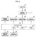
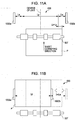
- FIG. 3 is a control block diagram of the entire photocopier including the finisher 500.
- reference numeral 150 denotes a CPU circuit part.
- This CPU circuit part 150 includes a CPU 150A, a ROM 151, and a RAM 152 and controls blocks 101, 201, 202, 209, 301, 401, and 501 according to the control program stored in the ROM 151.
- the RAM 152 temporarily stores the control data and is used as a work area for arithmetic processing necessary for the control.
- the document feeder control part 101 drives and controls the document feeder 100 on the basis of the instructions from the CPU circuit part 150.
- the image reader control part 201 drives and controls the scanner unit 104, the image sensor 109, and other components of the scanner 200, and sends an analog image signal received from the image sensor 109 to the image signal control part 202.
- the image signal control part 202 converts the analog image signal received from the image sensor 109 into a digital signal. Next, the image signal control part 202 performs various processes so as to convert this digital signal into a video signal and then sends the video signal to the printer control part 301. In addition, when the image signal control part 202 receives a digital image signal from an external computer 210 through an external interface 209, the image signal control part 202 performs various processes so as to convert this digital image signal into a video signal and then sends the video signal to the printer control part 301. The processing operation of the image signal control part 202 is controlled by the CPU circuit part 150.
- the printer control part 301 drives the exposure control part 110 on the basis of the video signal received from the image signal control part 202.
- the operation display control part 401 performs information exchange between the operation display 400 shown in FIG. 1 and the CPU circuit part 150.
- the operation display control part 401 receives key signals corresponding to key operation from the operation display 400 and sends the key signals to the CPU circuit part 150.
- the operation display control part 401 receives signals from the CPU circuit part 150 and displays the corresponding information on the screen of the operation display 400.
- the finisher control part 501 is provided, for example, in the finisher 500 and drives and controls the entire finisher by exchanging information with the CPU circuit part 150.
- the finisher control part 501 may be provided in the photocopier body 10.
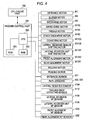
- FIG. 4 is a control block diagram of the finisher control part 501.
- the finisher control part 501 includes a CPU 550, a ROM 551, and a RAM 552.
- the finisher control part 501 communicates with the CPU circuit part 150 in the photocopier body 10 via a communication IC (not shown) so as to exchange information.
- the finisher control part 501 executes various programs stored in the ROM 551 so as to drive and control the finisher 500.
- FIG. 5 is a schematic view showing the structure of the lateral register correction unit 1001. Conveying a sheet in the sheet conveying direction, the lateral register correction unit 1001 shifts the sheet in the direction perpendicular to the sheet conveying direction (hereinafter referred to as "width direction").
- reference numeral M1103 denotes a conveying motor.
- the conveying motor M1103 drives the conveying rollers 1101a and 1102a via timing belts 1115 and 1116.
- the conveying rollers 1101a and 1102a convey sheets together with the driven rollers 1101b and 1102b.
- Reference numeral 1104 denotes a lateral register sensor.
- the lateral register sensor 1104 is a position detecting device that detects the position of the edge of a sheet being conveyed.
- the lateral register sensor 1104 is mounted in a lateral register sensor unit 1105.
- the lateral register sensor unit 1105 is moved from side to side as shown by arrow 1300 by a lateral register sensor shifting motor M1106.
- the home position of the lateral register sensor unit 1105 is detected by a lateral register HP-sensor 1108.
- the lateral register correction unit 1001 is not integral with the lateral register sensor unit 1105.
- Reference numeral M1107 denotes a lateral register correction unit shifting motor, which moves the lateral register correction unit 1001 from side to side as shown by arrow 1301.
- the home position of the lateral register correction unit 1001 is detected by a lateral register correction unit HP sensor 1109.
- Reference numeral 1112 denotes a trailing edge detecting sensor.
- the trailing edge detecting sensor 1112 detects an incoming sheet and detects that the trailing edge of the sheet has passed between the conveying rollers 1101a and 1101b in the lateral register correction unit 1001.
- the lateral register sensor shifting motor M1106 is activated.
- the lateral register sensor unit 1105 is thereby moved leftward as shown by the arrow from the home position to a standby position that is predetermined on the basis of the sheet size and the offset distance.
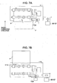
- the lateral register correction unit shifting motor M1107 is activated and starts to move the lateral register correction unit 1001 to the left as shown by the arrow in FIG. 7A .
- the sheet P thereby starts to be moved to the left, being conveyed.
- the side edge of the sheet P passes over the lateral register sensor 1104, and the lateral register sensor 1104 thereby stops detecting the sheet P.
- the lateral register correction unit shifting motor M1107 is stopped. By this operation, the lateral register of the sheet P is corrected, and the sheet P is shifted to a predetermined position shown by reference letter P'.
- the lateral register correction unit shifting motor M1107 moves the lateral register correction unit 1001 to the right as shown by the arrow in FIG. 7B so as to return the lateral register correction unit 1001 to the home position shown in FIGS. 6A and 6B .
- the lateral register sensor shifting motor M1106 is activated.
- the lateral register sensor unit 1105 is thereby moved leftward as shown by the arrow from the home position to a standby position that is predetermined on the basis of the sheet size and the offset distance.
- the lateral register correction unit shifting motor M1107 is activated and starts to move the lateral register correction unit 1001 to the right as shown by the arrow in FIG. 9A .
- the sheet P thereby starts to be moved to the right, being conveyed. Soon afterward, the side edge of the sheet P is detected by the lateral register sensor 1104.
- the lateral register correction unit shifting motor M1107 is stopped. By this operation, the lateral register of the sheet P is corrected, and the sheet P is shifted to a predetermined position shown by reference letter P'.
- the lateral register correction unit shifting motor M1107 moves the lateral register correction unit 1001 to the left as shown by the arrow in FIG. 9B so as to return the lateral register correction unit 1001 to the home position shown in FIGS. 8A and 8B .
- the sheet is conveyed to the process tray 630 of the finisher 500.
- alignment operation is performed.
- FIG. 10 shows the configuration of the process tray 630 and aligning plates that align the sheets stacked on the process tray 630.
- reference numeral M3 denotes a discharge motor. Being driven by this discharge motor M3, the conveying roller pair 507 discharges the sheets onto the process tray 630.
- Reference numerals M1202 and M1201 denote a front alignment motor and a rear alignment motor, respectively.
- the front alignment motor M1202 and the rear alignment motor M1201 drive a front aligning plate 1002a and a rear aligning plate 1002b, respectively.
- the front aligning plate 1002a and the rear aligning plate 1002b constitute a pair of aligning plates and are independently driven in the direction shown by arrows 1400 and 1401 so as to align the sheets.
- Reference numerals 1203 and 1202 denote a front alignment HP sensor and a rear alignment HP sensor, respectively.
- the front alignment HP sensor 1203 and the rear alignment HP sensor 1202 detect the home positions of the front aligning plate 1002a and the rear aligning plate 1002b, respectively.
- a sheet stack P conveyed onto the process tray 630 is shifted by a stack offset distance La and aligned before the sheet stack P is discharged onto the discharge tray 700.
- the front aligning plate 1002a and the rear aligning plate 1002b first stand by at their respective standby positions.
- the standby positions are at equal distances from the center of the unit.
- the distance between the standby positions is the sum of the sheet width Lp and twice the stack offset distance La.
- the stack offset distance La is set so as to be larger than the sum of the distances of these lateral register displacements. That is to say, La>Lb+Lc.
- the front aligning plate 1002a remains at the standby position and functions as a standard.
- the rear aligning plate 1002b reciprocates a distance approximately twice as long as the offset distance La. The sheet stack P is thereby pressed against the front aligning plate 1002a so as to be aligned (one side standard).
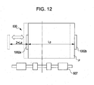
- the rear aligning plate 1002b When another sheet stack P is offset backward by La and aligned, as shown in FIG. 12 , the rear aligning plate 1002b remains at the standby position and functions as a standard. After the sheet stack P has entered the process tray 630, the front aligning plate 1002a reciprocates a distance approximately twice as long as the offset distance La.. The sheet stack P is thereby pressed against the rear aligning plate 1002b so as to be aligned (one side standard).
- FIG. 13A shows first standby positions of the aligning plates 1002a and 1002b in the case where a sheet stack is offset forward and aligned.
- the lateral register displacement Lb that occurs in the photocopier body 10 has been corrected by the operation of the lateral register correction unit 1001.
- the sheet stack P has been shifted by the stack offset distance La by the operation of the lateral register correction unit 1001.
- the sheet stack P is loaded at the front loading position (first loading position) shown in FIGS. 13A and 13B .
- the alignment distance Ld of each of the aligning plates 1002a and 1002b is set slightly larger than the distance Le of the displacement that occurs in the conveying path from the lateral register correction unit 1001 to the process tray 630 in the finisher 500 (Ld > Le). Therefore, the sheet stack P does not collide with the aligning plate 1002a or 1002b at the standby position to cause conveyance failure.
- the front aligning plate 1002a and the rear aligning plate 1002b are each reciprocated by the alignment distance Ld so as to align the sheet stack P (center alignment). That is to say, the aligning plates 1002a and 1002b align the sheet stack loaded on the process tray 630 from the first standby positions corresponding to the front loading position.
- the aligned sheet stack is discharged onto the stack tray 700 by the discharge rollers 680a and 680b.
- the alignment by the aligning plates 1002a and 1002b is performed every time a sheet stack is discharged onto the process tray 630.
- a similar alignment operation is performed in the case where a sheet stack is offset backward and aligned.
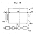
- the center of offset is behind the center of the unit. That is to say, being offset by the lateral register correction unit 1001, the sheet stack is loaded at a rear loading position (second loading position) shown in FIG. 14 .
- the positions of the aligning plates 1002a and 1002b shown by dashed lines are second standby positions.
- the rear (second) loading position shown in FIG. 14 is a predetermined offset distance away from the front (first) loading position shown in FIGS. 13A and 13B .
- the aligning plates 1002a and 1002b stand by at their respective second standby positions corresponding to the rear (second) loading position ( FIG. 14 ).
- the aligning plates 1002a and 1002b align the sheet stack loaded on the process tray 630 from the second standby positions corresponding to the rear (second) loading position.
- the alignment distance is the same as that in the case of forward offset shown in FIGS. 13A and 13B . Therefore, the description thereof will be omitted.
- the aligned sheet stack is discharged onto the stack tray 700 by the discharge rollers 680a and 680b.
- a sheet stack is aligned at the front (first) loading position shown in FIGS. 13A and 13B and then discharged onto the stack tray 700.
- another sheet stack is aligned at the rear (second) loading position shown in FIG. 14 and then discharged onto the stack tray 700.
- the front alignment motor M1202 and the rear alignment motor M1201 are stepping motors and self-activated.
- a sheet stack P is loaded on the process tray 630, being shifted to a predetermined offset position.
- Each sheet constituting the sheet stack is shifted by the lateral register correction unit 1001.
- the aligning plates 1002a and 1002b are moved to positions corresponding to the sheet offset position in advance.
- the aligning plates 1002a and 1002b are moved to positions corresponding to the front loading position in advance.
- the aligning plates 1002a and 1002b are moved to positions corresponding to the rear loading position in advance.
- the distance between the aligning plates 1002a and 1002b is smaller than that in the case where the sheets are not shifted, the time of alignment operation can be reduced, and high productivity can be achieved.
- the alignment distance Ld is set slightly larger than the distance Le of the lateral register displacement that occurs in the conveying path from the lateral register correction unit 1001 to the process tray 630 in the finisher 500.
- the offset distance La has needed to be set larger than the sum of the distance Lb of the lateral register displacement in the photocopier body 10 and the distance Lc of the lateral register displacement in the finisher 500.
- the offset distance can be set more flexibly. Therefore, a more user-friendly and more productive finisher 500 and an image forming apparatus having the same can be provided.
- the offset distance is set smaller than that in the case of large sized sheets.
- a larger number of sheet stacks can be stacked in a well-aligned state.
- the maximum,number of sheet stacks that can be loaded on the stack tray 700 is increased.
- the stacked sheet stacks do not collapse easily.
- a larger number of copies can be set for a job.
- system downtime due to collapse of sheet stacks is reduced. Therefore, the productivity can be further improved.
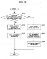
- the function of lateral register correction can be cut off. That is to say, there is a mode in which, if there is a malfunction in the lateral register correction unit 1001, the finisher 500 operates without activating the lateral register correction unit 1001.
- the mode in which the finisher 500 operates without activating the lateral register correction unit 1001 will hereinafter be referred to as "redundant mode.”
- the CPU 550 When the finisher 500 is powered on, the initial operation of the motors is performed for checking the operation of the loads.
- the CPU 550 outputs a drive signal of the lateral register correction unit shifting motor M1107 so as to move the lateral register correction unit 1001.
- the lateral register correction unit HP sensor 1109 functions as a malfunction detecting device.
- the CPU 550 then monitors whether there is a change in the signal of the lateral register correction unit HP sensor 1109 to detect a malfunction in the lateral register correction unit 1001 (S101).
- the CPU 550 determines that the lateral register correction unit 1001 is normal. If the CPU 550 determines that the lateral register correction unit 1001 is ormal (in the case of "NO" in S101), the CPU 550 sets the alignment operation to a first process including the lateral register correction (S102). Next, a first alignment operation including the lateral register correction is performed (S103).
- the CPU 550 determines that there is a malfunction in the lateral register correction unit 1001. In this case (in the case of "YES" in S101), the CPU 550 enters the redundant mode.
- the CPU 550 shuts down the lateral register correction unit shifting motor M1107 and the lateral register sensor shifting motor M1106 (S104).
- the CPU 550 sets the alignment operation to a second process in which the lateral register correction is not performed (S105).
- the second alignment operation is the same as the operation in the case where the lateral register correction is not performed by the lateral register correction unit 1001 shown in FIGS. 11A, 11B , and 12 .
- the CPU 550 is switched to the redundant mode, in which the function of lateral register correction is cut off and normal operation is continued. Therefore, system downtime can be avoided. Therefore, high productivity can be achieved.
- sheet stacks are discharged without being offset.
- the lateral register correction unit 1001 when the lateral register correction unit 1001 performs the lateral register correction, the lateral register sensor unit 1105 is moved from the home position to a standby position that is predetermined on the basis of the sheet size and the offset distance (see FIGS. 6A, 6B , 8A, and 8B ).
- the lateral register sensor unit 1105 is moved from the home position to a standby position that is predetermined on the basis of the sheet size only.
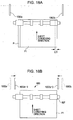
- the front aligning plate 1002a and the rear aligning plate 1002b move from their respective initial positions shown in FIG. 16A to their respective standby positions and stand by there.
- These standby positions are determined taking into consideration the distance of lateral register displacement that occurs in the photocopier body 10 and the distance of lateral register displacement that occurs in the finisher 500.
- These standby positions are positions such that the alignment operation is possible even if a sheet stack P2 is displaced from the ideally corrected position by a maximum distance L22.
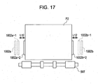
- the front aligning plate 1002a and the rear aligning plate 1002b move to their respective standby positions 1002a-1 and 100-2b-1 according to the sheet size.
- the front aligning plate 1002a and the rear aligning plate 1002b each reciprocate a distance L12 between the standby positions 1002a-1 and 1002b-1 and pressing positions 1002a-2 and 1002b-2 so as to align the sheet stack P2. This alignment is performed every time a sheet stack is loaded on the process tray 630.
- the lateral register displacement of a sheet stack P1 is corrected by the lateral register correction unit 1001 in the finisher 500. Therefore, it is only necessary to take into consideration the lateral register displacement that occurs in the sheet conveyance from the lateral register correction unit 1001 to the process tray 630. Therefore, the distance L21 of displacement of the sheet stack P1 to be taken into consideration, that is to say, the distance of displacement from the ideally corrected sheet stack P is smaller than the distance L22 shown in FIG. 16A .
- the front aligning plate 1002a and the rear aligning plate1002b each reciprocate a distance L11 between the standby positions 1002a-3 and 1002b-3 and pressing positions 1002a-2 and 1002b-2 so as to align the sheet stack P1. This alignment is performed every time a sheet stack is loaded on the process tray 630.
- the distance L12 is set larger than the distance L11. That is to say, the distance between the front aligning plate 1002a and the rear aligning plate 1002b in the case where the lateral register correction unit 1001 shifts.the sheets in the width direction so as to perform position correction in the width direction (the distance between the standby positions 1002a-3 and 1002b-3) is smaller than the distance between the front aligning plate 1002a and the rear aligning plate 1002b in the case where the lateral register correction unit 1001 does not shift the sheets (the distance between the standby positions 1002a-1 and 1002b-1).
- the reason that the standby positions of the front aligning plate 1002a and the rear aligning plate 1002b are set as above is that the distance of displacement to be taken in consideration in the process tray 630 in the case where the lateral register correction unit 1001 shifts the sheets in the width direction so as to perform position correction in the width direction is smaller than that in the case where the lateral register correction unit 1001 does not shift the sheets.
- the front alignment motor M1202 and the rear alignment motor M1201 are stepping motors and self-activated.
- the distance between the aligning plates 1002a and 1002b is smaller than that in the case where the sheets are not shifted, the time of alignment operation can be reduced, and high productivity can be achieved.
- the CPU 550 monitors whether there is a change in the signal of the lateral register correction unit HP sensor 1109 (malfunction detecting device). If the CPU 550 determines that there is a malfunction in the lateral register correction unit 1001, the lateral register correction unit 1001 does not perform the lateral register correction.
- a plurality of sheets are wrapped around the buffer roller 505.
- the wrapped sheets are then together discharged onto the process tray 630.
- sheets that are shifted by a shift conveying unit may be discharged one by one onto the process tray 630 so as to form a stack.
Landscapes
- Engineering & Computer Science (AREA)
- Mechanical Engineering (AREA)
- Pile Receivers (AREA)
Claims (5)
- Bogenverarbeitungsvorrichtung, umfassend:eine Verschiebungstransporteinheit (1001), ausgebildet zum Transportieren eines Bogens in einer Bogentransportrichtung und zum Verschieben des Bogens in einer zur Bogentransportrichtung senkrechten Breitenrichtung;eine Bogenverarbeitungsablage (630), ausgebildet zum Aufnehmen von Bögen von der Verschiebungstransporteinheit (1001),wobei die Verschiebungstransporteinheit (1001) ausgebildet ist zum Verschieben von Bögen in Breitenrichtung zu einer ersten Ablegeposition auf der Bogenverarbeitungsablage (630) und zu einer zur ersten Ablegeposition in Breitenrichtung versetzten weiteren Ablegeposition auf der Bogenverarbeitungsablage (630); undAusrichtelemente (1002a, 1002b), die in Breitenrichtung beweglich sind und den auf der Bogenverarbeitungsablage abgelegten Bogenstapel andrücken, um ihn in Breitenrichtung auszurichten;dadurch gekennzeichnet, dass die Ausrichtelemente (1002a, 1002b) derart ausgebildet sind, dass:falls die Bögen an der ersten Ablegeposition abgelegt sind, das Ausrichtelement vorab entsprechend der ersten Ablegeposition zu einer ersten Bereitschaftsposition bewegt wird und sich dann von der ersten Bereitschaftsposition bewegt, um den an der ersten Ablegeposition abgelegten Bogenstapel auszurichten; undfalls die Bögen an der weiteren Ablegeposition abgelegt sind, das Ausrichtelement vorab entsprechend der weiteren Ablegeposition zu einer weiteren Bereitschaftsposition bewegt wird und sich dann von der weiteren Bereitschaftsposition bewegt, um den an der weiteren Ablegeposition abgelegten Bogenstapel auszurichten.
- Bogenverarbeitungsvorrichtung nach Anspruch 1, wobei die Verschiebungstransporteinheit eine Positionsnachweiseinrichtung (1104, 1112) enthält, die die Kantenposition eines zu verschiebenden Bogens nachweist und der Verschiebungsabstand des Bogens gemäß der durch die Positionsnachweiseinrichtung nachgewiesenen Kantenposition des Bogens gesteuert wird.
- Bogenverarbeitungsvorrichtung nach Anspruch 1 oder 2, ferner umfassend eine Fehlfunktionsnachweiseinrichtung, die nachweist, ob eine Fehlfunktion in der Verschiebungstransporteinheit vorliegt,wobei, wenn die Fehlfunktionsnachweiseinrichtung eine Fehlfunktion in der Verschiebungstransporteinheit nachweist, die Bogenverarbeitungsvorrichtung betrieben wird, ohne die Verschiebungstransporteinheit zu aktivieren und der Abstand zwischen den Ausrichtelementen in ihren Bereitschaftspositionen auf einen Abstand A eingestellt ist, wobei gilt: A=Lp+2*Lawobei Lp die Bogenbreite und La der Stapelversetzungsabstand ist.
- Bogenverarbeitungsvorrichtung nach einem der vorhergehenden Ansprüche, wobei der Verschiebungsabstand des Bogens entsprechend der Bogengröße eingestellt werden kann.
- Bogenverarbeitungsvorrichtung nach einem der vorhergehenden Ansprüche, wobei sich das Ausrichtelement zum Ausrichten von Bögen jedes Mal bewegt, wenn Bögen an die Bogenverarbeitungsablage abgelegt werden.
Applications Claiming Priority (1)
| Application Number | Priority Date | Filing Date | Title |
|---|---|---|---|
| JP2005266112A JP4307429B2 (ja) | 2005-09-13 | 2005-09-13 | シート処理装置及び画像形成装置 |
Publications (3)
| Publication Number | Publication Date |
|---|---|
| EP1762522A2 EP1762522A2 (de) | 2007-03-14 |
| EP1762522A3 EP1762522A3 (de) | 2010-12-08 |
| EP1762522B1 true EP1762522B1 (de) | 2016-11-16 |
Family
ID=37526970
Family Applications (1)
| Application Number | Title | Priority Date | Filing Date |
|---|---|---|---|
| EP06120485.5A Active EP1762522B1 (de) | 2005-09-13 | 2006-09-12 | Bogenverarbeitungsgerät |
Country Status (3)
| Country | Link |
|---|---|
| US (3) | US7581725B2 (de) |
| EP (1) | EP1762522B1 (de) |
| JP (1) | JP4307429B2 (de) |
Families Citing this family (24)
| Publication number | Priority date | Publication date | Assignee | Title |
|---|---|---|---|---|
| JP4785474B2 (ja) * | 2005-09-13 | 2011-10-05 | キヤノン株式会社 | シート処理装置、および画像形成装置 |
| JP4819636B2 (ja) * | 2005-12-01 | 2011-11-24 | キヤノン株式会社 | シート処理装置と画像形成装置 |
| US7747212B2 (en) * | 2007-02-01 | 2010-06-29 | Toshiba Tec Kabushiki Kaisha | Sheet processing apparatus and sheet processing method |
| US7896333B2 (en) * | 2007-06-19 | 2011-03-01 | Kabushiki Kaisha Toshiba | Sheet processing apparatus |
| JP2009113924A (ja) * | 2007-11-07 | 2009-05-28 | Canon Inc | シート排出装置、シート処理装置、画像形成装置 |
| JP5247140B2 (ja) * | 2007-12-26 | 2013-07-24 | キヤノン株式会社 | シート搬送装置及びその制御方法 |
| US8308154B2 (en) * | 2008-02-25 | 2012-11-13 | Canon Kabushiki Kaisha | Image forming apparatus, image forming system, and control method therefor |
| JP5267231B2 (ja) * | 2009-03-11 | 2013-08-21 | コニカミノルタビジネステクノロジーズ株式会社 | 穿孔装置、後処理装置及び画像形成システム |
| JP5578830B2 (ja) * | 2009-10-21 | 2014-08-27 | キヤノン株式会社 | シート処理装置、画像形成装置及び画像形成システムの制御方法 |
| JP5578933B2 (ja) * | 2010-05-18 | 2014-08-27 | キヤノン株式会社 | シート処理装置及び画像形成システム |
| JP5047339B2 (ja) * | 2010-07-23 | 2012-10-10 | シャープ株式会社 | 画像形成装置 |
| JP5972095B2 (ja) * | 2011-08-08 | 2016-08-17 | キヤノン株式会社 | シート処理装置及びその制御方法 |
| JP6128829B2 (ja) * | 2012-01-10 | 2017-05-17 | キヤノン株式会社 | 後処理装置及びその制御方法 |
| JP5997495B2 (ja) * | 2012-05-01 | 2016-09-28 | キヤノン株式会社 | シート搬送装置およびそれを備えた画像形成システム |
| JP5966614B2 (ja) * | 2012-05-25 | 2016-08-10 | 富士ゼロックス株式会社 | シート処理装置、画像形成システム |
| JP6037303B2 (ja) * | 2012-06-29 | 2016-12-07 | ニスカ株式会社 | シート整合装置及びこれを備えた画像形成システム |
| JP6167510B2 (ja) | 2012-12-03 | 2017-07-26 | 株式会社リコー | 後処理装置、画像形成装置及び画像形成システム |
| EP3068977B1 (de) | 2013-11-14 | 2019-07-10 | United Technologies Corporation | Gasturbinen-leitschaufelanordnung welche rotierende leitschaufeln mit erhebungen auf der druck- oder saugseite beinhaltet |
| JP6292873B2 (ja) * | 2013-12-27 | 2018-03-14 | キヤノン株式会社 | シート処理装置及び画像形成システム |
| US10562731B2 (en) * | 2016-12-09 | 2020-02-18 | Canon Finetech Nisca Inc. | Apparatus for processing sheets and apparatus for forming images provided with the apparatus |
| US10604369B2 (en) * | 2016-12-09 | 2020-03-31 | Canon Finetech Nisca Inc. | Apparatus for processing sheets and apparatus for forming images provided with the apparatus |
| DE102019129788A1 (de) * | 2019-11-05 | 2021-05-06 | Aixtron Se | Verwendung eines CVD Reaktors zum Abscheiden zweidimensionaler Schichten |
| WO2022044535A1 (ja) * | 2020-08-26 | 2022-03-03 | 京セラドキュメントソリューションズ株式会社 | シート搬送装置、画像形成装置 |
| JP2024152139A (ja) * | 2023-04-14 | 2024-10-25 | 京セラドキュメントソリューションズ株式会社 | シート搬送装置、画像形成装置、動作制御方法 |
Family Cites Families (16)
| Publication number | Priority date | Publication date | Assignee | Title |
|---|---|---|---|---|
| JPS6178163A (ja) | 1984-09-26 | 1986-04-21 | Hitachi Ltd | 半導体装置の製造方法 |
| US5263697A (en) * | 1989-04-18 | 1993-11-23 | Ricoh Company, Ltd. | Finisher for an image forming apparatus |
| US5219159A (en) * | 1992-06-01 | 1993-06-15 | Xerox Corporation | Translating nip registration device |
| US6059285A (en) * | 1996-12-18 | 2000-05-09 | Canon Kabushiki Kaisha | Sheet conveying apparatus |
| JP3636858B2 (ja) * | 1997-03-12 | 2005-04-06 | コニカミノルタビジネステクノロジーズ株式会社 | フィニッシャ |
| JP4154088B2 (ja) * | 1999-08-05 | 2008-09-24 | グラドコ株式会社 | シート後処理装置 |
| JP2001261196A (ja) * | 2000-03-15 | 2001-09-26 | Fuji Photo Film Co Ltd | シート材位置決め方法及び装置 |
| JP3973836B2 (ja) * | 2000-12-15 | 2007-09-12 | 株式会社リコー | シート状媒体処理装置、画像形成装置、シート状媒体後処理装置 |
| JP4188572B2 (ja) | 2001-03-30 | 2008-11-26 | 株式会社リコー | シート状媒体整合装置 |
| US6832759B2 (en) | 2001-03-30 | 2004-12-21 | Ricoh Company, Ltd. | Sheet-shaped medium aligning apparatus, image forming apparatus, and sheet-shaped medium after-treatment apparatus |
| JP3793444B2 (ja) * | 2001-10-26 | 2006-07-05 | 株式会社リコー | 用紙処理装置および画像形成装置 |
| JP2005219909A (ja) | 2004-02-09 | 2005-08-18 | Canon Finetech Inc | シート積載装置及びこれを備えた画像形成装置 |
| JP2005306505A (ja) * | 2004-04-16 | 2005-11-04 | Canon Finetech Inc | シート処理装置及びこれを備えた画像形成装置 |
| JP2006206281A (ja) * | 2005-01-31 | 2006-08-10 | Canon Inc | 画像形成装置 |
| JP4819636B2 (ja) * | 2005-12-01 | 2011-11-24 | キヤノン株式会社 | シート処理装置と画像形成装置 |
| US8047537B2 (en) * | 2009-07-21 | 2011-11-01 | Xerox Company | Extended registration control of a sheet in a media handling assembly |
-
2005
- 2005-09-13 JP JP2005266112A patent/JP4307429B2/ja not_active Expired - Fee Related
-
2006
- 2006-09-11 US US11/530,792 patent/US7581725B2/en not_active Expired - Fee Related
- 2006-09-12 EP EP06120485.5A patent/EP1762522B1/de active Active
-
2009
- 2009-07-20 US US12/506,050 patent/US7866652B2/en not_active Ceased
-
2016
- 2016-03-16 US US15/072,221 patent/USRE46875E1/en active Active
Non-Patent Citations (1)
| Title |
|---|
| None * |
Also Published As
| Publication number | Publication date |
|---|---|
| EP1762522A2 (de) | 2007-03-14 |
| JP4307429B2 (ja) | 2009-08-05 |
| US7866652B2 (en) | 2011-01-11 |
| JP2007076800A (ja) | 2007-03-29 |
| USRE46875E1 (en) | 2018-05-29 |
| US20070075482A1 (en) | 2007-04-05 |
| US7581725B2 (en) | 2009-09-01 |
| US20090283957A1 (en) | 2009-11-19 |
| EP1762522A3 (de) | 2010-12-08 |
Similar Documents
| Publication | Publication Date | Title |
|---|---|---|
| USRE46875E1 (en) | Sheet processing apparatus | |
| US7802782B2 (en) | Sheet processing apparatus and image forming system | |
| US8292285B2 (en) | Sheet processing apparatus, image forming apparatus and sheet buffering device that maintain alignment of sheets of sheet bundle | |
| US8736859B2 (en) | Image forming system and printer controller | |
| US7017903B2 (en) | Sheet conveying apparatus | |
| EP2829497B1 (de) | Faltvorrichtung, nachbearbeitungsvorrichtung sowie bilderzeugungsvorrichtung | |
| US20060261543A1 (en) | Sheet stacking apparatus and image forming apparatus | |
| JP5218013B2 (ja) | 用紙載置ユニット、後処理装置、及び画像形成システム | |
| US7062214B2 (en) | Image forming apparatus with paper thickness detection unit for detecting overlap of regular and insertion sheets | |
| US7926800B2 (en) | Sheet processing apparatus and image forming apparatus | |
| US7841589B2 (en) | Image forming apparatus | |
| JP5578933B2 (ja) | シート処理装置及び画像形成システム | |
| JP4072386B2 (ja) | シート搬送装置および画像形成システム | |
| JP2025094673A (ja) | シート処理装置及び画像形成システム | |
| JP2003160272A (ja) | 画像形成装置 | |
| JP3880382B2 (ja) | 画像形成システム | |
| JP2004035228A (ja) | シート搬送装置および画像形成システム | |
| JP2004045464A (ja) | 画像形成装置および画像形成方法 | |
| JP2009202959A (ja) | 後処理装置及び画像形成システム |
Legal Events
| Date | Code | Title | Description |
|---|---|---|---|
| PUAI | Public reference made under article 153(3) epc to a published international application that has entered the european phase |
Free format text: ORIGINAL CODE: 0009012 |
|
| AK | Designated contracting states |
Kind code of ref document: A2 Designated state(s): AT BE BG CH CY CZ DE DK EE ES FI FR GB GR HU IE IS IT LI LT LU LV MC NL PL PT RO SE SI SK TR |
|
| AX | Request for extension of the european patent |
Extension state: AL BA HR MK YU |
|
| PUAL | Search report despatched |
Free format text: ORIGINAL CODE: 0009013 |
|
| AK | Designated contracting states |
Kind code of ref document: A3 Designated state(s): AT BE BG CH CY CZ DE DK EE ES FI FR GB GR HU IE IS IT LI LT LU LV MC NL PL PT RO SE SI SK TR |
|
| AX | Request for extension of the european patent |
Extension state: AL BA HR MK RS |
|
| 17P | Request for examination filed |
Effective date: 20110608 |
|
| AKX | Designation fees paid |
Designated state(s): DE FR GB IT |
|
| 17Q | First examination report despatched |
Effective date: 20150619 |
|
| RIC1 | Information provided on ipc code assigned before grant |
Ipc: B65H 9/10 20060101ALI20160428BHEP Ipc: B42C 1/12 20060101ALI20160428BHEP Ipc: B65H 29/12 20060101AFI20160428BHEP Ipc: B65H 31/34 20060101ALI20160428BHEP |
|
| GRAP | Despatch of communication of intention to grant a patent |
Free format text: ORIGINAL CODE: EPIDOSNIGR1 |
|
| INTG | Intention to grant announced |
Effective date: 20160610 |
|
| GRAS | Grant fee paid |
Free format text: ORIGINAL CODE: EPIDOSNIGR3 |
|
| GRAA | (expected) grant |
Free format text: ORIGINAL CODE: 0009210 |
|
| AK | Designated contracting states |
Kind code of ref document: B1 Designated state(s): DE FR GB IT |
|
| REG | Reference to a national code |
Ref country code: GB Ref legal event code: FG4D |
|
| REG | Reference to a national code |
Ref country code: FR Ref legal event code: PLFP Year of fee payment: 12 |
|
| REG | Reference to a national code |
Ref country code: DE Ref legal event code: R096 Ref document number: 602006050914 Country of ref document: DE |
|
| REG | Reference to a national code |
Ref country code: DE Ref legal event code: R096 Ref document number: 602006050914 Country of ref document: DE |
|
| REG | Reference to a national code |
Ref country code: DE Ref legal event code: R097 Ref document number: 602006050914 Country of ref document: DE |
|
| PLBE | No opposition filed within time limit |
Free format text: ORIGINAL CODE: 0009261 |
|
| STAA | Information on the status of an ep patent application or granted ep patent |
Free format text: STATUS: NO OPPOSITION FILED WITHIN TIME LIMIT |
|
| 26N | No opposition filed |
Effective date: 20170817 |
|
| REG | Reference to a national code |
Ref country code: FR Ref legal event code: PLFP Year of fee payment: 13 |
|
| PGFP | Annual fee paid to national office [announced via postgrant information from national office to epo] |
Ref country code: IT Payment date: 20190923 Year of fee payment: 14 |
|
| PG25 | Lapsed in a contracting state [announced via postgrant information from national office to epo] |
Ref country code: IT Free format text: LAPSE BECAUSE OF NON-PAYMENT OF DUE FEES Effective date: 20200912 |
|
| PGFP | Annual fee paid to national office [announced via postgrant information from national office to epo] |
Ref country code: FR Payment date: 20210819 Year of fee payment: 16 |
|
| PG25 | Lapsed in a contracting state [announced via postgrant information from national office to epo] |
Ref country code: FR Free format text: LAPSE BECAUSE OF NON-PAYMENT OF DUE FEES Effective date: 20220930 |
|
| PGFP | Annual fee paid to national office [announced via postgrant information from national office to epo] |
Ref country code: DE Payment date: 20240820 Year of fee payment: 19 |
|
| PGFP | Annual fee paid to national office [announced via postgrant information from national office to epo] |
Ref country code: GB Payment date: 20240820 Year of fee payment: 19 |