EP1758240A2 - Dispositif de commande de moteur - Google Patents
Dispositif de commande de moteur Download PDFInfo
- Publication number
- EP1758240A2 EP1758240A2 EP06119540A EP06119540A EP1758240A2 EP 1758240 A2 EP1758240 A2 EP 1758240A2 EP 06119540 A EP06119540 A EP 06119540A EP 06119540 A EP06119540 A EP 06119540A EP 1758240 A2 EP1758240 A2 EP 1758240A2
- Authority
- EP
- European Patent Office
- Prior art keywords
- axis
- motor
- current
- estimator
- value
- Prior art date
- Legal status (The legal status is an assumption and is not a legal conclusion. Google has not performed a legal analysis and makes no representation as to the accuracy of the status listed.)
- Granted
Links
Images


Classifications
-
- H—ELECTRICITY
- H02—GENERATION; CONVERSION OR DISTRIBUTION OF ELECTRIC POWER
- H02P—CONTROL OR REGULATION OF ELECTRIC MOTORS, ELECTRIC GENERATORS OR DYNAMO-ELECTRIC CONVERTERS; CONTROLLING TRANSFORMERS, REACTORS OR CHOKE COILS
- H02P21/00—Arrangements or methods for the control of electric machines by vector control, e.g. by control of field orientation
- H02P21/14—Estimation or adaptation of machine parameters, e.g. flux, current or voltage
- H02P21/18—Estimation of position or speed
-
- H—ELECTRICITY
- H02—GENERATION; CONVERSION OR DISTRIBUTION OF ELECTRIC POWER
- H02P—CONTROL OR REGULATION OF ELECTRIC MOTORS, ELECTRIC GENERATORS OR DYNAMO-ELECTRIC CONVERTERS; CONTROLLING TRANSFORMERS, REACTORS OR CHOKE COILS
- H02P2203/00—Indexing scheme relating to controlling arrangements characterised by the means for detecting the position of the rotor
- H02P2203/05—Determination of the rotor position by using two different methods and/or motor models
-
- H—ELECTRICITY
- H02—GENERATION; CONVERSION OR DISTRIBUTION OF ELECTRIC POWER
- H02P—CONTROL OR REGULATION OF ELECTRIC MOTORS, ELECTRIC GENERATORS OR DYNAMO-ELECTRIC CONVERTERS; CONTROLLING TRANSFORMERS, REACTORS OR CHOKE COILS
- H02P2203/00—Indexing scheme relating to controlling arrangements characterised by the means for detecting the position of the rotor
- H02P2203/09—Motor speed determination based on the current and/or voltage without using a tachogenerator or a physical encoder
-
- H—ELECTRICITY
- H02—GENERATION; CONVERSION OR DISTRIBUTION OF ELECTRIC POWER
- H02P—CONTROL OR REGULATION OF ELECTRIC MOTORS, ELECTRIC GENERATORS OR DYNAMO-ELECTRIC CONVERTERS; CONTROLLING TRANSFORMERS, REACTORS OR CHOKE COILS
- H02P2203/00—Indexing scheme relating to controlling arrangements characterised by the means for detecting the position of the rotor
- H02P2203/11—Determination or estimation of the rotor position or other motor parameters based on the analysis of high frequency signals
-
- H—ELECTRICITY
- H02—GENERATION; CONVERSION OR DISTRIBUTION OF ELECTRIC POWER
- H02P—CONTROL OR REGULATION OF ELECTRIC MOTORS, ELECTRIC GENERATORS OR DYNAMO-ELECTRIC CONVERTERS; CONTROLLING TRANSFORMERS, REACTORS OR CHOKE COILS
- H02P2207/00—Indexing scheme relating to controlling arrangements characterised by the type of motor
- H02P2207/05—Synchronous machines, e.g. with permanent magnets or DC excitation
Definitions
- the present invention relates to a motor control device for controlling an operation of a motor.
- the present invention also relates to a motor drive system including this motor control device.
- a motor control device without a rotor position sensor (a position sensor-less motor control device) is developed.
- This a motor control device estimates a rotor position in a motor without a rotor position sensor and controls the motor base on the estimated rotor position.
- Fig. 21 shows an example of a block diagram for a motor control device 103 of this type.
- an estimated axis for the control corresponding to a d-axis in a vector control of a motor is a ⁇ -axis
- an estimated axis for the control corresponding to a q-axis is a ⁇ -axis.
- FIG. 23 shows a relationship among the d-axis, the q-axis, the ⁇ -axis and the ⁇ -axis.
- the reference numeral E ex in Fig. 23 represents a voltage vector that is usually called an extension induction voltage (an extended electromotive force).
- a current detector 11 detects U-phase current i u and V-phase current i v of motor current supplied from a PWM inverter 2 to a motor 1 that is a salient pole machine.
- a coordinate converter 12 converts the U-phase current i u and the V-phase current i v into ⁇ -axis current i ⁇ and ⁇ -axis current i ⁇ .
- a position/speed estimator 120 (hereinafter referred to as "estimator 120" simply) estimates and outputs an estimated rotor position ⁇ e and an estimated motor speed ⁇ e .
- a subtracter 19 subtracts the estimated motor speed ⁇ e given by the estimator 120 from a specified motor speed value ⁇ * and outputs the result.
- a speed controller 17 generates a specified ⁇ -axis current value i ⁇ * to be followed by the ⁇ -axis current i ⁇ based on the subtraction result ( ⁇ * - ⁇ e ) from the subtracter 19.
- a magnetic flux controller 116 outputs a specified ⁇ -axis current value i ⁇ * to be followed by the ⁇ -axis current i ⁇ based on the specified ⁇ -axis current value i ⁇ * and the like.
- a current controller 15 outputs a specified ⁇ -axis voltage value v ⁇ * and a specified ⁇ -axis voltage value v ⁇ * so that both a current error (i ⁇ *-i ⁇ ) and a current error (i ⁇ *-i ⁇ ) given by the subtracters 13 and 14 converge to zero.
- a coordinate converter 18 performs inverse conversion of the specified ⁇ -axis voltage value v ⁇ * and the specified ⁇ -axis voltage value v ⁇ * based on the estimated rotor position ⁇ e given by the estimator 120 and generates specified three-phase voltage values including a specified U-phase voltage value v u *, a specified V-phase voltage value v v * and specified W-phase voltage value v w *, which are supplied to the PWM inverter 2.
- the PWM inverter 2 generates a signal modulated by pulse width based on the specified three-phase voltage values (v u *, v v * and v w *) and supplies the motor 1 with motor current corresponding to the specified three-phase voltage values for driving the motor 1.
- Fig. 22 shows an inside structure of the estimator 120.
- the estimator 120 includes an axial error estimator 130, a proportional-plus-integral calculator 131 and an integrator 132.
- the axial error estimator 130 estimates an axial error ⁇ between the d-axis and the ⁇ -axis.
- the axial error estimator 130 calculates the axial error ⁇ by using the equation (1) below, for example.
- L d and L q represent a d-axis inductance and a q-axis inductance of the motor 1, respectively, and R a represents motor resistance of the motor 1.
- s is the Laplace operator. There are proposed various methods for estimating a rotor position.
- a value of q-axis inductance of a motor is used as an operation parameter in a calculation equation for estimation as the equation (1) below.
- ⁇ ⁇ tan - 1 ⁇ - E ex ⁇
- E ex ⁇ tan - 1 ⁇ - v ⁇ * - R a + L d ⁇ s ⁇ i ⁇ + ⁇ e ⁇ L q ⁇ i ⁇ v ⁇ * - R a + L d ⁇ s ⁇ i ⁇ - ⁇ e ⁇ L q ⁇ i ⁇
- the above equation (1) is a calculation equation for calculating the axial error ⁇ described in Japanese patent No. 3411878 (hereinafter referred to as a first patent document).
- a difference between the d-axis and the ⁇ -axis (dc-axis) with reference to the d-axis is defined as ⁇ in the first patent document while a difference between the d-axis and the ⁇ -axis (dc-axis) with reference to the ⁇ -axis is defined as ⁇ , so the sign (negative or positive) is opposite between the calculation equation of the axial error ⁇ in the first patent document and the equation (1).
- E ex ⁇ and E ex ⁇ represent a ⁇ -axis component and a ⁇ -axis component of an extension induction voltage (an extended electromotive force) E ex , respectively.
- the proportional-plus-integral calculator 131 performs a proportional plus integral control in cooperation with each portion constituting the motor control device 103 for realizing a PLL (Phase Locked Loop), and it calculates the estimated motor speed ⁇ e so that the axial error ⁇ calculated by the axial error estimator 130 converges to zero.
- the integrator 132 integrates the estimated motor speed ⁇ e outputted by the proportional-plus-integral calculator 131 and calculates the estimated rotor position ⁇ e .
- the estimated motor speed ⁇ e outputted by the proportional-plus-integral calculator 131 and the estimated rotor position ⁇ e outputted by the integrator 132 are imparted as output values of the estimator 120 to each part of the motor control device 103 that needs the values.
- the motor control device 103 Since the motor control device 103 is structured as described above, the axial error ⁇ between the d-axis and the ⁇ -axis converges to zero so that a stable motor control can be realized. Note that if the axial error ⁇ is maintained at zero, the d-axis current i d follows the specified ⁇ -axis current value i ⁇ * while the q-axis current i q follows the specified ⁇ -axis current value i ⁇ *.
- the calculation equation for calculating the d-axis current i d for performing a maximum torque control utilizing a reluctance torque is known widely.
- the magnetic flux controller 116 calculates the specified ⁇ -axis current value i ⁇ * based on the equation (2) below.
- ⁇ a represents armature flux linkage of the permanent magnet.
- JP-A-2003-309992 (hereinafter referred to as a second patent document) discloses a position sensor-less control method, in which a phase of motor current is adjusted so that a value of motor current becomes a minimum value.
- JP-A-2003-219682 (hereinafter referred to as a fourth patent document)
- JP-A-2002-51597 (hereinafter referred to as a fifth patent document)
- JP-A-2003-153582 (hereinafter referred to as a sixth patent document) disclose motor control techniques utilizing injection of high frequency voltage or high frequency current.
- JP-A-H10-94298 discloses a technique concerning switching between a low speed sensor-less control and a high speed sensor-less control.
- the calculation equation for calculating the specified ⁇ -axis current value i ⁇ * for performing the maximum torque control or the like includes a plurality of motor parameters whose true values are not known. Therefore, if there are errors between the motor parameters (the operation parameters) that are used for calculating the specified ⁇ -axis current value i ⁇ * and true motor parameters, a desired motor control cannot be performed. For this reason, it is essential to perform an adjustment for decreasing the errors as much as possible. However, the adjustment for the plurality of motor parameters is not easy, and a lot of time is necessary for the adjustment.
- the parameter adjustment for the rotor position estimation and the parameter adjustment for calculating the specified ⁇ -axis current value i ⁇ * are performed independently, so more time for the adjustments is necessary.
- the error in the adjustment of the parameter for estimating the rotor position and the error in the adjustment of the parameter for calculating the specified ⁇ -axis current value i ⁇ * are affected by each other so that the adjustments become more difficult.
- optimization of the parameters also becomes difficult resulting in difficulty in realizing an optimal drive of the motor.
- the techniques described in the first patent document, the second patent document and the first non-patent document which are described above cannot solve the problem described above. Furthermore, the second patent document utilizes an approximation of ⁇ ⁇ 0, so estimation accuracy becomes lower as a value of ⁇ increases.
- An object of the present invention is to provide a motor control device that can contribute to facilitation of adjustment of an operation parameter for obtaining a maximum torque control or the like, and/or reduction of quantity of calculations. Furthermore, it is another object to provide a motor drive system having the motor control device.
- a first motor control device includes an estimator for estimating a rotor position of a motor having a salient pole by using a value corresponding to the q-axis inductance of the motor as an operation parameter, and a controller for controlling the motor based on the estimated rotor position, wherein the estimator generates a deviation between the d-axis and the ⁇ -axis by performing the estimation of the rotor position based on a value between a real q-axis inductance and a real d-axis inductance of the motor adopted as the operation parameter, where the d-axis is an axis parallel to a magnetic flux generated by a permanent magnet that constitutes the rotor, the ⁇ -axis is an estimated axis for the control corresponding to the d-axis, and the q-axis is an axis leading the d-axis by 90 degrees in electrical angle.
- the controller controls the motor so that a ⁇ -axis component of a motor current supplied to the motor is maintained to be a predetermined value of zero or close to zero.
- the estimator also estimates a rotation speed of the rotor corresponding to the estimation of the rotor position
- the controller includes a specified current calculator that generates a specified ⁇ -axis current value and a specified ⁇ -axis current value to be followed by the ⁇ -axis component and a ⁇ -axis component of the motor current so that the estimated rotation speed follows a specified motor speed value given externally, where the ⁇ -axis is an axis leading the ⁇ -axis by 90 degrees in electrical angle.
- the specified current calculator maintains the specified ⁇ -axis current value at the predetermined value regardless of a value of the specified ⁇ -axis current value, so that the ⁇ -axis component of the motor current is maintained at the predetermined value regardless of a value of the ⁇ -axis component of the motor current.
- a value of the operation parameter is set to a value such that the motor current becomes a minimum value in the state where the ⁇ -axis component of the motor current is the predetermined value and the motor is supplied with a predetermined load torque.
- a value of the operation parameter is set to a value such that a loss of the motor becomes a minimum value in the state where the ⁇ -axis component of the motor current is the predetermined value and the motor is under a predetermined load condition.
- the estimator performs the estimation of the rotor position by using a q-axis inductance L as the operation parameter that satisfies the following expression L d ⁇ L ⁇ (L d + L q )/2, where L q and L d are respectively the real q-axis inductance and the real d-axis inductance of the motor.
- the operation parameter may have a fixed value.
- a second motor control device controls the motor by decomposing a motor current that flows in the motor into a qm-axis component parallel to a qm-axis and a dm-axis component parallel to a dm-axis, where the qm-axis is a rotation axis having the same direction as a current vector for realizing a maximum torque control or a rotation axis leading said rotation axis in phase, and the dm-axis is a rotation axis that is orthogonal to the qm-axis.
- the second motor control device includes an estimator for estimating a rotor position of the motor and a controller for controlling the motor based on the estimated rotor position.
- the controller controls the motor so that a ⁇ -axis and a ⁇ -axis follow the dm-axis and the qm-axis, respectively, where the d-axis is an axis parallel to a magnetic flux generated by a permanent magnet that constitutes a rotor, the ⁇ -axis is an estimated axis for the control corresponding to the d-axis, and the ⁇ -axis is an axis leading the ⁇ -axis by 90 degrees in electrical angle.
- the controller controls the motor so that a ⁇ -axis component of the motor current is maintained to be a predetermined value of zero or close to zero.
- the estimator estimates the rotor position by using an axial error between the qm-axis and the ⁇ -axis.
- the estimator estimates the rotor position by using an induction voltage vector on the qm-axis in the case where a vector of an induction voltage on a q-axis generated in the motor is decomposed into the induction voltage vector on the qm-axis and an induction voltage vector on the dm-axis, where the q-axis is an axis leading the d-axis by 90 degrees in electrical angle.
- the estimator estimates the rotor position by using a ⁇ -axis component and a ⁇ -axis component of the induction voltage vector on the qm-axis or by using the ⁇ -axis component of the induction voltage vector on the qm-axis.
- the estimator estimates the rotor position by using a flux linkage vector on the dm-axis in the case where a vector of a flux linkage on the d-axis of the motor is decomposed into a flux linkage vector on the qm-axis and the flux linkage vector on the dm-axis.
- the estimator estimates the rotor position by using a ⁇ -axis component and a ⁇ -axis component of the flux linkage vector on the dm-axis or by using the ⁇ -axis component of the flux linkage vector on the dm-axis.
- the controller includes a coordinate converter for converting a predetermined fixed axis component of the motor current into a ⁇ -axis component and a ⁇ -axis component by using the rotor position estimated by the estimator, the estimator estimates a dm-axis component and a qm-axis component of the motor current based on the ⁇ -axis component and the ⁇ -axis component of the motor current obtained by the coordinate converter, the rotor position is estimated by using an error current between the dm-axis component of the motor current obtained by the estimation and the ⁇ -axis component of the motor current obtained by the coordinate converter and also using an error current between the qm-axis component of the motor current obtained by the estimation and the ⁇ -axis component of the motor current obtained by the coordinate converter.
- the second motor control device further includes a superposer for adding a superposed voltage to a drive voltage for driving the motor, the superposed voltage having a frequency different from the drive voltage.
- the estimator is capable of performing a first estimation process for estimating the rotor position based on a superposed current that flows in the motor corresponding to the superposed voltage.
- the estimator is further capable of performing a second estimation process for estimating the rotor position based on a drive current corresponding to the drive voltage included in the motor current, and a estimation process that is performed actually is switched between the first estimation process and the second estimation process in accordance with speed information indicating a rotation speed of the rotor.
- the estimator includes a first candidate axial error calculator for calculating an axial error between the qm-axis and the ⁇ -axis as a first candidate axial error based on the superposed current, and a second candidate axial error calculator for calculating an axial error between the qm-axis and the ⁇ -axis as a second candidate axial error based on the drive current.
- the estimator switches information that is used for estimating the rotor position between the first candidate axial error and the second candidate axial error in accordance with the speed information, so as to switch between the first estimation process and the second estimation process.
- the estimator includes a first candidate speed calculator for calculating a rotation speed of the rotor as a first candidate speed based on the superposed current, and a second candidate speed calculator for calculating a rotation speed of the rotor as a second candidate speed based on the drive current, and it switches information that is used for estimating the rotor position between the first candidate speed and the second candidate speed in accordance with the speed information so as to switch between the first estimation process and the second estimation process.
- the estimator includes a first candidate position calculator for calculating a first candidate position as a candidate of the rotor position to be estimated based on the superposed current, and a second candidate position calculator for calculating a second candidate position as a candidate of the rotor position to be estimated based on the drive current, and it switches information that is used for estimating the rotor position between the first candidate position and the second candidate position based on the speed information so as to switch between the first estimation process and the second estimation process.
- the estimator switches the estimation process that is performed actually from one of the first and the second estimation processes to the other via an estimation process in which the estimation results of both the estimation processes are considered in accordance with the speed information or an elapsed time from a start of the switching.
- a voltage vector locus of the superposed voltage on a rotating coordinate axes describes a figure symmetric about the d-axis.
- the estimator estimates the rotor position in the first estimation process, it estimates the rotor position by using at least one-axis component of orthogonal two-axes components forming a vector of the superposed current.
- the estimator includes a coordinate rotator that performs a coordinate rotation of a vector of the superposed current by a phase difference between the dm-axis and the d-axis, and when it estimates the rotor position in the first estimation process, it estimates an axial error between the qm-axis and the ⁇ -axis by using at least one-axis component of orthogonal two-axes components forming a current vector obtained by the coordinate rotation and then estimates the rotor position by using the axial error.
- a motor drive system includes a motor, an inverter for driving the motor, and a motor control device having any structure described above, which controls the motor by controlling the inverter.
- Fig. 1 is a block diagram showing a general structure of a motor drive system according to a first embodiment of the present invention.
- Fig. 2 is an analytic model diagram of a motor according to the first embodiment of the present invention.
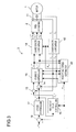
- Fig. 3 is a block diagram showing a structure of the motor drive system shown in Fig. 1.
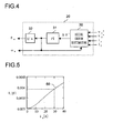
- Fig. 4 is a block diagram showing an inside structure of a position/speed estimator shown in Fig. 3.
- Fig. 5 is a graph showing a relationship between a q-axis inductance as an operation parameter and a q-axis current matching the maximum torque control under the condition that a ⁇ -axis current is zero.
- Fig. 1 is a block diagram showing a general structure of a motor drive system according to a first embodiment of the present invention.
- Fig. 2 is an analytic model diagram of a motor according to the first embodiment of the present invention.
- Fig. 3 is a block diagram showing a structure of the motor drive system shown in
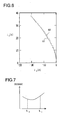
- FIG. 6 is a graph showing a comparison between an ideal maximum torque control and a control by the motor drive system shown in Fig. 1.
- Fig. 7 is a graph showing a relationship between motor current and the q-axis inductance as an operation parameter under the condition that a ⁇ -axis current is zero.
- Fig. 8 is a vector diagram showing an operation of a motor shown in Fig. 1.
- Fig. 9 is a block diagram showing a variation of a position/speed estimator shown in Fig. 3.
- Fig. 10 is a block diagram showing a general structure of a motor drive system according to a second embodiment of the present invention.
- Fig. 11 is an analytic model diagram of a motor according to the second embodiment of the present invention.
- Fig. 12 is an analytic model diagram of the motor according to the second embodiment of the present invention.
- Fig. 13 is a diagram showing an example of a current vector locus of motor current that flows in the motor shown in Fig. 10.
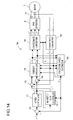
- Fig. 14 is a block diagram showing a structure of the motor drive system shown in Fig. 10.
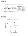
- Fig. 15 is a block diagram showing an inside structure of the position/speed estimator shown in Fig. 14.
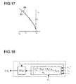
- Fig. 16 is a graph showing a dependence of each inductance on the qm-axis current in the second embodiment of the present invention.
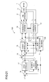
- Fig. 17 is a graph showing a comparison between an ideal maximum torque control and the control by the motor drive system shown in Fig. 10.
- Fig. 13 is a diagram showing an example of a current vector locus of motor current that flows in the motor shown in Fig. 10.
- Fig. 14 is a block diagram showing a structure of the motor drive system shown in Fig. 10.
- Fig. 15 is a block diagram
- Fig. 18 is a block diagram showing an example of an inside structure of the axial error estimator shown in Fig. 15.
- Fig. 19 is a block diagram showing a structure of a motor drive system according to a third embodiment of the present invention.
- Fig. 20 is a block diagram showing a structure of a motor drive system according to a fourth embodiment of the present invention.
- Fig. 21 is a block diagram showing a structure of a conventional motor control device.
- Fig. 22 is a block diagram showing an inside structure of the position/speed estimator shown in Fig. 21.
- Fig. 23 is a vector diagram showing an operation of a motor shown in Fig. 21.
- Fig. 24 is a block diagram showing a structure of a motor drive system according to a fifth and a sixth embodiments of the present invention.
- Fig. 25 is a diagram showing an example of a voltage vector locus of a superposed voltage generated by a superposed voltage generator shown in Fig. 24.
- Fig. 26 is a diagram showing a current vector locus of a superposed current that flows in the motor due to the superposed voltage as shown in Fig. 25.
- Fig. 27 is a diagram showing a product of a ⁇ -axis component and a ⁇ -axis component of the superposed current that flows in the motor due to the superposed voltage as shown in Fig. 25 and a direct current component of the product.
- Fig. 28 is a diagram showing a product of the ⁇ -axis component and the ⁇ -axis component of the superposed current that flows in the motor due to the superposed voltage as shown in Fig.
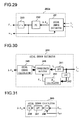
- Fig. 29 is a block diagram showing an inside structure of the estimator that can be used as the position/speed estimator shown in Fig. 24.
- Fig. 30 is a block diagram showing an inside structure of the axial error estimator shown in Fig. 29.
- Fig. 31 is a block diagram showing an inside structure of an axial error calculator shown in Fig. 30.
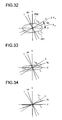
- Fig. 32 is a diagram showing an example of the current vector locus before and after coordinate rotation by a coordinate rotator shown in Fig. 30 (when perfect circle rotation voltage is superposed).
- Fig. 33 is a diagram showing an example of the current vector locus before and after coordinate rotation by the coordinate rotator shown in Fig. 30 (when elliptic rotation voltage is superposed).
- Fig. 34 is a diagram showing an example of the current vector locus before and after coordinate rotation by the coordinate rotator shown in Fig. 30 (when alternating voltage is superposed).
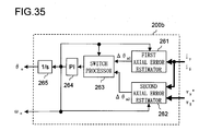
- Fig. 35 is a block diagram showing an inside structure of the position/speed estimator according to the sixth embodiment of the present invention (a first example of the estimator).
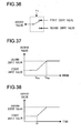
- Fig. 36 is a diagram showing a function of a switch processor shown in Fig. 35.
- Fig. 37 is a diagram showing a weighted average process performed by the switch processor shown in Fig. 35.
- Fig. 38 is a diagram showing the weighted average process performed by the switch processor shown in Fig. 35.
- Fig. 34 is a diagram showing an example of the current vector locus before and after coordinate rotation by the coordinate rotator shown in Fig. 30 (when alternating voltage is superposed).
- Fig. 35 is a block diagram showing an inside structure of the position/speed estimator according to the sixth embodiment of the present invention (a first example of the estimator).
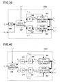
- Fig. 40 is a block diagram showing an inside structure of the position/speed estimator according to the sixth embodiment of the present invention (a third example of the estimator).
- Fig. 1 is a block diagram showing a general structure of a motor drive system according to a first embodiment of the present invention.
- Reference numeral 1 denotes a three-phase permanent magnet synchronous motor (hereinafter referred to as "motor 1" simply) including a rotor (not shown) with a permanent magnet and a stator (not shown) with an armature winding.
- the motor 1 is a salient pole machine (a motor having a salient pole) such as an interior permanent magnet synchronous motor.
- Reference numeral 2 denotes a PWM (Pulse Width Modulation) inverter, which supplies the motor 1 with three-phase alternating voltage consisting of U-phase, V-phase and W-phase in accordance with a rotor position of the motor 1.
- the voltage supplied to the motor 1 is referred to as a motor voltage (or an armature voltage) V a
- current supplied from an inverter 2 to the motor 1 is referred to as a motor current (or an armature current) I a .
- Reference numeral 3 denotes a motor control device (a position sensor-less motor control device), which estimates a rotor position and the like of the motor 1 based on the motor current I a and supplies the PWM inverter 2 with a signal for driving the motor 1 in a desired rotation speed.
- This desired rotation speed is imparted from a CPU (Central Processing Unit, not shown) or the like to the motor control device 3 as a specified motor speed value ⁇ *.
- Fig. 2 is an analytic model diagram of the motor 1.
- the armature winding means what is provided to the motor 1.
- Fig. 2 shows armature winding fixed axes of the U-phase, the V-phase and the W-phase.
- Reference numeral 1a denotes a permanent magnet that constitutes the rotor of the motor 1.
- a direction of the magnetic flux generated by the permanent magnet 1a corresponds to a d-axis while an estimated axis for control corresponding to the d-axis corresponds to a ⁇ -axis.
- a q-axis is adopted at a 90 degrees leading phase from the d-axis in the electrical angle
- a ⁇ -axis that is the estimated axis is adopted at a 90 degrees leading phase from the ⁇ -axis in the electrical angle.
- the rotating coordinate system corresponding to the real axis is a coordinate system in which the d-axis and the q-axis are chosen as the coordinate axes, which are called d-q axes.
- the rotating coordinate system for the control is a coordinate system in which the ⁇ -axis and the ⁇ -axis are chosen as coordinate axes, which are called ⁇ - ⁇ axes.
- the d-q axes is rotating, and a rotation speed thereof is called a real motor speed ⁇ .
- the ⁇ - ⁇ axes are also rotating, and a rotation speed thereof is called an estimated motor speed ⁇ e .
- a phase of the d-axis is denoted by ⁇ (a real rotor position ⁇ ) with reference to the armature winding fixed axis of the U-phase.
- ⁇ e an estimated rotor position ⁇ e
- a ⁇ -axis component, a ⁇ -axis component, a d-axis component and a q-axis component of the motor voltage V a are represented by ⁇ -axis voltage v ⁇ , ⁇ -axis voltage v ⁇ , d-axis voltage v d and q-axis voltage v q , respectively.
- a ⁇ -axis component, a ⁇ -axis component, a d-axis component and a q-axis component of the motor current I a are represented by ⁇ -axis current i ⁇ , ⁇ -axis current i ⁇ , d-axis current i d and q-axis current i q , respectively.
- R a denotes a motor resistance (a resistance of the armature winding of the motor 1).
- L d and L q denote a d-axis inductance (a d-axis component of an inductance of the armature winding of the motor 1) and a q-axis inductance (a q-axis component of an inductance of the armature winding of the motor 1), respectively.
- ⁇ a denotes an armature flux linkage attributable to the permanent magnet 1a.
- L d , L q , R a and ⁇ a are values that are determined when the motor drive system is manufactured, and the values are used for calculation by the motor control device.
- s denotes the Laplace operator in the equations that will be shown later.
- Fig. 3 is a block diagram of a motor drive system showing an inside structure of the motor control device 3 shown in Fig. 1.
- the motor control device 3 includes a current detector 11, a coordinate converter 12, a subtracter 13, a subtracter 14, a current controller 15, a magnetic flux controller 16, a speed controller 17, a coordinate converter 18, a subtracter 19 and a position/speed estimator 20 (hereinafter referred to as an "estimator 20" simply).
- Each portion constituting the motor control device 3 can use every value generated in the motor control device 3 freely, if necessary.
- the current detector 11 is made up of a Hall device or the like, for example.
- the current detector 11 detects the U-phase current i u and the V-phase current i v that are fixed axis components of the motor current I a that is supplied from the PWM inverter 2 to the motor 1.
- the coordinate converter 12 receives detection results of the U-phase current i u and the V-phase current i v from the current detector 11 and converts them into the ⁇ -axis current i ⁇ and the ⁇ -axis current i ⁇ by using the estimated rotor position ⁇ e given by the estimator 20.
- This conversion process uses the following equation (3).
- i ⁇ i ⁇ 2 ⁇ sin ⁇ e + ⁇ / 3 sin ⁇ e cos ( ⁇ e + ⁇ / 3 ) cos ⁇ e [ i u i v ]
- the estimator 20 estimates the estimated rotor position ⁇ e and the estimated motor speed ⁇ e and outputs them. A method for estimating the estimated rotor position ⁇ e and the estimated motor speed ⁇ e will be described in detail later.
- the subtracter 19 subtracts the estimated motor speed ⁇ e given by the estimator 20 from the specified motor speed value ⁇ *, and the subtraction result (a speed error) is outputted.
- the speed controller 17 generates a specified ⁇ -axis current value i ⁇ * based on the subtraction result ( ⁇ * - ⁇ e ) from the subtracter 19.
- This specified ⁇ -axis current value i ⁇ * represents a value of the current to be followed by the ⁇ -axis current is that is a ⁇ -axis component of the motor current I a .
- the magnetic flux controller 16 outputs a specified ⁇ -axis current value i ⁇ *.
- This specified ⁇ -axis current value i ⁇ * represents a value of current to be followed by the ⁇ -axis current i ⁇ that is a ⁇ -axis component of the motor current I a .
- the specified ⁇ -axis current value i ⁇ * is maintained at zero in this embodiment.
- the subtracter 13 subtracts the ⁇ -axis current i ⁇ outputted by the coordinate converter 12 from the specified ⁇ -axis current value i ⁇ * outputted by the magnetic flux controller 16 so as to calculate a current error (i ⁇ * - i ⁇ ).
- the subtracter 14 subtracts the ⁇ -axis current i ⁇ outputted by the coordinate converter 12 from the specified ⁇ -axis current value i ⁇ * outputted by the speed controller 17 so as to calculate a current error (i ⁇ * - i ⁇ ).
- the current controller 15 receives current errors calculated by the subtracters 13 and 14, the ⁇ -axis current i ⁇ and the ⁇ -axis current i ⁇ from the coordinate converter 12 and the estimated motor speed ⁇ e from the estimator 20. Then, the current controller 15 outputs the specified ⁇ -axis voltage value v ⁇ * and the specified ⁇ -axis voltage value v ⁇ * so that the ⁇ -axis current i ⁇ follows the specified ⁇ -axis current value i ⁇ * and that the ⁇ -axis current i ⁇ follows the specified ⁇ -axis current value i ⁇ *.
- the coordinate converter 18 performs inverse conversions of the specified ⁇ -axis voltage value v ⁇ * and the specified ⁇ -axis voltage value v ⁇ * based on the estimated rotor position ⁇ e given by the estimator 20, and it generates specified three-phase voltage values consisting of a specified U-phase voltage value v u *, a specified V-phase voltage value v v * and a specified W-phase voltage value v w * indicating the a U-phase component, a V-phase component and a W-phase component of the motor voltage V a so as to output them to the PWM inverter 2.
- This inverse conversion uses the following equation (4) that includes two equations.
- the PWM inverter 2 generates a pulse width modulated signal that is modulated based on the specified three-phase voltage values (v u *, v v * and v w *) indicating voltage values to be applied to the motor 1. Then, the PWM inverter 2 supplies the motor 1 with the motor current I a corresponding to the specified three-phase voltage values for driving the motor 1.
- Fig. 4 shows an example of an inside structure of the estimator 20.
- the estimator 20 shown in Fig. 4 includes an axial error estimator 30, a proportional-plus-integral calculator 31 and an integrator 32.
- the axial error estimator 30 calculates an axial error ⁇ '. This axial error ⁇ ' is different from the axial error ⁇ as described clearly later.
- An axial error estimator 130 shown in Fig. 22 calculates the axial error ⁇ by using the above equation (1), while the axial error estimator 30 shown in Fig. 4 calculates the axial error ⁇ ' by using the equation (5) below.
- ⁇ ⁇ tan - 1 ⁇ - v ⁇ * - R a + L d ⁇ s ⁇ i ⁇ + ⁇ e ⁇ L ⁇ i ⁇ v ⁇ * - R a + L d ⁇ s ⁇ i ⁇ - ⁇ e ⁇ L ⁇ i ⁇
- the equation (5) corresponds what ⁇ and L q in the above equation (1) are respectively replaced with ⁇ ' and L. Therefore, the axial error estimator 30 regards L as an operation parameter corresponding to the q-axis inductance when the rotor position is estimated so as to estimate the axial error ⁇ '.
- L an operation parameter corresponding to the q-axis inductance when the rotor position is estimated so as to estimate the axial error ⁇ '.
- the proportional-plus-integral calculator 31 performs a proportional plus integral control in cooperation with each portion constituting the motor control device 3 for realizing a PLL (Phase Locked Loop), and it calculates the estimated motor speed ⁇ e so that the axial error ⁇ ' calculated by the axial error estimator 30 converges to zero.
- the integrator 32 integrates the estimated motor speed ⁇ e outputted by the proportional-plus-integral calculator 31 so as to calculate the estimated rotor position ⁇ e .
- the estimated motor speed ⁇ e outputted by the proportional-plus-integral calculator 31 and the estimated rotor position ⁇ e outputted by the integrator 32 are imparted to each portion of the motor control device 3 that needs the values as output values of the estimator 20.
- a value between a real q-axis inductance (i.e., L q ) and a real d-axis inductance (i.e., L d ) of the motor 1 is adopted as an operation parameter corresponding to the q-axis inductance for performing the calculation of the axial error.
- L d ⁇ L q is satisfied, of course.
- the operation parameter L is determined so as to satisfy the inequality (7) below.
- the axial error ⁇ ' that is obtained by adopting the L that was set as described above as the operation parameter corresponding to the q-axis inductance is naturally different from the axial error ⁇ . For this reason, even if the PLL control is performed so that the axial error ⁇ ' converges to zero, a deviation (i.e., an axial error that is not zero) may occur between the d-axis and the ⁇ -axis.
- this deviation is generated purposely, and the deviation is utilized for setting the specified ⁇ -axis current value i ⁇ * outputted by the magnetic flux controller 16 to zero.
- a control similar to the maximum torque control is performed. This control will be examined as follows.
- L q ' represents a value of the q-axis inductance as the operation parameter that is used in the calculation equation for estimating the rotor position
- (L q - L q ') represents an error between the operation parameter and a true q-axis inductance
- the equation (10) of the d-axis current i d matching the maximum torque control is substituted into the equation (9) so as to solve the equation for L.
- the following equation (11) is obtained.
- the equation (10) is generally known and the maximum torque control can be obtained by supplying the motor 1 with the d-axis current i d that satisfied the equation (10) in accordance with the q-axis current i q .
- L in the equation (11) indicates a value of the q-axis inductance as the operation parameter to be adopted by the axial error estimator 30 for obtaining the maximum torque control in an ideal manner when the specified ⁇ -axis current value i ⁇ * is set to zero.
- L in the equation (11) is a function of the q-axis current i q .
- the relationship between i q and L is shown by the curve 60 in Fig. 5.
- a value of L matching the maximum torque control is approximately within the range of 0.003-0.0042 [H] under the condition of 1 [A] ⁇ i q ⁇ 40 [A].
- the operation parameter L that satisfies the above inequality (6) or (7) is adopted, and the specified ⁇ -axis current value i ⁇ * is set to zero, so that a control similar to the maximum torque control is realized.
- the solid line 61 is a curve showing the relationship between the d-axis current i d and the q-axis current i q when the maximum torque control is performed in an ideal manner.
- the broken line 62 and the solid line 61 show curved that are very similar to each other as understood from Fig. 6.
- the value of the specified ⁇ -axis current value i ⁇ * is not required to be precisely zero but can be a value of approximately zero (i.e., i ⁇ * ⁇ 0).
- "zero" concerning a value of the specified ⁇ -axis current value i ⁇ * should be interrupted to be "substantial zero" having a certain extent of range. If the i ⁇ * is not precisely zero, a control similar to the maximum torque control can be realized as long as the i ⁇ * can be regarded to be substantially zero.
- a value of the operation parameter L is selected from a range that satisfies the above inequality (6) or (7) so that a control similar to the maximum torque control is realized as described above. More specifically, the specified ⁇ -axis current value i ⁇ * is set to a predetermined value of zero or close to zero so that the ⁇ -axis current i ⁇ is the predetermined value and the motor 1 is given a predetermined load torque. Then, in this state, a value of the operation parameter L such that the motor current I a becomes a minimum value is selected from the range satisfying the above inequality (6) or (7).
- the L becomes an operation parameter for realizing the maximum torque control in an ideal manner at the predetermined load torque. Note that such a value of the operation parameter L is examined and set in a designing stage.
- the operation parameter L may be altered in accordance with a value of the q-axis current i q (in accordance with a value of the specified ⁇ -axis current value i ⁇ *) along the curve 60 shown in Fig. 5.
- the specified ⁇ -axis current value i ⁇ * is set to a predetermined value of zero or close to zero so that the ⁇ -axis current i ⁇ becomes the predetermined value, and a predetermined load condition is given to the motor 1.
- a value of the operation parameter L such that losses in the motor 1 (a copper loss and an iron loss) becomes a minimum value is selected from the range satisfying the above inequality (6) or (7).
- a value of L that gives a minimum value to the loss under the condition of i ⁇ * ⁇ 0 exists between L d and L q similarly to the case of the maximum torque control. Even if various values are adopted as the values of ⁇ a , L d and L q , such L satisfies the above inequality (7).
- the L becomes an operation parameter for realizing the maximum efficiency control under the predetermined load condition.
- the predetermined load condition means, for example, the condition of rotating the motor 1 at a predetermined rotation speed or the condition of giving the motor 1 a predetermined load torque.
- K cp , K sp and K p denote constants of proportionality (proportional gains), while K ci , K si and K i denote constants of integration (integral gains), which are preset in a designing stage of the motor drive system.
- the above-mentioned method for estimating a rotor position performed by the estimator 20 is merely an example, and various methods of estimation can be adopted.
- any estimation method can be adopted as long as it is an estimation method that uses an operation parameter corresponding to the q-axis inductance of the motor 1.
- a method described in the first non-patent document may be used for estimating a rotor position.
- the axial error ⁇ is calculated by using the following equation (15). If reference numerals and symbols in this embodiment are used, e ⁇ and e ⁇ respectively represent the ⁇ -axis component and the ⁇ -axis component of the induction voltage generated by rotation of the motor 1 and an armature flux linkage ⁇ a of the permanent magnet 1a.
- s represents the Laplace operator
- g represents a gain of a disturbance observer.
- the axial error estimator 30 should calculate the axial error ⁇ ' by using the following equation (16).
- the equation (16) is what ⁇ and L q in the above equation (15) are replaced with ⁇ ' and L, respectively.
- the proportional-plus-integral calculator 31 calculates the estimated motor speed ⁇ e
- the integrator 32 calculates the estimated rotor position ⁇ e so that the axial error ⁇ ' converges to zero.
- a deviation may occur between the d-axis and the ⁇ -axis.
- JP-A-2004-96979 or other method may be used for estimating a rotor position.
- an equation of the extension induction voltage (the extended electromotive force) on the real axis is usually expressed as the following equation (17).
- E ex in the equation (17) is expressed in the equation (18), which is called an extension induction voltage (an extended electromotive force).
- p in the following equations denotes a differential operator.
- the second term on the right-hand side of the equation (18) that is a differential term of the q-axis current is sufficiently smaller than ⁇ ex and can be regarded as zero.
- the third term on the right-hand side of the equation (19) is also smaller than ⁇ ex sufficiently and can be regarded as zero. Therefore, ignoring the second term on the right-hand side of the equation (18) and the third term on the right-hand side of the equation (19), the equation (19) becomes the following equation (21).
- Fig. 8 shows a vector diagram indicating the relationship among voltages of the portions of the motor 1, and so on.
- the extension magnetic flux ⁇ ex is a sum of a magnetic flux ⁇ a generated by the permanent magnet and a magnetic flux (L d - L q )i d generated by the d-axis current, so the vector thereof has the same direction as the d-axis.
- the vector represented by L q •I a is a vector of the magnetic flux generated by the q-axis inductance and the motor current l a
- the reference numeral 70 represents a composite magnetic flux vector of ⁇ ex and L q ⁇ I a .
- the magnetic flux generated by the permanent magnet is sufficiently larger than the magnetic flux generated by the d-axis current, i.e., ⁇ a is sufficiently larger than (L d - L q )i d . Therefore, it is regarded that ⁇ ex has a constant value, i.e., ⁇ ex ⁇ ⁇ a . Then, supposing that the axial error ⁇ is so small that an approximation sin ⁇ is satisfied, the following equation (23) holds with reference to the equation (22).
- ⁇ ⁇ can be approximated to equal to the ⁇ -axis component of the armature flux linkage ⁇ a (i.e., a ⁇ -axis magnetic flux that is a magnetic flux component parallel to the ⁇ -axis of the permanent magnet 1a of the motor 1 (see Fig. 2)). Therefore, it is approximated that ⁇ ⁇ ⁇ (a constant value) ⁇ ⁇ . For this reason, when this ⁇ ⁇ is controlled to converge to zero, the axial error ⁇ also converges to zero. In other words, a rotor position or a motor speed can be estimated based on ⁇ ⁇ .
- the estimator 20 shown in Figs. 3 and 4 can be replaced with an estimator 20a shown in Fig. 9.
- the estimator 20a includes a ⁇ -axis magnetic flux estimator 33, a proportional-plus-integral calculator 31a and an integrator 32a. If the axial error ⁇ is converged to zero, the ⁇ -axis magnetic flux estimator 33 should estimate a ⁇ -axis magnetic flux ⁇ ⁇ . However, similarly to the idea described above, in order to generate a deviation purposely between the d-axis and the ⁇ -axis, the ⁇ -axis magnetic flux estimator 33 estimates a ⁇ -axis magnetic flux ⁇ ⁇ ' in accordance with the following equation (24).
- the proportional-plus-integral calculator 31 a is similar to the proportional-plus-integral calculator 31 shown in Fig. 4, and it cooperate with each portion constituting the motor control device 3 so as to perform the proportional plus integral control.
- the proportional-plus-integral calculator 31a calculates the estimated motor speed ⁇ e so that the ⁇ -axis magnetic flux ⁇ ⁇ ' calculated by the ⁇ -axis magnetic flux estimator 33 converges to zero.
- the integrator 32a integrates the estimated motor speed ⁇ e outputted by the proportional-plus-integral calculator 31 a so as to calculate the estimated rotor position ⁇ e .
- the estimated motor speed ⁇ e outputted by the proportional-plus-integral calculator 31a and the estimated rotor position ⁇ e outputted by the integrator 32a are imparted to portions of the motor control device 3 that need the values as output values of the estimator 20a.
- the term including L d is multiplied by i ⁇ , so a value of the term is relatively small.
- L a value of L d in the equation (24) that is used for the estimation.
- a high efficiency operation of the salient pole machine can be realized by a control similar to a control that is used for a non-salient pole machine (such as a surface magnet synchronous motor) that does not utilize a reluctance torque. Therefore, it is unnecessary to change the control by distinguishing a difference of a structure for embedding a magnet, for example, resulting in a high flexibility. This high flexibility is also true in the case where the equations (5) and (16) and the others are used.
- the approximation ⁇ ex ⁇ ⁇ a is used in the equation (23), it is possible to estimate the ⁇ -axis magnetic flux without using this approximation.
- the ⁇ -axis magnetic flux ⁇ ⁇ ' may be estimated in accordance with the following equation (25).
- L that satisfies the above inequality (6) or (7) is used as the operation parameter corresponding to the q-axis inductance instead of a real value of L q .
- ⁇ ⁇ ⁇ ⁇ ⁇ a ( L d + L ) i ⁇ + ⁇ a ⁇ v ⁇ * - ( L d ⁇ s + R a ) i ⁇ ⁇ e + L ⁇ i ⁇
- Fig. 10 is a block diagram of a motor drive system according to the second embodiment.
- the motor drive system according to the second embodiment includes a motor 1, an inverter 2 and a motor control device 3 a.
- the motor control device 3a estimates a rotor position or the like of the motor 1 based on the motor current I a , and it supplies the PWM inverter 2 with a signal for rotating the motor 1 at a desired rotation speed.
- This desired rotation speed is supplied from a CPU (Central Processing Unit) or the like (not shown) to the motor control device 3a as a specified motor speed value ⁇ *.
- Figs. 11 and 12 are analytic model diagrams of the motor 1, which are applied to this embodiment.
- Fig. 11 shows armature winding fixed axes in the U-phase, the V-phase and the W-phase.
- a d-axis, a q-axis, a ⁇ -axis, a ⁇ -axis, a real rotor position ⁇ , an estimated rotor position ⁇ e , an axial error ⁇ , a real motor speed ⁇ and an estimated motor speed ⁇ e are defined in the same manner as in the first embodiment (see Fig. 2).
- a rotation axis having the same direction as a vector of current to be supplied to the motor 1 when the maximum torque control is realized is defined as a qm-axis.
- the axis lagging behind the qm-axis by 90 degrees in electrical angle is defined as dm-axis.
- Coordinate axes consisting of the dm-axis and the qm-axis are called as dm-qm axes.
- motor current for realizing the maximum torque control has a positive q-axis component and a negative d-axis component. For this reason, the qm-axis leads the q-axis in phase. In Figs. 11 and 12, the anticlockwise direction is the leading direction in phase.
- a phase (an angle) of the q-axis viewed from the qm-axis is denoted by ⁇ m
- a phase (an angle) of the qm-axis viewed from the ⁇ -axis is denoted by ⁇ m
- a phase of the d-axis viewed from the dm-axis is also denoted by ⁇ m
- a phase of the dm-axis viewed from the ⁇ -axis is also denoted by ⁇ m
- ⁇ m is a leading angle of the qm-axis (or the dm-axis) viewed from the q-axis (or the d-axis).
- ⁇ m denotes an axial error between the qm-axis and the ⁇ -axis (or an axial error between the dm-qm axes and the ⁇ - ⁇ axes).
- the dm-axis leads the d-axis in phase.
- ⁇ m has a negative value.
- ⁇ m has a negative value.
- the vectors (E m and the like) shown in Fig. 12 will be described later.
- the dm-axis component and the qm-axis component of the motor current I a are represented by a dm-axis current i dm and a qm-axis current i qm , respectively.
- the dm-axis component and the qm-axis component of the motor voltage V a are represented by a dm-axis voltage v dm and a qm-axis voltage v qm , respectively.
- the axial error ⁇ m between the qm-axis (the dm-axis) and the ⁇ -axis (the ⁇ -axis) is estimated, and the ⁇ -axis that is an estimated axis is converged to the dm-axis (i.e., the axial error ⁇ m is converged to zero).
- the motor current I a is decomposed into the qm-axis current i qm that is parallel to the qm-axis and the dm-axis current i dm that is parallel to the dm-axis, so as to perform a vector control of the motor 1.
- the current locus of the motor current I a when the maximum torque control is performed is located on the qm-axis as shown by the solid line 82 in Fig. 13. Therefore, when the maximum torque control is performed, the complicated calculation of the specified ⁇ -axis current value i ⁇ * as shown in the above equation (2) is not necessary, so that the calculation load can be reduced.
- the specified ⁇ -axis current value i ⁇ * is set similarly to the first embodiment. More specifically, for example, the specified ⁇ -axis current value i ⁇ * is set to a predetermined value of zero or close to zero regardless of a value of i ⁇ .
- Equation (32) When the equation (32) is used for modifying the equation (30), the equation (33) is obtained.
- E m is expressed in the equation (34).
- L q1 is a virtual inductance depending on ⁇ m .
- L q1 is determined for convenience so as to regard E ex ⁇ sin ⁇ m on the second term on the right-hand side of the equation (30) as a voltage drop by the virtual inductance. Note that L q1 has a negative value.
- the equation (36) is modified as the following equation (38). More specifically, similarly to the modification of the equation (26) into the equation (28), the equation (36) on the dm-qm axes is converted into the equation on the ⁇ - ⁇ axes by the coordinate conversion, so that the equation (38) is obtained.
- E exm ⁇ ( L d - L q ⁇ i d + ⁇ a ) - ( L d - L q ) p ⁇ i q ⁇ cos ⁇ m + ⁇ ⁇ L d - L m ⁇ i dm ⁇ ⁇ ( L d - L q ⁇ i ⁇ ⁇ sin ⁇ m + ⁇ a ) - ( L d - L q ) p ⁇ i q ⁇ cos ⁇ m + ⁇ ⁇ L q - L m ⁇ i dm ⁇ ⁇ ⁇ L d - L q ⁇ i ⁇ ⁇ sin ⁇ m + ⁇ a ⁇ cos ⁇ m
- E ex can be called an extension induction voltage vector (an extended electromotive force vector).
- the extension induction voltage vector E ex is an induction voltage vector on the q-axis.
- the extension induction voltage vector E ex is decomposed into an induction voltage vector on the qm-axis and an induction voltage vector on the dm-axis.
- the induction voltage vector on the qm-axis obtained by this decomposition is E m .
- an induction voltage vector (E ex ⁇ sin ⁇ m ) on the dm-axis represented by the reference numeral 80 in Fig. 12 obtained by this decomposition is the voltage drop vector by the virtual inductance L q1 .
- E exm is what is obtained by adding ⁇ (L q - L m )i dm to E m . Therefore, in the rotating coordinate system, E exm is an induction voltage vector on the qm-axis similarly to E m . When the maximum torque control is performed, E exm matches E m substantially because i dm ⁇ 0 as described above.
- E ex is an induction voltage generated by ⁇ ex that is a flux linkage of the motor 1 and a rotation of the motor 1 (see above equation (20)).
- ⁇ ex can be calculated when E ex is divided by ⁇ (however, the transient term (the second term on the right-hand side) of E ex of the equation (27) is ignored).
- the flux linkage vector ⁇ ex is a flux linkage vector on the d-axis.
- the flux linkage vector ⁇ ex is decomposed into a flux linkage vector on the qm-axis and a flux linkage vector on the dm-axis.
- ⁇ m E m / ⁇ .
- a flux linkage vector ( ⁇ ex ⁇ sin ⁇ m ) on the qm-axis represented by the reference numeral 81 in Fig. 12 obtained by this decomposition is the magnetic flux vector by the virtual inductance L q1 .
- ⁇ exm E exm / ⁇
- ⁇ exm is what is obtained by adding (L q - L m )i dm to ⁇ m . Therefore, in the rotating coordinate system, ⁇ exm is a flux linkage vector on the dm-axis similarly to ⁇ m .
- ⁇ exm matches ⁇ m substantially since i dm ⁇ 0 as described above.
- Fig. 14 is a block diagram of the motor drive system showing an inside structure of the motor control device 3 a shown in Fig. 10.
- the motor control device 3 a includes a current detector 11, a coordinate converter 12, a subtracter 13, a subtracter 14, a current controller 15, a magnetic flux controller 16, a speed controller 17, a coordinate converter 18, a subtracter 19 and a position/speed estimator 40 (hereinafter referred to as an "estimator 40" simply).
- the motor control device 3a shown in Fig. 14 has a structure in which the estimator 20 in the motor control device 3 shown in Fig. 3 is replaced with the estimator 40.
- Each portion constituting the motor control device 3a can use every value generated in the motor control device 3a freely, if necessary.
- the current detector 11 detects the U-phase current i u and the V-phase current i v that are fixed axis components of the motor current I a.
- the coordinate converter 12 receives detection results of the U-phase current i u and the V-phase current i v from the current detector 11 and converts them into the ⁇ -axis current i ⁇ and the ⁇ -axis current i ⁇ by using the estimated rotor position ⁇ e given by the estimator 40. This conversion process uses the above equation (3) similarly to the first embodiment.
- the estimator 40 estimates the estimated rotor position ⁇ e and the estimated motor speed ⁇ e and outputs them. A method for specific estimation performed by the estimator 40 will be described later.
- the subtracter 19 subtracts the estimated motor speed ⁇ e given by the estimator 40 from the specified motor speed value ⁇ *, and the subtraction result (a speed error) is outputted.
- the speed controller 17 generates a specified ⁇ -axis current value i ⁇ * based on the subtraction result ( ⁇ * - ⁇ e ) from the subtracter 19.
- the magnetic flux controller 16 outputs a specified ⁇ -axis current value i ⁇ *.
- This specified ⁇ -axis current value i ⁇ * is set in the same manner as in the first embodiment described above. For example, i ⁇ * is set to a predetermined value of zero or close to zero.
- the subtracter 13 subtracts the ⁇ -axis current i ⁇ outputted by the coordinate converter 12 from the specified ⁇ -axis current value i ⁇ * outputted by the magnetic flux controller 16 so as to calculate a current error (i ⁇ * - i ⁇ ).
- the subtracter 14 subtracts the ⁇ -axis current i ⁇ outputted by the coordinate converter 12 from the specified ⁇ -axis current value i ⁇ * outputted by the speed controller 17 so as to calculate a current error (i ⁇ * - i ⁇ ).
- the current controller 15 receives current errors calculated by the subtracters 13 and 14, the ⁇ -axis current i ⁇ and the ⁇ -axis current is from the coordinate converter 12 and the estimated motor speed ⁇ e from the estimator 40. Then, the current controller 15 outputs the specified ⁇ -axis voltage value v ⁇ * and the specified ⁇ -axis voltage value v ⁇ * so that the ⁇ -axis current i ⁇ follows the specified ⁇ -axis current value i ⁇ * and that the ⁇ -axis current i ⁇ follows the specified ⁇ -axis current value i ⁇ *.
- the coordinate converter 18 performs inverse conversions of the specified ⁇ -axis voltage value v ⁇ * and the specified ⁇ -axis voltage value v ⁇ * based on the estimated rotor position ⁇ e given by the estimator 40, and it generates specified three-phase voltage values consisting of v u *, v v * and v w * so as to output them to the PWM inverter 2.
- This inverse conversion uses the above equation (4) similarly to the first embodiment.
- the PWM inverter 2 supplies the motor 1 with the motor current I a corresponding to the specified three-phase voltage values for driving the motor 1.
- Fig. 15 shows an example of an inside structure of the estimator 40.
- the estimator 40 shown in Fig. 15 includes an axial error estimator 41, a proportional-plus-integral calculator 42 and an integrator 43.
- the proportional-plus-integral calculator 42 and the integrator 43 are respectively similar to the proportional-plus-integral calculator 31 and the integrator 32 shown in Fig. 4.
- the axial error estimator 41 calculates an axial error ⁇ m by using a whole or a part of values of v ⁇ *, v ⁇ *, i ⁇ and i ⁇ .
- the proportional-plus-integral calculator 42 performs a proportional plus integral control in cooperation with each portion constituting the motor control device 3 a for realizing a PLL (Phase Locked Loop), and it calculates the estimated motor speed ⁇ e so that the axial error ⁇ m calculated by the axial error estimator 41 converges to zero.
- the integrator 43 integrates the estimated motor speed ⁇ e outputted by the proportional-plus-integral calculator 42 so as to calculate the estimated rotor position ⁇ e .
- the estimated motor speed ⁇ e outputted by the proportional-plus-integral calculator 42 and the estimated rotor position ⁇ e outputted by the integrator 43 are imparted to each portion of the motor control device 3a that needs the values as output values of the estimator 40.
- a method for calculating the axial error ⁇ m by the axial error estimator 41 various calculation methods can be used.
- a method for calculating the axial error ⁇ m by the axial error estimator 41 in other words, as a method for calculating ⁇ e by the estimator 40, a first, a second, a third, a fourth and a fifth calculation methods will be exemplified.
- the axial error estimator 41 uses values of v ⁇ *, v ⁇ * and ⁇ e as values of v ⁇ , v ⁇ and ⁇ in the equations, respectively.
- contents described in each calculation method (a method for determining a value of L m or the like) can be applied to every other calculation method and every other embodiment that will be described later.
- the induction voltage E ex generated in the motor 1 is decomposed into an induction voltage vector on the qm-axis and an induction voltage vector on the dm-axis for consideration. Then, a induction voltage vector E exm that is the induction voltage vector on the qm-axis ( ⁇ E m , see Fig. 12) is used for calculating the axial error ⁇ m , thereby a phase ( ⁇ e ) of the ⁇ -axis that is an estimated axis for the control is calculated (i.e., a rotor position is estimated).
- the axial error estimator 41 can ignore differential terms pL d i ⁇ and pL d i ⁇ when it calculates ⁇ m by using the equation (41).
- the following equation (42) is used for calculating a value of L m that is necessary for calculating ⁇ m .
- the equation (45) of the d-axis current i d matching the maximum torque control and the equation (43) that is a relationship equation (an approximated equation) among i d , i q and i qm are used for deforming the above equation (42).
- L m becomes a function of i qm (i.e., i d and i q are eliminated from the calculation equation of L m ). Therefore, the axial error estimator 41 can calculate a value of L m that is expressed in a function of i qm based on i ⁇ when the equation "i ⁇ ⁇ i qm " is supposed.
- Fig. 16 shows a graph indicating dependence of L d , L q and L m on i qm under an example of certain values (supposing i ⁇ * ⁇ 0).
- a value of L m depends on i qm in such a way that it increases as i qm increases.
- L m that is defined in this embodiment corresponds to the operation parameter L in the first embodiment. It is understood that a value of L m matching the maximum torque control exists on the fairly L d side from L q similarly to L (see Figs. 5 and 7 and others).
- a value of L m is determined so as to satisfy the following inequality (46) or (47) accordingly, in the same manner as in the first embodiment.
- the motor control device 3 a in this embodiment can realize a control similar to the maximum torque control by generating a deviation purposely between the d-axis and the ⁇ -axis similarly to the first embodiment and by setting i ⁇ * ⁇ 0. L d ⁇ L m ⁇ L q L d ⁇ L m ⁇ L d + L q / 2
- L m may have a fixed value. More specifically, it is possible to adopt a fixed value regardless of a value of i ⁇ as a value of L m .
- a relationship between the d-axis current i d and the q-axis current i q when L m is a predetermined fixed value is shown by the solid line 83 in Fig. 17.
- a broken line 84 is a curve showing the relationship between the d-axis current i d and the q-axis current i q when the maximum torque control is performed in an ideal manner.
- the solid line 83 and the broken line 84 shows curves that are very similar to each other as understood from Fig. 17.
- the induction voltage vector E exm is used for calculating the axial error ⁇ m , thereby a phase ( ⁇ e ) of the ⁇ -axis that is an estimated axis for the control is calculated (i.e., a rotor position is estimated).
- the ⁇ -axis component E exm ⁇ of the induction voltage vector E exm is not used. More specifically, the following equation (48) is used for calculating the axial error ⁇ m .
- the axial error estimator 41 can ignore the differential term pL d i ⁇ when calculating the ⁇ m by using the equation (48).
- a value of L m is determined by the method similar to the method in the first calculation method.
- the above equation (39) is used for calculating E exm in the equation (48).
- the following equation (49), (50) or (51) can be used, for example.
- the equation (49) is an approximate expression of the equation (37) using an approximation "p ⁇ m ⁇ 0, i dm ⁇ 0, and (L d - L q )(pi q ) ⁇ 0", and the equation (50) is an approximate expression of the equation (49) further using an approximation "cos ⁇ m ⁇ 1 ", and the equation (51) is an approximate expression of the equation (50) further using an approximation "(L d - L q )i ⁇ sin ⁇ m ⁇ ⁇ a ".
- ⁇ e is used as a value of ⁇ when the equation (49), (50) or (51) is used.
- Equation (40) In order to calculate ⁇ m included in the equation (49) or the like, the above equation (40) is used. As understood from the equation (40), ⁇ m is a function of i ⁇ , and E exm is also a function of i ⁇ . Since the calculation of E exm is complicated, it is desirable to use an approximate expression for the calculation. In addition, it is also preferable to prepare values of E exm corresponding to i ⁇ as table data in advance so that a value of E exm can be obtained by referring to the table data.
- a flux linkage ⁇ ex that has linkage with the armature winding of the motor 1 is decomposed into a flux linkage vector on the qm-axis and a flux linkage vector on the dm-axis for consideration. Then, a flux linkage vector ⁇ exm ( ⁇ ⁇ m , see Fig. 12) that is the flux linkage vector on the dm-axis is used for calculating the axial error ⁇ m , thereby a phase ( ⁇ e ) of the ⁇ -axis that is an estimated axis for the control is calculated (i.e., a rotor position is estimated).
- the axial error estimator 41 can ignore differential terms pL d i ⁇ and pL d i ⁇ when it calculates ⁇ m by using the equation (52).
- a value of L m is determined by the method similar to the method in the first calculation method.
- the flux linkage vector ⁇ exm is used for calculating the axial error ⁇ m , thereby a phase ( ⁇ e ) of the ⁇ -axis that is an estimated axis for the control is calculated (i.e., a rotor position is estimated).
- the ⁇ -axis component ⁇ exm ⁇ of the flux linkage vector ⁇ exm is not used. More specifically, the following equation (53) is used for calculating the axial error ⁇ m .
- the axial error estimator 41 can ignore the differential term pL d i ⁇ when it calculates ⁇ m by using the equation (53).
- a value of L m is determined by the method similar to the method in the first calculation method.
- Equation (53) In order to calculate ⁇ exm in the equation (53), an equation obtained by dividing both sides of the above equation (39) by ⁇ is used. As an approximate expression for calculating ⁇ exm , the following equation (54), (55) or (56) can be used, for example. The following equation (54), (55) and (56) are obtained by dividing both sides of the equation (49), (50) and (51) by ⁇ , respectively. Note that ⁇ e is used as a value of ⁇ when the equation (54), (55) or (56) is used.
- ⁇ m is a function of i ⁇
- ⁇ exm is also a function of i ⁇ . Since the calculation of ⁇ exm is complicated, it is desirable to use an appropriate approximate expression for the calculation. In addition, it is also preferable to prepare values of ⁇ exm corresponding to i ⁇ as table data in advance so that a value of ⁇ exm can be obtained by referring to the table data.
- a fifth calculation method of the axial error ⁇ m will be described.
- error current between current on the dm-qm axes (current in a motor model) and current on the ⁇ - ⁇ axes is used for calculating the axial error ⁇ m , thereby a phase ( ⁇ e ) of the ⁇ -axis that is an estimated axis for the control is calculated (i.e., a rotor position is estimated).
- Equation (57) Performing discretization with a sampling period T s , the equation (57) are expressed as the following equation (58).
- i ⁇ ( n ) i ⁇ ( n ) 1 - R a L d ⁇ T s - ⁇ ⁇ n - 1 ⁇ L m L d ⁇ T s - ⁇ ⁇ n - 1 ⁇ L m L d ⁇ T s 1 - R a L d ⁇ T s [ i ⁇ ( n - 1 ) i ⁇ ( n - 1 ) ] + T s L d [ v ⁇ ( n - 1 ) v ⁇ ( n - 1 ) ] - T s L d [ E exm ⁇ ( n - 1 ) E exm ⁇ ( n - 1 ) ]
- the estimated currents i M ⁇ and i M ⁇ obtained by calculation in the axial error estimator 41 are expressed as the following equation (59) by using the estimated induction voltages E Mexm ⁇ and E Mexm ⁇ obtained by model calculation of E exm ⁇ and E exm ⁇ .
- i M ⁇ ( n ) i M ⁇ ( n ) 1 - R a L d ⁇ T s ⁇ ⁇ n - 1 ⁇ L m L d ⁇ T s - ⁇ ⁇ n - 1 ⁇ L m L d ⁇ T s 1 - R a L d ⁇ T s [ i ⁇ ( n - 1 ) i ⁇ ( n - 1 ) ] + T s L d [ v ⁇ ( n - 1 ) v ⁇ ( n - 1 ) ] - T s L d [ E Mexm ⁇ ( n - 1 ) E Mexm ⁇ ( n - 1 ) ]
- the axial error estimator 41 calculates estimated induction voltages E Mexm ⁇ and E Mexm ⁇ as estimated values of E exm ⁇ and E exm ⁇ , respectively.
- the estimated currents i M ⁇ and i M ⁇ are calculated by using L m instead of L q , the estimated currents i M ⁇ and i M ⁇ can be regarded as currents obtained by estimating the dm-axis component and the qm-axis component of the motor current I a , respectively.
- the error current ⁇ i ⁇ (or ⁇ i ⁇ ) that is a difference between the current i ⁇ (or i ⁇ ) based on the fixed axis components (i u and i v ) of the motor current I a detected by the current detector 11 and the estimated current i M ⁇ (or i M ⁇ ) obtained by calculation is expressed in the following equation (60) derived from the equation (58) and (59).
- ⁇ E exm ⁇ is an error between an induction voltage E exm ⁇ and an estimated induction voltage E Mexm ⁇ that is an estimated value of the induction voltage E exm ⁇
- ⁇ E exm ⁇ is error between an induction voltage E exm ⁇ and an estimated induction voltage E Mexm ⁇ that is an estimated value of the induction voltage E exm ⁇ .
- an error of the estimated value of the induction voltage ( ⁇ E exm ⁇ or the like) and the error current ( ⁇ i ⁇ or the like) are proportional to each other. For this reason, the error of the estimated value of the induction voltage can be converged by using the error current. More specifically, it is possible to use the estimated induction voltages E Mexm ⁇ and E Mexm ⁇ as those obtained by estimating the induction voltages E exm ⁇ and E exm ⁇ correctly (the induction voltage can be estimated correctly).
- the estimated induction voltage of this time is calculated by using the previous estimated induction voltage and the previous estimation error. More specifically, the estimated induction voltages E Mexm ⁇ and E Mexm ⁇ are calculated sequentially by using the following equation (61).
- g is a feedback gain for converging the error of the estimated value of the induction voltage.
- the axial error estimator 41 calculates the axial error ⁇ m by using the following equation (62) or (63).
- the symbol (n or n-1) in parentheses indicates a sampling timing when the discretization is performed at the sampling period T s
- n denotes a natural number, which indicates a sampling timing after (n-1).
- Each portion constituting the motor control device 3 a calculates and outputs each value sequentially every sampling period T s .
- i ⁇ (n) and i ⁇ (n) indicate i ⁇ and i ⁇ at n-th sampling timing
- i ⁇ (n-1) and i ⁇ (n-1) indicate i ⁇ and i ⁇ at (n-1)th sampling timing. This is the same for other than i ⁇ and i ⁇ .
- the motor control device 3 a performs drive and control of the motor 1 by decomposing the current flowing in the motor 1 into the qm-axis component and the dm-axis component. The effect obtained by this decomposition is as described above.
- the motor control device 3b has a structure in which the estimator 40 of the motor control device 3 a in Fig. 14 is replaced with a position/speed estimator 45 (hereinafter referred to as an estimator 45 simply), a ⁇ m calculator 46 and a computing unit 47. Except for this replacement, the motor control device 3b and the motor drive system in Fig. 19 are similar to the motor control device 3a and the motor drive system in Fig. 14. Description of structures and operations of the similar parts will be omitted.
- the estimator 45 estimates a phase of the d-axis viewed from the U-phase by using the i ⁇ , i ⁇ , v ⁇ * and v ⁇ *, and it outputs the estimated value as ⁇ dqe .
- the estimator 45 calculates the estimated motor speed ⁇ e similarly to the estimator 40 in the second embodiment. If the estimated motor speed ⁇ e outputted by the estimator 45 is obtained by differentiating ⁇ dqe , the obtained estimated motor speed ⁇ e should be actually called an estimated value of the rotation speed of the d-axis. However, in a steady state, the estimated value can be regarded to be the same as ⁇ e that is the rotation speed of the ⁇ -axis.
- a ⁇ m calculator 46 uses i ⁇ * from the speed controller 17 as is in the above equation (40) while it calculates ⁇ m by using the above equation (40). In this case, it is possible to prepare values of ⁇ m corresponding to i ⁇ * as table data in advance, so that a value of ⁇ m is obtained by referring to the table data.
- the computing unit 47 calculates ⁇ e by using ⁇ dqe outputted by the estimator 45 and ⁇ m outputted by the ⁇ m calculator 46, and the calculated ⁇ e is imparted to coordinate converters 12 and 18.
- the portion including the estimator 45, the ⁇ m calculator 46 and the computing unit 47 calculates a phase ( ⁇ e ) of the ⁇ -axis that is an estimated axis for the control.
- the structure of the third embodiment can obtain the same action and effect as the second embodiment.
- the first through the third embodiments adopt the method of estimating a rotor position by using the estimator, it is possible to detect a real rotor position. More specifically, it is possible to use a motor control device 3c shown in Fig. 20 instead of the motor control device shown in Fig. 3, 14 or 19.
- FIG. 20 is a block diagram showing a structure of the motor drive system according to the fourth embodiment.
- the motor drive system includes a motor 1, an inverter 2 and a motor control device 3c.
- the motor control device 3c includes a current detector 11, a coordinate converter 12, a subtracter 13, a subtracter 14, a current controller 15, a magnetic flux controller 16, a speed controller 17, a coordinate converter 18, a subtracter 19, a position detector 50, a differentiator 51, a ⁇ m calculator 52 and a computing unit 53.
- the motor control device 3c has a structure in which the estimator 40 shown in Fig. 14 is replaced with the position detector 50, the differentiator 51, the ⁇ m calculator 52 and the computing unit 53. Except for this replacement, the motor control device 3 c and the motor drive system shown in Fig. 20 is similar to the motor control device 3a and the motor drive system shown in Fig. 14. Each portion of the motor control device 3c can use every value generated in the motor control device 3c freely, if necessary.
- Each portion inside the motor control device 3c works not based on an estimated rotor position but based on a detected real rotor position, so ⁇ and ⁇ in the second embodiment are replaced with dm and qm in this embodiment for consideration.
- the position detector 50 is made up of a rotary encoder or the like, which detects a real rotor position ⁇ of the motor 1 and imparts the value to the differentiator 51 and the computing unit 53.
- the differentiator 51 differentiates the real rotor position ⁇ so as to calculate the real motor speed ⁇ and imparts the value to the subtracter 19, the magnetic flux controller 16 and the current controller 15.
- the speed controller 17 generates a specified qm-axis current value i qm * to be followed by the qm-axis current i qm based on the subtraction result ( ⁇ )*- ⁇ ) of the subtracter 19.
- the magnetic flux controller 16 outputs a specified dm-axis current value i dm * to be followed by the dm-axis current i dm .
- This specified dm-axis current value i dm * is set similarly to the second embodiment. More specifically, i dm * is set to be a predetermined value of zero or close to zero.
- the subtracter 13 subtracts i dm outputted by the coordinate converter 12 from i dm * outputted by the magnetic flux controller 16 so as to calculate the current error (i dm * - i dm ).
- the subtracter 14 subtracts i qm outputted by the coordinate converter 12 from i qm * outputted by the speed controller 17 so as to calculate the current error (i qm * - i qm ).
- the current controller 15 receives the current errors calculated by the subtracters 13 and 14, i dm and i qm from the coordinate converter 12 and the real motor speed ⁇ from the differentiator 51. Then the current controller 15 outputs a specified dm-axis voltage value v dm * to be followed by v dm and a specified qm-axis voltage value v qm * to be followed by v qm , so that i dm follows i dm *, and i qm follows i qm *.
- the ⁇ m calculator 52 utilizes i qm * from the speed controller 17 as i ⁇ in the above equation (40) and calculates ⁇ m by using the above equation (40). In this case, it is possible to prepare values of ⁇ m corresponding to i qm * (i ⁇ *) as table data in advance, so that a value of ⁇ m is obtained by referring to the table data.
- the computing unit 53 calculates a phase ⁇ dm of the dm-axis viewed from the U-phase by using ⁇ detected by the position detector 50 and ⁇ m calculated by the ⁇ m calculator 52, and the calculated ⁇ dm is imparted to the coordinate converters 12 and 18.
- the coordinate converter 18 converts v dm * and v qm * into the specified three-phase voltage values consisting of v u *, v v * and v w * based on the given ⁇ dm , and the value obtained by the conversion is outputted to the PWM inverter 2.
- the PWM inverter 2 supplies the motor 1 with the motor current I a corresponding to the specified three-phase voltage values so as to drive the motor 1.
- the structure of the fourth embodiment can obtain the same action and effect as the second embodiment.
- the sensor-less controls described in the second and the third embodiments are controls based on the generated induction voltage or the like, they are useful particularly when the motor 1 rotates at a high speed. However, in a low speed rotation, accuracy of the estimation is not always sufficient. In addition, it cannot be used when the rotation is stopped.
- a sensor-less control based on the dm-qm axes will be described. The control works effectively in particular at a low speed rotation or when the rotation is stopped.
- Fig. 24 is a block diagram of a motor control device 3d according to the fifth embodiment.
- the motor control device 3d includes a current detector 11, a coordinate converter 12, a subtracter 13, a subtracter 14, a current controller 15, a magnetic flux controller 16, a speed controller 17, a coordinate converter 18, a subtracter 19, a position/speed estimator 200 (hereinafter referred to an "estimator 200" simply), a superposed voltage generator 201, an adder 202 and an adder 203.
- Each portion of the motor control device 3d can use every value generated in the motor control device 3d freely, if necessary.
- the motor control device 3d is similar to motor control device 3a shown in Fig. 14 except that the superposed voltage generator 201 and the adders 202 and 203 are newly added and that the estimator 40 of the motor control device 3 a shown in Fig. 14 is replaced with the estimator 200 in the motor control device 3d. Note that the contents described in the second embodiment are applied to this embodiment as long as there is no conflict.
- the estimator 200 estimates the estimated rotor position ⁇ e and the estimated motor speed ⁇ e so as to output them. A specific estimation method performed by the estimator 200 will be described later.
- the coordinate converter 12 converts the U-phase current i u and the V-phase current i v detected by the current detector 11 into the ⁇ -axis current i ⁇ and the ⁇ -axis current i ⁇ by using the estimated rotor position ⁇ e given by the estimator 200.
- the subtracter 19 subtracts the estimated motor speed ⁇ e given by the estimator 200 from the specified motor speed value ⁇ *, and the subtraction result (a speed error) is outputted.
- the speed controller 17 generates the specified ⁇ -axis current value is* based on the subtraction result ( ⁇ * - ⁇ e ) of the subtracter 19.
- the magnetic flux controller 16 outputs the specified ⁇ -axis current value i ⁇ *.
- This specified ⁇ -axis current value i ⁇ * is set similarly to the first embodiment or the like. For example, i ⁇ * is set to a predetermined value of zero or close to zero.
- the subtracter 13 subtracts the ⁇ -axis current i ⁇ outputted by the coordinate converter 12 from the specified ⁇ -axis current value i ⁇ * outputted by the magnetic flux controller 16, so as to calculate the current error (i ⁇ *-i ⁇ ).
- the subtracter 14 subtracts the ⁇ -axis current i ⁇ outputted by the coordinate converter 12 from the specified ⁇ -axis current value i ⁇ * outputted by the speed controller 17, so as to calculate the current error (i ⁇ *-i ⁇ ).
- the current controller 15 receives the current errors calculated by the subtracters 13 and 14, the ⁇ -axis current i ⁇ and the ⁇ -axis current i ⁇ from the coordinate converter 12 and the estimated motor speed ⁇ e from the estimator 200. Then, the current controller 15 outputs the specified ⁇ -axis voltage value v ⁇ * and the specified ⁇ -axis voltage value v ⁇ *, so that the ⁇ -axis current i ⁇ follows the specified ⁇ -axis current value i ⁇ *, and the ⁇ -axis current i ⁇ follows the specified ⁇ -axis current value i ⁇ *.
- the superposed voltage generator 201 generates a superposed voltage that is superposed on the specified ⁇ -axis voltage value v ⁇ * and the specified ⁇ -axis voltage value v ⁇ *.
- This superposed voltage consists of a ⁇ -axis superposed voltage v h ⁇ * (a ⁇ -axis component of the superposed voltage) for v ⁇ * and a ⁇ -axis superposed voltage v h ⁇ * (a ⁇ -axis component of the superposed voltage) for v ⁇ *.
- the ⁇ -axis superposed voltage v h ⁇ * and the ⁇ -axis superposed voltage v h ⁇ * may be referred to as superposed voltages v h ⁇ * and v h ⁇ * as a generic name.
- the adder 202 adds the ⁇ -axis superposed voltage v h ⁇ * to the specified ⁇ -axis voltage value v ⁇ * outputted by the current controller 15, and the addition result (v ⁇ * + v h ⁇ *) is outputted to the coordinate converter 18.
- the adder 203 adds the ⁇ -axis superposed voltage v h ⁇ * to the specified ⁇ -axis voltage value v ⁇ * outputted by the current controller 15, and the addition result (v ⁇ * + v h ⁇ *) is outputted to the coordinate converter 18.
- the coordinate converter 18 performs an inverse conversion of the specified ⁇ -axis voltage value with superposed v h ⁇ * (i.e., v ⁇ * + v h ⁇ *) and the specified ⁇ -axis voltage value with superposed v h ⁇ * (i.e., v ⁇ * + v h ⁇ *) based on the estimated rotor position ⁇ e given by the estimator 200, and it generates the specified three-phase voltage values (v u *, v v * and v w *) so as to output them to the PWM inverter 2.
- a superposed voltage is added to a drive voltage for driving the motor 1 that is represented by v ⁇ * and v ⁇ * (in other words, the superposed voltage is superposed on the drive voltage).
- superposed current corresponding to the superposed voltage is added to the drive current for driving the motor 1 that is represented by the specified ⁇ -axis current value i ⁇ * and the specified ⁇ -axis current value i ⁇ *.
- the superposed voltage generated by the superposed voltage generator 201 is, for example, a high frequency rotation voltage.
- the "high frequency” means that a frequency of the superposed voltage is sufficiently higher than a frequency of the drive voltage. Therefore, a frequency of the superposed current that is added in accordance with the superposed voltage is sufficiently higher than a frequency of the drive current.
- the "rotation voltage” means a voltage such that the voltage vector locus of the superposed voltage describes a circle on the fixed coordinate axes.
- the voltage vector locus of the superposed voltage generated by the superposed voltage generator 201 describes a circle like a voltage vector locus 210 shown in Fig. 25, for example. If the superposed voltage is three-phase balanced voltages, the voltage vector locus describes a perfect circle around the origin on the rotating coordinate axes like the voltage vector locus 210.
- This rotation voltage (the superposed voltage) is a high frequency voltage that is not synchronous with the motor 1, so an application of the rotation voltage does not cause rotation of the motor 1.
- the current vector locus of the superposed current that flows in the motor 1 by the superposed voltage that describes the voltage vector locus 210 describes an ellipse having the major axis in the ⁇ -axis direction and the minor axis in the ⁇ -axis with the center on the origin of the ⁇ - ⁇ axes as shown by the current vector locus 211 in Fig. 26.
- the current vector locus 211 is a current vector locus in the case where an axial error ⁇ between the d-axis and the ⁇ -axis is zero.
- the current vector locus of the superposed current becomes an ellipse as shown by the current vector locus 212, which has the major axis that does not match the ⁇ -axis direction. More specifically, if the axial error ⁇ is not zero, the current vector locus 211 is inclined with the center at the origin of the ⁇ - ⁇ axes so that the current vector locus 212 is described.
- the ⁇ -axis component and the ⁇ -axis component of the superposed current are referred to as a ⁇ -axis superposed current i h ⁇ and a ⁇ -axis superposed current i h ⁇ , respectively.
- the product of them includes a direct current component depending on a gradient of the ellipse expressed in the current vector locus 212.
- the product (i h ⁇ ⁇ i h ⁇ ) has a positive value in the first and third quadrants of the current vector locus, while it has a negative value in the second and fourth quadrants thereof.
- the direct current component is not included if the ellipse is not inclined (in the case of the current vector locus 211), the direct current component is included if the ellipse is inclined (in the case of the current vector locus 212).
- I, II, III and IV shown in Fig. 26 represent the first, second, third and fourth quadrants on the ⁇ - ⁇ axes.
- Fig. 27 shows a product (i h ⁇ ⁇ i h ⁇ ) in the case where the axial error ⁇ is zero and the direct current component of the product by curves 220 and 221, respectively, in which the horizontal axis represents time.
- Fig. 28 shows a product (i h ⁇ ⁇ i h ⁇ ) in the case where the axial error ⁇ is not zero and the direct current component of the product by curves 222 and 223, respectively, in which the horizontal axis represents time.
- this direct current component increases as a value of the axial error ⁇ increases (i.e., it is approximately proportional to the axial error ⁇ ). Therefore, if this direct current component is controlled to converge to zero, the axial error ⁇ converges to zero.
- the estimator 200 shown in Fig. 24 performs an estimation operation noting this point. However, the estimation operation is performed so that not the axial error ⁇ between the d-axis and the ⁇ -axis but the axial error ⁇ m between the dm-axis and the ⁇ -axis converges to zero for estimating the dm-qm axes.
- Fig. 29 shows a block diagram of the inside structure of the estimator (the position/speed estimator) 200a as an example of the estimator 200.
- the estimator 200a includes an axial error estimator 231, a proportional-plus-integral calculator 232 and an integrator 233.
- the proportional-plus-integral calculator 232 and the integrator 233 are similar to the proportional-plus-integral calculator 31 and the integrator 32 shown in Fig. 4, respectively.
- the axial error estimator 231 calculates the axial error ⁇ m by using i ⁇ and i ⁇ .
- the proportional-plus-integral calculator 232 performs the proportional plus integral control in cooperation with each portion of the motor control device 3d so as to realize a PLL (Phase Locked Loop). Then, the proportional-plus-integral calculator 232 calculates the estimated motor speed ⁇ e so that the axial error ⁇ m calculated by the axial error estimator 231 converge to zero.
- the integrator 233 integrates the estimated motor speed ⁇ e outputted by the proportional-plus-integral calculator 232 so as to calculate the estimated rotor position ⁇ e .
- the estimated motor speed ⁇ e outputted by the proportional-plus-integral calculator 232 and the estimated rotor position ⁇ e outputted by the integrator 233 are both imparted to each part of the motor control device 3d that needs the values as output values of the estimator 200a.
- the estimated motor speed ⁇ e is also imparted to the axial error estimator 231.
- the axial error estimator 231 includes a BPF (band pass filter) 241, a LPF (low pass filter) 242, a ⁇ m calculator 243, a coordinate rotator 244 and an axial error calculator 245.
- the axial error calculator 245 includes a multiplier 246, a LPF 247 and a coefficient multiplier 248.
- a frequency (an electrical angle speed on the ⁇ - ⁇ coordinate axes) of the superposed voltages v h ⁇ * and v h ⁇ * generated by the superposed voltage generator 201 is represented by ⁇ h .
- the BPF 241 extracts a frequency component of ⁇ h from the ⁇ -axis current i ⁇ and the ⁇ -axis current i ⁇ outputted by the coordinate converter 12 shown in Fig. 24, and it outputs the ⁇ -axis superposed current i h ⁇ and the ⁇ -axis superposed current i h ⁇ .
- the BPF 241 is a band pass filter having a pass band including the frequency of ⁇ h , which receives the i ⁇ and i ⁇ as input signals. Typically, the center frequency of the pass band is ⁇ h .
- the BPF 241 removes frequency components of the drive current.
- the LPF 242 removes a frequency component of ⁇ h that is a high frequency component from the ⁇ -axis current i ⁇ and the ⁇ -axis current i ⁇ outputted by the coordinate converter 12 shown in Fig. 24, and the result is sent to the ⁇ m calculator 243. In other words, the LPF 242 removes the component of the superposed current (i h ⁇ and i h ⁇ ) from the ⁇ -axis current i ⁇ and the ⁇ -axis current i ⁇ .
- the ⁇ m calculator 243 calculates a phase ⁇ m based on values of the ⁇ -axis current i ⁇ and the ⁇ -axis current i ⁇ from which the frequency component of ⁇ h is removed (see Fig. 11). Specifically, a value of the ⁇ -axis current i ⁇ from which the frequency component of ⁇ h is removed is used as is in the above equation (40), while ⁇ m is calculated by using the above equation (40). In this case, it is possible to prepare values of ⁇ m corresponding to i ⁇ as table data in advance, so that a value of ⁇ m is obtained by referring to the table data.
- the coordinate rotator 244 uses the following equation (64) and performs the coordinate rotation of the current vector i h formed by the superposed current i h ⁇ and i h ⁇ to the extent corresponding to the phase represented by ⁇ m for calculating the current vector i hm .
- the value of ⁇ m calculated by the ⁇ m calculator 243 is used.
- the current vectors i h and i hm are expressed in the following equation (65a) and (65b).
- the current i h ⁇ and i h ⁇ are orthogonal two-axes components that form the current vector i h , which are the ⁇ -axis component and the ⁇ -axis component of the current vector i h .
- the current vectors i hm ⁇ and i hm ⁇ are orthogonal two-axes components that form the current vector i hm .
- the current vectors i hm ⁇ and i hm ⁇ calculated by the coordinate rotator 244 are sent to the axial error calculator 245.
- i hm ⁇ i hm ⁇ cos ⁇ m sin ⁇ m - sin ⁇ m cos ⁇ m [ i h ⁇ i h ⁇ ]
- i h [ i h ⁇ i h ⁇ ]
- i hm [ i hm ⁇ i hm ⁇ ]
- Fig. 32 shows an example of the current vector locus before and after the coordinate rotation
- meaning of the coordinate rotation will be described as a supplemental explanation.
- a perfect circle rotation voltage is superposed, i.e., the case where a superposed voltage like drawing the voltage vector locus 210 shown in Fig. 25 is applied.
- the locus of the current vector i h on the rotating coordinate axes describes an ellipse that is symmetric about the d-axis (i.e., an ellipse in which the d-axis direction matches the major axis direction), similarly to the current vector locus 251.
- the coordinate rotator 244 multiplies the rotation matrix to the current vector i h so that this ellipse becomes symmetric about the dm-axis, so as to calculate the current vector i hm .
- the locus of the current vector i hm becomes like the current vector locus 252.
- the axial error calculator 245 is structured as shown in Fig. 31. More specifically, the multiplier 246 calculates a product of i hm ⁇ and i hm ⁇ calculated by the coordinate rotator 244, and the LPF 247 extracts a direct current component of the product (i hm ⁇ ⁇ i hm ⁇ ) so as to obtain (i hm ⁇ ⁇ i hm ⁇ ) DC . The coefficient multiplier 248 multiplies the proportional coefficient K to the direct current component (i hm ⁇ ⁇ i hm ⁇ ) DC outputted by the LPF 247, so as to calculate the axial error ⁇ m expressed in the equation (66).
- the axial error ⁇ m outputted by the coefficient multiplier 248 is sent to the proportional-plus-integral calculator 232 as the axial error ⁇ m estimated by the axial error estimator 231 shown in Fig. 29. Then, as described above, calculation of the estimated motor speed ⁇ e and the estimated rotor position ⁇ e is performed so that the axial error ⁇ m converges to zero. In other words, the ⁇ - ⁇ axes follow the dm-qm axes (the dm-qm axes are estimated).
- a high frequency superposed voltage is added (superposed), and a rotor position is estimated based on the superposed current component that flows responding to the superposed voltage.
- a rotor position is estimated based on the superposed current component that flows responding to the superposed voltage.
- the superposed voltage generated by the superposed voltage generator 201 is a perfect circle rotation voltage
- other various superposed voltages can be adopted as the superposed voltage generated by the superposed voltage generator 201.
- the voltage vector locus of the superposed voltage on the rotating coordinate axes i.e., the d-q axes or the like
- the voltage vector locus of the superposed voltage on the rotating coordinate axes i.e., the d-q axes or the like
- the current vector locus of the superposed current due to the superposed voltage should be symmetric about the d-axis as a precondition for structuring the axial error estimator 231 shown in Fig. 29, and that the precondition is satisfied by making the voltage vector locus symmetric about the d-axis .
- “encloses the origin” means that there is the origin of the rotating coordinate axes (i.e., the d-q axes or the like) inside the above-mentioned “figure that is symmetric”.
- “be symmetric about d-axis” means that, of the voltage vector locus on the d-q axes, the part lying in the first and second quadrants and the part lying in the third and fourth quadrants are symmetric with each other about the d-axis.
- the voltage vector locus of the superposed voltage on the rotating coordinate axes can be an ellipse having the minor axis or the major axis in the d-axis direction, or it can be a line segment lying on the d-axis or the q-axis (i.e., the superposed voltage can be an alternating voltage) or a rectangle with the center on the origin.
- Fig. 33 shows a locus of the current vectors i h and i hm in the case where an elliptic rotation voltage is applied as the superposed voltage.
- Fig. 34 shows a locus of the current vectors i h and i hm in the case where an alternating voltage having only the d-axis component is applied as the superposed voltage.
- phase ⁇ m that is a calculation value of the ⁇ m calculator 243 shown in Fig. 30 to the superposed voltage generator 201 shown in Fig. 24 in the case where the voltage vector locus of the applied superposed voltage is not a perfect circle. If the voltage vector locus of the superposed voltage is a perfect circle, the voltage vector locus of the superposed voltage is symmetric about the d-axis regardless of a phase of the superposed voltage. However, if it is not a perfect circle, information of the phase ⁇ m is needed for making the voltage vector locus symmetric about the d-axis.
- the superposed voltage generator 201 For example, if the superposed voltage is a perfect circle rotation voltage, the superposed voltage generator 201 generates the superposed voltage expressed in the following equation (67). If the superposed voltage is an elliptic rotation voltage or an alternating voltage, the superposed voltage generator 201 generates the superposed voltage expressed in the following equation (68).
- V h ⁇ and V h ⁇ denote respectively an amplitude of the superposed voltage in the ⁇ -axis direction and an amplitude of the superposed voltage in the ⁇ -axis direction.
- Reference letter t represents time.
- v h ⁇ * v h ⁇ * V h ⁇ ⁇ cos ⁇ h ⁇ t V h ⁇ ⁇ sin ( ⁇ h ⁇ t )
- v h ⁇ * v h ⁇ * V h ⁇ ⁇ cos ⁇ h ⁇ t + ⁇ m V h ⁇ ⁇ sin ( ⁇ h ⁇ t + ⁇ m )
- K1-K7 are coefficients that are determined when L d , L q , V h ⁇ and V h ⁇ are determined.
- the direct current component of the product (i h ⁇ ⁇ i h ⁇ ) of the orthogonal two-axes components of the current vector i h is expressed in (i h ⁇ ⁇ i h ⁇ ) DC .
- the direct current component is expressed in the equation (73) since it has no term variable to ⁇ h .
- i h ⁇ ⁇ i h ⁇ DC K 2 ⁇ sin 2 ⁇ ⁇ ⁇ ⁇ + K 3 ⁇ sin 4 ⁇ ⁇ ⁇ ⁇
- the axial error ⁇ m is calculated by using both the orthogonal two-axes components (i.e., i hm ⁇ and i hm ⁇ ) of the current vector i hm obtained by the coordinate rotation performed by the coordinate rotator 244 shown in Fig. 30.
- the superposed voltage generated by the superposed voltage generator 201 shown in Fig. 24 is an alternating voltage having only the d-axis component or the q-axis component.
- the method of superposing an alternating voltage and calculating the axial error ⁇ based on one-axis component (i.e., i h ⁇ or i h ⁇ ) of a vector of the superposed current that flows corresponding to the superposed alternating voltage is known for a long time (for example, see the above-mentioned third patent document). Therefore, a detailed description of the method will be omitted. If the d-q axes are replaced with the dm-qm axes when the method is applied, it is possible to calculate the axial error ⁇ m by using only the one-axis component (i.e., i hm ⁇ or i hm ⁇ ) of the current vector i hm .
- a general structure of the motor control device according to the sixth embodiment is the same as that shown in Fig. 24, so additional illustration will be omitted.
- an inside structure of the estimator 200 is different from that of the estimator 200a shown in Fig. 29. Therefore, the inside structure and an operation of the estimator 200 that are different from those in the fifth embodiment will be described.
- estimator 200 As examples of the estimator 200 that can be used in this embodiment, a first, a second and a third examples of the estimator will be described below.
- Fig. 3 5 shows an example of the inside structure of a position/speed estimator 200b (hereinafter referred to as an "estimator 200b" simply) according to the first example of the estimator.
- the estimator 200b can be used as the estimator 200 shown in Fig. 24.
- the estimator 200b includes a first axial error estimator 261, a second axial error estimator 262, a switch processor 263, a proportional-plus-integral calculator 264 and an integrator 265.
- the first axial error estimator 261 is similar to the axial error estimator 231 described in the fifth embodiment with reference to Fig. 29, which calculates an axial error between the qm-axis and the ⁇ -axis based on i ⁇ and i ⁇ .
- the calculated axial error is handled as the axial error ⁇ m to be calculated by the estimator 200 (or 200a) in the fifth embodiment, it is a candidate of the axial error ⁇ m to be calculated by the estimator 200b in this embodiment. More specifically, the first axial error estimator 261 calculates the axial error between the qm-axis and the ⁇ -axis calculated via the axial error calculator 245 or the like (see Fig.
- the output value of the first axial error estimator 261 is referred to as a first candidate axial error ⁇ m1 .
- the first axial error estimator 261 uses an output value (estimated motor speed ⁇ e ) of the proportional-plus-integral calculator 264 when it calculates the first candidate axial error ⁇ m1 , if necessary.
- the second axial error estimator 262 is similar to the axial error estimator 41 described in the second embodiment with reference to Fig. 15.
- the second axial error estimator 262 uses a whole or a part of values v ⁇ *, v ⁇ *, i ⁇ , and i ⁇ for calculating and outputting an axial error between the qm-axis and the ⁇ -axis as a candidate of the axial error ⁇ m based on the first through the fifth calculation methods or the like described in the second embodiment.
- the output value of the second axial error estimator 262 is referred to as a second candidate axial error ⁇ m2 .
- values of i ⁇ and i ⁇ that are used for calculating the second candidate axial error ⁇ m2 should not include a component of the superposed current (i h ⁇ and i h ⁇ ) that is resulted from the superposed voltage.
- the second axial error estimator 262 utilizes an output value (an estimated motor speed ⁇ e ) of the proportional-plus-integral calculator 264, if necessary, when the second candidate axial error ⁇ m2 is calculated.
- the switch processor 263 receives the first candidate axial error ⁇ m1 as a first input value and the second candidate axial error ⁇ m2 as a second input value, calculates an output value from the first input value and the second input value so as to output the same in accordance with speed information indicating a rotation speed of a rotor of the motor 1.
- the estimator 200b uses the estimated motor speed ⁇ e calculated by the proportional-plus-integral calculator 264 as the speed information. However, it is possible to use the specified motor speed value ⁇ * as the speed information.
- the switch processor 263 outputs one of the first and the second input values as it is as the output value in accordance with the speed information as shown in Fig. 36, for example. In this case, the switch processor 263 outputs the first input value as the output value when the rotation speed indicated in the speed information is lower than a predetermined threshold speed V TH while it outputs the second input value as the output value when the rotation speed is higher than the threshold speed V TH .
- the switch processor 263 outputs the first input value as the output value when the rotation speed indicated in the speed information is lower than a predetermined first threshold speed V TH1 while it outputs the second input value as the output value when the rotation speed is higher than a predetermined second threshold speed V TH2 .
- the rotation speed indicated in the speed information is within the range from the first threshold speed V TH1 to the second threshold speed V TH2 , it calculates and outputs a weighted average value of the first input value and the second input value as the output value.
- V TH1 ⁇ V TH2 holds.
- the weighted average process is, for example, performed in accordance with the rotation speed indicated in the speed information. More specifically, as shown in the schematic diagram of Fig. 37, when the rotation speed indicated in the speed information is within the range from the first threshold speed V TH1 to the second threshold speed V TH2 , the weighted average of the first input value and the second input value is calculated so that the second input value contributes the output value more than the first input value as the rotation speed increases while the first input value contributes the output value more than the second input value as the rotation speed decreases.
- the weighted average process is performed in accordance with an elapsed time from a start of the switching. More specifically, for example, as shown in the schematic diagram of Fig. 38, the switching of the output value from the first input value to the second input value is started at the timing t1 as a reference when the rotation speed indicated in the speed information changes from a value lower than the first threshold speed V TH1 to a value higher than the first threshold speed V TH1 . At the timing t1, the output value is the first input value, for example. Then, the weighted average of the first input value and the second input value is calculated so that the contribution of the second input value to the output value increases as the elapsed time from the timing t1 increases.
- the output value is made match the second input value so that the switching is finished. It is controlled similarly in the case where the rotation speed indicated in the speed information changes from a value higher than second threshold speed V TH2 to a value lower than the second threshold speed V TH2 .
- the first threshold speed V TH1 may be the same as the second threshold speed V TH2 when the weighted average process is performed in accordance with an elapsed time from a start of the switching.
- the threshold speed V TH is, for example, a rotation speed within the range of 10-30 rps (rotation per second)
- the first threshold speed V TH1 is, for example, a rotation speed within the range of 10-20 rps
- the second threshold speed V TH2 is, for example, a rotation speed within the range of 20-30 rps.
- an output value of the switch processor 263 is given to the proportional-plus-integral calculator 264 that works as a speed estimator.
- the proportional-plus-integral calculator 264 performs the proportional plus integral control in cooperation with each part of the motor control device 3d for realizing the PLL, and it calculates the estimated motor speed ⁇ e so that the output value of the switch processor 263 converges to zero.
- the integrator 265 integrates the estimated motor speed ⁇ e outputted by the proportional-plus-integral calculator 264 so as to calculate the estimated rotor position ⁇ e .
- the estimated motor speed ⁇ e outputted by the proportional-plus-integral calculator 264 and the estimated rotor position ⁇ e outputted by the integrator 265 are both imparted to each part of the motor control device 3d that needs the values as the output value of the estimator 200b.
- Fig. 39 is an example of an inside structure of a position/speed estimator 200c (hereinafter referred to as an "estimator 200c" simply) according to the second example of the estimator.
- the estimator 200c can be used as the estimator 200 shown in Fig. 24.
- the estimator 200c includes a first axial error estimator 261, a second axial error estimator 262, a switch processor 263, proportional-plus-integral calculators 266 and 267, and an integrator 268.
- the estimator 200c performs a switching process at a stage of an estimated speed.
- the first axial error estimator 261 and the second axial error estimator 262 of the estimator 200c are similar to those of the estimator 200b shown in Fig. 35. However, the first axial error estimator 261 handles and utilizes an output value of the proportional-plus-integral calculator 266 (i.e., a first candidate speed ⁇ e1 that will be described later) as the estimated motor speed ⁇ e , if necessary, when the first candidate axial error ⁇ m1 is calculated.
- the proportional-plus-integral calculator 266 i.e., a first candidate speed ⁇ e1 that will be described later
- the second axial error estimator 262 handles and utilizes an output value of the proportional-plus-integral calculator 267 (i.e., a second candidate speed ⁇ e2 that will be described later) as the estimated motor speed ⁇ e , if necessary, when the second candidate axial error ⁇ m2 is calculated.
- a second candidate speed ⁇ e2 that will be described later
- the proportional-plus-integral calculator 266 performs the proportional plus integral control in cooperation with each part of the motor control device 3d for realizing the PLL, and it calculates the estimated motor speed so that the first candidate axial error ⁇ m1 converges to zero.
- the estimated motor speed calculated by the proportional-plus-integral calculator 266 is outputted as the first candidate speed ⁇ e1 .
- the proportional-plus-integral calculator 267 performs the proportional plus integral control in cooperation with each part of the motor control device 3d for realizing the PLL, and it calculates the estimated motor speed so that the second candidate axial error ⁇ m2 converges to zero.
- the estimated motor speed calculated by the proportional-plus-integral calculator 267 is outputted as the second candidate speed ⁇ e2 .
- the switch processor 263 of the estimator 200c is similar to that of the estimator 200b shown in Fig. 35. In the estimator 200c, however, the first input value and the second input value of the switch processor 263 are the first candidate speed ⁇ e1 and the second candidate speed ⁇ e2 , respectively. Therefore, the switch processor 263 of the estimator 200c outputs the first candidate speed ⁇ e1 , the second candidate speed ⁇ e2 or a weighted average value thereof in accordance with speed information indicating a rotation speed of a rotor of the motor 1. Note that the specified motor speed value ⁇ * can be used as the speed information. An output value of the switch processor 263 becomes the estimated motor speed ⁇ e adapted to the rotation speed.
- the integrator 268 integrates the estimated motor speed ⁇ e outputted by the switch processor 263 so as to calculate the estimated rotor position ⁇ e .
- the estimated motor speed ⁇ e outputted by the switch processor 263 and the estimated rotor position ⁇ e outputted by the integrator 268 are both imparted to each part of the motor control device 3 d that needs the values as the output value of the estimator 200c.
- Fig. 40 is an example of an inside structure of a position/speed estimator 200d (hereinafter referred to as an "estimator 200d" simply) according to the third example of the estimator.
- the estimator 200d can be used as the estimator 200 shown in Fig. 24.
- the estimator 200d includes a first axial error estimator 261, a second axial error estimator 262, a switch processor 263, proportional-plus-integral calculators 266 and 267, integrators 269 and 270.
- the estimator 200d performs a switching process at a stage of an estimated position.
- the first axial error estimator 261, the second axial error estimator 262 and the proportional-plus-integral calculators 266 and 267 of the estimator 200d are similar to those of the estimator 200c shown in Fig. 39.
- the integrator 269 integrates the first candidate speed ⁇ e1 outputted by the proportional-plus-integral calculator 266 so as to calculate a first candidate position ⁇ e1 .
- the integrator 270 integrates the second candidate speed ⁇ e2 outputted by the proportional-plus-integral calculator 267 so as to calculate a second candidate position ⁇ e2
- the switch processor 263 of the estimator 200d is similar to that of the estimator 200b shown in Fig. 35. In the estimator 200d, however, the first input value and the second input value of the switch processor 263 are the first candidate position ⁇ e1 and the second candidate position ⁇ e2 , respectively. Therefore, the switch processor 263 of the estimator 200d outputs the first candidate position ⁇ e1 , the second candidate position ⁇ e2 or a weighted average value thereof in accordance with speed information indicating a rotation speed of a rotor of the motor 1. Note that the specified motor speed value ⁇ * can be used as the speed information. An output value of the switch processor 263 becomes the estimated rotor position ⁇ e adapted to the rotation speed.
- the estimated rotor position ⁇ e outputted by the switch processor 263 is imparted to each part of the motor control device 3d that needs the values as the output value of the estimator 200d. If it is necessary, the estimated rotor position ⁇ e outputted by the switch processor 263 may be differentiated so as to calculate the estimated motor speed ⁇ e .
- the generation of the superposed voltage by the superposed voltage generator 201 is essential at the timing when the first candidate axial error ⁇ m1 calculated by the first axial error estimator 261 is necessary like the case of low speed rotation, the generation of the superposed voltage by the superposed voltage generator 201 may be paused at the timing when the first candidate axial error ⁇ m1 calculated by the first axial error estimator 261 is not necessary like the case of a high speed rotation.
- What is necessary for calculating the second candidate axial error ⁇ m2 is a drive current component that flows corresponding to the drive voltage (v ⁇ * and v ⁇ *), and the superposed current component becomes a noise for calculation of the second candidate axial error ⁇ m2 .
- the second candidate axial error ⁇ m2 it is necessary to calculate the second candidate axial error ⁇ m2 while adding the superposed voltage.
- the estimation process for a low speed is performed by using the value ( ⁇ m1 , ⁇ e1 or ⁇ e1 ) calculated based on the superposed current component in the state where the motor 1 is stopped or rotates at a low speed
- the estimation process for a high speed is performed by using the value ( ⁇ m2 , ⁇ e2 or ⁇ e2 ) calculated based on the drive current component in the state where the motor 1 rotates at a high speed. Therefore, an appropriate sensor-less control can be realized over a wide speed range.
- the dm-axis current ( ⁇ -axis current) is set to zero or nearly zero, resulting in a discontinuity of the specified ⁇ -axis current value i ⁇ * along with the switching.
- the switching is performed under the control based on the dm-qm axes as shown in this embodiment, these problems can be solved.
- the switching between the estimation process for a low speed and the estimation process for a high speed is performed gradually by using the weighted average process, continuities of the estimated values of the rotor position and the motor speed can be secured, so that the switching of the estimation process can be performed smoothly.
- the switching is performed at the stage of the axial error estimation like the estimator 200b shown in Fig. 35, the estimated values of the rotor position and the motor speed can alter not faster than a response speed depending on characteristics of the PLL. Therefore, even if the weighted average process is not performed, the continuities of those estimated values can be secured.
- each embodiment can also be applied to the other embodiments as long as there is no conflict.
- the contents (the equations and the like) described in the second embodiment can be applied to all the third through the sixth embodiments.
- the specific values in the above description are merely exemplified values, so they can be naturally modified to various values.
- the magnetic flux controller 16 outputs i ⁇ * or i dm * of zero or a value close to zero in the first through the sixth embodiments. But, in the case where a rotor rotates at a rotation speed that needs a flux-weakening control, it is possible of course to output i ⁇ * or i dm * having a value corresponding to the rotation speed.
- the current detector 11 may have a structure for detecting the motor current directly as shown in Fig. 3. Instead, the current detector 11 may have a structure for reproducing the motor current from an instantaneous current of the DC current on the power supply side so as to detect the motor current.
- a part or a whole of the functions of the motor control device in each embodiment is realized by using software (a program) incorporated in a versatile microcomputer or the like, for example. If the motor control device is realized by software, the block diagram showing structures of portions in the motor control device should be interpreted to show a functional block diagram. It is possible, of course, to constitute the motor control device by only hardware without software (a program).
- a rotation axis whose phase further leads that of the rotation axis that, when the maximum torque control is realized, matches the direction of the current vector to be supplied to the motor 1 may be adopted as the qm-axis.
- an iron loss can be reduced so that a motor efficiency can be improved. It is also possible to realize the maximum efficiency control by setting the leading phase of the qm-axis appropriately.
- a value of L m is calculated by using the above equation (42).
- a motor efficiency can be improved by adopting a value smaller than the value calculated by using the above equation (42) as the value of L m .
- a part of the motor control device 3 except for the estimator 20 constitutes the controller.
- a part of the motor control device 3a except for the estimator 40 constitutes the controller.
- a part of the motor control device 3b except for the estimator 45, the ⁇ m calculator 46 and the computing unit 47 constitutes the controller.
- the position detector 50, the ⁇ m calculator 52 and the computing unit 53 constitute the ⁇ dm calculator, and a part of the motor control device 3c except for the ⁇ dm calculator constitutes the controller.
- a part of the motor control device 3d except for the estimator 200 and superposed voltage generator 201 constitutes the controller.
- the first axial error estimator 261 and the second axial error estimator 262 work as the first candidate axial error calculator and the second candidate axial error calculator, respectively.
- a part including the first axial error estimator 261 and the proportional-plus-integral calculator 266 works as the first candidate speed calculator
- a part including the second axial error estimator 262 and the proportional-plus-integral calculator 267 works as the second candidate speed calculator.
- a part including the first axial error estimator 261, the proportional-plus-integral calculator 266 and the integrator 269 works as the first candidate position calculator
- a part including the second axial error estimator 262, the proportional-plus-integral calculator 267 and the integrator 270 works as the second candidate position calculator.
- the coordinate converters 12 and 18, the subtracters 13 and 14 and the current controller 15 constitute a specified voltage calculator.
- the magnetic flux controller 16, the speed controller 17 and the subtracter 19 constitute the specified current calculator.
- a symbol (such as i ⁇ ) may indicate quantity of state or the like corresponding to the symbol only by itself
- i ⁇ " and ⁇ -axis current i ⁇ " mean the same matter in this specification.
- the present invention can be applied to any electric equipment that uses a motor.
- an electric automobile that is driven by a motor and a compressor that is used for an air conditioner or the like are preferable applications of the present invention.
Priority Applications (1)
| Application Number | Priority Date | Filing Date | Title |
|---|---|---|---|
| EP11193619.1A EP2432115B1 (fr) | 2005-08-26 | 2006-08-25 | Dispositif de commande de moteur |
Applications Claiming Priority (3)
| Application Number | Priority Date | Filing Date | Title |
|---|---|---|---|
| JP2005246305 | 2005-08-26 | ||
| JP2006043398 | 2006-02-21 | ||
| JP2006177646A JP4480696B2 (ja) | 2005-08-26 | 2006-06-28 | モータ制御装置 |
Related Child Applications (2)
| Application Number | Title | Priority Date | Filing Date |
|---|---|---|---|
| EP11193619.1A Division EP2432115B1 (fr) | 2005-08-26 | 2006-08-25 | Dispositif de commande de moteur |
| EP11193619.1 Division-Into | 2011-12-14 |
Publications (3)
| Publication Number | Publication Date |
|---|---|
| EP1758240A2 true EP1758240A2 (fr) | 2007-02-28 |
| EP1758240A3 EP1758240A3 (fr) | 2011-06-29 |
| EP1758240B1 EP1758240B1 (fr) | 2012-08-08 |
Family
ID=37546944
Family Applications (2)
| Application Number | Title | Priority Date | Filing Date |
|---|---|---|---|
| EP06119540A Not-in-force EP1758240B1 (fr) | 2005-08-26 | 2006-08-25 | Dispositif de commande de moteur |
| EP11193619.1A Active EP2432115B1 (fr) | 2005-08-26 | 2006-08-25 | Dispositif de commande de moteur |
Family Applications After (1)
| Application Number | Title | Priority Date | Filing Date |
|---|---|---|---|
| EP11193619.1A Active EP2432115B1 (fr) | 2005-08-26 | 2006-08-25 | Dispositif de commande de moteur |
Country Status (3)
| Country | Link |
|---|---|
| US (1) | US7504797B2 (fr) |
| EP (2) | EP1758240B1 (fr) |
| JP (1) | JP4480696B2 (fr) |
Cited By (7)
| Publication number | Priority date | Publication date | Assignee | Title |
|---|---|---|---|---|
| EP2264556A1 (fr) | 2009-06-18 | 2010-12-22 | Sanyo Electric Co., Ltd. | Dispositif de contrôle de moteur et système d'entraînement de moteur |
| CN103916063A (zh) * | 2014-03-31 | 2014-07-09 | 广东威灵电机制造有限公司 | 电机控制系统以及电机的转子的位置识别方法和装置 |
| CN105322859A (zh) * | 2014-07-29 | 2016-02-10 | 株式会社安川电机 | 电动机控制装置、电动机的磁通估计装置及磁通估计方法 |
| EP2811643A4 (fr) * | 2012-02-02 | 2016-03-16 | Mitsubishi Electric Corp | Dispositif pour commander une machine rotative à courant alternatif |
| WO2016134877A1 (fr) * | 2015-02-23 | 2016-09-01 | Ebm-Papst Mulfingen Gmbh & Co. Kg | Procédé de commutation sans capteur |
| WO2018102872A1 (fr) * | 2016-12-08 | 2018-06-14 | University Of Technology Sydney | Contrôleur de moteur en ca sans capteurs |
| CN113890449A (zh) * | 2021-09-28 | 2022-01-04 | 北京泓慧国际能源技术发展有限公司 | 电机的控制方法、装置和电子设备 |
Families Citing this family (51)
| Publication number | Priority date | Publication date | Assignee | Title |
|---|---|---|---|---|
| JP4754417B2 (ja) * | 2006-06-26 | 2011-08-24 | 本田技研工業株式会社 | 永久磁石型回転電機の制御装置 |
| JP4899788B2 (ja) * | 2006-09-30 | 2012-03-21 | 日本電産株式会社 | 永久磁石同期電動機の駆動制御方法 |
| US7564206B2 (en) * | 2006-12-21 | 2009-07-21 | Kabushiki Kaisha Toshiba | Motor positioning unit |
| EP1981164A3 (fr) | 2007-04-13 | 2016-12-07 | Sanyo Electric Co., Ltd. | Dispositif de commande de moteur |
| JP2008301678A (ja) * | 2007-06-04 | 2008-12-11 | Ntn Corp | 多相モータの駆動制御回路およびこれを用いたスピンドル装置 |
| JP5278326B2 (ja) * | 2007-09-27 | 2013-09-04 | 株式会社安川電機 | インバータ制御装置及びその制御方法 |
| JP5145850B2 (ja) * | 2007-10-09 | 2013-02-20 | 株式会社デンソー | 回転機の制御装置 |
| JP5228435B2 (ja) * | 2007-10-18 | 2013-07-03 | 株式会社安川電機 | インバータ制御装置とその制御方法 |
| JP2009268267A (ja) | 2008-04-25 | 2009-11-12 | Sanyo Electric Co Ltd | モータ制御装置及び発電機制御装置 |
| JP5131051B2 (ja) * | 2008-06-23 | 2013-01-30 | 株式会社デンソー | 回転機の制御装置、及び回転機の制御システム |
| JP5074318B2 (ja) * | 2008-07-29 | 2012-11-14 | 本田技研工業株式会社 | 同期電動機のロータ位置推定装置 |
| US8476873B2 (en) | 2009-08-10 | 2013-07-02 | Emerson Climate Technologies, Inc. | System and method for current balancing |
| US8344706B2 (en) | 2009-08-10 | 2013-01-01 | Emerson Climate Technologies, Inc. | System and method for rejecting DC current in power factor correction systems |
| US8264860B2 (en) | 2009-08-10 | 2012-09-11 | Emerson Climate Technologies, Inc. | System and method for power factor correction frequency tracking and reference generation |
| US8508166B2 (en) | 2009-08-10 | 2013-08-13 | Emerson Climate Technologies, Inc. | Power factor correction with variable bus voltage |
| US8698433B2 (en) * | 2009-08-10 | 2014-04-15 | Emerson Climate Technologies, Inc. | Controller and method for minimizing phase advance current |
| US8493014B2 (en) | 2009-08-10 | 2013-07-23 | Emerson Climate Technologies, Inc. | Controller and method for estimating, managing, and diagnosing motor parameters |
| US8358098B2 (en) | 2009-08-10 | 2013-01-22 | Emerson Climate Technologies, Inc. | System and method for power factor correction |
| US8406021B2 (en) | 2009-08-10 | 2013-03-26 | Emerson Climate Technologies, Inc. | System and method for reducing line current distortion |
| US8264192B2 (en) | 2009-08-10 | 2012-09-11 | Emerson Climate Technologies, Inc. | Controller and method for transitioning between control angles |
| WO2011037592A1 (fr) * | 2009-09-22 | 2011-03-31 | Emerson Electric Co. | Détection sans détecteur de rotor perdu/retrouvé pour moteurs à aimant permanent |
| JP2011135641A (ja) * | 2009-12-22 | 2011-07-07 | Denso Corp | モータ制御装置 |
| CN102687386B (zh) | 2009-12-25 | 2015-03-18 | 丰田自动车株式会社 | 电动助力转向装置 |
| JP5534935B2 (ja) * | 2010-05-20 | 2014-07-02 | 株式会社東芝 | 回転センサレス制御装置 |
| JP5351859B2 (ja) * | 2010-08-31 | 2013-11-27 | 株式会社日立産機システム | ベクトル制御装置、及び電動機制御システム |
| US9634593B2 (en) | 2012-04-26 | 2017-04-25 | Emerson Climate Technologies, Inc. | System and method for permanent magnet motor control |
| GB2503040B (en) * | 2012-06-15 | 2020-05-06 | Danfoss Drives As | Variable torque angle for electric motor |
| GB2503039B (en) * | 2012-06-15 | 2020-05-27 | Danfoss Drives As | Method for controlling a synchronous reluctance electric motor |
| JPWO2014010020A1 (ja) * | 2012-07-09 | 2016-06-20 | 株式会社安川電機 | モータ制御装置及びモータシステム |
| WO2014026124A1 (fr) | 2012-08-10 | 2014-02-13 | Emerson Climate Technologies, Inc. | Commande d'entraînement de moteur utilisant une suppression d'impulsion de modulation d'impulsions en largeur |
| CN103840725B (zh) * | 2012-11-26 | 2016-05-18 | 台达电子工业股份有限公司 | 永磁同步电机转子位置偏差测量装置及方法 |
| DE102013212876A1 (de) * | 2013-07-02 | 2015-01-08 | Robert Bosch Gmbh | Verfahren und Vorrichtung zur sensorlosen Ermittlungeiner Läuferlage einer elektrischen Maschine |
| JP6233783B2 (ja) | 2013-09-20 | 2017-11-22 | パナソニックIpマネジメント株式会社 | 発電制御装置、発電装置及びランキンサイクル装置の制御方法 |
| KR101628145B1 (ko) * | 2014-06-16 | 2016-06-09 | 현대자동차 주식회사 | 전동기의 센서리스 제어 방법 및 시스템 |
| CN106797189B (zh) * | 2014-08-29 | 2021-07-27 | 日产自动车株式会社 | 可变磁化机控制器 |
| WO2016032508A1 (fr) * | 2014-08-29 | 2016-03-03 | Nissan Motor Co., Ltd. | Unité de commande de machine à aimantation variable |
| CN106487304B (zh) * | 2016-10-27 | 2018-10-09 | 江苏大学 | 一种基于滑模反电动势观测器的永磁同步电机状态估计方法 |
| CN106411212B (zh) * | 2016-11-30 | 2019-03-29 | 广东美的制冷设备有限公司 | 空调器、压缩机控制系统及其速度估计方法和装置 |
| WO2018230141A1 (fr) | 2017-06-16 | 2018-12-20 | パナソニックIpマネジメント株式会社 | Outil rotatif à percussion |
| JPWO2018230140A1 (ja) | 2017-06-16 | 2020-04-02 | パナソニックIpマネジメント株式会社 | 電動工具 |
| WO2019073599A1 (fr) * | 2017-10-13 | 2019-04-18 | 日立ジョンソンコントロールズ空調株式会社 | Dispositif d'entraînement de moteur, dispositif à cycle de réfrigération équipé dudit dispositif et procédé d'entraînement de moteur |
| JP7044523B2 (ja) * | 2017-11-20 | 2022-03-30 | 三菱重工サーマルシステムズ株式会社 | モータ制御装置及びこれを備えた電動圧縮機、移動体用の空気調和機、モータ制御方法及びモータ制御プログラム |
| CN108599655B (zh) * | 2018-03-21 | 2020-10-27 | 泉州装备制造研究所 | 基于权重控制永磁同步电机无速度传感器的转速估计方法 |
| JP7014014B2 (ja) * | 2018-03-30 | 2022-02-01 | 株式会社豊田自動織機 | 車載流体機械 |
| RU2706416C1 (ru) * | 2018-12-03 | 2019-11-19 | Федеральное государственное бюджетное образовательное учреждение высшего образования "Казанский национальный исследовательский технический университет им. А.Н. Туполева-КАИ" (КНИТУ-КАИ) | Вентильный электропривод |
| CN109660172B (zh) * | 2018-12-13 | 2021-10-29 | 青岛海尔空调器有限总公司 | 一种抑制压缩机转速波动的方法和装置 |
| CN109713965B (zh) * | 2018-12-13 | 2021-10-29 | 青岛海尔空调器有限总公司 | 一种抑制空调压缩机转速波动的方法及装置 |
| JP7342592B2 (ja) | 2019-10-08 | 2023-09-12 | 日本精工株式会社 | モータ制御装置、モータ制御方法および電動パワーステアリング装置 |
| KR20210059824A (ko) * | 2019-11-15 | 2021-05-26 | 현대자동차주식회사 | 모터 구동 제어 방법 및 시스템 |
| CN113676086B (zh) * | 2021-09-23 | 2023-08-01 | 西安清泰科新能源技术有限责任公司 | 一种永磁同步电机参数自辨识装置与方法 |
| CN113872482B (zh) * | 2021-10-31 | 2022-07-26 | 南通大学 | 一种轴向磁场磁通切换永磁电机单相故障容错控制方法 |
Citations (8)
| Publication number | Priority date | Publication date | Assignee | Title |
|---|---|---|---|---|
| JPH1094298A (ja) | 1996-09-18 | 1998-04-10 | C & S Kokusai Kenkyusho:Kk | 同期電動機のベクトル制御方法 |
| JP2002051597A (ja) | 2000-08-03 | 2002-02-15 | C & S Kokusai Kenkyusho:Kk | 同期電動機のベクトル制御方法 |
| JP3312472B2 (ja) | 1994-03-01 | 2002-08-05 | 富士電機株式会社 | 電動機の磁極位置検出装置 |
| JP2003153582A (ja) | 2001-11-14 | 2003-05-23 | Meidensha Corp | Pmモータの制御方法、および制御装置 |
| JP3411878B2 (ja) | 2000-03-06 | 2003-06-03 | 株式会社日立製作所 | 同期モータの回転子位置推定方法、位置センサレス制御方法及び制御装置 |
| JP2003219682A (ja) | 2002-01-21 | 2003-07-31 | Daikin Ind Ltd | 電動機回転子の磁極位置検出方法およびその装置 |
| JP2003309992A (ja) | 2003-05-27 | 2003-10-31 | Hitachi Ltd | 同期モータの位置センサレス制御方法 |
| JP2004096979A (ja) | 2002-08-31 | 2004-03-25 | C & S Kokusai Kenkyusho:Kk | 同期電動機のベクトル制御方法及び同装置 |
Family Cites Families (3)
| Publication number | Priority date | Publication date | Assignee | Title |
|---|---|---|---|---|
| US6539290B1 (en) * | 1995-06-07 | 2003-03-25 | Dabulamanzi Holdings, Llc | Method, apparatus and design procedure for controlling multi-input, multi-output (MIMO) parameter dependent systems using feedback LTI'zation |
| JP3454210B2 (ja) * | 1999-11-30 | 2003-10-06 | 株式会社日立製作所 | 同期モータの位置センサレス制御方法 |
| US6763622B2 (en) * | 2002-10-10 | 2004-07-20 | General Motors Corporation | Amplitude detection method and apparatus for high frequency impedance tracking sensorless algorithm |
-
2006
- 2006-06-28 JP JP2006177646A patent/JP4480696B2/ja not_active Expired - Fee Related
- 2006-08-24 US US11/508,899 patent/US7504797B2/en active Active
- 2006-08-25 EP EP06119540A patent/EP1758240B1/fr not_active Not-in-force
- 2006-08-25 EP EP11193619.1A patent/EP2432115B1/fr active Active
Patent Citations (8)
| Publication number | Priority date | Publication date | Assignee | Title |
|---|---|---|---|---|
| JP3312472B2 (ja) | 1994-03-01 | 2002-08-05 | 富士電機株式会社 | 電動機の磁極位置検出装置 |
| JPH1094298A (ja) | 1996-09-18 | 1998-04-10 | C & S Kokusai Kenkyusho:Kk | 同期電動機のベクトル制御方法 |
| JP3411878B2 (ja) | 2000-03-06 | 2003-06-03 | 株式会社日立製作所 | 同期モータの回転子位置推定方法、位置センサレス制御方法及び制御装置 |
| JP2002051597A (ja) | 2000-08-03 | 2002-02-15 | C & S Kokusai Kenkyusho:Kk | 同期電動機のベクトル制御方法 |
| JP2003153582A (ja) | 2001-11-14 | 2003-05-23 | Meidensha Corp | Pmモータの制御方法、および制御装置 |
| JP2003219682A (ja) | 2002-01-21 | 2003-07-31 | Daikin Ind Ltd | 電動機回転子の磁極位置検出方法およびその装置 |
| JP2004096979A (ja) | 2002-08-31 | 2004-03-25 | C & S Kokusai Kenkyusho:Kk | 同期電動機のベクトル制御方法及び同装置 |
| JP2003309992A (ja) | 2003-05-27 | 2003-10-31 | Hitachi Ltd | 同期モータの位置センサレス制御方法 |
Non-Patent Citations (1)
| Title |
|---|
| SIGEO MORIMOTO: "Position and Speed Sensorless Control for IPMSM Based on Estimation of Position Error", T.IEE JAPAN, vol. 122 -D, no. 7, 2002, pages 722 - 729 |
Cited By (10)
| Publication number | Priority date | Publication date | Assignee | Title |
|---|---|---|---|---|
| EP2264556A1 (fr) | 2009-06-18 | 2010-12-22 | Sanyo Electric Co., Ltd. | Dispositif de contrôle de moteur et système d'entraînement de moteur |
| EP2811643A4 (fr) * | 2012-02-02 | 2016-03-16 | Mitsubishi Electric Corp | Dispositif pour commander une machine rotative à courant alternatif |
| CN103916063A (zh) * | 2014-03-31 | 2014-07-09 | 广东威灵电机制造有限公司 | 电机控制系统以及电机的转子的位置识别方法和装置 |
| CN103916063B (zh) * | 2014-03-31 | 2017-06-06 | 广东威灵电机制造有限公司 | 电机控制系统以及电机的转子的位置识别方法和装置 |
| CN105322859A (zh) * | 2014-07-29 | 2016-02-10 | 株式会社安川电机 | 电动机控制装置、电动机的磁通估计装置及磁通估计方法 |
| CN105322859B (zh) * | 2014-07-29 | 2018-01-23 | 株式会社安川电机 | 电动机控制装置、电动机的磁通估计装置及磁通估计方法 |
| WO2016134877A1 (fr) * | 2015-02-23 | 2016-09-01 | Ebm-Papst Mulfingen Gmbh & Co. Kg | Procédé de commutation sans capteur |
| US10541632B2 (en) | 2015-02-23 | 2020-01-21 | Ebm-Papst Mulfingen Gmbh & Co. Kg | Sensorless commutation method |
| WO2018102872A1 (fr) * | 2016-12-08 | 2018-06-14 | University Of Technology Sydney | Contrôleur de moteur en ca sans capteurs |
| CN113890449A (zh) * | 2021-09-28 | 2022-01-04 | 北京泓慧国际能源技术发展有限公司 | 电机的控制方法、装置和电子设备 |
Also Published As
| Publication number | Publication date |
|---|---|
| US20070046249A1 (en) | 2007-03-01 |
| EP2432115A1 (fr) | 2012-03-21 |
| JP4480696B2 (ja) | 2010-06-16 |
| JP2007259686A (ja) | 2007-10-04 |
| EP1758240B1 (fr) | 2012-08-08 |
| US7504797B2 (en) | 2009-03-17 |
| EP1758240A3 (fr) | 2011-06-29 |
| EP2432115B1 (fr) | 2018-07-18 |
Similar Documents
| Publication | Publication Date | Title |
|---|---|---|
| EP1758240B1 (fr) | Dispositif de commande de moteur | |
| EP1873901B1 (fr) | Dispositif de commande de moteur | |
| EP1630949B1 (fr) | Circuit pour la commande de position sans capteur | |
| JP4198162B2 (ja) | モータ制御装置 | |
| JP3411878B2 (ja) | 同期モータの回転子位置推定方法、位置センサレス制御方法及び制御装置 | |
| EP1940016B1 (fr) | Dispositif de contrôle de moteur et système d'entraînement de moteur | |
| JP4425193B2 (ja) | モータの位置センサレス制御装置 | |
| US7443130B2 (en) | Motor driving control device | |
| JP4674525B2 (ja) | 磁極位置推定方法及びモータ制御装置 | |
| EP2424105B1 (fr) | Appareil de contrôle de vecteur et système de contrôle de moteur | |
| JP6324627B2 (ja) | 交流回転機の制御装置および電動パワーステアリングの制御装置 | |
| JP4972135B2 (ja) | モータ制御装置 | |
| JP2008220169A (ja) | モータ制御装置 | |
| JP2010166638A (ja) | 回転電機の制御装置 | |
| JP2014117069A (ja) | 交流回転機の制御装置および交流回転機の制御方法 | |
| KR102409792B1 (ko) | 영구 자석 동기 전동기의 제어 장치, 마이크로 컴퓨터, 전동기 시스템 및 영구 자석 동기 전동기의 운전 방법 | |
| JP2010022189A (ja) | モータの位置センサレス制御回路 | |
| JP5228435B2 (ja) | インバータ制御装置とその制御方法 | |
| JP2010022188A (ja) | モータの位置センサレス制御装置 |
Legal Events
| Date | Code | Title | Description |
|---|---|---|---|
| PUAI | Public reference made under article 153(3) epc to a published international application that has entered the european phase |
Free format text: ORIGINAL CODE: 0009012 |
|
| AK | Designated contracting states |
Kind code of ref document: A2 Designated state(s): AT BE BG CH CY CZ DE DK EE ES FI FR GB GR HU IE IS IT LI LT LU LV MC NL PL PT RO SE SI SK TR |
|
| AX | Request for extension of the european patent |
Extension state: AL BA HR MK YU |
|
| PUAL | Search report despatched |
Free format text: ORIGINAL CODE: 0009013 |
|
| AK | Designated contracting states |
Kind code of ref document: A3 Designated state(s): AT BE BG CH CY CZ DE DK EE ES FI FR GB GR HU IE IS IT LI LT LU LV MC NL PL PT RO SE SI SK TR |
|
| AX | Request for extension of the european patent |
Extension state: AL BA HR MK RS |
|
| 17P | Request for examination filed |
Effective date: 20111214 |
|
| GRAP | Despatch of communication of intention to grant a patent |
Free format text: ORIGINAL CODE: EPIDOSNIGR1 |
|
| AKX | Designation fees paid |
Designated state(s): AT BE BG CH CY CZ DE DK EE ES FI FR GB GR HU IE IS IT LI LT LU LV MC NL PL PT RO SE SI SK TR |
|
| GRAS | Grant fee paid |
Free format text: ORIGINAL CODE: EPIDOSNIGR3 |
|
| GRAA | (expected) grant |
Free format text: ORIGINAL CODE: 0009210 |
|
| AK | Designated contracting states |
Kind code of ref document: B1 Designated state(s): AT BE BG CH CY CZ DE DK EE ES FI FR GB GR HU IE IS IT LI LT LU LV MC NL PL PT RO SE SI SK TR |
|
| REG | Reference to a national code |
Ref country code: GB Ref legal event code: FG4D |
|
| REG | Reference to a national code |
Ref country code: CH Ref legal event code: EP Ref country code: AT Ref legal event code: REF Ref document number: 570194 Country of ref document: AT Kind code of ref document: T Effective date: 20120815 |
|
| REG | Reference to a national code |
Ref country code: IE Ref legal event code: FG4D |
|
| REG | Reference to a national code |
Ref country code: DE Ref legal event code: R096 Ref document number: 602006031233 Country of ref document: DE Effective date: 20121011 |
|
| REG | Reference to a national code |
Ref country code: NL Ref legal event code: VDEP Effective date: 20120808 |
|
| REG | Reference to a national code |
Ref country code: AT Ref legal event code: MK05 Ref document number: 570194 Country of ref document: AT Kind code of ref document: T Effective date: 20120808 |
|
| REG | Reference to a national code |
Ref country code: LT Ref legal event code: MG4D Effective date: 20120808 |
|
| PG25 | Lapsed in a contracting state [announced via postgrant information from national office to epo] |
Ref country code: AT Free format text: LAPSE BECAUSE OF FAILURE TO SUBMIT A TRANSLATION OF THE DESCRIPTION OR TO PAY THE FEE WITHIN THE PRESCRIBED TIME-LIMIT Effective date: 20120808 Ref country code: FI Free format text: LAPSE BECAUSE OF FAILURE TO SUBMIT A TRANSLATION OF THE DESCRIPTION OR TO PAY THE FEE WITHIN THE PRESCRIBED TIME-LIMIT Effective date: 20120808 Ref country code: IS Free format text: LAPSE BECAUSE OF FAILURE TO SUBMIT A TRANSLATION OF THE DESCRIPTION OR TO PAY THE FEE WITHIN THE PRESCRIBED TIME-LIMIT Effective date: 20121208 Ref country code: CY Free format text: LAPSE BECAUSE OF FAILURE TO SUBMIT A TRANSLATION OF THE DESCRIPTION OR TO PAY THE FEE WITHIN THE PRESCRIBED TIME-LIMIT Effective date: 20120808 Ref country code: LT Free format text: LAPSE BECAUSE OF FAILURE TO SUBMIT A TRANSLATION OF THE DESCRIPTION OR TO PAY THE FEE WITHIN THE PRESCRIBED TIME-LIMIT Effective date: 20120808 |
|
| PG25 | Lapsed in a contracting state [announced via postgrant information from national office to epo] |
Ref country code: PT Free format text: LAPSE BECAUSE OF FAILURE TO SUBMIT A TRANSLATION OF THE DESCRIPTION OR TO PAY THE FEE WITHIN THE PRESCRIBED TIME-LIMIT Effective date: 20121210 Ref country code: PL Free format text: LAPSE BECAUSE OF FAILURE TO SUBMIT A TRANSLATION OF THE DESCRIPTION OR TO PAY THE FEE WITHIN THE PRESCRIBED TIME-LIMIT Effective date: 20120808 Ref country code: GR Free format text: LAPSE BECAUSE OF FAILURE TO SUBMIT A TRANSLATION OF THE DESCRIPTION OR TO PAY THE FEE WITHIN THE PRESCRIBED TIME-LIMIT Effective date: 20121109 Ref country code: SE Free format text: LAPSE BECAUSE OF FAILURE TO SUBMIT A TRANSLATION OF THE DESCRIPTION OR TO PAY THE FEE WITHIN THE PRESCRIBED TIME-LIMIT Effective date: 20120808 Ref country code: LV Free format text: LAPSE BECAUSE OF FAILURE TO SUBMIT A TRANSLATION OF THE DESCRIPTION OR TO PAY THE FEE WITHIN THE PRESCRIBED TIME-LIMIT Effective date: 20120808 Ref country code: SI Free format text: LAPSE BECAUSE OF FAILURE TO SUBMIT A TRANSLATION OF THE DESCRIPTION OR TO PAY THE FEE WITHIN THE PRESCRIBED TIME-LIMIT Effective date: 20120808 Ref country code: BE Free format text: LAPSE BECAUSE OF FAILURE TO SUBMIT A TRANSLATION OF THE DESCRIPTION OR TO PAY THE FEE WITHIN THE PRESCRIBED TIME-LIMIT Effective date: 20120808 |
|
| REG | Reference to a national code |
Ref country code: CH Ref legal event code: PL |
|
| PG25 | Lapsed in a contracting state [announced via postgrant information from national office to epo] |
Ref country code: NL Free format text: LAPSE BECAUSE OF FAILURE TO SUBMIT A TRANSLATION OF THE DESCRIPTION OR TO PAY THE FEE WITHIN THE PRESCRIBED TIME-LIMIT Effective date: 20120808 Ref country code: MC Free format text: LAPSE BECAUSE OF NON-PAYMENT OF DUE FEES Effective date: 20120831 |
|
| PG25 | Lapsed in a contracting state [announced via postgrant information from national office to epo] |
Ref country code: ES Free format text: LAPSE BECAUSE OF FAILURE TO SUBMIT A TRANSLATION OF THE DESCRIPTION OR TO PAY THE FEE WITHIN THE PRESCRIBED TIME-LIMIT Effective date: 20121119 Ref country code: EE Free format text: LAPSE BECAUSE OF FAILURE TO SUBMIT A TRANSLATION OF THE DESCRIPTION OR TO PAY THE FEE WITHIN THE PRESCRIBED TIME-LIMIT Effective date: 20120808 Ref country code: LI Free format text: LAPSE BECAUSE OF NON-PAYMENT OF DUE FEES Effective date: 20120831 Ref country code: DK Free format text: LAPSE BECAUSE OF FAILURE TO SUBMIT A TRANSLATION OF THE DESCRIPTION OR TO PAY THE FEE WITHIN THE PRESCRIBED TIME-LIMIT Effective date: 20120808 Ref country code: CZ Free format text: LAPSE BECAUSE OF FAILURE TO SUBMIT A TRANSLATION OF THE DESCRIPTION OR TO PAY THE FEE WITHIN THE PRESCRIBED TIME-LIMIT Effective date: 20120808 Ref country code: CH Free format text: LAPSE BECAUSE OF NON-PAYMENT OF DUE FEES Effective date: 20120831 Ref country code: RO Free format text: LAPSE BECAUSE OF FAILURE TO SUBMIT A TRANSLATION OF THE DESCRIPTION OR TO PAY THE FEE WITHIN THE PRESCRIBED TIME-LIMIT Effective date: 20120808 |
|
| REG | Reference to a national code |
Ref country code: IE Ref legal event code: MM4A |
|
| PG25 | Lapsed in a contracting state [announced via postgrant information from national office to epo] |
Ref country code: IT Free format text: LAPSE BECAUSE OF FAILURE TO SUBMIT A TRANSLATION OF THE DESCRIPTION OR TO PAY THE FEE WITHIN THE PRESCRIBED TIME-LIMIT Effective date: 20120808 Ref country code: SK Free format text: LAPSE BECAUSE OF FAILURE TO SUBMIT A TRANSLATION OF THE DESCRIPTION OR TO PAY THE FEE WITHIN THE PRESCRIBED TIME-LIMIT Effective date: 20120808 |
|
| PLBE | No opposition filed within time limit |
Free format text: ORIGINAL CODE: 0009261 |
|
| STAA | Information on the status of an ep patent application or granted ep patent |
Free format text: STATUS: NO OPPOSITION FILED WITHIN TIME LIMIT |
|
| 26N | No opposition filed |
Effective date: 20130510 |
|
| GBPC | Gb: european patent ceased through non-payment of renewal fee |
Effective date: 20121108 |
|
| PG25 | Lapsed in a contracting state [announced via postgrant information from national office to epo] |
Ref country code: BG Free format text: LAPSE BECAUSE OF FAILURE TO SUBMIT A TRANSLATION OF THE DESCRIPTION OR TO PAY THE FEE WITHIN THE PRESCRIBED TIME-LIMIT Effective date: 20121108 Ref country code: IE Free format text: LAPSE BECAUSE OF NON-PAYMENT OF DUE FEES Effective date: 20120825 |
|
| REG | Reference to a national code |
Ref country code: DE Ref legal event code: R097 Ref document number: 602006031233 Country of ref document: DE Effective date: 20130510 |
|
| PGFP | Annual fee paid to national office [announced via postgrant information from national office to epo] |
Ref country code: DE Payment date: 20130821 Year of fee payment: 8 |
|
| PG25 | Lapsed in a contracting state [announced via postgrant information from national office to epo] |
Ref country code: GB Free format text: LAPSE BECAUSE OF NON-PAYMENT OF DUE FEES Effective date: 20121108 |
|
| PGFP | Annual fee paid to national office [announced via postgrant information from national office to epo] |
Ref country code: FR Payment date: 20130808 Year of fee payment: 8 |
|
| PG25 | Lapsed in a contracting state [announced via postgrant information from national office to epo] |
Ref country code: TR Free format text: LAPSE BECAUSE OF FAILURE TO SUBMIT A TRANSLATION OF THE DESCRIPTION OR TO PAY THE FEE WITHIN THE PRESCRIBED TIME-LIMIT Effective date: 20120808 |
|
| PG25 | Lapsed in a contracting state [announced via postgrant information from national office to epo] |
Ref country code: LU Free format text: LAPSE BECAUSE OF NON-PAYMENT OF DUE FEES Effective date: 20120825 |
|
| PG25 | Lapsed in a contracting state [announced via postgrant information from national office to epo] |
Ref country code: HU Free format text: LAPSE BECAUSE OF FAILURE TO SUBMIT A TRANSLATION OF THE DESCRIPTION OR TO PAY THE FEE WITHIN THE PRESCRIBED TIME-LIMIT Effective date: 20060825 |
|
| REG | Reference to a national code |
Ref country code: DE Ref legal event code: R119 Ref document number: 602006031233 Country of ref document: DE |
|
| REG | Reference to a national code |
Ref country code: FR Ref legal event code: ST Effective date: 20150430 |
|
| REG | Reference to a national code |
Ref country code: DE Ref legal event code: R119 Ref document number: 602006031233 Country of ref document: DE Effective date: 20150303 |
|
| PG25 | Lapsed in a contracting state [announced via postgrant information from national office to epo] |
Ref country code: DE Free format text: LAPSE BECAUSE OF NON-PAYMENT OF DUE FEES Effective date: 20150303 |
|
| PG25 | Lapsed in a contracting state [announced via postgrant information from national office to epo] |
Ref country code: FR Free format text: LAPSE BECAUSE OF NON-PAYMENT OF DUE FEES Effective date: 20140901 |