EP1748827B1 - Langlauf- oder telemarkbindung - Google Patents
Langlauf- oder telemarkbindung Download PDFInfo
- Publication number
- EP1748827B1 EP1748827B1 EP05702278A EP05702278A EP1748827B1 EP 1748827 B1 EP1748827 B1 EP 1748827B1 EP 05702278 A EP05702278 A EP 05702278A EP 05702278 A EP05702278 A EP 05702278A EP 1748827 B1 EP1748827 B1 EP 1748827B1
- Authority
- EP
- European Patent Office
- Prior art keywords
- binding
- locking
- teeth
- plate
- ski
- Prior art date
- Legal status (The legal status is an assumption and is not a legal conclusion. Google has not performed a legal analysis and makes no representation as to the accuracy of the status listed.)
- Expired - Lifetime
Links
- 230000000295 complement effect Effects 0.000 claims description 5
- 238000004080 punching Methods 0.000 description 6
- 239000004033 plastic Substances 0.000 description 4
- 229920003023 plastic Polymers 0.000 description 4
- 238000010276 construction Methods 0.000 description 3
- XECAHXYUAAWDEL-UHFFFAOYSA-N acrylonitrile butadiene styrene Chemical compound C=CC=C.C=CC#N.C=CC1=CC=CC=C1 XECAHXYUAAWDEL-UHFFFAOYSA-N 0.000 description 2
- 229920000122 acrylonitrile butadiene styrene Polymers 0.000 description 2
- 239000004676 acrylonitrile butadiene styrene Substances 0.000 description 2
- 238000005452 bending Methods 0.000 description 2
- 230000006835 compression Effects 0.000 description 2
- 238000007906 compression Methods 0.000 description 2
- 238000004519 manufacturing process Methods 0.000 description 2
- 229920000049 Carbon (fiber) Polymers 0.000 description 1
- 239000000853 adhesive Substances 0.000 description 1
- 230000001070 adhesive effect Effects 0.000 description 1
- 229910052782 aluminium Inorganic materials 0.000 description 1
- XAGFODPZIPBFFR-UHFFFAOYSA-N aluminium Chemical compound [Al] XAGFODPZIPBFFR-UHFFFAOYSA-N 0.000 description 1
- 210000001217 buttock Anatomy 0.000 description 1
- 239000004917 carbon fiber Substances 0.000 description 1
- 230000001066 destructive effect Effects 0.000 description 1
- 238000004049 embossing Methods 0.000 description 1
- 239000003292 glue Substances 0.000 description 1
- 238000001746 injection moulding Methods 0.000 description 1
- 229910052751 metal Inorganic materials 0.000 description 1
- 239000002184 metal Substances 0.000 description 1
- 238000000034 method Methods 0.000 description 1
Images

Classifications
-
- A—HUMAN NECESSITIES
- A63—SPORTS; GAMES; AMUSEMENTS
- A63C—SKATES; SKIS; ROLLER SKATES; DESIGN OR LAYOUT OF COURTS, RINKS OR THE LIKE
- A63C9/00—Ski bindings
- A63C9/005—Ski bindings with means for adjusting the position of a shoe holder or of the complete binding relative to the ski
-
- A—HUMAN NECESSITIES
- A63—SPORTS; GAMES; AMUSEMENTS
- A63C—SKATES; SKIS; ROLLER SKATES; DESIGN OR LAYOUT OF COURTS, RINKS OR THE LIKE
- A63C9/00—Ski bindings
- A63C9/20—Non-self-releasing bindings with special sole edge holders instead of toe-straps
-
- A—HUMAN NECESSITIES
- A63—SPORTS; GAMES; AMUSEMENTS
- A63C—SKATES; SKIS; ROLLER SKATES; DESIGN OR LAYOUT OF COURTS, RINKS OR THE LIKE
- A63C2201/00—Use of skates, skis, roller-skates, snowboards and courts
- A63C2201/06—Telemark
Definitions
- the present invention relates to a cross-country or telemark binding, which is mounted longitudinally displaceably on the ski deck surface, in particular a mounted on this mounting plate and latched by means of a locking device in a plurality of sliding positions.
- WO 88/04563 discloses a cross-country binding with a first by second residual unit.
- the present invention seeks to provide for a cross-country or telemark binding a corresponding adjustment, which is easy to manufacture and, above all, easy to use, without the reliability of the bond is lost.
- the binding according to the invention comprises a locking device, which is divided into a first, only forward and a second, only to the rear locking unit such that when unlocking the only forward locking unit, the binding only to the front and unlocking the only backwards effective latch unit, the binding is only displaced to the rear.
- a locking device which is divided into a first, only forward and a second, only to the rear locking unit such that when unlocking the only forward locking unit, the binding only to the front and unlocking the only backwards effective latch unit, the binding is only displaced to the rear.
- the latching unit preferably comprises ratchet teeth on the one hand and complementary notches on the other hand, according to the invention a stepwise adjustment of the binding either forward or backward is possible, the length of the individual steps depending on the aforementioned toothing.
- a particularly simple embodiment of the binding according to the invention is characterized in that the binding-side locking elements are integral components of the binding, in particular the binding housing or an associated binding plate.
- the locking elements are designed as bending elastic hinged or molded tabs.
- the locking elements are punched out of this as an integral part of a binding plate.
- the forwardly effective locking tab is delimited by a U-punching line open to the rear and the locking tab which is effective towards the rear by a U-shaped punching line open towards the front.
- a screwdriver Like. Intervene to raise the locking tab.
- the latching between the latching teeth arranged on the underside of the latching tabs on the one hand and the ski or mounting plate-side latching notches on the other hand is canceled.
- the effectiveness of the locking units only forward or only backwards in a simple constructive manner are on the Bottom sides of the above-mentioned locking tabs each formed at least one helical tooth, in particular a helical tooth profile, wherein the front edge of the teeth or of the forward only detent element extends substantially perpendicularly, while the situation at the teeth or the only effective rearward detent element exactly the opposite is.
- the respective other flank preferably extends obliquely obliquely backwards or forwards, depending on whether it is the teeth of the detent element acting only forward or of the detent element acting only to the rear.
- the mounting plate is made by injection molding.
- the mounting plate is primarily made of plastic, e.g. Acrylonitrile-butadiene-styrene copolymer (ABS). If necessary, this plastic can be reinforced by carbon fibers.
- ABS Acrylonitrile-butadiene-styrene copolymer
- the mounting plate behaves as an integral part of the ski deck or the cover laminate defining the ski deck.
- the mounting plate thus does not constitute an external foreign body of the ski.
- this type of connection does not result in any local, in particular puncture, stress points, such as, for example, screw connections. Accordingly, it is also ensured that high tensile forces can be applied without destructive influence on the mounting plate.
- the adhesive or welded joint forms after the end of the load in its original state back (hysteresis). The construction literally "forgives" overloads. The situation is different for punctual screw connections. Excessive tension on a screw connection loosens it. A regression to the original state of attachment is not guaranteed.
- the mounting plate on the WO 2004/045728 A2 directed.
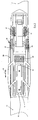
- Fig. 1 shows a cross-country or telemark binding 10, which on the ski deck of a ski 11, in particular a mounted on this mounting plate 12 (see Fig. 3 ) longitudinally displaceable (see double arrow 13 in Fig. 1 ) and latched by means of a locking device 14 in a plurality of sliding positions. It is in the illustrated binding to such, as described in the German patent application 10 2004 018 296.5 the applicant is described.
- This binding is designed for shoes, the soles of which each have at the distance from the front sole end a sole-side engagement element, which with a complementary binding-side engagement element 15 (see Fig. 2 ) cooperates in such a way that the shoe heel 3 can be raised.
- a protrusion is formed on the sole side, which can be brought into contact with a binding-side stop 16 such that the shoe is held in engagement with the binding-side engagement element 15 and at the same time a rocking movement about an imaginary transverse axis behind can perform the stop 16.
- the sole-side engagement element is a transverse axis arranged within a sole recess, as is already known for cross-country skiing or telemark ski boots.
- the binding-side engaging element 15 in the present case comprises an engagement hook 19.
- the binding-side engagement element 15 is longitudinally displaceable and movable by means of an actuating device (actuating lever 20 from a shoe release or entry position into a closed position and vice versa.)
- the shoe is connected by a front end associated with the front sole end Flexor 21 on the one hand and held in the metatarsophalangeal zone, in particular in front of the same arranged rear flexor on the other hand in balanced contact with the ski or ski, wherein in the final phase of lifting the shoe heel lifting the same in addition takes place against the action of the front flexor 21 while in the initial phase of lifting the heel, initially only the rear flexor 22 and then both flexors 21, 22 are effective, especially before the return spring 17 becomes effective.
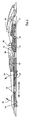
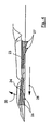
- the locking device 14 is subdivided into a first latching unit 23, which is effective only to the front, and a second latching unit 24, which acts only to the rear, such that when the latching unit 23, which acts only forward, releases the binding only forward (arrow 25 in FIG Fig. 5 ) and when unlocking the only effective rear locking unit 24, the binding only to the rear (arrow 26 in Fig. 4 ) is displaceable.
- the locking units 23, 24 each comprise a binding side elastically biased locking element in the form of punched out of a binding plate tabs, on the underside locking teeth 27, 28 are formed, and a ski or montageplatten general formed locking element with the locking teeth 27, 28 receiving, in particular complementary notches 30, 31 (see Fig. 3 ).
- the binding-side locking elements are - as already mentioned - integral components of the binding, here the binding associated with the binding plate 29. They are stamped out of the binding plate tabs and accordingly flexurally elastic - - binding plate formed.
- the tab of the front detent unit 23 is bounded by a U-punching 32, which is open to the rear in plan view, and the tab associated with the rear detent unit 24 is bounded by a U-punching 33 which is open towards the front. Like that Fig. 2 .
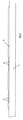
- the mounting plate 12 may be made of plastic or light metal, in particular aluminum. Preferably, however, it consists of plastic and is permanently bonded to the ski deck, whereby the ski body is least affected.
- the mounting plate 12 preferably has a bending behavior such as the upper flange of the ski body 11.
Landscapes
- Footwear And Its Accessory, Manufacturing Method And Apparatuses (AREA)
- Fittings On The Vehicle Exterior For Carrying Loads, And Devices For Holding Or Mounting Articles (AREA)
- Surgical Instruments (AREA)
- Insertion Pins And Rivets (AREA)
- Pharmaceuticals Containing Other Organic And Inorganic Compounds (AREA)
- Transition And Organic Metals Composition Catalysts For Addition Polymerization (AREA)
- Gas Separation By Absorption (AREA)
Description
- Die vorliegende Erfindung betrifft eine Langlauf- oder Telemarkbindung, die auf der Skideckfläche, insbesondere einer auf dieser montierten Montageplatte längsverschieblich gelagert und mittels einer Rastvorrichtung in mehreren Schiebepositionen verrastbar ist.
- Insbesondere im Alpinskibereich gibt es die verschiedensten Ausführungen für eine Einstellung von Vorder- und/oder Hinterbacken in Längsrichtung des Ski, um die aus Vorderbacken und Hinterbacken bestehende Gesamteinheit an einen Skischuh vorbestimmter Länge anzupassen und die Intensität der Kraft einzustellen, mit welcher die Sohle des Schuhs zwischen den beiden Backen festgeklemmt wird. Es wird diesbezüglich beispielhaft auf die
DE 39 24 939 A1 verwiesen, some auf dieDE- A-1929885 . -
WO 88/04563 - Ausgehend von diesem Stand der Technik liegt der vorliegenden Erfindung die Aufgabe zugrunde, für eine Langlauf oder Telemarkbindung eine entsprechende Verstelleinrichtung zu schaffen, die einfach in der Herstellung und vor allem auch einfach in der Handhabung ist, ohne dass die Funktionssicherheit der Bindung verloren geht.
- Diese Aufgabe wird erfindungsgemäß durch eine Konstruktion gemäß dem Kennzeichen des Anspruches 1 gelöst, wobei bevorzugte konstruktive Details in den Unteransprüchen beschrieben sind.
- Dementsprechend umfasst die erfindungsgemäße Bindung eine Rastvorrichtung, die in eine erste, nur nach vorne und eine zweite, nur nach hinten wirksame Rasteinheit unterteilt ist dergestalt, dass bei Entrastung der nur nach vorne wirksamen Rasteinheit die Bindung nur nach vorne und bei Entrastung der nur nach hinten wirksamen Rasteinheit die Bindung nur nach hinten verschiebbar ist. Auf diese Weise wird für den Benutzer sichergestellt, dass er bei Entrastung einer der beiden Rasteinheiten die Bindung auch nur in die entsprechende Richtung verschieben kann, d.h. entweder nur nach vorne oder nur nach hinten. Die in Gegenrichtung wirksame Rasteinheit stört die Verschiebung in die freigegebene Richtung nicht. Zum Zurückschieben der Bindung in die ursprüngliche Stellung oder eine Zwischenstellung ist es erforderlich, die jeweils in die Entgegenrichtung wirksame Rasteinheit zu entriegeln.
- Da die Rasteinheit vorzugsweise Rastzähne einerseits und komplementäre Rastkerben andererseits umfasst, ist erfindungsgemäß eine schrittweise Verstellung der Bindung entweder nach vorne oder nach hinten möglich, wobei die Länge der Einzelschritte von der vorgenannten Verzahnung abhängt.
- Eine besonders einfache Ausführungsform der erfindungsgemäßen Bindung ist dadurch gekennzeichnet, dass die bindungsseitigen Rastelemente integrale Bestandteile der Bindung, insbesondere des Bindungsgehäuses oder einer zugeordneten Bindungsplatte sind. Vorteilhafterweise sind die Rastelemente als biegeelastisch angelenkte oder angeformte Laschen ausgebildet. Zur Umsetzung dieser Konstruktion werden die Rastelemente als integraler Teil einer Bindungsplatte aus dieser herausgestanzt. Die nach vorne wirksame Rastlasche wird durch eine nach hinten offene U-Stanzlinie und die nach hinten wirksame Rastlasche durch eine nach vorne offene U-Stanzlinie begrenzt. Zur Entrastung ist es lediglich erforderlich, entweder unter die vordere oder unter die hintere Rastlasche mit einem Schraubenzieher od. dgl. einzugreifen, um die Rastlasche anzuheben. Dadurch wird die Verrastung zwischen den an der Unterseite der Rastlaschen angeordneten Rastzähnen einerseits und den ski- bzw. montageplattenseitigen Rastkerben andererseits aufgehoben.
- Um den erfindungsgemäßen Zweck der Wirksamkeit der Rasteinheiten nur nach vorne bzw. nur nach hinten in einfacher konstruktiver Weise zu erreichen, sind an den Unterseiten der vorerwähnten Rastlaschen jeweils wenigstens ein Schrägzahn, insbesondere ein Schrägzahnprofil ausgebildet, wobei die vordere Flanke des oder der Zähne des nur nach vorne wirksamen Rastelements sich im wesentlichen senkrecht erstreckt, während die Situation bei dem oder den Zähnen des nur nach hinten wirksamen Rastelements genau umgekehrt ist. Die jeweils andere Flanke erstreckt sich vorzugsweise flach schräg nach hinten bzw. nach vorne, je nachdem, ob es sich um die Zähne des nur nach vorne wirksamen Rastelements oder des nur nach hinten wirksamen Rastelements handelt.
- Vorteilhaft in Verbindung mit der vorgenannten Technik ist noch eine Montageplatte die sehr dünn bzw. nahezu folienartig ausgebildet ist. Vorzugsweise ist die Montageplatte durch Spritzguß hergestellt. Grundsätzlich ist es jedoch auch denkbar, die Montageplatte durch Prägung aus einer flachen Folie herzustellen, wobei die Montageplatte primär aus Kunststoff besteht, z.B. Acrylnitril-Butadien-Styrol-Copolymer (ABS). Dieser Kunststoff kann bei Bedarf durch Kohlenstofffasern verstärkt sein.
- Desweiteren ist es vorteilhaft, die Montageplatte im wesentlichen vollflächig mit der Skideckfläche zu verkleben oder zu verschweißen. Damit verhält sich die Montageplatte wie ein integrales Bauteil der Skideckfläche bzw. des die Skideckfläche definierenden Decklaminats. Die Montageplatte stellt also keinen externen Fremdkörper des Ski dar. Darüber hinaus entstehen durch diese Art der Verbindung keine lokalen, insbesondere punktuellen Streß-Stellen, wie sie z.B. Schraubverbindungen darstellen. Dementsprechend ist auch gewährleistet, dass ohne zerstörerischen Einfluß auf die Montageplatte hohe Zugkräfte aufgebracht werden können. Die Kleb- oder Schweißverbindung bildet sich nach Beendigung der Belastung in ihren ursprünglichen Zustand wieder zurück (Hysterese). Die Konstruktion "vergibt" regelrecht Überbelastungen. Anders stellt sich die Situation bei punktuellen Schraubverbindungen dar. Bei übermässigem Zug auf eine Schraubverbindung wird diese gelockert. Eine Rückbildung in den ursprünglichen Befestigungszustand ist nicht gewährleistet. Ergänzend zu den obigen Ausführungen wird bezüglich der Montageplatte auf die
WO 2004/045728 A2 verwiesen. - Nachstehend wird eine bevorzugte Ausführungsform einer erfindungsgemäßen Langlaufoder Telemarkbindung anhand der beigefügten Zeichnungen näher erläutert. Diese zeigt in
- Fig. 1
- eine erfindungsgemäße Bindung in schematischer Draufsicht;
- Fig. 2.
- die Bindung gemäß
Fig. 1 in schematischer Seitenansicht, teilweise geschnitten; - Fig. 3
- einen Teil eines Ski mit auf die Skideckfläche montierter Montageplatte in Seitenansicht;
- Fig. 4
- einen Teil der Bindung unter Darstellung der Entriegelung einer hinteren Rasteinheit in Seitenansicht, teilweise im Längsschnitt und
- Fig. 5
- einen Teil der Bindung unter Darstellung der Entriegelung einer vorderen Rasteinheit in Seitenansicht, teilweise im Längsschnitt;
-
Fig. 1 zeigt eine Langlauf- oder Telemarkbindung 10, die auf der Skideckfläche eines Ski 11, insbesondere einer auf dieser montierten Montageplatte 12 (sieheFig. 3 ) längsverschieblich (siehe Doppelpfeil 13 inFig. 1 ) gelagert und mittels einer Rastvorrichtung 14 in mehreren Schiebepositionen verrastbar ist. Es handelt sich bei der dargestellten Bindung um eine solche, wie sie in der deutschen Patentanmeldung10 2004 018 296.5 der Anmelderin beschrieben ist. Diese Bindung ist für Schuhe konzipiert, deren Sohlen jeweils im Abstand vom vorderen Sohlenende ein sohlenseitiges Eingriffselement aufweisen, welches mit einem komplementären bindungsseitigen Eingriffselement 15 (sieheFig. 2 ) zusammenwirkt derart, dass der Schuhabsatz 3 anhebbar ist. Zwischen dem sohlenseitigen Eingriffselement und dem vorderen Sohlenende des zugeordneten Schuhs ist sohlenseitig ein Vorsprung ausgebildet, der in Anlage an einem bindungsseitigen Anschlag 16 bringbar ist derart, dass der Schuh mit dem bindungsseitigen Eingriffselement 15 in Eingriff gehalten ist und gleichzeitig eine Wippbewegung um eine imaginäre Querachse hinter dem Anschlag 16 ausführen kann. Das bindungsseitige Eingriffselement 15 und damit ein daran angeschlossener Schuh ist gegen die Wirkung eines elastischen Elements, insbesondere einer Schraubendruckfeder 17 (sieheFig. 2 ) um eine sich quer zur Schuh- bzw. Bindungslängsrichtung erstreckende Horizontalachse 18 nach oben verschwenkbar. Das sohlenseitige Eingriffselement ist eine sich innerhalb einer Sohlenausnehmung angeordnete Querachse, wie sie für Langlaufoder Telemark-Skischuhe bereits bekannt ist. Das bindungsseitige Eingriffselement 15 umfaßt im vorliegenden Fall einen Eingriffshaken 19. Das bindungsseitige Eingriffselement 15 ist längsverschieblich gelagert und mittels einer Betätigungseinrichtung (Betätigungshebel 20 aus einer Schuhfreigabe- bzw. Einstiegsstellung in eine Schließstellung und umgekehrt bewegbar. Der Schuh ist durch einen dem vorderen Sohlenende zugeordneten vorderen Flexor 21 einerseits und durch einen im Bereich der metatarsophalangialen Zone, insbesondere vor derselben angeordneten hinteren Flexor andererseits in ausbalanciertem Kontakt mit der Bindung bzw. Ski gehalten, wobei in der Endphase des Anhebens des Schuhabsatzes das Anheben desselben zusätzlich gegen die Wirkung des vorderen Flexors 21 erfolgt, während in der Anfangsphase des Anhebens des Schuhabsatzes zunächst nur der hintere Flexor 22 und dann beide Flexoren 21, 22 wirksam sind, insbesondere bevor die Rückstellfeder 17 wirksam wird. - Die Rastvorrichtung 14 ist in eine erste, nur nach vorne wirksame Rasteinheit 23 und eine zweite, nur nach hinten wirksame Rasteinheit 24 unterteilt dergestalt, dass bei Entriegelung der nur nach vorne wirksamen Rasteinheit 23 die Bindung nur nach vorne (Pfeil 25 in
Fig. 5 ) und bei Entriegelung der nur nach hinten wirksamen Rasteinheit 24 die Bindung nur nach hinten (Pfeil 26 inFig. 4 ) verschiebbar ist. Die Rasteinheiten 23, 24 umfassen jeweils ein bindungsseitig elastisch vorgespanntes Rastelement in Form von aus einer Bindungsplatte ausgestanzten Laschen, an deren Unterseite Rastzähne 27, 28 ausgebildet sind, und ein ski- oder montageplattenseitig ausgebildetes Rastelement mit die Rastzähne 27, 28 aufnehmenden, insbesondere komplementären Kerben 30, 31 (sieheFig. 3 ). Die bindungsseitigen Rastelemente sind - wie bereits erwähnt - integrale Bestandteile der Bindung, hier der der Bindung zugeordneten Bindungsplatte 29. Sie sind aus der Bindungsplatte ausgestanzte Laschen und dementsprechend biegeelastisch an der- - Bindungsplatte angeformt. Die Lasche der vorderen Rasteinheit 23 wird durch eine in Draufsicht nach hinten offene U-Stanzung 32, und die der hinteren Rasteinheit 24 zugeordnete Lasche durch eine nach vorne offene U-Stanzung 33 begrenzt. Wie denFig. 2 ,4 und5 sehr gut entnommen werden kann, sind an der Unterseite der Rastlaschen Schrägzahnprofile ausgebildet, wobei die vordere Flanke der Zähne 27 des nur nach vorne wirksamen Rastelements sich im wesentlichen senkrecht erstreckt, während bei den dem nur nach hinten wirksamen Rastelement zugeordneten Zähnen 28 die hintere Flanke sich etwa senkrecht erstreckt. In entsprechender Weise sind die komplementären Kerben 30, 31 an der Oberseite der Montageplatte 12 ausgebildet. Die jeweils entgegengesetzten Flanken sind jeweils flach geneigt, so dass sich beim Anheben z.B. der vorderen Rastlasche entsprechend Pfeil 34 inFig. 5 die entsprechende Verrastung aufgelöst wird, so dass die Bindung 10 nach vorne verschoben werden kann. Bei Anheben der hinteren Rastlasche in Richtung des Pfeils 35 inFig. 4 wird die hintere Verrastung aufgehoben und die Bindung 10 läßt sich nach hinten verschieben. Diese Verschiebung in Richtung der Pfeile 25 bzw. 26 wird durch die flach geneigten Flanken der hinteren Rastzähne 28 bzw. vorderen Rastzähne 27 nicht behindert. - Die Montageplatte 12 kann aus Kunststoff oder Leichtmetall, insbesondere Aluminium bestehen. Vorzugsweise besteht sie jedoch aus Kunststoff und ist auf die Skideckfläche dauerhaft aufgeklebt, wodurch der Skikörper am wenigsten beeinträchtigt wird. Die Montageplatte 12 weist vorzugsweise ein Biegeverhalten auf wie der Obergurt des Skikörpers 11.
-
- 10
- Bindung
- 11
- Ski
- 12
- Montageplatte
- 13
- Doppelpfeil
- 14
- Rastvorrichtung
- 15
- Eingriffselement
- 16
- bindungsseitiger Anschlag
- 17
- Schraubendruckfeder(n)
- 18
- Schwenkachse
- 19
- Eingriffshaken
- 20
- Betätigungshebel
- 21
- vorderer Flexor
- 22
- hinterer Flexor
- 23
- erste Rasteinheit
- 24
- zweite Rasteinheit
- 25
- Pfeil
- 26
- Pfeil
- 27
- Rastzähne
- 28
- Rastzähne
- 29
- Bindungsplatte
- 30
- Kerben
- 31
- Kerben
- 32
- U-Stanzung
- 33
- U-Stanzung
- 34
- Pfeil
- 35
- Pfeil
Claims (6)
- Langlauf- oder Telemarkbindung (10), die auf einer auf einer Skideckfläche montierten Montageplatte (12) längsverschieblich (13) gelagert und mittels einer Rastvorrichtung (14) in mehreren Schiebepositionen verrastbar ist, wobei diese Rastvorrichtung (14) in eine erste (23) und in eine zweite (24) Rasteinheit unterteilt ist, dadurch gekennzeichnet daß die erste (23) Rasteinheit nur nach vorne und die zweite (24) Rasteinheit nur nach hinten wirksom sind dergestalt, daß bei Entriegelung der nur nach vorne wirksamen Rasteinheit (23) die Bindung nur nach vorne (25) und bei Entriegelung der nur nach hinten wirksamen Rasteinheit (24) die Bindung nur nach hinten (26) verschiebbar ist.
- Bindung nach Anspruch 1,
dadurch gekennzeichnet, dass
die Rasteinheiten (23, 24) jeweils bindungsseitig ein elastisch vorgespanntes Rastelement mit Rastzähnen (27, 28), und ski- oder montageplattenseitig ein Gegen-Rastelement mit die Rastzähne (27, 28) aufnehmenden Kerben (30, 31) umfassen. - Bindung nach Anspruch 2,
dadurch gekennzeichnet, dass
die bindungsseitigen Rastelemente integrale Bestandteile der Bindung, insbesondere einer zugeordneten Bindungsplatte (29) sind. - Bindung nach Anspruch 2 oder 3,
dadurch gekennzeichnet, dass
die bindungsseitigen Rastelemente jeweils biegeelastisch angelenkte oder angeformte Laschen sind, an deren Unterseiten jeweils wenigstens ein Schrägzahn, insbesondere ein Schrägzahnprofil ausgebildet ist, wobei die vordere Flanke des oder der Zähne (27) des nur nach vorne wirksamen Rastelements sich im wesentlichen senkrecht erstreckt, während die Situation bei dem oder den Zähnen (28) des nur nach hinten wirksamen Rastelements genau umgekehrt ist. - Bindung, insbesondere nach einem der Ansprüche 1-3,
dadurch gekennzeichnet, dass
die Rastvorrichtung wenigstens ein Rastelement aufweist, welches integraler Bestandteil der Rastvorrichtung, insbesondere integraler Bestandteil der Bindung oder eines dieser zugeordneten Bindungsplatte (29) ist. - Bindung nach Anspruch 5,
dadurch gekennzeichnet, dass
das wenigstens eine Rastelement als einstückig mit der Bindung, insbesondere einer dieser zugeordneten Bindungs- oder Fersenplatte verbundene Lasche mit einem Rastvorsprung oder einer Rastausnehmung für komplementäre Rastelemente an der Montageplatte (12) ausgebildet ist.
Applications Claiming Priority (2)
| Application Number | Priority Date | Filing Date | Title |
|---|---|---|---|
| DE102004024881A DE102004024881A1 (de) | 2004-05-19 | 2004-05-19 | Langlauf- oder Telemarkbindung |
| PCT/IB2005/000116 WO2005113081A1 (de) | 2004-05-19 | 2005-01-13 | Langlauf- oder telemarkbindung |
Publications (2)
| Publication Number | Publication Date |
|---|---|
| EP1748827A1 EP1748827A1 (de) | 2007-02-07 |
| EP1748827B1 true EP1748827B1 (de) | 2008-08-20 |
Family
ID=34673261
Family Applications (1)
| Application Number | Title | Priority Date | Filing Date |
|---|---|---|---|
| EP05702278A Expired - Lifetime EP1748827B1 (de) | 2004-05-19 | 2005-01-13 | Langlauf- oder telemarkbindung |
Country Status (8)
| Country | Link |
|---|---|
| US (1) | US7887080B2 (de) |
| EP (1) | EP1748827B1 (de) |
| CN (1) | CN1956753B (de) |
| AT (1) | ATE405333T1 (de) |
| DE (2) | DE102004024881A1 (de) |
| NO (1) | NO331473B1 (de) |
| RU (1) | RU2352376C2 (de) |
| WO (1) | WO2005113081A1 (de) |
Cited By (1)
| Publication number | Priority date | Publication date | Assignee | Title |
|---|---|---|---|---|
| EP3202470A1 (de) | 2014-03-19 | 2017-08-09 | Madshus AS | Mechanismus zur längsverriegelung einer skibindung auf einer montageplatte |
Families Citing this family (25)
| Publication number | Priority date | Publication date | Assignee | Title |
|---|---|---|---|---|
| DE102004024881A1 (de) | 2004-05-19 | 2005-07-14 | Rottefella As | Langlauf- oder Telemarkbindung |
| FR2890317B1 (fr) | 2005-09-08 | 2007-11-23 | Salomon Sa | Dispositif de fixation a ancrage perfectionne |
| DE102005049267A1 (de) * | 2005-10-14 | 2006-05-04 | Rottefella As | Langlauf- oder Telemarkbindung |
| FR2894836B1 (fr) | 2005-12-16 | 2008-02-22 | Salomon Sa | Ensemble ski de fond et dispositif de fixation de ski de fond |
| FR2899121B1 (fr) | 2006-03-29 | 2008-07-04 | Salomon Sa | Ensemble ski de fond et dispositif de fixation de ski de fond |
| FR2901486A1 (fr) * | 2006-05-24 | 2007-11-30 | Salomon Sa | Ensemble comprenant une planche de glisse et un dispositif de retenue d'un article chaussant sur la planche |
| FR2927544B1 (fr) * | 2008-02-15 | 2010-08-13 | Salomon Sa | Dispositif d'accueil d'une chaussure sur un engin de sport |
| EP2135645B1 (de) * | 2008-06-19 | 2015-10-07 | Rottefella AS | Zerlegbare Skibindung |
| EP2204223A1 (de) * | 2009-01-05 | 2010-07-07 | Rottefella AS | Ski und Skibindungsgehäuse |
| CN102470271B (zh) * | 2009-07-17 | 2014-12-03 | 罗特费尔拉公司 | 带有紧固夹持部的折屈件 |
| NO20101288A1 (no) | 2010-09-15 | 2012-02-27 | Rottefella As | Sammenstilling for tilkobling av en støvel til en ski, samt mellomstykke for bruk i nevnte sammenstilling |
| WO2012045329A1 (en) | 2010-10-04 | 2012-04-12 | Madshus As | Ski binding |
| EP2624924B1 (de) | 2010-10-04 | 2019-09-18 | Madshus A/S | Skibindung |
| US9149711B1 (en) | 2014-11-14 | 2015-10-06 | The Burton Corporation | Snowboard binding and boot |
| US9220970B1 (en) | 2014-11-14 | 2015-12-29 | The Burton Corporation | Snowboard binding and boot |
| EP3218073B1 (de) | 2014-11-14 | 2021-05-19 | The Burton Corporation | Snowboard-bindung |
| FI20175430A (fi) * | 2014-11-27 | 2017-05-12 | Stanislav Viktorovich Mozgovoi | Suksi lisälaitteella suksisiteen asentamista varten |
| USD820933S1 (en) * | 2016-05-04 | 2018-06-19 | Salomon S.A.S. | Ski binding |
| USD820932S1 (en) * | 2016-05-04 | 2018-06-19 | Salomon S.A.S. | Ski binding |
| EP3260177A1 (de) * | 2016-06-23 | 2017-12-27 | Fischer Sports GmbH | Skibindung |
| NO342933B1 (no) * | 2017-05-30 | 2018-09-03 | Rottefella As | Festemekanisme for et låseorgan som skal festes til en monteringsplate på en langrennsski |
| FR3076737B1 (fr) * | 2018-01-12 | 2020-01-03 | Salomon Sas | Dispositif de retenue d'une chaussure sur une planche de glisse et engin de glisse comprenant un tel dispositif |
| RU182954U1 (ru) * | 2018-04-21 | 2018-09-06 | Станислав Викторович Мозговой | Съемный флексор с продольной фиксацией для лыжного крепления |
| FR3100136B1 (fr) | 2019-08-30 | 2021-09-17 | Salomon Sas | Dispositif de retenue pour planche de glisse |
| FR3103391B1 (fr) * | 2019-11-22 | 2021-11-19 | Rossignol Sa | Dispositif de fixation pour planche de glisse |
Family Cites Families (98)
| Publication number | Priority date | Publication date | Assignee | Title |
|---|---|---|---|---|
| DE327066C (de) | 1920-10-06 | Carl William Egeling | Vorrichtung zum Drehen von Raedern mit glatten Kraenzen mittels Reibrollen | |
| DE609675C (de) * | 1932-11-16 | 1935-02-21 | Adolf Attenhofer | Skibindung |
| US2094667A (en) * | 1936-06-22 | 1937-10-05 | Adam H Schwandt | Separable ski binder |
| US3137014A (en) * | 1962-03-02 | 1964-06-16 | Glenn Engineering Company | Water ski binder |
| DE1929885A1 (de) * | 1969-06-12 | 1970-12-23 | Paul Unger | Skibindung,insbesondere Skibobbindung |
| SU384524A1 (ru) * | 1971-08-04 | 1973-05-29 | УСТРОЙСТВО дл КРЕПЛЕНИЯ ГОРНОЛЫЖНОГО БОТИНКА К ЛЫЖЕ | |
| AT327066B (de) * | 1973-07-04 | 1976-01-12 | Smolka & Co Wiener Metall | Verstelleinrichtung an skibindungen |
| CH557154A (de) | 1974-01-03 | 1974-12-31 | Bata Schuhe Ag | Schuhsohle, insbesondere fuer langlaufskischuh. |
| FR139862A (de) * | 1974-03-25 | |||
| DE2418577A1 (de) | 1974-04-17 | 1975-10-30 | Huber Hans Peter | Schisicherheitsbindung mit einem als platte ausgebildeten zwischenglied |
| AT354306B (de) | 1976-01-22 | 1980-01-10 | Dynafit Gmbh | Versteifungseinlage fuer fussbekleidung |
| DE2645007A1 (de) | 1976-03-27 | 1978-04-13 | Continental Gummi Werke Ag | Skistiefel |
| AT352599B (de) * | 1977-02-23 | 1979-09-25 | Tyrolia Freizeitgeraete | Sicherheitsskibindung |
| DE2714853A1 (de) | 1977-04-02 | 1978-10-12 | Manfred Poschmann | Tourenvorrichtung fuer ski-sicherheitsbindungen |
| DE2728747C2 (de) | 1977-06-25 | 1986-06-19 | Fa. Carl Freudenberg, 6940 Weinheim | Vorrichtung zur wahlweisen Anpassung einer Abfahrtsschibindung an den Tourenlauf |
| US4186500A (en) * | 1978-04-27 | 1980-02-05 | Tyrol Shoe Co. Ltd. | Molded cross-country ski boot |
| DE2846914C2 (de) * | 1978-10-27 | 1981-03-12 | Geze Gmbh, 7250 Leonberg | Sicherheits-Plattenskibindung |
| AT363023B (de) * | 1978-12-04 | 1981-07-10 | Linecker Josef | Langlaufbindung mit zugehoerigem schischuh |
| IT1166283B (it) | 1979-11-20 | 1987-04-29 | Gianni Bonsembiante | Suola, rinforzo ad irrigidimento trasversale ed elasticita' longitudinale per calzature da fondo per sci |
| US4322090A (en) * | 1980-02-13 | 1982-03-30 | Loughney Charles E | Ski mountaineering binding |
| AT376572B (de) * | 1980-11-14 | 1984-12-10 | Tyrolia Freizeitgeraete | Verstellvorrichtung |
| DE3113942A1 (de) | 1981-04-07 | 1982-10-28 | Sportartikelfabrik Karl Uhl Gmbh, 7460 Balingen | Langlauf-skischuh mit einer laufsohle aus kunststoffmaterial |
| DE3201319A1 (de) | 1982-01-18 | 1983-07-28 | ess GmbH Skibindungen, 8978 Burgberg | Skibindungsbacken |
| DE3222132A1 (de) | 1982-06-11 | 1983-12-15 | Hallbach, Hans-Joachim, 8000 München | Sicherheitsskibindung |
| IT1169103B (it) * | 1983-02-21 | 1987-05-27 | Antonio Faulin | Suola per scarpa da sci |
| FR2556188B1 (fr) | 1983-12-09 | 1986-05-16 | Salomon Sa | Procede de fabrication d'une chaussure de sport et chaussure obtenue par ce procede |
| FR2569119B1 (fr) | 1984-08-17 | 1986-11-21 | Salomon Sa | Procede pour relier un element sur un ski, et notamment pieces d'appui fixables par ce procede, procede de preparation du ski en vue de cette fixation, gabarit pour cette preparation et ski ainsi prepare |
| DE3530095A1 (de) * | 1985-08-22 | 1987-02-26 | Pittl K Metallwerk | Langlaufskibindung |
| US5025573A (en) | 1986-06-04 | 1991-06-25 | Comfort Products, Inc. | Multi-density shoe sole |
| AT386537B (de) * | 1986-12-18 | 1988-09-12 | Tyrolia Freizeitgeraete | Verstelleinrichtung fuer skibindungen |
| NO871938L (no) * | 1986-12-19 | 1988-04-19 | Witco As | Anordning ved en skibinding. |
| US4772041A (en) * | 1987-02-20 | 1988-09-20 | Klosterman James E | Simplified adjustable ski binding structure |
| FR2623094B1 (fr) | 1987-11-18 | 1993-06-11 | Salomon Sa | Dispositif de guidage lateral d'une chaussure de ski fixee, a son extremite avant, sur un ski tel qu'un ski de fond |
| US5356169A (en) * | 1987-11-18 | 1994-10-18 | Salomon S.A. | Flexible and length adjustable lateral guide apparatus for a cross-country ski shoe |
| FR2635013B1 (fr) * | 1988-08-03 | 1990-10-26 | Salomon Sa | Dispositif de fixation d'une chaussure sur un ski de fond |
| US4887833A (en) * | 1988-09-26 | 1989-12-19 | Bailey Mark R | Touring ski binding |
| FR2638653B1 (fr) * | 1988-11-07 | 1991-01-25 | Salomon Sa | Fixation de securite pour ski |
| FR2638654B1 (fr) * | 1988-11-08 | 1991-02-08 | Salomon Sa | Fixation de securite pour ski |
| AT396068B (de) * | 1990-03-30 | 1993-05-25 | Tyrolia Freizeitgeraete | Skibindung fuer einen langlauf- oder tourenski |
| ATE115876T1 (de) * | 1990-04-05 | 1995-01-15 | Head Sport Ag | Ski. |
| CH684313A5 (de) * | 1990-08-07 | 1994-08-31 | Varpat Patentverwertung | Plattenförmige Dämpfungsvorrichtung für eine Schibindung. |
| AT402900B (de) * | 1990-12-21 | 1997-09-25 | Varpat Patentverwertung | Kupplungsvorrichtung zwischen schi und schischuh mit einer längenverstellvorrichtung |
| FR2682011B1 (fr) | 1991-10-03 | 1995-05-05 | Salomon Sa | Chaussure de sport notamment de ski de fond comportant des moyens de rigidification en torsion et d'assouplissement en flexion. |
| US5344179A (en) * | 1991-11-28 | 1994-09-06 | Fritschi Ag. Apparatebau | Adjustable length binding system for snowboards having independently variable heel and toe spans |
| USD345454S (en) * | 1991-12-19 | 1994-03-29 | Rottefella As | Rubber sole for cross-country ski shoe |
| FR2689775B1 (fr) * | 1992-04-10 | 1994-07-08 | Salomon Sa | Dispositif interface entre un ski et des elements de fixation, notamment de fixation alpine. |
| AT404901B (de) * | 1992-08-19 | 1999-03-25 | Varpat Patentverwertung | Anzeigevorrichtung für eine kupplungsvorrichtung zwischen einem schuh und einem sportgerät, insbesondere schibindung |
| DE9320530U1 (de) | 1993-09-16 | 1994-10-13 | Rottefella As, Klokkarstua | Langlauf- oder Tourenskibindung für Langlaufskischuhe |
| US6374517B2 (en) * | 1994-04-29 | 2002-04-23 | Salomon S.A. | Sole for a sport boot and a sport boot including such sole |
| FR2739788B1 (fr) * | 1995-10-16 | 1997-12-12 | Salomon Sa | Ensemble de fixation d'une chaussure a un organe de glisse |
| FR2719230B1 (fr) * | 1994-04-29 | 1996-06-28 | Salomon Sa | Dispositif de fixation d'une chaussure à un ski de fond. |
| FR2719229B1 (fr) * | 1994-04-29 | 1996-06-28 | Salomon Sa | Dispositif de fixation d'une chaussure à un ski de fond. |
| JPH08506986A (ja) * | 1994-05-09 | 1996-07-30 | ハーテーエム シュポルト− ウント フライツァイトゲレーテ アクチエンゲゼルシャフト | 長手方向調節するための装置 |
| US5484149A (en) * | 1994-06-10 | 1996-01-16 | Yuh Jou Co., Ltd. | Adjustable roller skate structure |
| EP0694320B1 (de) * | 1994-07-22 | 2000-06-14 | Marker Deutschland GmbH | Vorrichtung auf einem Ski |
| DE59602385D1 (de) * | 1995-02-02 | 1999-08-12 | Rottefella As | Kombination einer skibindung und eines daran angepassten schuhs |
| DE19517791A1 (de) | 1995-05-15 | 1996-11-21 | Rottefella As | Kombination einer Skibindung und eines daran angepaßten Schuhs |
| FR2734492B1 (fr) * | 1995-05-22 | 1997-06-27 | Rossignol Sa | Planche de glisse sur neige comportant un dispositif pour le montage d'une fixation d'une chaussure |
| FR2738157B1 (fr) * | 1995-09-06 | 1997-10-17 | Salomon Sa | Dispositif de fixation automatique |
| US5765854A (en) * | 1995-10-23 | 1998-06-16 | Moore; Lonny J. | Binding mounting system |
| FR2741543A1 (fr) | 1995-11-27 | 1997-05-30 | Bibollet Jean Claude | Fixations pour ski de fond |
| FR2742060B1 (fr) | 1995-12-08 | 1998-01-09 | Salomon Sa | Dispositif de fixation d'une chaussure a un article de sport |
| FR2743989B1 (fr) * | 1996-01-30 | 1998-03-20 | Salomon Sa | Semelle pour chaussure de sport |
| EP0820790A3 (de) | 1996-07-23 | 1998-12-30 | Emery S.A. | Sicherheitsbindung für Tourenskis |
| EP0878218B1 (de) | 1997-05-15 | 2003-08-13 | Rottefella A/S | Schuhabroll- und -stützelement als Teil einer Skibindung |
| EP0908204A3 (de) | 1997-10-10 | 1999-04-28 | Rottefella A/S | Touren-, Telemark- oder Langlauf-Skibindung |
| FR2771941B1 (fr) * | 1997-12-10 | 2000-01-28 | Rossignol Sa | Fixation de ski comportant deux elements de fixation deplacables sur une glissiere |
| FR2770097B3 (fr) * | 1997-10-29 | 2000-01-07 | Salomon Sa | Semelle de chaussure de sport |
| US6315318B1 (en) * | 1998-01-14 | 2001-11-13 | Caron Alpine Technologies, Inc. | Boot binding system |
| DE19809729A1 (de) * | 1998-03-06 | 1999-09-09 | Rottefella As | Langlauf- oder Tourenskibindung |
| EP0951926B1 (de) | 1998-04-24 | 2004-12-01 | Rottefella A/S | Touren-, Telemark- oder Langlauf-Skibindung |
| FR2782652B1 (fr) * | 1998-09-02 | 2000-10-06 | Salomon Sa | Dispositif de fixation d'une chaussure a un article de sport |
| CH693129A5 (de) * | 1998-11-16 | 2003-03-14 | Look Fixations Sa | Sicherheitsskibindung. |
| EP1146934B1 (de) * | 1999-08-06 | 2002-05-08 | Marker Deutschland GmbH | Längenverstelleinrichtung einer sicherheitsskibindung |
| AT408725B (de) * | 1999-09-21 | 2002-02-25 | Atomic Austria Gmbh | Bindungshaltesystem zur schnellmontage eines vorder- und fersenbackens einer schibindung |
| IT1311885B1 (it) * | 1999-12-28 | 2002-03-19 | Benetton Spa | Dispositivo di regolazione,particolarmente della taglia di un pattinocon ruote in linea |
| FR2803178A1 (fr) | 1999-12-31 | 2001-07-06 | Serge Vigny | Ensemble fixation-chaussure pour engin de glisse |
| US7264263B2 (en) * | 2000-03-07 | 2007-09-04 | Rottefella A/S | Ski binding |
| DE20007032U1 (de) | 2000-04-17 | 2000-08-03 | Eckart, Martin, 88171 Weiler-Simmerberg | Telemark-Tourenskibindung |
| SI20723A (sl) | 2000-12-19 | 2002-06-30 | Elan, D.D. | Smučka z vgrajenim sklopom za nastavljivo pritrditev smučarske vezi |
| FR2820335B1 (fr) * | 2001-02-02 | 2003-03-07 | Rossignol Sa | Plaque interface destinee a etre solidarisee a la face superieure d'un ski |
| EP1240925A1 (de) | 2001-03-12 | 2002-09-18 | Andreas Allmann | Führungsschiene und Vorrichtung zum Verbinden einer Bindung für einen Sportschuh mit einem Ski oder Snowboard |
| WO2002089931A1 (de) * | 2001-05-08 | 2002-11-14 | Rottefella As | Skibindung |
| DE10124893A1 (de) | 2001-05-08 | 2002-11-21 | Rottefella As Klokkarstua | Skibindung |
| US6450510B1 (en) * | 2001-10-03 | 2002-09-17 | European Sports Enterprise Co., Ltd. | In-line roller skate having adjustable toe portion |
| DE10200880A1 (de) | 2002-01-11 | 2003-07-24 | Rottefella As Klokkarstua | Sohle für Langlaufski- oder Telemark-Schuh, sowie Schuh mit entsprechender Sohle |
| US6612592B1 (en) * | 2002-04-02 | 2003-09-02 | Mike Soo | Skate with a size-adjustable boot |
| DE10220483A1 (de) * | 2002-05-07 | 2003-11-27 | Marker Deutschland Gmbh | Halterungssystem für vordere und hintere Schuhhalteraggregate einer Bindung für Ski bzw. Skigleitbretter |
| EP1509288B1 (de) | 2002-06-04 | 2006-06-21 | Rottefella AS | Skibindung, insbesondere touren-, telemark- oder langlaufbindung |
| USD488294S1 (en) * | 2002-09-20 | 2004-04-13 | Salomon S.A. | Sole for footwear |
| DE10254471A1 (de) | 2002-11-21 | 2004-06-03 | Madsus A/S | Ski mit Bindungs-Montagehilfe, Verfahren zur Herstellung eines solchen Ski sowie entsprechende Montagehilfe |
| FR2850031B1 (fr) * | 2003-01-21 | 2006-08-11 | Salomon Sa | Fixation a energie deportee |
| DE10319675A1 (de) | 2003-04-17 | 2003-11-27 | Rottefella As Klokkarstua | Skibindung, insbesondere Touren-, Telemark- oder Langlaufbindung |
| FR2856312B1 (fr) * | 2003-06-18 | 2005-08-05 | Salomon Sa | Dispositif de fixation a bras pivotant |
| DE102004018296A1 (de) | 2004-04-15 | 2005-02-10 | Rottefella ASA | Langlauf- oder Telemarkbindung, sowie daran angepaßte Schuhe |
| DE102004023832A1 (de) | 2004-04-22 | 2005-06-30 | Rottefella As | Skibindung, insbesondere Touren-, Telemark- oder Langlaufbindung |
| DE102004024881A1 (de) | 2004-05-19 | 2005-07-14 | Rottefella As | Langlauf- oder Telemarkbindung |
| WO2006072812A1 (de) | 2005-01-10 | 2006-07-13 | Rottefella As | Ski oder dergleichen schneegleitgerät mit bindungs-montagehilfe |
-
2004
- 2004-05-19 DE DE102004024881A patent/DE102004024881A1/de not_active Withdrawn
-
2005
- 2005-01-13 RU RU2006144813/12A patent/RU2352376C2/ru active
- 2005-01-13 US US11/579,249 patent/US7887080B2/en not_active Expired - Fee Related
- 2005-01-13 WO PCT/IB2005/000116 patent/WO2005113081A1/de not_active Ceased
- 2005-01-13 AT AT05702278T patent/ATE405333T1/de active
- 2005-01-13 DE DE502005005124T patent/DE502005005124D1/de not_active Expired - Lifetime
- 2005-01-13 CN CN200580016008.6A patent/CN1956753B/zh not_active Expired - Fee Related
- 2005-01-13 EP EP05702278A patent/EP1748827B1/de not_active Expired - Lifetime
-
2006
- 2006-12-18 NO NO20065837A patent/NO331473B1/no unknown
Cited By (3)
| Publication number | Priority date | Publication date | Assignee | Title |
|---|---|---|---|---|
| EP3202470A1 (de) | 2014-03-19 | 2017-08-09 | Madshus AS | Mechanismus zur längsverriegelung einer skibindung auf einer montageplatte |
| DE202015009508U1 (de) | 2014-03-19 | 2018-01-15 | Madshus As | Mechanismus zum Verriegeln einer Skibindung in der Längsrichtung auf einer Begfestigungsplatte |
| DE202015009512U1 (de) | 2014-03-19 | 2018-02-01 | Madshus As | Mechanismus zum Verriegeln einer Skibindung in der Längsrichtung auf einer Befestigungsplatte |
Also Published As
| Publication number | Publication date |
|---|---|
| DE102004024881A1 (de) | 2005-07-14 |
| ATE405333T1 (de) | 2008-09-15 |
| NO20065837L (no) | 2006-12-18 |
| WO2005113081A1 (de) | 2005-12-01 |
| CN1956753A (zh) | 2007-05-02 |
| CN1956753B (zh) | 2011-02-16 |
| RU2352376C2 (ru) | 2009-04-20 |
| US20080129015A1 (en) | 2008-06-05 |
| RU2006144813A (ru) | 2008-06-27 |
| NO331473B1 (no) | 2012-01-09 |
| EP1748827A1 (de) | 2007-02-07 |
| US7887080B2 (en) | 2011-02-15 |
| DE502005005124D1 (de) | 2008-10-02 |
Similar Documents
| Publication | Publication Date | Title |
|---|---|---|
| EP1748827B1 (de) | Langlauf- oder telemarkbindung | |
| DE102013201725B4 (de) | Fersenhalter mit Verriegelungshebel | |
| DE19623825C1 (de) | Langlauf- oder Tourenskibindung | |
| DE60112208T2 (de) | Verbesserte Kupplung eines Stiefels an ein Snowboard | |
| DE69606372T2 (de) | Längsverstellbare Skibindungsgrundplatte | |
| EP3974039A1 (de) | Bremsanordnung für eine tourenbindung | |
| DE2747626A1 (de) | Skibindung mit einer als fersenbacken oder vorderbacken ausgebildeten skistiefelhalterung | |
| AT404898B (de) | Bindung und schuh für gleitbretter | |
| EP2097142B1 (de) | Skibindung | |
| DE202006019489U1 (de) | Vorrichtung zur Aufnahme eines Fußes oder eines Schuhs auf einem Sportgerät | |
| EP0830185A1 (de) | Anordnung einer langlauf-, insbesondere skating-bindung | |
| EP3453432A1 (de) | Ultraleichter vorderbacken | |
| DE69202327T2 (de) | Zwischenliegendes Stück für die Führungsschiene eines Bindungseinzelteils, insbesondere einer Skibindung. | |
| AT510021B1 (de) | Sohlenauflageplatte und skibindung mit einer sohlenauflageplatte | |
| EP1378274B1 (de) | Anordnung zum Längsverstellen eines Skibindungsteils | |
| DE2401808A1 (de) | Sicherheits-skibindung | |
| EP3714952A1 (de) | Bremsvorrichtung | |
| DE1578818A1 (de) | Sohlenauflageplatte fuer Skibindungen | |
| EP2821114A1 (de) | Sicherheitsskibindungssystem | |
| EP1495786B1 (de) | Montagesystem für eine Skibindung an einem Ski | |
| AT3723U1 (de) | Übergangsvorrichtung zwischen einem ski und haltelementen für einen schuh, um schnell und einfach die longitudinale position der vorderen und hinteren haltelemente auf einem ski einzustellen | |
| DE1961285C3 (de) | Auslösebindung für Skier | |
| EP1645310A1 (de) | Verstellanordnung einer Ski- bzw. Snowboardbindung | |
| EP1790396A2 (de) | Skibindung, insbesondere Telemarkbindung | |
| AT18110U1 (de) | Ausgleichselement und Fersenbacken mit einem Ausgleichselement |
Legal Events
| Date | Code | Title | Description |
|---|---|---|---|
| PUAI | Public reference made under article 153(3) epc to a published international application that has entered the european phase |
Free format text: ORIGINAL CODE: 0009012 |
|
| 17P | Request for examination filed |
Effective date: 20061122 |
|
| AK | Designated contracting states |
Kind code of ref document: A1 Designated state(s): AT BE BG CH CY CZ DE DK EE ES FI FR GB GR HU IE IS IT LI LT LU MC NL PL PT RO SE SI SK TR |
|
| 17Q | First examination report despatched |
Effective date: 20070413 |
|
| DAX | Request for extension of the european patent (deleted) | ||
| GRAP | Despatch of communication of intention to grant a patent |
Free format text: ORIGINAL CODE: EPIDOSNIGR1 |
|
| GRAS | Grant fee paid |
Free format text: ORIGINAL CODE: EPIDOSNIGR3 |
|
| GRAA | (expected) grant |
Free format text: ORIGINAL CODE: 0009210 |
|
| AK | Designated contracting states |
Kind code of ref document: B1 Designated state(s): AT BE BG CH CY CZ DE DK EE ES FI FR GB GR HU IE IS IT LI LT LU MC NL PL PT RO SE SI SK TR |
|
| REG | Reference to a national code |
Ref country code: GB Ref legal event code: FG4D Free format text: NOT ENGLISH |
|
| REG | Reference to a national code |
Ref country code: CH Ref legal event code: EP |
|
| REG | Reference to a national code |
Ref country code: IE Ref legal event code: FG4D Free format text: LANGUAGE OF EP DOCUMENT: GERMAN |
|
| REF | Corresponds to: |
Ref document number: 502005005124 Country of ref document: DE Date of ref document: 20081002 Kind code of ref document: P |
|
| REG | Reference to a national code |
Ref country code: CH Ref legal event code: NV Representative=s name: TROESCH SCHEIDEGGER WERNER AG |
|
| REG | Reference to a national code |
Ref country code: SE Ref legal event code: TRGR |
|
| PG25 | Lapsed in a contracting state [announced via postgrant information from national office to epo] |
Ref country code: NL Free format text: LAPSE BECAUSE OF FAILURE TO SUBMIT A TRANSLATION OF THE DESCRIPTION OR TO PAY THE FEE WITHIN THE PRESCRIBED TIME-LIMIT Effective date: 20080820 Ref country code: LT Free format text: LAPSE BECAUSE OF FAILURE TO SUBMIT A TRANSLATION OF THE DESCRIPTION OR TO PAY THE FEE WITHIN THE PRESCRIBED TIME-LIMIT Effective date: 20080820 Ref country code: IS Free format text: LAPSE BECAUSE OF FAILURE TO SUBMIT A TRANSLATION OF THE DESCRIPTION OR TO PAY THE FEE WITHIN THE PRESCRIBED TIME-LIMIT Effective date: 20081220 |
|
| PG25 | Lapsed in a contracting state [announced via postgrant information from national office to epo] |
Ref country code: SI Free format text: LAPSE BECAUSE OF FAILURE TO SUBMIT A TRANSLATION OF THE DESCRIPTION OR TO PAY THE FEE WITHIN THE PRESCRIBED TIME-LIMIT Effective date: 20080820 Ref country code: ES Free format text: LAPSE BECAUSE OF FAILURE TO SUBMIT A TRANSLATION OF THE DESCRIPTION OR TO PAY THE FEE WITHIN THE PRESCRIBED TIME-LIMIT Effective date: 20081201 |
|
| REG | Reference to a national code |
Ref country code: IE Ref legal event code: FD4D |
|
| PG25 | Lapsed in a contracting state [announced via postgrant information from national office to epo] |
Ref country code: IE Free format text: LAPSE BECAUSE OF FAILURE TO SUBMIT A TRANSLATION OF THE DESCRIPTION OR TO PAY THE FEE WITHIN THE PRESCRIBED TIME-LIMIT Effective date: 20080820 Ref country code: DK Free format text: LAPSE BECAUSE OF FAILURE TO SUBMIT A TRANSLATION OF THE DESCRIPTION OR TO PAY THE FEE WITHIN THE PRESCRIBED TIME-LIMIT Effective date: 20080820 Ref country code: BG Free format text: LAPSE BECAUSE OF FAILURE TO SUBMIT A TRANSLATION OF THE DESCRIPTION OR TO PAY THE FEE WITHIN THE PRESCRIBED TIME-LIMIT Effective date: 20081120 |
|
| PG25 | Lapsed in a contracting state [announced via postgrant information from national office to epo] |
Ref country code: SK Free format text: LAPSE BECAUSE OF FAILURE TO SUBMIT A TRANSLATION OF THE DESCRIPTION OR TO PAY THE FEE WITHIN THE PRESCRIBED TIME-LIMIT Effective date: 20080820 Ref country code: RO Free format text: LAPSE BECAUSE OF FAILURE TO SUBMIT A TRANSLATION OF THE DESCRIPTION OR TO PAY THE FEE WITHIN THE PRESCRIBED TIME-LIMIT Effective date: 20080820 Ref country code: PT Free format text: LAPSE BECAUSE OF FAILURE TO SUBMIT A TRANSLATION OF THE DESCRIPTION OR TO PAY THE FEE WITHIN THE PRESCRIBED TIME-LIMIT Effective date: 20090120 |
|
| PLBE | No opposition filed within time limit |
Free format text: ORIGINAL CODE: 0009261 |
|
| STAA | Information on the status of an ep patent application or granted ep patent |
Free format text: STATUS: NO OPPOSITION FILED WITHIN TIME LIMIT |
|
| 26N | No opposition filed |
Effective date: 20090525 |
|
| PG25 | Lapsed in a contracting state [announced via postgrant information from national office to epo] |
Ref country code: EE Free format text: LAPSE BECAUSE OF FAILURE TO SUBMIT A TRANSLATION OF THE DESCRIPTION OR TO PAY THE FEE WITHIN THE PRESCRIBED TIME-LIMIT Effective date: 20080820 |
|
| PG25 | Lapsed in a contracting state [announced via postgrant information from national office to epo] |
Ref country code: MC Free format text: LAPSE BECAUSE OF NON-PAYMENT OF DUE FEES Effective date: 20090131 |
|
| GBPC | Gb: european patent ceased through non-payment of renewal fee |
Effective date: 20090113 |
|
| PG25 | Lapsed in a contracting state [announced via postgrant information from national office to epo] |
Ref country code: GB Free format text: LAPSE BECAUSE OF NON-PAYMENT OF DUE FEES Effective date: 20090113 |
|
| PG25 | Lapsed in a contracting state [announced via postgrant information from national office to epo] |
Ref country code: BE Free format text: LAPSE BECAUSE OF NON-PAYMENT OF DUE FEES Effective date: 20090131 |
|
| PG25 | Lapsed in a contracting state [announced via postgrant information from national office to epo] |
Ref country code: PL Free format text: LAPSE BECAUSE OF FAILURE TO SUBMIT A TRANSLATION OF THE DESCRIPTION OR TO PAY THE FEE WITHIN THE PRESCRIBED TIME-LIMIT Effective date: 20080820 |
|
| PG25 | Lapsed in a contracting state [announced via postgrant information from national office to epo] |
Ref country code: GR Free format text: LAPSE BECAUSE OF FAILURE TO SUBMIT A TRANSLATION OF THE DESCRIPTION OR TO PAY THE FEE WITHIN THE PRESCRIBED TIME-LIMIT Effective date: 20081121 |
|
| PG25 | Lapsed in a contracting state [announced via postgrant information from national office to epo] |
Ref country code: LU Free format text: LAPSE BECAUSE OF NON-PAYMENT OF DUE FEES Effective date: 20090113 |
|
| PG25 | Lapsed in a contracting state [announced via postgrant information from national office to epo] |
Ref country code: HU Free format text: LAPSE BECAUSE OF FAILURE TO SUBMIT A TRANSLATION OF THE DESCRIPTION OR TO PAY THE FEE WITHIN THE PRESCRIBED TIME-LIMIT Effective date: 20090221 |
|
| PG25 | Lapsed in a contracting state [announced via postgrant information from national office to epo] |
Ref country code: TR Free format text: LAPSE BECAUSE OF FAILURE TO SUBMIT A TRANSLATION OF THE DESCRIPTION OR TO PAY THE FEE WITHIN THE PRESCRIBED TIME-LIMIT Effective date: 20080820 |
|
| PG25 | Lapsed in a contracting state [announced via postgrant information from national office to epo] |
Ref country code: CY Free format text: LAPSE BECAUSE OF FAILURE TO SUBMIT A TRANSLATION OF THE DESCRIPTION OR TO PAY THE FEE WITHIN THE PRESCRIBED TIME-LIMIT Effective date: 20080820 |
|
| REG | Reference to a national code |
Ref country code: FR Ref legal event code: PLFP Year of fee payment: 12 |
|
| REG | Reference to a national code |
Ref country code: FR Ref legal event code: PLFP Year of fee payment: 13 |
|
| PGFP | Annual fee paid to national office [announced via postgrant information from national office to epo] |
Ref country code: CZ Payment date: 20161222 Year of fee payment: 13 |
|
| PGFP | Annual fee paid to national office [announced via postgrant information from national office to epo] |
Ref country code: CH Payment date: 20170112 Year of fee payment: 13 |
|
| PGFP | Annual fee paid to national office [announced via postgrant information from national office to epo] |
Ref country code: IT Payment date: 20170123 Year of fee payment: 13 |
|
| REG | Reference to a national code |
Ref country code: FR Ref legal event code: PLFP Year of fee payment: 14 |
|
| REG | Reference to a national code |
Ref country code: CH Ref legal event code: PL |
|
| PG25 | Lapsed in a contracting state [announced via postgrant information from national office to epo] |
Ref country code: LI Free format text: LAPSE BECAUSE OF NON-PAYMENT OF DUE FEES Effective date: 20180131 Ref country code: CZ Free format text: LAPSE BECAUSE OF NON-PAYMENT OF DUE FEES Effective date: 20180113 Ref country code: CH Free format text: LAPSE BECAUSE OF NON-PAYMENT OF DUE FEES Effective date: 20180131 |
|
| PG25 | Lapsed in a contracting state [announced via postgrant information from national office to epo] |
Ref country code: IT Free format text: LAPSE BECAUSE OF NON-PAYMENT OF DUE FEES Effective date: 20180113 |
|
| P01 | Opt-out of the competence of the unified patent court (upc) registered |
Effective date: 20230516 |
|
| PGFP | Annual fee paid to national office [announced via postgrant information from national office to epo] |
Ref country code: FI Payment date: 20230919 Year of fee payment: 20 |
|
| PGFP | Annual fee paid to national office [announced via postgrant information from national office to epo] |
Ref country code: SE Payment date: 20231215 Year of fee payment: 20 Ref country code: FR Payment date: 20231005 Year of fee payment: 20 |
|
| PGFP | Annual fee paid to national office [announced via postgrant information from national office to epo] |
Ref country code: AT Payment date: 20240111 Year of fee payment: 20 |
|
| PGFP | Annual fee paid to national office [announced via postgrant information from national office to epo] |
Ref country code: DE Payment date: 20231003 Year of fee payment: 20 |
|
| REG | Reference to a national code |
Ref country code: DE Ref legal event code: R071 Ref document number: 502005005124 Country of ref document: DE |
|
| REG | Reference to a national code |
Ref country code: SE Ref legal event code: EUG |
|
| REG | Reference to a national code |
Ref country code: AT Ref legal event code: MK07 Ref document number: 405333 Country of ref document: AT Kind code of ref document: T Effective date: 20250113 |