EP1748576A2 - Basisstation, Überwachungsgerät und Relaisstation zur Übertragungsweiterleitung - Google Patents
Basisstation, Überwachungsgerät und Relaisstation zur Übertragungsweiterleitung Download PDFInfo
- Publication number
- EP1748576A2 EP1748576A2 EP06253611A EP06253611A EP1748576A2 EP 1748576 A2 EP1748576 A2 EP 1748576A2 EP 06253611 A EP06253611 A EP 06253611A EP 06253611 A EP06253611 A EP 06253611A EP 1748576 A2 EP1748576 A2 EP 1748576A2
- Authority
- EP
- European Patent Office
- Prior art keywords
- monitor terminal
- repeater
- mode
- base apparatus
- base
- Prior art date
- Legal status (The legal status is an assumption and is not a legal conclusion. Google has not performed a legal analysis and makes no representation as to the accuracy of the status listed.)
- Granted
Links
Images


Classifications
-
- H—ELECTRICITY
- H04—ELECTRIC COMMUNICATION TECHNIQUE
- H04B—TRANSMISSION
- H04B7/00—Radio transmission systems, i.e. using radiation field
- H04B7/02—Diversity systems; Multi-antenna system, i.e. transmission or reception using multiple antennas
- H04B7/022—Site diversity; Macro-diversity
-
- H—ELECTRICITY
- H04—ELECTRIC COMMUNICATION TECHNIQUE
- H04B—TRANSMISSION
- H04B7/00—Radio transmission systems, i.e. using radiation field
- H04B7/14—Relay systems
-
- H—ELECTRICITY
- H04—ELECTRIC COMMUNICATION TECHNIQUE
- H04B—TRANSMISSION
- H04B1/00—Details of transmission systems, not covered by a single one of groups H04B3/00 - H04B13/00; Details of transmission systems not characterised by the medium used for transmission
- H04B1/59—Responders; Transponders
-
- H—ELECTRICITY
- H04—ELECTRIC COMMUNICATION TECHNIQUE
- H04B—TRANSMISSION
- H04B7/00—Radio transmission systems, i.e. using radiation field
- H04B7/02—Diversity systems; Multi-antenna system, i.e. transmission or reception using multiple antennas
- H04B7/022—Site diversity; Macro-diversity
- H04B7/026—Co-operative diversity, e.g. using fixed or mobile stations as relays
-
- H—ELECTRICITY
- H04—ELECTRIC COMMUNICATION TECHNIQUE
- H04L—TRANSMISSION OF DIGITAL INFORMATION, e.g. TELEGRAPHIC COMMUNICATION
- H04L12/00—Data switching networks
- H04L12/28—Data switching networks characterised by path configuration, e.g. LAN [Local Area Networks] or WAN [Wide Area Networks]
-
- H—ELECTRICITY
- H04—ELECTRIC COMMUNICATION TECHNIQUE
- H04B—TRANSMISSION
- H04B7/00—Radio transmission systems, i.e. using radiation field
- H04B7/24—Radio transmission systems, i.e. using radiation field for communication between two or more posts
- H04B7/26—Radio transmission systems, i.e. using radiation field for communication between two or more posts at least one of which is mobile
- H04B7/2603—Arrangements for wireless physical layer control
- H04B7/2606—Arrangements for base station coverage control, e.g. by using relays in tunnels
-
- Y—GENERAL TAGGING OF NEW TECHNOLOGICAL DEVELOPMENTS; GENERAL TAGGING OF CROSS-SECTIONAL TECHNOLOGIES SPANNING OVER SEVERAL SECTIONS OF THE IPC; TECHNICAL SUBJECTS COVERED BY FORMER USPC CROSS-REFERENCE ART COLLECTIONS [XRACs] AND DIGESTS
- Y02—TECHNOLOGIES OR APPLICATIONS FOR MITIGATION OR ADAPTATION AGAINST CLIMATE CHANGE
- Y02D—CLIMATE CHANGE MITIGATION TECHNOLOGIES IN INFORMATION AND COMMUNICATION TECHNOLOGIES [ICT], I.E. INFORMATION AND COMMUNICATION TECHNOLOGIES AIMING AT THE REDUCTION OF THEIR OWN ENERGY USE
- Y02D30/00—Reducing energy consumption in communication networks
- Y02D30/70—Reducing energy consumption in communication networks in wireless communication networks
Definitions
- the present invention relates to a base apparatus, a monitor terminal, and a repeater apparatus which constitute a wireless LAN system.
- a system As a wireless LAN system used in a residence etc., a system has been devised having a base apparatus which functions as an access point or a data source, such as receiving television broadcasting, accessing the Internet, etc., and a monitor terminal (display terminal) which receives a video image from the base apparatus by way of wireless communications with the base apparatus and data on the Internet, displays the video image and data on a display unit, such as a liquid crystal display etc., and performs a function of transmitting and receiving an e-mail via the base apparatus, etc.
- a base apparatus which functions as an access point or a data source, such as receiving television broadcasting, accessing the Internet, etc.
- a monitor terminal display terminal which receives a video image from the base apparatus by way of wireless communications with the base apparatus and data on the Internet, displays the video image and data on a display unit, such as a liquid crystal display etc., and performs a function of transmitting and receiving an e-mail via the base apparatus, etc.
- a user can arrange the base apparatus fixedly in a suitable position, can carry the monitor terminal in arbitrary positions within an area which allows the communications with the base apparatus, and can perform the functions of receiving television broadcasting, accessing the Internet, and transmitting and receiving the e-mail by means of the monitor terminal at hand in arbitrary positions.
- Patent document 1 Japanese Patent Application Publication No. 2003-124965 discloses that a repeater apparatus for relaying wireless communication between apparatuses, such as two personal computers, is arranged to use a certain frequency band, for example, a 2.4 GHz band, for communication (data transmission and reception) with one device and use another frequency band, for example, the 5.2 GHz band, for communication (data transmission and reception) with the other device, to thereby raise use efficiency of frequency and avoid leakage between radio channels.
- a certain frequency band for example, a 2.4 GHz band
- the 5.2 GHz band for communication (data transmission and reception) with the other device
- the present invention allows reduction of the possibility that the electromagnetic waves transmitted from the repeater apparatus may be the disturbance waves for other wireless apparatuses, thus also inhibiting the power consumption of the whole wireless LAN system from increasing.
- the repeater apparatus of the present invention is a repeater apparatus for relaying communication between a base apparatus and a monitor terminal which constitute a wireless LAN system, the repeater apparatus including a control means wherein when a reception quality of data received from the base apparatus by the monitor terminal is lower than a threshold value in a direct communication mode in which the base apparatus and the monitor terminal are communicating directly, the repeater apparatus is set as an indirect mode of relaying communication between the base apparatus and the monitor terminal according to a request from the base apparatus based on a request from the monitor terminal, and when a reception level of a beacon received by the monitor terminal from the base apparatus is equal to or greater than the threshold value in the indirect communication mode in which the base apparatus and the monitor terminal are communicating via the repeater apparatus, the repeater apparatus is set, according to a request from the monitor terminal, as a non-indirect mode in which communication between the base apparatus and the monitor terminal are not relayed.
- the wireless LAN system of the above structure having the repeater apparatus in accordance with the present invention only when a communication situation between the base apparatus and the monitor terminal is worse, the communication between the base apparatus and the monitor terminal is relayed by the repeater apparatus.
- the repeater apparatus when a communication situation between the base apparatus and the monitor terminal is good, communication is directly performed between the base apparatus and the monitor terminal. Therefore, the possibility that the electromagnetic waves transmitted from the repeater apparatus may be the disturbance waves for other wireless apparatuses can be reduced, thus also inhibiting the power consumption of the whole wireless LAN system from increasing.
- the electromagnetic waves transmitted from the repeater apparatus may be the disturbance waves for other wireless systems, thus also inhibiting the power consumption of the whole wireless LAN system from increasing.
- FIGS. 1 - 5 [1. System and Example of Each Apparatus, FIGS. 1 - 5]
- FIG. 1 A wireless LAN system to which embodiments of the present invention can be applied is shown in FIG. 1.
- This wireless LAN system is constituted by a base apparatus 100, a monitor terminal 200, and a repeater apparatus 300.
- the base apparatus 100 is arranged to be fixed in a suitable position.
- the monitor terminal 200 is placed to a user at hand and carried by the user.
- An area 1 is an area in which communication can be carried out directly within the base apparatus 100, and the repeater apparatus 300 is arranged in this area 1.
- An area 3 is an area in which communication can be carried out directly with the repeater apparatus 300.
- the wireless LAN system when the monitor terminal 200 as shown by a solid line exists in a position within the area 1, the wireless LAN system is in a direct communication mode, i.e., in a situation where communication is directly performed between the base apparatus 100 and the monitor terminal 200 as shown by a solid line arrow 12.
- the wireless LAN system is in the indirect communication mode i.e. in a situation where the repeater apparatus 300 relays the communication between the base apparatus 100 and the monitor terminal 200 as indicated by broken line arrows 13 and 23.
- a change from the direct communication mode to the indirect communication mode and a change from the indirect communication mode to the direct communication mode are automatically performed in the system without user's operation as will be described later.
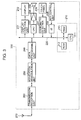
- FIG. 2 An example of the base apparatus 100 is shown in FIG. 2.
- the base apparatus 100 is provided with a CPU 111, and its bus 120 is connected with a ROM 112 into which a program and data are written, a RAM 113 with which the program and data are implemented, etc., to thereby constitute a control unit 110.
- the bus 120 is connected with a TV tuner 131 to which a TV (television) antenna is connected, an external network interface 132 for connecting to external networks, such as the Internet etc., and an external device interface 133 for connecting to external devices, such as a hard disk recorder, a DVD player, etc.
- a TV tuner 131 to which a TV (television) antenna is connected
- an external network interface 132 for connecting to external networks, such as the Internet etc.
- an external device interface 133 for connecting to external devices, such as a hard disk recorder, a DVD player, etc.
- bus 120 is connected to a wireless communications unit including a data processing unit 140, a modulation/demodulation unit 150, a transmission/reception unit 160, and an antenna 170.
- a MAC (Medium Access Control) address of the base apparatus 100 and MAC addresses of the monitor terminal 200 and the repeater apparatus 300, which constitute the wireless LAN system together with the base apparatus 100, are beforehand registered with the base apparatus 100 having the structure.
- FIG. 3 An example of the monitor terminal 200 is shown in FIG. 3.
- the monitor terminal 200 is provided with a CPU 211, and its bus 220 is connected with a ROM 212 into which a program and data are written, a RAM 213 with which the program and data are implemented, etc., to thereby constitute a control unit 210.
- the bus 220 is connected with a display 232, such as a liquid crystal display etc., via a display control unit 231, connected with a speaker 235 via a DAC (D/A converter) 233 and an audio amplification circuit 234, connected with a touch panel 236 via a coordinates detection unit 237, and connected with a key control unit 238 via an interface 239.
- the touch panel 236 is provided on a display screen of the display 232.
- bus 220 is connected with a wireless communications unit including a data processing unit 240, a modulation/demodulation unit 250, a transmission/reception unit 260, and an antenna 270.
- a wireless communications unit including a data processing unit 240, a modulation/demodulation unit 250, a transmission/reception unit 260, and an antenna 270.
- a reception quality (received field strength and noise level) of the data received from the base apparatus 100 in the direct communication mode and a reception level of the beacon received from the base apparatus 100 in the indirect communication mode are detected as will be described later.
- the MAC address of the monitor terminal 200 and the MAC addresses of the base apparatus 100 and the repeater apparatus 300 which constitute the wireless LAN system together with the monitor terminal 200 are beforehand registered with the monitor terminal 200 having the structure.
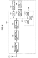
- FIG. 4 An example of the repeater apparatus 300 is shown in FIG. 4.
- the repeater apparatus 300 is provided with a CPU 311, and its bus 320 is connected with a ROM 312 into which a program and data are written, a RAM 313 with which the program and data are implemented, etc., to thereby constitute a control unit 310.
- bus 320 is connected with a setup control unit 331 via an interface 332, and connected with an LED (light emitting diode) display unit 334 via a display control unit 333.
- LED light emitting diode
- bus 320 is connected with a wireless communications unit including a data processing unit 340, a modulation/demodulation unit 350, a transmission/reception unit 360, and an antenna 370.
- the MAC address of the repeater apparatus 300 and the MAC addresses of the base apparatus 100 and the monitor terminal 200 which constitute the wireless LAN system together with the repeater apparatus 300 are beforehand registered with the repeater apparatus 300 having the structure.
- FIG. 4 shows a case where, by means of one wireless communications unit, the repeater apparatus 300 carries out communications with the base apparatus 100 and with the monitor terminal 200 at the time of the indirect communication mode. Therefore, data cannot be simultaneously transmitted to the base apparatus 100 and the monitor terminal 200, and a throughput between the base apparatus 100 and the monitor terminal 200 at the time of the indirect communication mode is about half a throughput between the base apparatus 100 and the monitor terminal 200 at the time of the direct communication mode.
- the repeater apparatus 300 is separately provided with a wireless communications unit for communication with the base apparatus 100 and a wireless communications unit for communication with the monitor terminal 200.
- FIG. 5 shows an example in that case.
- the bus 320 is connected with a wireless communications unit 391 which is constituted by a control unit 381, a data processing unit 341, a modulation/demodulation unit 351, a transmission/reception unit 361, and an antenna 371, and a wireless communications unit 392 which is constituted by a control unit 382, a data processing unit 342, a modulation/demodulation unit 352, a transmission/reception unit 362, and an antenna 372.
- the wireless communications unit 391 is for communication with the base apparatus 100, the wireless communications unit 392 is for communication with the monitor terminal 200, and a frequency channel can be changed between both.
- the throughput between the base apparatus 100 and the monitor terminal 200 at the time of the indirect communication mode can be comparable with the throughput between the base apparatus 100 and the monitor terminal 200 at the time of the direct communication mode.
- the repeater apparatus 300 information about the system is set up in advance by the user by way of a method of using a web browser etc. like an access point of the existing wireless LAN system.
- the control unit 310 of the repeater apparatus 300 checks whether the setup is made at the time of turning on a power supply to the repeater apparatus 300.
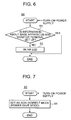
- An example of the setup check processing is shown in FIG. 6.
- the control unit 310 of the repeater apparatus 300 determines in step 51 whether or not information about the base apparatus and the monitor terminal is set up. When it is set up, the setup check process 50 is terminated, leaving the setup as it is. However, when it is not set up, the process moves to step 52 to cause a setup prompting LED of the LED display unit 334 as shown in FIG. 4 or 5 to blink.
- a user looks at it and sets up the information about the base apparatus 100 and the monitor terminal 200, such as the MAC addresses of the base apparatus 100 and the monitor terminal 200 etc. by way of setup operation in the setup control unit 331 as shown in FIGS. 4 or 5.
- control unit 310 of the repeater apparatus 300 performs a starting process as shown in FIG. 7.
- this starting processing is carried out.
- the control unit 310 of the repeater apparatus 300 sets in step 61 the apparatus itself (repeater apparatus 300) as the non-indirect mode i.e. a situation where communication between the base apparatus 100 and the monitor terminal 200 is not relayed. Furthermore, at the same time it sets the apparatus itself (repeater apparatus 300) as a power save mode.
- the monitor terminal 200, the base apparatus 100, and the repeater apparatus 300 perform processes as will be described below, respectively.
- FIG. 8 An example of a process carried out by the monitor terminal 200 in the direct communication mode is shown in FIG. 8.
- the monitor terminal 200 communicates with the base apparatus 100 in step 401 by way of the direct communication mode, detects in step 402 the reception quality of data received from the base apparatus 100, further determines in step 403 whether or not the detected reception quality is equal to or greater than a predetermined threshold value.
- the monitor terminal 200 When the monitor terminal 200 exists in a position comparatively close to the base apparatus 100 in the area 1 as shown in FIG. 1, the data reception level in the monitor terminal 200 is high, and the reception quality is equal to or exceeds the threshold value. However, if the user moves the monitor terminal 200 to the vicinity of a boundary of the area 1 or out of the area 1, the data reception level in the monitor terminal 200 becomes low and the reception quality is less than the threshold value.
- step 403 when it is determined that the reception quality is equal to or greater than the threshold value, the control unit 210 of the monitor terminal 200 returns the process to step 401 to continue the communication in the direct communication mode.
- step 403 when it is determined that the reception quality is less than the threshold value, the control unit 210 of the monitor terminal 200 moves the process to step 404, to notify the base apparatus 100 that the reception quality is less than the threshold value and request a mode change.
- This mode change request is transmitted not as a special frame but as a data frame as specified by the IEEE802.11 standard which is a wireless LAN standard similar to usual data transmitted and received between the base apparatus 100 and the monitor terminal 200.
- the base apparatus 100 requests a mode change of the repeater apparatus 300 by transmitting a beacon. If the mode change is requested by the base apparatus 100, the repeater apparatus 300 notifies the monitor terminal 200 and the base apparatus 100 of changing the mode.
- step 404 the control unit 210 of the monitor terminal 200, in step 405, starts a timer, and further moves the process to step 406, to determine whether or not the notice of the mode change is received from the repeater apparatus 300.
- step 406 when it is determined that the notice of the mode change is not received from the repeater apparatus 300, the control unit 210 of the monitor terminal 200 determines in step 407 whether or not the timer times out. If the timer does not time out, the process returns to step 406, where it is determined whether or not the notice of the mode change is received from the repeater apparatus 300.
- control unit 210 of the monitor terminal 200 waits for the notice of the mode change from the repeater apparatus 300 until a set-up period of time has elapsed.
- the process returns from step 407 to step 401.
- control unit 210 of the monitor terminal 200 moves the process from step 406 to step 408, where a destination address in an address field is changed from the MAC address of the base apparatus 100 till then, into the MAC address of the repeater apparatus 300.
- the process moves to step 409, and shifts to the indirect communication mode.
- the monitor terminal 200 is changed from the direct communication mode to the indirect communication mode.
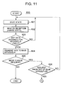
- FIG. 9 An example of a process carried out by the base apparatus 100 in the direct communication mode is shown in FIG. 9 and FIG. 10.
- the base apparatus 100 communicates with the monitor terminal 200 in step 501 by way of the direct communication mode, and determines in step 502 whether or not the mode change request is received from the monitor terminal 200.
- step 502 when it is determined that the mode change request is not received from the monitor terminal 200, the control unit 110 of the base apparatus 100 returns the process to step 501 to continue the communication in the direct communication mode.
- step 502 when it is determined that the mode change request is received from the monitor terminal 200, the control unit 110 of the base apparatus 100 moves the process to step 503, transmits ACK to the monitor terminal 200, further moves the process to step 504, transmits a beacon, and notifies the repeater apparatus 300 by means of the beacon that the data destined for the repeater apparatus 300 exist.
- control unit 110 of the base apparatus 100 in step 505, starts the timer, and further moves the process to step 506, to determine whether or not ACK is received from the repeater apparatus 300.
- step 507 it is determined in step 507 whether or not the timer times out.
- the process returns to step 506 where it is determined whether or not ACK is received from the repeater apparatus 300.
- control unit 110 of the base apparatus 100 waits for ACK from the repeater apparatus 300 until the set-up period of time has elapsed.
- ACK is not received from the repeater apparatus 300 within the set-up period of time, the process returns from step 507 to step 501.
- the control unit 110 of the base apparatus 100 moves the process from step 506 to step 511 and requests a mode change of the repeater apparatus 300.
- This mode change request is also transmitted as a usual data frame within the beacon.
- step 511 asking the repeater apparatus 300 for the mode change, the control unit 110 of the base apparatus 100 starts the timer in step 512, further moves the process to step 513, and determines whether or not the notice of the mode change is received from the repeater apparatus 300.
- step 513 when it is determined that the notice of the mode change is not received from the repeater apparatus 300, the control unit 110 of the base apparatus 100 determines in step 514 whether or not the timer times out. If the timer does not time out, the process returns to step 513 and it is determined whether or not the notice of the mode change is received from the repeater apparatus 300.
- control unit 110 of the base apparatus 100 waits for the notice of the mode change from the repeater apparatus 300 until the set-up period of time has elapsed.
- the process returns from step 514 to step 501.
- control unit 110 of the base apparatus 100 moves the process from step 513 to step 515, the destination address in the address field is changed from the MAC address of the monitor terminal 200 till then, into the MAC address of the repeater apparatus 300, the process moves to step 516 to shift to the indirect communication mode.
- the base apparatus 100 is switched from the direct communication mode to the indirect communication mode by way of the above process.
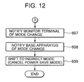
- FIGS. 11 and 12 An example of a process carried out by the repeater apparatus 300 in the direct communication mode is shown in FIGS. 11 and 12. At this time, the repeater apparatus 300 is in the power save mode.
- the repeater apparatus 300 via the doze state in step 601, the repeater apparatus 300 receives the beacon transmitted from the base apparatus 100 in the awake state in step 602, further moves the process to step 603, and determines whether or not the data destined for the apparatus itself (repeater apparatus 300) are in the received beacon.
- the repeater apparatus 300 If there are no data destined for the apparatus itself within the received beacon, the repeater apparatus 300 returns from step 603 to step 601, to be in the doze state.
- control unit 310 of the repeater apparatus 300 moves the process from step 603 to step 604, transmits ACK to the base apparatus 100, further moves the process to step 605, and determines whether or not the data destined for the apparatus itself are for requesting the mode change.
- the control unit 310 of the repeater apparatus 300 terminates the process 600 with respect to the mode change, and shifts to another processing routine.
- the control unit 310 of the repeater apparatus 300 moves the process from step 605 to step 606, and determines whether or not the mode change request is one which is from the base apparatus (base apparatus 100) and set up in the apparatus itself (repeater apparatus 300). When it is not one from the set-up base apparatus (base apparatus 100), the process returns to step 601.
- the repeater apparatus 300 moves the process from step 606 to step 607, notifies the monitor terminal 200 that the mode is changed, and further moves the process to step 608. After notifying the base apparatus 100 of the change of the mode, it moves the process to step 609, cancels the power save mode (becomes the active mode), and shifts to the indirect mode.
- the repeater apparatus 300 is switched from the non-indirect mode (power save mode) to the indirect mode (active mode) by way of the above process.
- the monitor terminal 200, the base apparatus 100, and the repeater apparatus 300 perform processes as will be described below, respectively.
- FIG. 13 An example of a process carried out by the monitor terminal 200 in the indirect communication mode is shown in FIG. 13.
- the monitor terminal 200 communicates with the base apparatus 100 in step 701 via the repeater apparatus 300, directly receives the beacon transmitted from the base apparatus 100 in step 702, and determines in step 703 whether or not the reception level of the beacon is equal to or greater than the predetermined threshold value.
- the reception level when the monitor terminal 200 receives the beacon transmitted from the base apparatus 100 is low and it is less than the threshold value. However, if the user moves the monitor terminal 200 to the vicinity of the boundary of the area 1 or into the area 1, the reception level when the monitor terminal 200 receives the beacon transmitted from the base apparatus 100 increases and is equal to or greater than the threshold value.
- step 703 when it is determined that this beacon reception level is less than the threshold value, the control unit 210 of the monitor terminal 200 returns the process to step 701 to continue the communication in the indirect communication mode.
- step 703 when it is determined that the beacon reception level is equal to or greater than the threshold value, the control unit 210 of the monitor terminal 200 moves the process to step 704, asks the repeater apparatus 300 for the mode change, then starts the timer in step 705, further moves the process to step 706, and determines whether or not the notice of the mode change is received from the repeater apparatus 300.
- step 706 when it is determined that the notice of the mode change is not received from the repeater apparatus 300, the control unit 210 of the monitor terminal 200 determines whether or not the timer times out in step 707. If the timer does not time out, the process returns to step 706 and it is determined whether or not the notice of the mode change is received from the repeater apparatus 300.
- control unit 210 of the monitor terminal 200 waits for the notice of the mode change from the repeater apparatus 300 until the set-up period of time has elapsed.
- the process returns from step 707 to step 701.
- control unit 210 of the monitor terminal 200 moves the process from step 706 to step 708, the destination address in the address field is changed from the MAC address of the repeater apparatus 300 till then, into the MAC address of the base apparatus 100, and the process moves to step 709 to shift to the direct communication mode.
- the monitor terminal 200 is switched from the indirect communication mode to the direct communication mode by way of the above process.
- FIG. 14 An example of a process carried out by the base apparatus 100 in the indirect communication mode is shown in FIG. 14.
- the base apparatus 100 communicates with the monitor terminal 200 in step 801 via the repeater apparatus 300, transmits a beacon in step 802, and determines in step 803 whether or not the mode change request is received via the repeater apparatus 300 from the monitor terminal 200.
- step 803 when it is determined that the mode change request from the monitor terminal 200 through the repeater apparatus 300 is not received, the control unit 110 of the base apparatus 100 returns the process to step 801 to continue the communication in the indirect communication mode.
- step 803 when it is determined that the mode change request from the monitor terminal 200 through the repeater apparatus 300 is received, the control unit 110 of the base apparatus 100 moves the process to step 804, asks the repeater apparatus 300 for the mode change, then starts the timer in step 805, further moves the process to step 806, and determines whether or not the notice of the mode change is received from the repeater apparatus 300.
- step 806 when it is determined that the notice of the mode change is not received from the repeater apparatus 300, the control unit 110 of the base apparatus 100 determines in step 807 whether or not the timer times out. If the timer does not time out, the process returns to step 806 and it is determined whether or not the notice of the mode change is received from the repeater apparatus 300.
- control unit 110 of the base apparatus 100 waits for the notice of the mode change from the repeater apparatus 300 until the set-up period of time has elapsed.
- the process returns from step 807 to step 801.
- control unit 110 of the base apparatus 100 moves the process from step 806 to step 808, the destination address in the address field is changed from the MAC address of the repeater apparatus 300 till then, into the MAC address of the monitor terminal 200, and the process moves to step 809 to shift to the direct communication mode.
- the base apparatus 100 is switched from the indirect communication mode to the direct communication mode by way of the above process.
- FIG. 15 An example of a process carried out by the repeater apparatus 300 in the indirect communication mode is shown in FIG. 15.
- the repeater apparatus 300 in step 901, relays the communication between the base apparatus 100 and the monitor terminal 200, and determines in step 902 whether or not the mode change request is received from the base apparatus.
- the mode change request from the base apparatus 100 is transmitted in step 804 of FIG. 14.
- step 902 when it is determined that the mode change request is not received from the base apparatus, the control unit 310 of the repeater apparatus 300 returns the process to step 901 to continue the relay of the communication between the base apparatus 100 and the monitor terminal 200.
- step 902 when it is determined that the mode change request is received from the base apparatus, the control unit 310 of the repeater apparatus 300 moves the process to step 903, and determines whether or not the mode change request is a mode change request from the base apparatus (base apparatus 100) set up in the apparatus itself (repeater apparatus 300). When it is not the mode change request from the set-up base apparatus (base apparatus 100), the process returns to step 901.
- the repeater apparatus 300 moves the process from step 903 to step 904, notifies the monitor terminal 200 that the mode is changed, and further moves the process to step 905. After notifying the base apparatus 100 of the change of the mode, it moves the process to step 906, shifts to the non-indirect mode to be in the power save mode.
- the repeater apparatus 300 is switched from the indirect mode (active mode) to the non-indirect mode (power save mode) by way of the above process.
- the present invention contains subject mater related to Japanese Patent Application No. JP2005-213858 filed in the Japanese Patent Office on July 25, 2005 , the entire contents of which being incorporated herein by reference.
Landscapes
- Engineering & Computer Science (AREA)
- Computer Networks & Wireless Communication (AREA)
- Signal Processing (AREA)
- Mobile Radio Communication Systems (AREA)
- Small-Scale Networks (AREA)
- Radio Relay Systems (AREA)
Applications Claiming Priority (1)
| Application Number | Priority Date | Filing Date | Title |
|---|---|---|---|
| JP2005213858A JP4292419B2 (ja) | 2005-07-25 | 2005-07-25 | モニタ端末 |
Publications (3)
| Publication Number | Publication Date |
|---|---|
| EP1748576A2 true EP1748576A2 (de) | 2007-01-31 |
| EP1748576A3 EP1748576A3 (de) | 2011-04-20 |
| EP1748576B1 EP1748576B1 (de) | 2012-07-04 |
Family
ID=37398394
Family Applications (1)
| Application Number | Title | Priority Date | Filing Date |
|---|---|---|---|
| EP06253611A Expired - Fee Related EP1748576B1 (de) | 2005-07-25 | 2006-07-11 | Basisstation, Überwachungsgerät und Relaisstation zur Übertragungsweiterleitung |
Country Status (5)
| Country | Link |
|---|---|
| US (1) | US7809328B2 (de) |
| EP (1) | EP1748576B1 (de) |
| JP (1) | JP4292419B2 (de) |
| KR (1) | KR101275900B1 (de) |
| CN (1) | CN1905401B (de) |
Cited By (8)
| Publication number | Priority date | Publication date | Assignee | Title |
|---|---|---|---|---|
| EP2106174A3 (de) * | 2008-03-28 | 2009-12-30 | Fujitsu Ltd. | Relaisstation, Funkkommunikationssystem und Steuerungsverfahren der Relaisstation |
| EP2180605A1 (de) | 2008-10-27 | 2010-04-28 | Andrew Wireless Systems GmbH | Repeater und Verfahren zum Betrieb eines solchen Repeaters |
| EP2289263A1 (de) * | 2008-06-11 | 2011-03-02 | Mitsubishi Electric R&D Centre Europe B.V. | Verfahren und vorrichtung zur entscheidung, ob der betriebsmodus einer telekommunikationsvorrichtung auf einen anderen betriebsmodus umzuschalten ist |
| EP2410786A1 (de) * | 2009-03-18 | 2012-01-25 | ZTE Corporation | Empfangsverfahren und einrichtung für abwärtsstreckendienst im long-term-evolution-system |
| WO2012056212A1 (en) | 2010-10-25 | 2012-05-03 | Enecsys Limited | Renewable energy monitoring system |
| CN101640950B (zh) * | 2009-07-27 | 2012-07-18 | 西瑞克斯(北京)通信设备有限公司 | 可变带宽移频选频数字直放站 |
| US9502902B2 (en) | 2012-06-26 | 2016-11-22 | Solarcity Corporation | System, method and apparatus for generating layout of devices in solar installations |
| US10645667B2 (en) | 2009-04-21 | 2020-05-05 | Commscope Technologies Llc | System for automatic configuration of a mobile communication system |
Families Citing this family (56)
| Publication number | Priority date | Publication date | Assignee | Title |
|---|---|---|---|---|
| US8165301B1 (en) | 2006-04-04 | 2012-04-24 | Bitmicro Networks, Inc. | Input-output device and storage controller handshake protocol using key exchange for data security |
| GB0616475D0 (en) * | 2006-08-18 | 2006-09-27 | Fujitsu Ltd | Communication systems |
| KR100839608B1 (ko) * | 2006-12-14 | 2008-06-20 | 유니챌(주) | 무전기의 긴급호출 제어 시스템 및 그 방법 |
| GB0702771D0 (en) * | 2007-02-13 | 2007-03-21 | Sepura Ltd | Communications systems |
| JP4888431B2 (ja) * | 2007-03-26 | 2012-02-29 | 株式会社富士通ゼネラル | 無線通信システム及び無線通信システムにおける中継方法 |
| CN101291167B (zh) * | 2007-04-20 | 2013-02-27 | 华为技术有限公司 | 一种双模中继站及其入网方法、模式转换方法和控制站点 |
| US8959307B1 (en) | 2007-11-16 | 2015-02-17 | Bitmicro Networks, Inc. | Reduced latency memory read transactions in storage devices |
| US8787825B2 (en) * | 2007-12-14 | 2014-07-22 | Telefonaktiebolaget Lm Ericsson (Publ) | Method and apparatus for controlling the activation of an amplifier arrangement in a repeater device disposed in a radio communication system |
| JP5059588B2 (ja) * | 2007-12-27 | 2012-10-24 | 京セラ株式会社 | 無線通信システム、移動局、基地局、無線通信方法 |
| JP5281312B2 (ja) * | 2008-04-25 | 2013-09-04 | キヤノン株式会社 | 通信装置及びその制御方法、コンピュータプログラム |
| TWI369099B (en) * | 2008-05-08 | 2012-07-21 | Inst Information Industry | Relay station, access point, transmission method, and tangible machine-readable medium thereof for use in a wireless mesh network |
| GB0907213D0 (en) * | 2009-04-27 | 2009-06-10 | Sharp Kk | Relay apparatus and method |
| JP5540592B2 (ja) | 2009-07-23 | 2014-07-02 | ソニー株式会社 | 通信システム、通信制御方法、移動端末、および中継装置 |
| JP5338567B2 (ja) * | 2009-08-25 | 2013-11-13 | 沖電気工業株式会社 | 無線端末及び無線システム |
| US8665601B1 (en) | 2009-09-04 | 2014-03-04 | Bitmicro Networks, Inc. | Solid state drive with improved enclosure assembly |
| US9135190B1 (en) | 2009-09-04 | 2015-09-15 | Bitmicro Networks, Inc. | Multi-profile memory controller for computing devices |
| US8447908B2 (en) | 2009-09-07 | 2013-05-21 | Bitmicro Networks, Inc. | Multilevel memory bus system for solid-state mass storage |
| US8560804B2 (en) * | 2009-09-14 | 2013-10-15 | Bitmicro Networks, Inc. | Reducing erase cycles in an electronic storage device that uses at least one erase-limited memory device |
| JP5546225B2 (ja) * | 2009-12-07 | 2014-07-09 | キヤノン株式会社 | 通信装置、通信装置の制御方法、プログラム |
| WO2011112056A2 (ko) * | 2010-03-11 | 2011-09-15 | 한국전자통신연구원 | 무선 시스템의 조정자 장치, 소스 장치 및 릴레이 장치의 통신 방법 및 프레임 구조 |
| JP5418353B2 (ja) * | 2010-03-25 | 2014-02-19 | ソニー株式会社 | 通信制御方法、および中小規模基地局 |
| CN102215436A (zh) * | 2011-06-15 | 2011-10-12 | 深圳科立讯电子有限公司 | Dmr中转模式下自动脱网的方法 |
| US9372755B1 (en) | 2011-10-05 | 2016-06-21 | Bitmicro Networks, Inc. | Adaptive power cycle sequences for data recovery |
| US9043669B1 (en) | 2012-05-18 | 2015-05-26 | Bitmicro Networks, Inc. | Distributed ECC engine for storage media |
| KR20140001300A (ko) * | 2012-06-25 | 2014-01-07 | 한국전자통신연구원 | 셀룰러 통신 시스템 및 그 통신 방법 |
| JP6109602B2 (ja) * | 2013-02-28 | 2017-04-05 | 西日本電信電話株式会社 | 無線中継器 |
| US9423457B2 (en) | 2013-03-14 | 2016-08-23 | Bitmicro Networks, Inc. | Self-test solution for delay locked loops |
| US9842024B1 (en) | 2013-03-15 | 2017-12-12 | Bitmicro Networks, Inc. | Flash electronic disk with RAID controller |
| US9934045B1 (en) | 2013-03-15 | 2018-04-03 | Bitmicro Networks, Inc. | Embedded system boot from a storage device |
| US10489318B1 (en) | 2013-03-15 | 2019-11-26 | Bitmicro Networks, Inc. | Scatter-gather approach for parallel data transfer in a mass storage system |
| US9720603B1 (en) | 2013-03-15 | 2017-08-01 | Bitmicro Networks, Inc. | IOC to IOC distributed caching architecture |
| US9501436B1 (en) | 2013-03-15 | 2016-11-22 | Bitmicro Networks, Inc. | Multi-level message passing descriptor |
| US9798688B1 (en) | 2013-03-15 | 2017-10-24 | Bitmicro Networks, Inc. | Bus arbitration with routing and failover mechanism |
| US9400617B2 (en) | 2013-03-15 | 2016-07-26 | Bitmicro Networks, Inc. | Hardware-assisted DMA transfer with dependency table configured to permit-in parallel-data drain from cache without processor intervention when filled or drained |
| US9672178B1 (en) | 2013-03-15 | 2017-06-06 | Bitmicro Networks, Inc. | Bit-mapped DMA transfer with dependency table configured to monitor status so that a processor is not rendered as a bottleneck in a system |
| US9971524B1 (en) | 2013-03-15 | 2018-05-15 | Bitmicro Networks, Inc. | Scatter-gather approach for parallel data transfer in a mass storage system |
| US9916213B1 (en) | 2013-03-15 | 2018-03-13 | Bitmicro Networks, Inc. | Bus arbitration with routing and failover mechanism |
| US9430386B2 (en) | 2013-03-15 | 2016-08-30 | Bitmicro Networks, Inc. | Multi-leveled cache management in a hybrid storage system |
| US9875205B1 (en) | 2013-03-15 | 2018-01-23 | Bitmicro Networks, Inc. | Network of memory systems |
| US9858084B2 (en) | 2013-03-15 | 2018-01-02 | Bitmicro Networks, Inc. | Copying of power-on reset sequencer descriptor from nonvolatile memory to random access memory |
| US9734067B1 (en) | 2013-03-15 | 2017-08-15 | Bitmicro Networks, Inc. | Write buffering |
| CN103533642B (zh) * | 2013-10-16 | 2016-07-06 | 厦门市美亚柏科信息股份有限公司 | Wifi终端的定位方法和定位装置 |
| JP5655923B2 (ja) * | 2013-11-18 | 2015-01-21 | ソニー株式会社 | 中小規模基地局 |
| US10042792B1 (en) | 2014-04-17 | 2018-08-07 | Bitmicro Networks, Inc. | Method for transferring and receiving frames across PCI express bus for SSD device |
| US9952991B1 (en) | 2014-04-17 | 2018-04-24 | Bitmicro Networks, Inc. | Systematic method on queuing of descriptors for multiple flash intelligent DMA engine operation |
| US9811461B1 (en) | 2014-04-17 | 2017-11-07 | Bitmicro Networks, Inc. | Data storage system |
| US10055150B1 (en) | 2014-04-17 | 2018-08-21 | Bitmicro Networks, Inc. | Writing volatile scattered memory metadata to flash device |
| US10025736B1 (en) | 2014-04-17 | 2018-07-17 | Bitmicro Networks, Inc. | Exchange message protocol message transmission between two devices |
| US10078604B1 (en) | 2014-04-17 | 2018-09-18 | Bitmicro Networks, Inc. | Interrupt coalescing |
| EP3035728A1 (de) | 2014-12-16 | 2016-06-22 | Thomson Licensing | Verfahren zur selektiven Aktivierung eines drahtlosen Zugangspunktes oder Repeaters |
| JP2017184002A (ja) * | 2016-03-30 | 2017-10-05 | Necプラットフォームズ株式会社 | 通信装置、方法及びプログラム |
| US10552050B1 (en) | 2017-04-07 | 2020-02-04 | Bitmicro Llc | Multi-dimensional computer storage system |
| KR101951804B1 (ko) * | 2017-10-13 | 2019-02-25 | 인천대학교 산학협력단 | 밀리미터파 대역에서 디바이스 간 통신 경로를 선택하는 장치 및 이의 동작 방법 |
| KR102343570B1 (ko) * | 2018-02-19 | 2021-12-28 | 미쓰비시 덴키 빌딩 테크노 서비스 가부시키 가이샤 | 무선 통신 장치 |
| US11290238B2 (en) * | 2018-05-29 | 2022-03-29 | Cable Television Laboratories, Inc. | Systems and methods for customizing wireless communication beacons and transmitting wireless communication beacons |
| WO2023156408A1 (en) * | 2022-02-21 | 2023-08-24 | Sony Group Corporation | Beacon signals for beam management at coverage enhancing device |
Citations (5)
| Publication number | Priority date | Publication date | Assignee | Title |
|---|---|---|---|---|
| EP0169384A1 (de) | 1984-06-22 | 1986-01-29 | Nec Corporation | Verfahren zur Herstellung einer Relais-Fernsprechverbindung zwischen einer mobilen Einheit und einer ortsfesten Station und dafür geeigneter Verstärker |
| WO2002052753A1 (en) | 2000-12-22 | 2002-07-04 | Rangestar Wireless, Inc. | Repeater system |
| JP2003124965A (ja) | 2001-10-17 | 2003-04-25 | Sony Corp | リピータ装置 |
| US6877104B1 (en) | 1999-03-29 | 2005-04-05 | Nec Infiontia Corporation | Wireless local area network system, fault recovery method, and recording medium stored therein a computer program executing the fault recovery process |
| JP2005213858A (ja) | 2004-01-29 | 2005-08-11 | Marsima Aqua System Corp | 選択取水設備 |
Family Cites Families (12)
| Publication number | Priority date | Publication date | Assignee | Title |
|---|---|---|---|---|
| JPH03278727A (ja) | 1990-03-28 | 1991-12-10 | Ricoh Co Ltd | 移動体間回線接続方式 |
| JPH06261043A (ja) | 1993-03-05 | 1994-09-16 | Hitachi Ltd | 無線lanシステム及びその制御方法 |
| JPH0884373A (ja) | 1994-07-13 | 1996-03-26 | Nec Corp | 移動通信ネットワークおよびそのための通信方式 |
| JPH099332A (ja) | 1995-06-22 | 1997-01-10 | Matsushita Electric Works Ltd | 無線システムのセル切換方法 |
| JP2000269884A (ja) * | 1999-03-19 | 2000-09-29 | Fujitsu General Ltd | 無線通信システム |
| JP2001156788A (ja) | 1999-11-24 | 2001-06-08 | Matsushita Electric Ind Co Ltd | 無線lanアクセスポイント |
| JP4639008B2 (ja) | 2001-08-08 | 2011-02-23 | クラリオン株式会社 | 無線端末、ビーコン局及び無線通信システム |
| JP3636695B2 (ja) | 2002-02-22 | 2005-04-06 | エヌ・ティ・ティ・コムウェア株式会社 | 無線通信システムにおける中継端末装置及び中継端末プログラム |
| JP2003304253A (ja) * | 2002-04-11 | 2003-10-24 | Canon Inc | 通信方法 |
| US20040146013A1 (en) * | 2003-01-22 | 2004-07-29 | Hong Kong Applied Science And Technology Research Institute Co., Ltd | Wireless local area network time division duplex relay system with high speed automatic up-link and down-link detection |
| JP2005184314A (ja) * | 2003-12-18 | 2005-07-07 | Matsushita Electric Ind Co Ltd | 無線通信装置 |
| US20050143119A1 (en) | 2003-12-31 | 2005-06-30 | Interdigital Technology Corporation | Method and apparatus for providing individual power control information in a wireless local area network/wireless wide area network (WLAN/WWAN) |
-
2005
- 2005-07-25 JP JP2005213858A patent/JP4292419B2/ja active Active
-
2006
- 2006-07-11 EP EP06253611A patent/EP1748576B1/de not_active Expired - Fee Related
- 2006-07-21 CN CN2006101059987A patent/CN1905401B/zh not_active Expired - Fee Related
- 2006-07-24 KR KR1020060069111A patent/KR101275900B1/ko active IP Right Grant
- 2006-07-24 US US11/491,739 patent/US7809328B2/en not_active Expired - Fee Related
Patent Citations (5)
| Publication number | Priority date | Publication date | Assignee | Title |
|---|---|---|---|---|
| EP0169384A1 (de) | 1984-06-22 | 1986-01-29 | Nec Corporation | Verfahren zur Herstellung einer Relais-Fernsprechverbindung zwischen einer mobilen Einheit und einer ortsfesten Station und dafür geeigneter Verstärker |
| US6877104B1 (en) | 1999-03-29 | 2005-04-05 | Nec Infiontia Corporation | Wireless local area network system, fault recovery method, and recording medium stored therein a computer program executing the fault recovery process |
| WO2002052753A1 (en) | 2000-12-22 | 2002-07-04 | Rangestar Wireless, Inc. | Repeater system |
| JP2003124965A (ja) | 2001-10-17 | 2003-04-25 | Sony Corp | リピータ装置 |
| JP2005213858A (ja) | 2004-01-29 | 2005-08-11 | Marsima Aqua System Corp | 選択取水設備 |
Cited By (20)
| Publication number | Priority date | Publication date | Assignee | Title |
|---|---|---|---|---|
| EP2106174A3 (de) * | 2008-03-28 | 2009-12-30 | Fujitsu Ltd. | Relaisstation, Funkkommunikationssystem und Steuerungsverfahren der Relaisstation |
| US8401463B2 (en) | 2008-03-28 | 2013-03-19 | Fujitsu Limited | Relay station, radio communication system, and control method of relay station |
| EP2289263A1 (de) * | 2008-06-11 | 2011-03-02 | Mitsubishi Electric R&D Centre Europe B.V. | Verfahren und vorrichtung zur entscheidung, ob der betriebsmodus einer telekommunikationsvorrichtung auf einen anderen betriebsmodus umzuschalten ist |
| WO2010049054A1 (de) * | 2008-10-27 | 2010-05-06 | Andrew Wireless Systems Gmbh | Repeater und verfahren zum betrieb eines solchen repeaters |
| US10511376B2 (en) | 2008-10-27 | 2019-12-17 | Andrew Wireless Systems Gmbh | Repeater and method for operating such a repeater |
| EP2180605A1 (de) | 2008-10-27 | 2010-04-28 | Andrew Wireless Systems GmbH | Repeater und Verfahren zum Betrieb eines solchen Repeaters |
| AT13329U1 (de) * | 2008-10-27 | 2013-10-15 | Andrew Wireless Systems Gmbh | Repeater und Verfahren zum Betrieb eines solchen Repeaters |
| CN102246431B (zh) * | 2008-10-27 | 2016-06-22 | 安德鲁无线系统有限公司 | 中继站和使这种中继站运行的方法 |
| US8830882B2 (en) | 2008-10-27 | 2014-09-09 | Andrew Wireless Systems Gmbh | Repeater and method for operating such a repeater |
| EP2410786A4 (de) * | 2009-03-18 | 2014-10-22 | Zte Corp | Empfangsverfahren und einrichtung für abwärtsstreckendienst im long-term-evolution-system |
| EP2410786A1 (de) * | 2009-03-18 | 2012-01-25 | ZTE Corporation | Empfangsverfahren und einrichtung für abwärtsstreckendienst im long-term-evolution-system |
| US10645667B2 (en) | 2009-04-21 | 2020-05-05 | Commscope Technologies Llc | System for automatic configuration of a mobile communication system |
| CN101640950B (zh) * | 2009-07-27 | 2012-07-18 | 西瑞克斯(北京)通信设备有限公司 | 可变带宽移频选频数字直放站 |
| WO2012056212A1 (en) | 2010-10-25 | 2012-05-03 | Enecsys Limited | Renewable energy monitoring system |
| US8624443B2 (en) | 2010-10-25 | 2014-01-07 | Enecsys Limited | Renewable energy monitoring system |
| US9453861B2 (en) | 2010-10-25 | 2016-09-27 | Solarcity Corporation | Renewable energy monitoring system |
| US10215783B2 (en) | 2010-10-25 | 2019-02-26 | Solarcity Corporation | Renewable energy monitoring system |
| GB2485335B (en) * | 2010-10-25 | 2012-10-03 | Enecsys Ltd | Renewable energy monitoring system |
| GB2485335A (en) * | 2010-10-25 | 2012-05-16 | Enecsys Ltd | Wireless monitoring and control of solar photovoltaic devices using repeaters |
| US9502902B2 (en) | 2012-06-26 | 2016-11-22 | Solarcity Corporation | System, method and apparatus for generating layout of devices in solar installations |
Also Published As
| Publication number | Publication date |
|---|---|
| JP4292419B2 (ja) | 2009-07-08 |
| US7809328B2 (en) | 2010-10-05 |
| KR20070013226A (ko) | 2007-01-30 |
| CN1905401A (zh) | 2007-01-31 |
| KR101275900B1 (ko) | 2013-06-14 |
| JP2007036423A (ja) | 2007-02-08 |
| CN1905401B (zh) | 2012-07-18 |
| EP1748576B1 (de) | 2012-07-04 |
| EP1748576A3 (de) | 2011-04-20 |
| US20070019573A1 (en) | 2007-01-25 |
Similar Documents
| Publication | Publication Date | Title |
|---|---|---|
| US7809328B2 (en) | Base apparatus, monitor terminal and repeater apparatus | |
| US10912083B2 (en) | Wireless router or residential gateway capable of distinguishing power-sensitive wireless sensors and providing separate treatment thereto | |
| CN102308657B (zh) | 上行资源授权过程的优化 | |
| US8660617B1 (en) | WiMAX enhanced sleep mode | |
| EP2547166A1 (de) | Verfahren zur Steuerung des nicht kontinuierlichen Empfangs bei einer mobilen Kommunikationsvorrichtung | |
| WO2022028545A1 (zh) | 免授权频谱的信道接入方法、终端及网络侧设备 | |
| WO2020029914A1 (zh) | 多模通信方法、终端和网络侧设备 | |
| JP2024516949A (ja) | サイドリンクフィードバックリソースの決定方法、端末及びネットワーク側機器 | |
| US20220295374A1 (en) | Electronic apparatus, wireless communication method and computer-readable medium | |
| CN113784433B (zh) | 寻呼周期更新方法、通信设备、通信系统及存储介质 | |
| JP4079832B2 (ja) | 電波干渉解消方法,およびステーション装置 | |
| CN113395749B (zh) | 传输配置方法及电子设备 | |
| CN112333795A (zh) | 网络接入方法及装置 | |
| CN114080009A (zh) | 传输控制方法、装置及相关设备 | |
| KR20100027335A (ko) | 무선통신시스템에서 단말의 휴면 모드 제어 장치 및 방법 | |
| WO2022206970A1 (zh) | 传输处理方法、终端及网络侧设备 | |
| WO2023078327A1 (zh) | 上行传输信息确定、上行传输以及上行传输配置的方法 | |
| US20240049344A1 (en) | Information transmission method and apparatus and communication device | |
| WO2022188836A1 (zh) | Cot确定方法、上行传输方法和设备 | |
| KR20100118535A (ko) | 다중 반송파 무선 접속 시스템에서 데이터를 송수신하는 방법 | |
| WO2023006091A1 (zh) | 放大器的控制方法、放大器及网络侧设备 | |
| WO2023104077A1 (zh) | 能力限制方法、终端及网络侧设备 | |
| WO2022206542A1 (zh) | 信号检测方法、信息发送方法、装置、设备和存储介质 | |
| WO2022206648A1 (zh) | 侧链路非连续接收的实现方法、装置及终端 | |
| WO2022166942A1 (zh) | 发射链路的处理方法、装置及终端 |
Legal Events
| Date | Code | Title | Description |
|---|---|---|---|
| PUAI | Public reference made under article 153(3) epc to a published international application that has entered the european phase |
Free format text: ORIGINAL CODE: 0009012 |
|
| AK | Designated contracting states |
Kind code of ref document: A2 Designated state(s): AT BE BG CH CY CZ DE DK EE ES FI FR GB GR HU IE IS IT LI LT LU LV MC NL PL PT RO SE SI SK TR |
|
| AX | Request for extension of the european patent |
Extension state: AL BA HR MK YU |
|
| PUAL | Search report despatched |
Free format text: ORIGINAL CODE: 0009013 |
|
| AK | Designated contracting states |
Kind code of ref document: A3 Designated state(s): AT BE BG CH CY CZ DE DK EE ES FI FR GB GR HU IE IS IT LI LT LU LV MC NL PL PT RO SE SI SK TR |
|
| AX | Request for extension of the european patent |
Extension state: AL BA HR MK RS |
|
| 17P | Request for examination filed |
Effective date: 20111019 |
|
| AKX | Designation fees paid |
Designated state(s): DE FR GB |
|
| GRAP | Despatch of communication of intention to grant a patent |
Free format text: ORIGINAL CODE: EPIDOSNIGR1 |
|
| RIN1 | Information on inventor provided before grant (corrected) |
Inventor name: NISHIMURA, MASAKI, |
|
| GRAS | Grant fee paid |
Free format text: ORIGINAL CODE: EPIDOSNIGR3 |
|
| GRAA | (expected) grant |
Free format text: ORIGINAL CODE: 0009210 |
|
| AK | Designated contracting states |
Kind code of ref document: B1 Designated state(s): DE FR GB |
|
| REG | Reference to a national code |
Ref country code: GB Ref legal event code: FG4D |
|
| REG | Reference to a national code |
Ref country code: DE Ref legal event code: R096 Ref document number: 602006030528 Country of ref document: DE Effective date: 20120830 |
|
| PLBE | No opposition filed within time limit |
Free format text: ORIGINAL CODE: 0009261 |
|
| STAA | Information on the status of an ep patent application or granted ep patent |
Free format text: STATUS: NO OPPOSITION FILED WITHIN TIME LIMIT |
|
| 26N | No opposition filed |
Effective date: 20130405 |
|
| REG | Reference to a national code |
Ref country code: DE Ref legal event code: R097 Ref document number: 602006030528 Country of ref document: DE Effective date: 20130405 |
|
| REG | Reference to a national code |
Ref country code: FR Ref legal event code: PLFP Year of fee payment: 11 |
|
| REG | Reference to a national code |
Ref country code: FR Ref legal event code: PLFP Year of fee payment: 12 |
|
| REG | Reference to a national code |
Ref country code: FR Ref legal event code: PLFP Year of fee payment: 13 |
|
| PGFP | Annual fee paid to national office [announced via postgrant information from national office to epo] |
Ref country code: FR Payment date: 20190725 Year of fee payment: 14 |
|
| PGFP | Annual fee paid to national office [announced via postgrant information from national office to epo] |
Ref country code: GB Payment date: 20190729 Year of fee payment: 14 |
|
| PGFP | Annual fee paid to national office [announced via postgrant information from national office to epo] |
Ref country code: DE Payment date: 20190930 Year of fee payment: 14 |
|
| REG | Reference to a national code |
Ref country code: DE Ref legal event code: R119 Ref document number: 602006030528 Country of ref document: DE |
|
| GBPC | Gb: european patent ceased through non-payment of renewal fee |
Effective date: 20200711 |
|
| PG25 | Lapsed in a contracting state [announced via postgrant information from national office to epo] |
Ref country code: FR Free format text: LAPSE BECAUSE OF NON-PAYMENT OF DUE FEES Effective date: 20200731 Ref country code: GB Free format text: LAPSE BECAUSE OF NON-PAYMENT OF DUE FEES Effective date: 20200711 |
|
| PG25 | Lapsed in a contracting state [announced via postgrant information from national office to epo] |
Ref country code: DE Free format text: LAPSE BECAUSE OF NON-PAYMENT OF DUE FEES Effective date: 20210202 |