EP1742563B1 - Geschirrspülmaschine mit einem höhenverstellbaren oberkorb - Google Patents
Geschirrspülmaschine mit einem höhenverstellbaren oberkorb Download PDFInfo
- Publication number
- EP1742563B1 EP1742563B1 EP05733894A EP05733894A EP1742563B1 EP 1742563 B1 EP1742563 B1 EP 1742563B1 EP 05733894 A EP05733894 A EP 05733894A EP 05733894 A EP05733894 A EP 05733894A EP 1742563 B1 EP1742563 B1 EP 1742563B1
- Authority
- EP
- European Patent Office
- Prior art keywords
- height
- dishwasher
- pipe
- adjustable upper
- upper basket
- Prior art date
- Legal status (The legal status is an assumption and is not a legal conclusion. Google has not performed a legal analysis and makes no representation as to the accuracy of the status listed.)
- Expired - Lifetime
Links
- 239000007921 spray Substances 0.000 claims abstract description 18
- 230000008878 coupling Effects 0.000 claims description 23
- 238000010168 coupling process Methods 0.000 claims description 23
- 238000005859 coupling reaction Methods 0.000 claims description 23
- 239000007788 liquid Substances 0.000 claims description 23
- 238000005406 washing Methods 0.000 claims description 17
- 238000003780 insertion Methods 0.000 claims description 13
- 230000037431 insertion Effects 0.000 claims description 13
- 239000011324 bead Substances 0.000 claims description 8
- 238000007789 sealing Methods 0.000 claims description 3
- XLYOFNOQVPJJNP-UHFFFAOYSA-N water Substances O XLYOFNOQVPJJNP-UHFFFAOYSA-N 0.000 abstract 4
- 238000004851 dishwashing Methods 0.000 abstract 1
- 230000007704 transition Effects 0.000 description 3
- 239000012530 fluid Substances 0.000 description 2
- 238000003032 molecular docking Methods 0.000 description 2
- 230000001447 compensatory effect Effects 0.000 description 1
- 238000011161 development Methods 0.000 description 1
- 230000018109 developmental process Effects 0.000 description 1
- 230000000694 effects Effects 0.000 description 1
- 238000002955 isolation Methods 0.000 description 1
- 238000004519 manufacturing process Methods 0.000 description 1
Images


Classifications
-
- A—HUMAN NECESSITIES
- A47—FURNITURE; DOMESTIC ARTICLES OR APPLIANCES; COFFEE MILLS; SPICE MILLS; SUCTION CLEANERS IN GENERAL
- A47L—DOMESTIC WASHING OR CLEANING; SUCTION CLEANERS IN GENERAL
- A47L15/00—Washing or rinsing machines for crockery or tableware
- A47L15/42—Details
- A47L15/50—Racks ; Baskets
- A47L15/508—Hydraulic connections for racks
Definitions
- the invention relates to a dishwasher with a height-adjustable upper basket, on which a spray arm and an inflow pipe leading to the spray arm is arranged, the inflow pipe piece, in the inserted state of the basket into the rinsing container in the rear basket area via a funnel opening with a pivotable coupling element in combination, the in turn, for the supply of the spray arm with rinsing liquid with a stationary liquid line in the washing compartment is in operative connection.
- a height-adjustable upper basket known; in which an inflow pipe piece running on the basket bottom is arranged, which cooperates with a spray arm arranged below the basket.
- an S-shaped pipe connection piece is provided which is rotatably connected to the inflow pipe section.
- this end has an integrally formed funnel region which comes into operative connection with the stationary liquid nozzle when the basket is inserted.
- coupling element is carried out when changing the basket height no automatic height adjustment of the coupling element. The height of the coupling point must also be changed manually.
- the basket is moved to a different level, it is necessary that the S-shaped pipe bend must be aligned accordingly, so that a flush coupling can be done.
- the invention thus raises the problem of creating a transition between the stationary liquid line and the Zu plantrohr consultancy for the spray arm in a dishwasher with a height-adjustable upper basket of the type mentioned, which overcomes the disadvantages, in particular long waterways, parking space losses in the basket, and a limited Korb Bonnenverstell Scheme to be prevented.
- the offset between the nozzle and hopper tube in the horizontal direction, which results from the pivoting movement is kept very low.
- even the smallest angular changes of the pivoting tube are sufficient due to the large distance between the pivot point and the coupling point in order to achieve a comparatively large adjustment.
- the swivel tube is positioned so that it is horizontal in the middle position. As a result, the pivoting range is divided into an area above and an area below the middle position, which halves the maximum lateral deflection.
- the invention provides that the pivot tube is fixed by means of a backdrop-like guide on the rear wall of the spray container. It is also advantageous if the frictional force between the pivot tube and its bearing in the region of the liquid line and in the region of the rear wall is greater than the weight of the pivot tube dimensioned. This ensures that the pivot tube remains in its position when no basket adjustment, which in turn reduces the friction between the coupling elements and thus the wear.
- a ball joint is provided in the connection region between the end of the pivot tube and the stationary fluid line, which in addition to the pivoting movement allows a certain translational movement of the pivot tube relative to the rear wall of the washing container. This can be achieved that in particular the coupling is not hindered by a pivoting arc movement.
- a circumferential bead is formed, which cooperates sealingly with the plugged end portion of the pivot tube. It is therefore understood that when the pivot tube is pivoted, the ball joint formed as a joint compensates for the resulting arc in which takes place in the ball joint a certain compensatory translational movement.
- the bead is expediently designed as a spherical section.
- the funnel opening is formed on the inflow pipe piece with the chamfers asymmetrical to the center line of the pipe axis and at the pipe socket end an insertion is preferably formed by an extending at an angle of 50 ° to 60 ° outlet opening.
- an insertion is preferably formed by an extending at an angle of 50 ° to 60 ° outlet opening.
- FIG. 1 shows in the schematic representation of a height-adjustable upper basket 1 in a dishwasher 2, wherein below the upper basket a rotatably arranged spray arm 3 and an extending on the bottom basket 4 inflow pipe section 5 is arranged to better recognize in the FIG. 2 ,
- the inflow pipe section 5 occurs in the inserted state of the basket 1 in the washing compartment 6 with a leveling the coupling element 7 in Connection, which in turn is connected to the supply of the spray arm 3 with rinsing liquid with a stationary liquid line 8 in the washing compartment 6 in operative connection.
- the coupling element 7, better seen in the FIG. 4 includes a fixed to the rear wall 9 of the washing compartment 6, and preferably over half the rear wall 9 extending pivot tube 10 which is connected at its one end 11 with the emerging from the side wall 12 of the washing compartment 6 stationary liquid line 8.
- a running at a right angle pipe socket end 14 is formed, which aligns the pivot tube 10 by means of corresponding insertion bevels 15, 16, 17 to the given level of the basket 1 for feeding the spray arm 3 with rinsing liquid.
- the corresponding alignments are better in the FIG. 1 as well as in the FIG. 4 to recognize where dash-dotted lines the corresponding elevations of the pipe socket end 14 are indicated.
- an insertion bevel 15 is preferably provided by an outlet opening 18 extending at an angle of 50 to 60 degrees at the pipe socket end 14, which with a funnel opening 20 formed asymmetrically to the center line 19 of the pipe axis, which form the corresponding insertion bevels 16 and 17 at the Coupling interact.
- the above the center line 19 arranged insertion bevel 16 is preferably at an angle of 50 to 60 degrees, whereas the arranged below the center line 19 insertion bevel 17 preferably extends at an angle of 30 to 40 degrees.
- the upper approach of the slope 15 cooperates with the insertion bevel 16. If the pipe socket end 14 is below the center line 19, then the running bevel 15 of the pipe socket end 14 cooperates with the insertion bevel 17 arranged below the center line 19. If the upper basket 1 is in the middle level position, an aligned docking of the pipe socket end 14 is provided. In this way it is ensured that in different positions of the pipe socket end 14 is always given a safe docking.
- FIG. 4 shows in isolation the pivot tube 10, wherein the dashed lines represent the corresponding orientations of the pivot tube with its pipe socket end 14 in the possible here three positions with respect to the center line 19.
- the pivot tube 10 is fixed by means of a backdrop-like guide 21 on the rear wall 9 of the washing compartment 6. This results in a stable position of the pivotally mounted tube, which also increases the Ankoppelview.
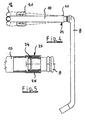
- a ball joint 23 is provided, as shown in an exposed representation in the FIG. 5 can be seen more clearly.
- This ball joint 23 also allows a certain translational movement of the pivot tube 10 on the rear wall 9 of the washing compartment 6.
- a circumferential bead 24 in the form of a spherical segment is formed, which cooperates in a sealing manner with the plugged-on end region 11 of the pivoting tube 10.
- the pivot tube 10 is pivoted above or below the center line 19, as a result of the retracting basket 1, the plugged end portion 25 of the pivot tube 10 moves on the circumferential bead 24 due to the positive guidance of the pivot tube 10.
- the ball joint 23 is at least in the region of the bead 24th elastically formed to achieve a sufficient sealing effect.
- a fixed coupling of the pivot tube 10 may be selected to the liquid line 8, in which case the elasticity of the tube is used for the pivoting operation in the height adjustment of the upper basket.
- this variant may possibly be dispensed with a guide on the rear wall 9 of the washing compartment 6.
Landscapes
- Washing And Drying Of Tableware (AREA)
- Centrifugal Separators (AREA)
- Rigid Containers With Two Or More Constituent Elements (AREA)
Description
- Die Erfindung betrifft eine Geschirrspülmaschine mit einem höhenverstellbaren Oberkorb, an dem ein Sprüharm sowie ein zum Sprüharm führendes Zuflussrohrstück angeordnet ist, wobei das Zuflussrohrstück, im eingeschobenen Zustand des Korbes in den Spülbehälter im hinteren Korbbereich über eine Trichteröffnung mit einem schwenkbaren Kupplungselement in Verbindung tritt, das wiederum zur Speisung des Sprüharms mit Spülflüssigkeit mit einer ortsfesten Flüssigkeitsleitung im Spülbehälter in Wirkverbindung steht.
- So ist beispielsweise aus der
DE 27 32 540 C2 ein höhenverstellbarer Oberkorb bekannt; bei dem ein am Korbboden verlaufendes Zuflussrohrstück angeordnet ist, welches mit einem unterhalb des Korbes angeordneten Sprüharm zusammenwirkt. Zur Ankoppelung des Zuflussrohrstücks an die ortsfeste Flüssigkeitsleitung, die aus der Rückwand des Spülbehälters austritt, wird ein S-förmiges Rohranschlussstück vorgesehen, welches drehbar an dem Zuflussrohrstück angeschlossen ist. Zur Ankopplung des S-förmigen Kupplungselementes weist dieses endseitig einen angeformten Trichterbereich auf, der in Wirkverbindung mit dem ortsfesten Flüssigkeitsstutzen tritt, wenn der Korb eingeschoben wird. Bei diesem nach dem Stand der Technik bekannten Kupplungselement erfolgt bei Änderung der Korbhöhe keine automatische Höhenverstellung des Ankuppelelementes. Die Höhe der Ankoppelstelle muss zusätzlich manuell verändert werden. Wird also bei dieser Ausführung des Standes der Technik der Korb in ein anderes Niveau verbracht, so ist es erforderlich, dass der S-förmige Rohrbogen entsprechend ausgerichtet werden muss, damit eine bündige Kopplung erfolgen kann. - Ein anderes Ausführungsbeispiel gemäß dem Stand der Technik ist in der
DE 27 32 665 C2 beschrieben, welches dem Grunde nach die geschilderten Nachteile derDE 27 32 540 C2 dadurch überwindet, dass an dem Zuflussrohrstück endseitig eine Zentriereinrichtung in Form eines Trichters angeordnet ist, die mit einem schwenkbar an der ortsfesten Flüssigkeitsleitung angeordneten Krümmer zusammenwirkt. Hierdurch wird der Krümmer entsprechend der verstellten Höhenlage des Korbes ausgerichtet, so dass ein Strömungsübergang in unterschiedlichen Niveaustellungen geschaffen wird. Bei dieser Ausführungsform des Standes der Technik wird es als nachteilig angesehen, dass sich der Anstellwinkel des als Kupplungselement ausgebildeten Krümmers sehr stark ändert, weil das Gelenk nahe an der Koppelstelle sitzt. Diese Art der Ankopplung bewirkt schon bei einer geringen Höhenverstellung des Korbes einen großen Winkelversatz zwischen dem Stutzen an der Rückwand und dem Trichterrohr im Korb. Hierdurch ist ein abgedichteter Übergang zwischen beiden Teilen problematisch. - Der Erfindung stellt sich somit das Problem, bei einer Geschirrspülmaschine mit einem höhenverstellbaren Oberkorb der eingangs genannten Art einen Übergang zwischen der ortsfesten Flüssigkeitsleitung und dem Zuflussrohrstück für den Sprüharm zu schaffen, der die geschilderten Nachteile überwindet, wobei im besonderen lange Wasserwege, Stellplatzverluste im Korb, sowie ein eingeschränkter Korbhöhenverstellbereich, unterbunden werden sollen.
- Erfindungsgemäß wird dieses Problem mit dem Merkmal des Anspruchs 1 gelöst. Vorteilhafte Ausgestaltungen und Weiterbildungen der Erfindung ergeben sich aus den nachfolgenden Unteransprüchen.
- Die mit der Erfindung erreichbaren Vorteile bestehen darin, dass durch die groß gehaltene Entfernung zwischen Drehpunkt und Ankoppelpunkt des Schwenkrohres sich kleine Winkeländerungen ergeben, so dass eine stufenlose Höhenverstellung über einen großen Bereich ermöglicht wird, wobei sich im Korbbereich keine beweglichen Teile mehr befinden, die die Stellfläche beeinträchtigen. Ebenfalls kann durch die Herausführung der Flüssigkeitsleitung aus der Seitenwand ein kurzer Spülflüssigkeitsweg realisiert werden. Das an der Spülbehälterwand positionierte Rohr ist dabei samt seines Stutzenendes schwenkbar. Durch die Verlagerung der Drehachse an die Seitenwand entsteht bei keiner Korbsituation ein Winkelversatz zwischen Stutzen und Trichterrohr, was das Ankoppeln erheblich vereinfacht. Damit ist das System für einen wesentlich größeren Höhenverstellbereich einsetzbar.
- Der Versatz zwischen Stutzen und Trichterrohr in horizontaler Richtung, der sich durch die Schwenkbewegung ergibt, wird sehr gering gehalten. Zum einen reichen durch den großen Abstand des Drehpunktes zur Koppelstelle schon kleinste Winkeländerungen des Schwenkrohres aus, um eine vergleichsweise große Verstellung zu erreichen. Zum anderen ist das Schwenkrohr so positioniert, dass es in Mittelstellung waagerecht steht. Dadurch teilt sich der Schwenkbereich in einen Bereich oberhalb und einen Bereich unterhalb der Mittelstellung auf, was die maximale seitliche Auslenkung halbiert.
- Zur sicheren und stabilen Halterung des Schwenkrohres wird erfindungsgemäß vorgesehen, dass das Schwenkrohr mittels einer kulissenartigen Führung an der Rückwand des Sprühbehälters befestigt ist. Es ist außerdem vorteilhaft, wenn die Reibkraft zwischen dem Schwenkrohr und seiner Lagerung im Bereich der Flüssigkeitsleitung und im Bereich der Rückwand größer als die Gewichtskraft des Schwenkrohrs bemessen ist. Hierdurch wird sichergestellt, dass das Schwenkrohr in seiner Position verbleibt, wenn keine Korbverstellung erfolgt, was wiederum die Reibung zwischen den Kupplungselementen und damit den Verschleiß verringert.
- In vorteilhafter Weise ist im Verbindungsbereich zwischen dem Ende des Schwenkrohres und der ortsfesten Flüssigkeitsleitung ein Kugelgelenk vorgesehen, welches neben der Schwenkbewegung eine gewisse translatorische Bewegung des Schwenkrohres gegenüber der Rückwand des Spülbehälters zulässt. Dadurch kann erreicht werden, dass insbesondere die Ankopplung nicht durch eine Schwenkbogenbewegung behindert wird. Durch die Verwendung eines Kugelgelenks können außerdem fertigungsbedingte Toleranzen der Spülbehälterwand in Auszugsrichtung des Korbs ausgeglichen werden.
- Auf dem Endbereich der Flüssigkeitsleitung ist eine umlaufende Wulst angeformt, die dichtend mit dem aufgesteckten Endbereich des Schwenkrohres zusammenwirkt. Es versteht sich daher, dass, wenn das Schwenkrohr verschwenkt wird, die als Verbindungsstelle ausgebildete Kugelgelenkverbindung den sich ergebenden Bogen ausgleicht, in dem im Kugelgelenk eine gewisse ausgleichende translatorische Bewegung stattfindet. Die Wulst ist in zweckmäßiger Weise als Kugelabschnitt ausgebildet.
- Es erweist es sich als besonders vorteilhaft, wenn die Trichteröffnung am Zuflussrohrstück mit den Einführschrägen asymmetrisch zur Mittellinie der Rohrachse ausgebildet ist und am Rohrstutzenende eine Einführschräge vorzugsweise durch eine unter einem Winkel von 50° bis 60° verlaufende Austrittsöffnung gebildet ist. Hierdurch kann unter Beibehaltung des Querschnitts der Trichteröffnung deren untere Einführschräge verkürzt werden, wodurch ein Kontakt mit dem unter dem Korb befestigten Sprüharm vermieden wird. Dies wiederum ermöglicht eine maximale Länge des Sprüharms. Außerdem kann der Höhenabstand zwischen dem Zuflussrohrstück und dem Sprüharm gering gehalten werden, was eine große Nutzhöhe für den Unterkorb sicherstellt.
- Ein Ausführungsbeispiel der Erfindung ist in den Zeichnungen rein schematisch dargestellt und wird nachfolgend näher beschrieben. Es zeigen:
- Figur 1:
- eine geschnittene Frontansicht einer Geschirrspülmaschine;
- Figur 2:
- eine Draufsicht auf einen höhenverstellbaren Oberkorb;
- Figur 3:
- eine Einzelansicht der Ankoppelstelle zwischen Trichteröffnung und Rohrstutzenende;
- Figur 4:
- eine Einzelansicht des Schwenkrohres in Wirkverbindung mit der ortsfesten Flüssigkeitsleitung und
- Figur 5:
- eine geschnittene Darstellung des Kugelgelenks zwischen Schwenkrohr und Flüssigkeitsleitung.
- Die
Figur 1 zeigt in der schematischen Darstellung einen höhenverstellbaren Oberkorb 1 in einer Geschirrspülmaschine 2, wobei unterhalb des Oberkorbes ein drehbar angeordneter Sprüharm 3 sowie ein am Bodenkorb 4 verlaufendes Zuflussrohrstück 5 angeordnet ist, besser zu erkennen in derFigur 2 . Das Zuflussrohrstück 5 tritt im eingeschobenen Zustand des Korbes 1 in den Spülbehälter 6 mit einem das Niveau ausgleichenden Kupplungselement 7 in Verbindung, das wiederum zur Speisung des Sprüharmes 3 mit Spülflüssigkeit mit einer ortsfesten Flüssigkeitsleitung 8 im Spülbehälter 6 in Wirkverbindung steht. - Das Kupplungselement 7, besser zu erkennen in der
Figur 4 , umfasst ein an der Rückwand 9 des Spülbehälters 6 befestigtes, sowie sich vorzugsweise über die halbe Rückwand 9 erstreckendes Schwenkrohr 10, welches mit seinem einen Ende 11 mit der aus der Seitenwand 12 des Spülbehälters 6 austretenden ortsfesten Flüssigkeitsleitung 8 verbunden ist. An seinem anderen Ende 13 ist ein unter einem rechten Winkel verlaufendes Rohrstutzenende 14 angeformt, welches das Schwenkrohr 10 mittels korrespondierender Einführschrägen 15, 16, 17 an das gegebene Niveau des Korbes 1 zur Speisung des Sprüharmes 3 mit Spülflüssigkeit ausrichtet. Die entsprechenden Ausrichtungen sind besser in derFigur 1 sowie in derFigur 4 zu erkennen, wo strichpunktiert die entsprechenden Höhenlagen des Rohrstutzenendes 14 angedeutet sind. - Die
Figur 3 verdeutlicht in der Detailansicht wie die einzelnen Einführschrägen 15, 16, 17 miteinander in Wirkverbindung treten, wenn der Korb 1 in den Spülbehälter 6 eingeschoben wird. So ist eine Einführschräge 15 vorzugsweise durch eine unter einem Winkel von 50 bis 60 Grad verlaufende Austrittsöffnung 18 am Rohrstutzenende 14 vorgesehen, die mit einer am Zuflussrohrstück 5 asymmetrisch zur Mittellinie 19 der Rohrachse geformten Trichteröffnung 20, die die korrespondierenden Einführschrägen 16 und 17 bilden, beim Ankoppeln zusammenwirken. Wie aus derFigur 3 zu erkennen ist, verläuft die oberhalb der Mittellinie 19 angeordnete Einführschräge 16 vorzugsweise unter einem Winkel von 50 bis 60 Grad, wobei hingegen die unterhalb der Mittellinie 19 angeordnete Einführschräge 17 vorzugsweise unter einem Winkel von 30 bis 40 Grad verläuft. Befindet sich beispielsweise nun das Rohrstutzenende 14 oberhalb der Mittellinie 19, so wirkt der obere Ansatz der Schräge 15 mit der Einführschräge 16 zusammen. Befindet sich das Rohrstutzenende 14 unterhalb der Mittellinie 19, so wirkt die verlaufende Schräge 15 des Rohrstutzenendes 14 mit der unterhalb der Mittellinie 19 angeordneten Einführschräge 17 zusammen. Befindet sich der Oberkorb 1 in der Mittelniveaustellung, so ist ein fluchtendes Andocken des Rohrstutzenendes 14 gegeben. Auf diese Weise wird sichergestellt, dass in unterschiedlichen Positionen des Rohrstutzenendes 14 immer ein sicheres Andocken gegeben ist. - Die
Figur 4 zeigt in isolierter Darstellung das Schwenkrohr 10, wobei die gestrichelten Darstellungen die entsprechenden Ausrichtungen des Schwenkrohres mit seinem Rohrstutzenende 14 in den hier möglichen drei Positionen in Bezug zur der Mittellinie 19 darstellt. Wie aus der isolierten Darstellung zu erkennen ist, ist das Schwenkrohr 10 mittels einer kulissenartigen Führung 21 an der Rückwand 9 des Spülbehälters 6 befestigt. Dadurch ergibt sich eine stabile Lage des schwenkbar angeordneten Rohres, was ebenfalls die Ankoppelsicherheit erhöht. - Nach einer besonders vorteilhaften Weiterbildung des Kupplungselementes 7 ist im Verbindungsbereich 22 zwischen dem Ende 11 des Schwenkrohres 10 und der ortsfesten Flüssigkeitsleitung 8 ein Kugelgelenk 23 vorgesehen, wie es in exponierter Darstellung in der
Figur 5 deutlicher zu erkennen ist. Dieses Kugelgelenk 23 lässt auch eine gewisse translatorische Bewegung des Schwenkrohres 10 an der Rückwand 9 des Spülbehälters 6 zu. Auf dem Endbereich der Flüssigkeitsleitung 8 ist eine umlaufende Wulst 24 in Form eines Kugelabschnitts angeformt, die dichtend mit dem aufgesteckten Endbereich 11 des Schwenkrohres 10 zusammenwirkt. Wird nun das Schwenkrohr 10 über oder unter die Mittellinie 19 verschwenkt, infolge des einfahrenden Korbes 1, so wandert der aufgesteckte Endbereich 25 des Schwenkrohres 10 auf der umlaufenden Wulst 24 infolge der Zwangsführung des Schwenkrohres 10. Das Kugelgelenk 23 ist wenigstens im Bereich der Wulst 24 elastisch ausgebildet, um eine ausreichende Dichtwirkung zu erzielen. - Anstelle des Kugelgelenks 23 kann eine feste Ankopplung des Schwenkrohrs 10 an die Flüssigkeitsleitung 8 gewählt werden, wobei dann die Elastizität des Rohres für den Schwenkvorgang bei der Höhenverstellung des Oberkorbs genutzt wird. Bei dieser Variante kann evtl. auch auf eine Führung an der Rückwand 9 des Spülbehälters 6 verzichtet werden.
Claims (8)
- Geschirrspülmaschine mit einem höhenverstellbaren Oberkorb, an dem ein Sprüharm sowie ein zum Sprüharm führendes Zuflussrohrstück angeordnet ist, wobei das Zuflussrohrstück, im eingeschobenen Zustand des Korbes in den Spülbehälter im hinteren Korbbereich über eine Trichteröffnung mit einem schwenkbaren Kupplungselement in Verbindung tritt, das wiederum zur Speisung des Sprüharms mit Spülflüssigkeit mit einer ortsfesten Flüssigkeitsleitung im Spülbehälter in Wirkverbindung steht,
dadurch gekennzeichnet,
dass das Kupplungselement (7) ein sich vorzugsweise über die halbe Rückwand (9) erstreckendes Schwenkrohr (10) umfasst, welches mit seinem einen Ende (11) mit der aus der Seitenwand (12) des Spülbehälters (6) austretenden ortsfesten Flüssigkeitsleitung (8) verbunden ist, und an seinem anderen Ende (13) ein rechtwinkliges, zur Trichteröffnung (20) hin verlaufendes Rohrstutzenende (14) trägt. - Geschirrspülmaschine mit einem höhenverstellbaren Oberkorb nach Anspruch 1,
dadurch gekennzeichnet,
dass das Schwenkrohr (10) mittels einer kulissenartigen Führung (21) an der Rückwand (9) des Spülbehälters (6) befestigt ist. - Geschirrspülmaschine mit einem höhenverstellbaren Oberkorb nach Anspruch 2,
dadurch gekennzeichnet,
dass die Reibkraft zwischen dem Schwenkrohr (10) und seiner Lagerung im Bereich der Flüssigkeitsleitung und im Bereich der Rückwand (9) größer als die Gewichtskraft des Schwenkrohrs (10) bemessen ist. - Geschirrspülmaschine mit einem höhenverstellbaren Oberkorb nach mindestens einem der Ansprüche 1 bis 3,
dadurch gekennzeichnet,
dass im Verbindungsbereich (22) zwischen dem Ende (11) des Schwenkrohres (10) und der ortsfesten Flüssigkeitsleitung (8) ein Kugelgelenk (23) vorgesehen ist, welches eine gewisse translatorische Bewegung des Schwenkrohres (10) gegenüber der Rückwand (9) des Spülbehälters (6) zulässt. - Geschirrspülmaschine mit einem höhenverstellbaren Oberkorb nach Anspruch 4,
dadurch gekennzeichnet,
dass auf dem Endbereich der Flüssigkeitsleitung (8) eine umlaufende Wulst (24) angeformt ist, die dichtend mit dem aufgesteckten Endbereich (25) des Schwenkrohres (10) zusammenwirkt. - Geschirrspülmaschine mit einem höhenverstellbaren Oberkorb nach Anspruch 5,
dadurch gekennzeichnet,
dass die Wulst als Kugelabschnitt ausgebildet ist. - Geschirrspülmaschine mit einem höhenverstellbaren Oberkorb nach mindestens einem der Ansprüche 1 bis 6,
dadurch gekennzeichnet,
dass die Trichteröffnung (20) am Zuflussrohrstück (5) mit den Einführschrägen (16) und (17) asymmetrisch zur Mittellinie (19) der Rohrachse ausgebildet ist und dass am Rohrstutzenende (14) eine Einführschräge (15) vorzugsweise durch eine unter einem Winkel von 50° bis 60° verlaufende Austrittsöffnung (18) gebildet ist. - Geschirrspülmaschine nach Anspruch 7,
dadurch gekennzeichnet,
dass die oberhalb der Mittellinie (19) angeordnete Einführschräge (16) vorzugsweise unter einem Winkel von 50 bis 60 Grad verläuft, wobei die unterhalb der Mittellinie (19) angeordnete Einführschräge (17) vorzugsweise unter einem Winkel von 30 bis 40 Grad verläuft.
Priority Applications (1)
| Application Number | Priority Date | Filing Date | Title |
|---|---|---|---|
| PL05733894T PL1742563T3 (pl) | 2004-05-03 | 2005-04-20 | Zmywarka do naczyń z przestawnym pionowo koszem górnym |
Applications Claiming Priority (2)
| Application Number | Priority Date | Filing Date | Title |
|---|---|---|---|
| DE102004022025A DE102004022025B3 (de) | 2004-05-03 | 2004-05-03 | Geschirrspülmaschine mit einem höhenverstellbaren Oberkorb |
| PCT/EP2005/004203 WO2005107569A1 (de) | 2004-05-03 | 2005-04-20 | Geschirrspülmaschine mit einem höhenverstellbaren oberkorb |
Publications (2)
| Publication Number | Publication Date |
|---|---|
| EP1742563A1 EP1742563A1 (de) | 2007-01-17 |
| EP1742563B1 true EP1742563B1 (de) | 2009-05-27 |
Family
ID=34854131
Family Applications (1)
| Application Number | Title | Priority Date | Filing Date |
|---|---|---|---|
| EP05733894A Expired - Lifetime EP1742563B1 (de) | 2004-05-03 | 2005-04-20 | Geschirrspülmaschine mit einem höhenverstellbaren oberkorb |
Country Status (7)
| Country | Link |
|---|---|
| US (1) | US20070215187A1 (de) |
| EP (1) | EP1742563B1 (de) |
| AT (1) | ATE432036T1 (de) |
| DE (2) | DE102004022025B3 (de) |
| ES (1) | ES2324823T3 (de) |
| PL (1) | PL1742563T3 (de) |
| WO (1) | WO2005107569A1 (de) |
Cited By (3)
| Publication number | Priority date | Publication date | Assignee | Title |
|---|---|---|---|---|
| EP3047785A1 (de) | 2015-01-22 | 2016-07-27 | Miele & Cie. KG | Geschirrspülmaschine, insbesondere haushaltsgeschirrspülmaschine |
| DE102017114185A1 (de) | 2016-07-01 | 2018-01-04 | Miele & Cie. Kg | Geschirrspülmaschine, insbesondere Haushaltsgeschirrspülmaschine |
| WO2020063733A1 (zh) * | 2018-09-29 | 2020-04-02 | 九阳股份有限公司 | 洗碗机 |
Families Citing this family (26)
| Publication number | Priority date | Publication date | Assignee | Title |
|---|---|---|---|---|
| DE102006055348B4 (de) * | 2006-11-23 | 2008-09-04 | BSH Bosch und Siemens Hausgeräte GmbH | Geschirrspülmaschine |
| DE102007003894B4 (de) * | 2007-01-19 | 2008-09-04 | Miele & Cie. Kg | Spülmaschine, Spülgutträger und System aus einer Spülmaschine und einem Spülgutträger |
| SE531346C2 (sv) * | 2007-07-09 | 2009-03-03 | Asko Cylinda Ab | Diskmaskin försedd med en kopplingsanordning för koppling mellan ett spolvätskerör och en spolarm i ett spolsystem |
| DE102007056707A1 (de) * | 2007-11-26 | 2009-05-28 | BSH Bosch und Siemens Hausgeräte GmbH | Geschirrspülmaschine |
| US8166983B2 (en) * | 2007-12-21 | 2012-05-01 | Wolf Appliance, Inc. | Fluid supply system for appliance |
| US9167953B2 (en) | 2011-01-07 | 2015-10-27 | Electrolux Home Products, Inc. | Dishwasher with a manifold assembly configured to attach a manifold to a dish rack and associated method |
| US8813766B2 (en) | 2011-05-18 | 2014-08-26 | Whirlpool Corporation | Height adjuster mechanism for a dishwasher dish rack |
| US9596975B2 (en) | 2011-05-18 | 2017-03-21 | Whirlpool Corporation | Height adjuster mechanism for a dishwasher dish rack |
| US9004082B2 (en) | 2011-05-18 | 2015-04-14 | Whirlpool Corporation | Dish rack height adjusting employing cam and follower mechanism |
| US9138126B2 (en) * | 2011-11-02 | 2015-09-22 | General Electric Company | Height adjustable conduit for a dishwashing appliance |
| US9480389B2 (en) | 2013-06-24 | 2016-11-01 | Wolf Appliance, Inc. | Connector for a dishwasher middle spray arm |
| US10729305B2 (en) | 2016-03-18 | 2020-08-04 | Samsung Electronics Co., Ltd. | Collapsible dish rack for dishwasher |
| WO2018188879A1 (en) * | 2017-04-10 | 2018-10-18 | Arcelik Anonim Sirketi | A dishwasher |
| US10531781B2 (en) | 2017-09-29 | 2020-01-14 | Midea Group Co., Ltd. | Dishwasher with discretely directable tubular spray elements |
| US12290225B2 (en) | 2017-09-29 | 2025-05-06 | Midea Group Co., Ltd. | Dishwasher with walking tubular spray element |
| US11000176B2 (en) | 2018-09-14 | 2021-05-11 | Midea Group Co., Ltd. | Dishwasher with rotatable diverter valve |
| US11071440B2 (en) | 2018-09-14 | 2021-07-27 | Midea Group Co., Ltd. | Dishwasher with rack-mounted conduit return mechanism |
| US11045066B2 (en) | 2019-03-11 | 2021-06-29 | Midea Group Co., Ltd. | Dishwasher with keyed coupling to rack-mounted conduit |
| US11497374B2 (en) | 2020-02-19 | 2022-11-15 | Midea Group Co., Ltd. | Dishwasher with wall-mounted rotatable conduit |
| US11490779B2 (en) | 2020-06-26 | 2022-11-08 | Midea Group Co., Ltd. | Dishwasher with multi-level dishwasher rack |
| US11412912B2 (en) | 2020-09-21 | 2022-08-16 | Midea Group Co., Ltd. | Dishwasher with tubular spray element slip ring alignment |
| US11484180B2 (en) | 2020-11-11 | 2022-11-01 | Midea Group Co., Ltd. | Dishwasher with tubular spray element including multiple selectable spray patterns |
| US12016509B2 (en) | 2021-04-01 | 2024-06-25 | Whirlpool Corporation | Water feed tube for dishwasher with integrated retainer |
| US11826001B2 (en) | 2022-02-15 | 2023-11-28 | Midea Group Co., Ltd. | Dishwasher with tubular spray element including elongated metal tube and retaining tab for mounting support member thereto |
| US12245735B2 (en) | 2022-02-25 | 2025-03-11 | Midea Group Co., Ltd. | Dishwasher including tubular spray element with intermediate support and/or fluid inlet |
| US12329341B2 (en) | 2023-06-28 | 2025-06-17 | Midea Group Co., Ltd. | Dishwasher with rack-mounted tubular spray element assembly |
Family Cites Families (8)
| Publication number | Priority date | Publication date | Assignee | Title |
|---|---|---|---|---|
| US4064887A (en) * | 1976-07-27 | 1977-12-27 | Hobart Corporation | Upper level wash arm system |
| DE2732540C2 (de) * | 1977-07-19 | 1983-01-05 | Bosch-Siemens Hausgeräte GmbH, 7000 Stuttgart | In zwei verschiedenen Höhenlagen in den Spülbehälter einer Geschirrspülmaschine einsetzbarer Geschirrkorb mit einem Sprüharm |
| DE2732665C2 (de) * | 1977-07-20 | 1983-01-05 | Bosch-Siemens Hausgeräte GmbH, 7000 Stuttgart | In verschiedenen Höhenlagen in den Spülbehälter einer Geschirrspülmaschine einsetzbarer Geschirrkorb mit einem Sprüharm |
| DE3508732A1 (de) * | 1985-03-12 | 1986-09-25 | M A N Nutzfahrzeuge GmbH, 8000 München | Stroemungsmitteldichte leitungsverbindung |
| DE19705548B4 (de) * | 1997-02-14 | 2005-04-14 | Miele & Cie. Kg | Geschirrspülmaschine mit einem höhenverstellbaren Geschirrkorb mit eigenem Sprüharm und einer Spülwasser-Zuleitung |
| IT1311433B1 (it) * | 1999-12-17 | 2002-03-12 | Merloni Antonio Spa | Lavapiatti. |
| US6431188B1 (en) * | 2000-04-03 | 2002-08-13 | Whirlpool Corporation | Dishwasher spray arm feed system |
| DE50214001D1 (de) * | 2002-02-27 | 2009-12-31 | Emz Hanauer Gmbh & Co Kgaa | Einheit mit Memory-Metall-Aktuator für Türverriegelungen von Haushaltsgeräten |
-
2004
- 2004-05-03 DE DE102004022025A patent/DE102004022025B3/de not_active Expired - Fee Related
-
2005
- 2005-04-20 PL PL05733894T patent/PL1742563T3/pl unknown
- 2005-04-20 WO PCT/EP2005/004203 patent/WO2005107569A1/de not_active Ceased
- 2005-04-20 ES ES05733894T patent/ES2324823T3/es not_active Expired - Lifetime
- 2005-04-20 US US11/568,666 patent/US20070215187A1/en not_active Abandoned
- 2005-04-20 AT AT05733894T patent/ATE432036T1/de not_active IP Right Cessation
- 2005-04-20 EP EP05733894A patent/EP1742563B1/de not_active Expired - Lifetime
- 2005-04-20 DE DE502005007358T patent/DE502005007358D1/de not_active Expired - Lifetime
Cited By (4)
| Publication number | Priority date | Publication date | Assignee | Title |
|---|---|---|---|---|
| EP3047785A1 (de) | 2015-01-22 | 2016-07-27 | Miele & Cie. KG | Geschirrspülmaschine, insbesondere haushaltsgeschirrspülmaschine |
| DE102017114185A1 (de) | 2016-07-01 | 2018-01-04 | Miele & Cie. Kg | Geschirrspülmaschine, insbesondere Haushaltsgeschirrspülmaschine |
| DE102017114185B4 (de) | 2016-07-01 | 2026-02-26 | Miele & Cie. Kg | Geschirrspülmaschine, insbesondere Haushaltsgeschirrspülmaschine |
| WO2020063733A1 (zh) * | 2018-09-29 | 2020-04-02 | 九阳股份有限公司 | 洗碗机 |
Also Published As
| Publication number | Publication date |
|---|---|
| ES2324823T3 (es) | 2009-08-17 |
| EP1742563A1 (de) | 2007-01-17 |
| DE102004022025B3 (de) | 2005-09-15 |
| WO2005107569A1 (de) | 2005-11-17 |
| PL1742563T3 (pl) | 2009-11-30 |
| DE502005007358D1 (de) | 2009-07-09 |
| ATE432036T1 (de) | 2009-06-15 |
| US20070215187A1 (en) | 2007-09-20 |
Similar Documents
| Publication | Publication Date | Title |
|---|---|---|
| DE102004022025B3 (de) | Geschirrspülmaschine mit einem höhenverstellbaren Oberkorb | |
| EP1947251B1 (de) | Duschvorrichtung | |
| EP2192852B1 (de) | Geschirrspüler | |
| DE4216705C2 (de) | Wischvorrichtung mit Einrichtung zum Umschalten der Sprührichtung der Reinigungsflüssigkeit | |
| DE4407267C2 (de) | Wassersprühvorrichtung für Geschirrspülmaschine | |
| DE3790241C3 (de) | Einhebel-Mischarmatur | |
| EP3353415B1 (de) | Injektorprüfvorrichtung | |
| DE1532635A1 (de) | Fluessigkeits-Zapfvorrichtung | |
| EP3453805B1 (de) | Spülwasserverteiler | |
| EP2449949B1 (de) | Geschirrspülmaschine | |
| DE3205912A1 (de) | Scheibenwischer mit eingebauter spritzvorrichtung | |
| DE2906023B2 (de) | Schlaghebelregner | |
| DE4445417A1 (de) | Koppelglied für eine Scheibenwischeranlage, insbesondere eines Kraftfahrzeuges | |
| DE102009009865B4 (de) | Sanitärer Wasserauslauf mit einem Kugelgelenk | |
| DE112012005980B4 (de) | Wassersprühdüse | |
| EP3932188B1 (de) | Vorrichtung zur flüssigkeitsverteilung | |
| EP3047785B1 (de) | Geschirrspülmaschine, insbesondere haushaltsgeschirrspülmaschine | |
| DE3910573C2 (de) | ||
| DE1755762A1 (de) | Vorrichtung zum Bespruehen oder Bespuelen der Windschutzscheiben von Fahrzeugen mit Reinigungsfluessigkeit,z.B.Wasser | |
| CH700347B1 (de) | Geschirrspülmaschine mit höhenverstellbarem oder neigbarem Korb. | |
| EP2181772B1 (de) | Bewässerungsvorrichtung | |
| DE102006055348B4 (de) | Geschirrspülmaschine | |
| DE102004041796B4 (de) | Sanitärarmatur | |
| DE8318264U1 (de) | Koerperreinigungsvorrichtung | |
| DE3042581A1 (de) | Strahlduese mit einem schwenkbaren auslaufmundstueck |
Legal Events
| Date | Code | Title | Description |
|---|---|---|---|
| PUAI | Public reference made under article 153(3) epc to a published international application that has entered the european phase |
Free format text: ORIGINAL CODE: 0009012 |
|
| 17P | Request for examination filed |
Effective date: 20061005 |
|
| AK | Designated contracting states |
Kind code of ref document: A1 Designated state(s): AT BE BG CH CY CZ DE DK EE ES FI FR GB GR HU IE IS IT LI LT LU MC NL PL PT RO SE SI SK TR |
|
| DAX | Request for extension of the european patent (deleted) | ||
| GRAP | Despatch of communication of intention to grant a patent |
Free format text: ORIGINAL CODE: EPIDOSNIGR1 |
|
| GRAS | Grant fee paid |
Free format text: ORIGINAL CODE: EPIDOSNIGR3 |
|
| GRAA | (expected) grant |
Free format text: ORIGINAL CODE: 0009210 |
|
| AK | Designated contracting states |
Kind code of ref document: B1 Designated state(s): AT BE BG CH CY CZ DE DK EE ES FI FR GB GR HU IE IS IT LI LT LU MC NL PL PT RO SE SI SK TR |
|
| REG | Reference to a national code |
Ref country code: GB Ref legal event code: FG4D Free format text: NOT ENGLISH |
|
| REG | Reference to a national code |
Ref country code: CH Ref legal event code: EP |
|
| REG | Reference to a national code |
Ref country code: IE Ref legal event code: FG4D Free format text: LANGUAGE OF EP DOCUMENT: GERMAN |
|
| REF | Corresponds to: |
Ref document number: 502005007358 Country of ref document: DE Date of ref document: 20090709 Kind code of ref document: P |
|
| REG | Reference to a national code |
Ref country code: ES Ref legal event code: FG2A Ref document number: 2324823 Country of ref document: ES Kind code of ref document: T3 |
|
| PG25 | Lapsed in a contracting state [announced via postgrant information from national office to epo] |
Ref country code: PT Free format text: LAPSE BECAUSE OF FAILURE TO SUBMIT A TRANSLATION OF THE DESCRIPTION OR TO PAY THE FEE WITHIN THE PRESCRIBED TIME-LIMIT Effective date: 20090927 Ref country code: FI Free format text: LAPSE BECAUSE OF FAILURE TO SUBMIT A TRANSLATION OF THE DESCRIPTION OR TO PAY THE FEE WITHIN THE PRESCRIBED TIME-LIMIT Effective date: 20090527 Ref country code: LT Free format text: LAPSE BECAUSE OF FAILURE TO SUBMIT A TRANSLATION OF THE DESCRIPTION OR TO PAY THE FEE WITHIN THE PRESCRIBED TIME-LIMIT Effective date: 20090527 |
|
| NLV1 | Nl: lapsed or annulled due to failure to fulfill the requirements of art. 29p and 29m of the patents act | ||
| PG25 | Lapsed in a contracting state [announced via postgrant information from national office to epo] |
Ref country code: SE Free format text: LAPSE BECAUSE OF FAILURE TO SUBMIT A TRANSLATION OF THE DESCRIPTION OR TO PAY THE FEE WITHIN THE PRESCRIBED TIME-LIMIT Effective date: 20090827 Ref country code: IS Free format text: LAPSE BECAUSE OF FAILURE TO SUBMIT A TRANSLATION OF THE DESCRIPTION OR TO PAY THE FEE WITHIN THE PRESCRIBED TIME-LIMIT Effective date: 20090927 Ref country code: NL Free format text: LAPSE BECAUSE OF FAILURE TO SUBMIT A TRANSLATION OF THE DESCRIPTION OR TO PAY THE FEE WITHIN THE PRESCRIBED TIME-LIMIT Effective date: 20090527 Ref country code: SI Free format text: LAPSE BECAUSE OF FAILURE TO SUBMIT A TRANSLATION OF THE DESCRIPTION OR TO PAY THE FEE WITHIN THE PRESCRIBED TIME-LIMIT Effective date: 20090527 |
|
| REG | Reference to a national code |
Ref country code: PL Ref legal event code: T3 |
|
| REG | Reference to a national code |
Ref country code: IE Ref legal event code: FD4D |
|
| PG25 | Lapsed in a contracting state [announced via postgrant information from national office to epo] |
Ref country code: CZ Free format text: LAPSE BECAUSE OF FAILURE TO SUBMIT A TRANSLATION OF THE DESCRIPTION OR TO PAY THE FEE WITHIN THE PRESCRIBED TIME-LIMIT Effective date: 20090527 Ref country code: DK Free format text: LAPSE BECAUSE OF FAILURE TO SUBMIT A TRANSLATION OF THE DESCRIPTION OR TO PAY THE FEE WITHIN THE PRESCRIBED TIME-LIMIT Effective date: 20090527 Ref country code: EE Free format text: LAPSE BECAUSE OF FAILURE TO SUBMIT A TRANSLATION OF THE DESCRIPTION OR TO PAY THE FEE WITHIN THE PRESCRIBED TIME-LIMIT Effective date: 20090527 Ref country code: IE Free format text: LAPSE BECAUSE OF FAILURE TO SUBMIT A TRANSLATION OF THE DESCRIPTION OR TO PAY THE FEE WITHIN THE PRESCRIBED TIME-LIMIT Effective date: 20090527 Ref country code: RO Free format text: LAPSE BECAUSE OF FAILURE TO SUBMIT A TRANSLATION OF THE DESCRIPTION OR TO PAY THE FEE WITHIN THE PRESCRIBED TIME-LIMIT Effective date: 20090527 |
|
| PG25 | Lapsed in a contracting state [announced via postgrant information from national office to epo] |
Ref country code: SK Free format text: LAPSE BECAUSE OF FAILURE TO SUBMIT A TRANSLATION OF THE DESCRIPTION OR TO PAY THE FEE WITHIN THE PRESCRIBED TIME-LIMIT Effective date: 20090527 |
|
| PG25 | Lapsed in a contracting state [announced via postgrant information from national office to epo] |
Ref country code: BG Free format text: LAPSE BECAUSE OF FAILURE TO SUBMIT A TRANSLATION OF THE DESCRIPTION OR TO PAY THE FEE WITHIN THE PRESCRIBED TIME-LIMIT Effective date: 20090827 |
|
| PLBE | No opposition filed within time limit |
Free format text: ORIGINAL CODE: 0009261 |
|
| STAA | Information on the status of an ep patent application or granted ep patent |
Free format text: STATUS: NO OPPOSITION FILED WITHIN TIME LIMIT |
|
| 26N | No opposition filed |
Effective date: 20100302 |
|
| PG25 | Lapsed in a contracting state [announced via postgrant information from national office to epo] |
Ref country code: GR Free format text: LAPSE BECAUSE OF FAILURE TO SUBMIT A TRANSLATION OF THE DESCRIPTION OR TO PAY THE FEE WITHIN THE PRESCRIBED TIME-LIMIT Effective date: 20090828 |
|
| BERE | Be: lapsed |
Owner name: MIELE & CIE. K.G. Effective date: 20100430 |
|
| PG25 | Lapsed in a contracting state [announced via postgrant information from national office to epo] |
Ref country code: MC Free format text: LAPSE BECAUSE OF NON-PAYMENT OF DUE FEES Effective date: 20100430 |
|
| REG | Reference to a national code |
Ref country code: CH Ref legal event code: PL |
|
| GBPC | Gb: european patent ceased through non-payment of renewal fee |
Effective date: 20100420 |
|
| PG25 | Lapsed in a contracting state [announced via postgrant information from national office to epo] |
Ref country code: LI Free format text: LAPSE BECAUSE OF NON-PAYMENT OF DUE FEES Effective date: 20100430 Ref country code: CH Free format text: LAPSE BECAUSE OF NON-PAYMENT OF DUE FEES Effective date: 20100430 |
|
| PG25 | Lapsed in a contracting state [announced via postgrant information from national office to epo] |
Ref country code: GB Free format text: LAPSE BECAUSE OF NON-PAYMENT OF DUE FEES Effective date: 20100420 Ref country code: BE Free format text: LAPSE BECAUSE OF NON-PAYMENT OF DUE FEES Effective date: 20100430 |
|
| PG25 | Lapsed in a contracting state [announced via postgrant information from national office to epo] |
Ref country code: AT Free format text: LAPSE BECAUSE OF NON-PAYMENT OF DUE FEES Effective date: 20100420 |
|
| PG25 | Lapsed in a contracting state [announced via postgrant information from national office to epo] |
Ref country code: CY Free format text: LAPSE BECAUSE OF FAILURE TO SUBMIT A TRANSLATION OF THE DESCRIPTION OR TO PAY THE FEE WITHIN THE PRESCRIBED TIME-LIMIT Effective date: 20090527 |
|
| PG25 | Lapsed in a contracting state [announced via postgrant information from national office to epo] |
Ref country code: HU Free format text: LAPSE BECAUSE OF FAILURE TO SUBMIT A TRANSLATION OF THE DESCRIPTION OR TO PAY THE FEE WITHIN THE PRESCRIBED TIME-LIMIT Effective date: 20091128 Ref country code: LU Free format text: LAPSE BECAUSE OF NON-PAYMENT OF DUE FEES Effective date: 20100420 |
|
| REG | Reference to a national code |
Ref country code: FR Ref legal event code: PLFP Year of fee payment: 12 |
|
| PGFP | Annual fee paid to national office [announced via postgrant information from national office to epo] |
Ref country code: PL Payment date: 20160218 Year of fee payment: 12 |
|
| PGFP | Annual fee paid to national office [announced via postgrant information from national office to epo] |
Ref country code: ES Payment date: 20160422 Year of fee payment: 12 |
|
| PGFP | Annual fee paid to national office [announced via postgrant information from national office to epo] |
Ref country code: FR Payment date: 20160422 Year of fee payment: 12 Ref country code: TR Payment date: 20160407 Year of fee payment: 12 Ref country code: IT Payment date: 20160422 Year of fee payment: 12 |
|
| REG | Reference to a national code |
Ref country code: FR Ref legal event code: ST Effective date: 20171229 |
|
| PG25 | Lapsed in a contracting state [announced via postgrant information from national office to epo] |
Ref country code: FR Free format text: LAPSE BECAUSE OF NON-PAYMENT OF DUE FEES Effective date: 20170502 |
|
| PG25 | Lapsed in a contracting state [announced via postgrant information from national office to epo] |
Ref country code: IT Free format text: LAPSE BECAUSE OF NON-PAYMENT OF DUE FEES Effective date: 20170420 |
|
| REG | Reference to a national code |
Ref country code: ES Ref legal event code: FD2A Effective date: 20180706 |
|
| PGFP | Annual fee paid to national office [announced via postgrant information from national office to epo] |
Ref country code: DE Payment date: 20180430 Year of fee payment: 14 |
|
| PG25 | Lapsed in a contracting state [announced via postgrant information from national office to epo] |
Ref country code: ES Free format text: LAPSE BECAUSE OF NON-PAYMENT OF DUE FEES Effective date: 20170421 Ref country code: PL Free format text: LAPSE BECAUSE OF NON-PAYMENT OF DUE FEES Effective date: 20170420 |
|
| REG | Reference to a national code |
Ref country code: DE Ref legal event code: R119 Ref document number: 502005007358 Country of ref document: DE |
|
| PG25 | Lapsed in a contracting state [announced via postgrant information from national office to epo] |
Ref country code: DE Free format text: LAPSE BECAUSE OF NON-PAYMENT OF DUE FEES Effective date: 20191101 |
|
| PG25 | Lapsed in a contracting state [announced via postgrant information from national office to epo] |
Ref country code: TR Free format text: LAPSE BECAUSE OF NON-PAYMENT OF DUE FEES Effective date: 20170420 |