EP1737723B1 - Parking assistance apparatus - Google Patents
Parking assistance apparatus Download PDFInfo
- Publication number
- EP1737723B1 EP1737723B1 EP05729176A EP05729176A EP1737723B1 EP 1737723 B1 EP1737723 B1 EP 1737723B1 EP 05729176 A EP05729176 A EP 05729176A EP 05729176 A EP05729176 A EP 05729176A EP 1737723 B1 EP1737723 B1 EP 1737723B1
- Authority
- EP
- European Patent Office
- Prior art keywords
- vehicle
- space
- assistance apparatus
- backward movement
- movement start
- Prior art date
- Legal status (The legal status is an assumption and is not a legal conclusion. Google has not performed a legal analysis and makes no representation as to the accuracy of the status listed.)
- Active
Links
Images


Classifications
-
- B—PERFORMING OPERATIONS; TRANSPORTING
- B62—LAND VEHICLES FOR TRAVELLING OTHERWISE THAN ON RAILS
- B62D—MOTOR VEHICLES; TRAILERS
- B62D15/00—Steering not otherwise provided for
- B62D15/02—Steering position indicators ; Steering position determination; Steering aids
- B62D15/027—Parking aids, e.g. instruction means
- B62D15/0275—Parking aids, e.g. instruction means by overlaying a vehicle path based on present steering angle over an image without processing that image
-
- B—PERFORMING OPERATIONS; TRANSPORTING
- B62—LAND VEHICLES FOR TRAVELLING OTHERWISE THAN ON RAILS
- B62D—MOTOR VEHICLES; TRAILERS
- B62D15/00—Steering not otherwise provided for
- B62D15/02—Steering position indicators ; Steering position determination; Steering aids
- B62D15/027—Parking aids, e.g. instruction means
- B62D15/028—Guided parking by providing commands to the driver, e.g. acoustically or optically
-
- B—PERFORMING OPERATIONS; TRANSPORTING
- B60—VEHICLES IN GENERAL
- B60T—VEHICLE BRAKE CONTROL SYSTEMS OR PARTS THEREOF; BRAKE CONTROL SYSTEMS OR PARTS THEREOF, IN GENERAL; ARRANGEMENT OF BRAKING ELEMENTS ON VEHICLES IN GENERAL; PORTABLE DEVICES FOR PREVENTING UNWANTED MOVEMENT OF VEHICLES; VEHICLE MODIFICATIONS TO FACILITATE COOLING OF BRAKES
- B60T2201/00—Particular use of vehicle brake systems; Special systems using also the brakes; Special software modules within the brake system controller
- B60T2201/10—Automatic or semi-automatic parking aid systems
Definitions
- the present invention relates to a parking assistance apparatus, and more particularly, to an apparatus providing a driver with guidance on a driving operation in lateral parking.
- Document EP-A-1 123 844 discloses a steering assist device comprising a camera, a monitor, a steering angle sensor, a display control means and a guide display for assisting the operation of the vehicle for parking. Additionally, the steering assist device according to document D1 comprises a yaw rate sensor and a controller.
- Document DE 103 38 255 A1 discloses a parking assistance apparatus comprising a camera installed on the front of the vehicle, an image display unit and an image information control unit. Additionally the apparatus comprises a rear view camera. According to this document, the driver of a vehicle moves to a reference position determined by means of an image taken by the side view camera.
- a driving assistance apparatus providing assistance in a driving operation by displaying on a display an image captured by a surveillance camera mounted to a vehicle during a backward movement thereof, and also displaying on the display an estimated locus corresponding to a steering angle of a steering wheel to be superimposed on the image displayed, as disclosed in, for example, JP-2002-251632 A .
- the driving assistance apparatus as described above allows a driver to perform, for example, lateral parking of a vehicle in a parking space by driving the vehicle while viewing the estimated locus on the display.
- the estimated locus on the display may not reach the parking space unless the vehicle is stopped at a right position. In such a case, the vehicle cannot be parked unless it is moved and stopped at another position.
- the present invention has been made as a solution to the above problems. It is an object of the present invention to provide a parking assistance apparatus allowing a driver to park a vehicle reliably and easily without having to play a hunch.
- a parking assistance apparatus as defined in claim 1.
- the backward movement start position does not only mean a specific position but a position within an allowable (parking-permitting) range.
- a rear view surveillance camera 2 for capturing an image behind a vehicle 1 is mounted to a rear portion of the vehicle 1.
- a rear bumper 3 of the vehicle 1 is captured in a lower end portion of a visible range of the camera 2.
- a liquid-crystal color display 4 is arranged near a driver seat of the vehicle 1.
- an image captured by the camera 2 is displayed on the display 4, which is usually employed as a display unit for a navigation system.
- a shift lever 5 is disposed beside the driver seat. Front wheels 6 as steering tired wheels are steered by operating a steering wheel 7.
- FIG. 2 shows a construction of a parking assistance apparatus according to a first embodiment of the present invention.
- a controller 8 is connected to the camera 2 and the display 4.
- a steering angle sensor 9 for detecting a steering angle of the steering wheel 7, a yaw rate sensor 10 for detecting an angular speed of the vehicle 1 in its yaw angle direction, and a shift sensor 11 generating a backward movement signal when the shift lever 5 is shifted to a reverse position are connected to the controller 8.
- a lateral parking mode switch 12 for informing the controller 8 that the vehicle 1 is to perform lateral parking is also connected to the controller 8.
- a speaker 13 for guiding the driver with information on driving operations is connected to the controller 8.
- the controller 8 is provided with a CPU (not shown), a ROM (not shown) in which a control program is stored, and a working RAM (not shown).
- Data specific to the vehicle and the control program are stored in the ROM.
- the data include a minimum turning radius Rmin in the case where the vehicle 1 makes a turn with its steering wheel 7 turned by a maximum amount, and the control program performs parking assistance when the vehicle 1 is performing lateral parking.
- the CPU operates based on the control program stored in the ROM.
- the controller 8 calculates a yaw angle of the vehicle 1 by integrating its angular speed which is input from the yaw rate sensor 10, and obtains a backward movement start position defined by a parking-permitting position and a parking-permitting yaw angle based on the calculated yaw angle. If it is determined based on a steering angle and a yaw angle during a forward movement that the vehicle 1 has reached the backward movement start position, the controller 8 issues guiding information via the speaker 13 to urge the driver to stop the vehicle.
- the controller 8 also determines whether or not the driver has actually stopped the vehicle at the backward movement start position. If the position is determined to be inappropriate, the controller 8 informs the driver of this inappropriateness acoustically or otherwise.
- the controller 8 displays an image captured by the camera 2 as to an area behind the vehicle as well as an estimated vehicle space in the case where the vehicle has moved backwards by a predetermined target turning angle while maintaining a steering angle detected by the steering angle sensor 9 on the display 4 in a superimposed manner.
- This estimated vehicle space moves on the display 4 according to the steering angle.
- a suitable steering angle in moving backwards is obtained when the driver operates the steering wheel 7 so as to establish a suitable positional relation between the estimated vehicle space and a target parking space on the display 4.
- the vehicle is initially stopped when it is substantially perpendicular to a target parking space S and about 0.5 to 1m apart from an entrance of the target parking space S with the driver seat corresponding to a predetermined position of the target parking space S, for example, when a front frame line S1 of the target parking space S is located just beside the driver.
- This vehicle position is defined as an initial stop position A.
- the controller 8 recognizes the start of parking guidance and causes the speaker 13 to provide an audio guidance such as "You will now be provided with guidance on lateral parking. Please turn the steering wheel, move forwards, and stop upon the issuance of a sign.” As soon as the lateral parking mode switch 12 is thrown, the controller 8 sets a yaw angle of the vehicle 1 at the initial stop position A as a reference position for a yaw angle.
- the driver operates the steering wheel 7 and moves the vehicle 1 forwards while making a turn.
- the driver slowly moves the vehicle 1 forwards while turning the steering wheel 7 to the right.
- the controller 8 acquires a steering angle detected by the steering angle sensor 9 and an angular speed of the vehicle 1 input from the yaw rate sensor 10, and grasps the yaw angle and position of the vehicle 1 with respect to the target parking space S, for example, by integrating data on the steering angle and angular speed which have been acquired from the initial stop position A where the lateral parking mode switch 12 is thrown.
- the controller 8 calculates a momentary yaw angle by integrating a momentary angular speed, obtains a turning radius from a momentary steering angle, integrates a moving distance of the vehicle 1 on the assumption that the vehicle 1 moves by an amount of change in the momentary yaw angle in that state, and calculates a current relative position of the vehicle 1 with respect to the initial stop position A.
- the steering angle need not be held constant but may be changed in a midcourse.
- the controller 8 If it is determined that the vehicle 1 has moved forwards while making a turn by an angle ⁇ from the initial stop position A and then reached a backward movement start position B for moving the vehicle backwards to park in the target parking space S, the controller 8 provides the driver with guiding information as an instruction to stop the vehicle. For instance, audio guidance such as "Dingdong! Please operate the steering wheel and move slowly backwards to make sure that the yellow frame matches the target position.” is issued from the speaker 13.
- the backward movement start position B means a region permitting arrival within the target parking space S by moving the vehicle 1 backwards with the steering wheel 7 fixed at a certain steering angle (i.e., a parking-permitting range).
- the vehicle 1 can move from the initial stop position A to the backward movement start position B with no image of the camera 2 displayed on the display 4. Because guidance is provided without relying on an image of the camera 2, the driver finds it easy to pay attention to obstacles, pedestrians, and the like around the vehicle when moving forwards while making a turn.
- the target parking space S is located behind the vehicle 1 and within a photographing range of the rear view surveillance camera 2.
- the controller 8 senses a shift operation to the reverse position by a detection signal from the shift sensor 11. Then, the controller 8 displays an image captured by the camera 2 as to an area behind the vehicle as well as an estimated vehicle space in the case where the vehicle has moved backwards while maintaining a steering angle detected by the steering angle sensor 9 on the display 4 in a superimposed manner.
- the estimated vehicle space is displayed, for example, in the form of a vehicle mark representing a contour of an overall external shape of the vehicle 1, at a position where the vehicle 1 is situated after having made a turn by a turning angle (90°- ⁇ ) (target turning angle) from the current position with the steering wheel 7 at the current steering angle.
- the vehicle mark is also displayed on the screen of the display 4 in a transitional manner according to the steering angle of the steering wheel 7, for example, as indicated by C1 to C3.
- the vehicle marks C1, C2, and C3 respectively represent a state where the vehicle 1 is situated after having made a turn by the angle (90°- ⁇ ) from the backward movement start position B with turning radii R1, R2, and R3.
- the driver operates the steering wheel 7 so as to establish a suitable positional relation between the estimated vehicle space and the target parking space S on the display 4.
- the vehicle mark C1 as the estimated vehicle space with the turning radius R1 crosses the front frame line S1 of the target parking space S and thus implies an excessively large steering angle of the steering wheel 7
- the vehicle mark C3 with the turning radius R3 crosses a rear frame line S2 of the target parking space S and thus implies an excessively small steering angle of the steering wheel 7.
- the vehicle mark C2 with the turning radius R2 is suitably positioned with respect to the target parking space S.
- the driver moves the vehicle 1 slowly backwards with the steering wheel 7 fixed at such a steering angle as to cause the vehicle mark C2 to be displayed.
- the position of the vehicle mark C2 is displayed on the display 4 in a momentarily varying manner so as to keep a mutual relation between the target parking space S and the vehicle mark C2 unchanged.
- the controller 8 calculates a yaw angle of the vehicle 1 on the basis of an angular speed input from the yaw rate sensor 10, and can recognize the arrival of the vehicle 1 at the position of the vehicle mark C2 as soon as the amount of change in yaw angle from the initial stop position A reaches 90°.
- the controller 8 provides audio guidance to urge the driver to stop at an appropriate timing before or after the arrival of the vehicle 1 at the position of the vehicle mark C2, and also displays on the display 4 a vehicle width line corresponding to the locus of the vehicle 1 during its rectilinear backward movement when the vehicle 1 is almost reaching the position of the vehicle mark C2. Referring to the vehicle width line displayed on the display 4 in a manner of being superimposed on the target parking space S, the driver finely adjusts the position for making a stop and then stops the vehicle 1 at a suitable position ensuring parallelism between the vehicle 1 and the target parking space S.
- the controller 8 recognizes the arrival of the vehicle at the vehicle mark C2 upon detecting that the yaw angle has become 90°, namely, that the vehicle has reached a target turning angle after having made a turn from the backward movement start position B.
- the controller 8 causes the speaker 13 to issue audio guidance such as "Please straighten the steering wheel and move the vehicle backwards to an appropriate position to end parking. ", and completes a lateral parking guiding operation.
- the driver moves straight backwards according to the audio guidance while paying attention on the surrounding circumstances, stops the vehicle at an appropriate position within the target parking space S referring to a relation with an adjacent vehicle and an image displayed on the display 4 as to an area behind the vehicle, and thereby completes a driving operation.
- Recognition of the backward movement start position B is based on fulfillment of the following two conditions J1 and J2.
- the condition J1 is that the center line of the vehicle 1 is not be located in a turning outside region with respect to the center line of the target parking space S if the vehicle 1 moves backwards at a maximum steering angle (i.e., with a minimum turning radius).
- the condition J2 is that a part of the vehicle 1 does not protrude to a turning inside region with respect to the target parking space S when the vehicle 1 moves backwards to enter the target parking space S.
- turning outside region and “turning inside region” respectively refer to the outside and the inside of a turning locus along which the vehicle 1 moves backwards when performing lateral parking.
- the vehicle 1 moves backwards from the backward movement start position B with its steering wheel turned to the left, trying to park in the target parking space S on the left of the vehicle 1.
- a turning outside region means the right side region of the vehicle 1
- a turning inside region means the left side region of the vehicle 1.
- Rmin represents a minimum turning radius of the center of the rear axle of the vehicle 1
- ⁇ represents a yaw angle at the backward movement start position B (given that the yaw angle is 0 at the initial stop position A)
- Yb represents a distance covered by the center of the rear axle in the Y-axis direction from the initial stop position A to the backward movement start position B
- Yt represents a (signed) distance covered by the center of the rear axle in the Y-axis direction from the center of the target parking space S to the initial stop position A.
- the minimum turning radius Rmin and the distance Yt in the Y-axis direction can be defined as constants by judging vehicle parameters and typical parking spaces. Therefore, if the distance Yb in the Y-axis direction and the yaw angle ⁇ are obtained when the vehicle 1 runs from the initial stop position A to the backward movement start position B, it is possible to determine whether or not the above expression (1) is satisfied.
- Xc derived from the equation (4) is assigned to the equation (3) to obtain an equation (3').
- Ra derived from the equation (2) is assigned to the equation (3') to obtain an equation (3") which is an equation including ⁇ , Xb, and Yb as variables.
- F represents a predetermined function and Kn represents all the necessary constants.
- the backward movement start position B satisfying both the expression (1') of the condition J1 and the expression (3"') of the condition J2 is recognized as a backward movement start position B complying with the conditions J1 and J2.
- the expressions (1') and (3"') if one of the values for Xb, Yb, and ⁇ is determined, possible ranges of the other values are determined. In the present embodiment, a description will be made on the assumption that possible ranges of Xb and Yb with the determined yaw angle ⁇ of the vehicle represent the backward movement start position B.
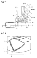
- This backward movement start position B is specifically illustrated in FIG. 7 .
- E1 and E2 represent boundary lines defined by the conditions J1 and J2 respectively.
- the center of the rear axle of the vehicle 1 is located within a region AR between the boundary lines E1 and E2, the vehicle 1 is at the backward movement start position B.
- condition J1 is defined on the basis of the center of the vehicle 1 and the center of the target parking space S.
- condition J1 may also be defined on the basis of an external portion of the vehicle 1 and an external portion (S2) of the target parking space S.
- condition J1 is replaced with the following condition J1A.
- the condition J1A is that the external portion of the vehicle 1 is not located in a turning outside region with respect to the external portion (S2) of the target parking space S if the vehicle 1 moves backwards at a maximum steering angle (i.e., with a minimum turning radius).
- the external portion of the vehicle 1 In moving backwards from the backward movement start position B with the minimum turning radius, the external portion of the vehicle 1 is located in a turning outside region with respect to the external portion of the target parking space S if the following relation is established.
- a condition satisfying the condition J1A is not the expression (1') but the following expression.
- the vehicle marks representing the contour of the overall external shape of the vehicle 1 are displayed as shown in FIG. 4 .
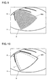
- FIG. 8 if faraway and nearby regions of a vehicle mark M1 are indicated by thin and thick lines respectively based on the law of perspective, it is easyto determinemore instinctivelywhether or not the estimated vehicle space is suitably positioned in relation to the target parking space S.
- a vehicle mark M2 in the form of a semitransparent plane indicating the shape of the vehicle 1 projected substantially onto a road surface can also be displayed as the estimated vehicle space. Because the vehicle mark M2 is semitransparent, parking boundary lines displayed on the display 4 to indicate the target parking space S do not disappear even if the vehicle mark M2 overlaps them, and it is possible to recognize the extent to which the vehicle mark M2 overlaps with the target parking space S.
- the vehicle mark M3 may be expressed as a vehicle mark representing the contour of the overall external shape of vehicle 1 as shown in FIG. 4 , a vehicle mark according to the law of perspective as shown in FIG. 8 , or a vehicle mark in the form of a semitransparent plane indicating the shape of the vehicle 1 projected substantially onto a road surface as shown in FIG. 9 .
- the wide vehicle mark M3 overlaps the parking boundary lines indicating the target parking space S, the use of a semitransparent vehicle mark is preferred.
- the estimated vehicle space such as the vehicle mark C2 is displayed at the position reached by the vehicle 1 after having moved backwards from the backward movement start position B at a constant steering angle while making a turn by a turning angle (90°- ⁇ ).
- a vehicle mark D2 may be displayed at a position obtained by displacing the position at which the vehicle mark C2 is displayed straight backwards by a predetermined distance D.
- a part of the vehicle mark D2 is located within the visible range of the camera 2. Therefore, a part of the vehicle mark D2 is displayed on the display 4 in a superimposed manner on the target parking space S, so it is easy to determine whether or not the vehicle 1 has become parallel to the target parking space S.
- a yaw angle of the vehicle 1 is calculated by integrating an angular speed of the vehicle 1 input from the yaw rate sensor 10 in the aforementioned embodiment, this is not obligatory.
- a distance sensor 14 instead of the yaw rate sensor 10 to calculate a yaw angle of the vehicle 1 based on a steering angle obtained from the steering angle sensor 9 and a moving distance of the vehicle 1 obtained from the distance sensor 14, and provide the driver with guiding information.
- the distance sensor 14 and the steering angle sensor 9 constitute the yaw angle detecting means.
- an operational switch 15 may be arranged near the driver seat and connected to the controller 8, and the angle of the estimated vehicle space displayed on the display 4 may be changed through operation of the operational switch 15.
- the turning angle in moving backwards from the backward movement start position B to the vehicle mark C is increased or reduced depending on the amount of change in the angle of the estimated vehicle space displayed on the display 4 and with respect to the angle (90°- ⁇ ) in the case where the vehicle 1 is perpendicular to the target parking space S. In this manner, more accurate parking guidance can be provided in accordance with the angle of the vehicle 1 at the initial stop position A.
- the lateral parking mode switch 12 may be thrown on the way that the vehicle 1 moves straight forwards toward the initial stop position A, and the controller 8 may recognize the initiation of parking guidance by detecting a change in the yaw angle of the vehicle 1 when the vehicle 1 moves forwards from the initial stop position A toward the backward movement start position B while making a turn with the steering wheel 7 being turned.
- a microphone and a voice recognition unit may be installed for issuing commands to the controller 8 by means of voice recognition.
- the controller 8 is not required to exist as a dedicated unit for parking assistance but may be incorporated into a navigation system or the like. This makes it possible not only to save the trouble of installing the controller 8 in the vehicle 1 but also to reduce the cost of the system for reasons of common use of a box-shaped body and sensor groups, the lack of the necessity to prepare wirings, and the like.
- lateral parking on the right side can also be performed in a similar manner.
- Guidance on the attainment of the backward movement start position B may be provided as soon as or some time after the vehicle 1 has entered the region AR.
- the initial stop position A is not limited to the position 0.5 to 1m apart from the entrance of the target parking space S.
- the region AR may be calculated according to an initial stop position A determined in advance.
- the vehicle 1 stops at the initial stop position A, it is not indispensable that the driver see the frame line S1 right beside the vehicle 1. For instance, the driver may see the frame line S2 right beside the vehicle 1. In this case, even if the steering angle in moving forwards while making a turn is small, the vehicle 1 can easily reach the region AR.
- the driver may view the center of the target parking space S right beside the vehicle 1. This is suited for the case of parking the vehicle in a parking lot with no parking frame.
- One of the aforementioned three states may be selected by a switch when the vehicle 1 is stopped at the initial stop position A.
- the process of parking can be initiated from an initial stop position A ensuring easier operation.
- the region AR is located above the boundary line E1 and on the right of the boundary line E3 in FIG. 7 .
- the backward movement start position B may not necessarily be calculated according to the yaw angle of the vehicle 1. It is also appropriate to store data on the region AR corresponding to the yaw angle in advance, and to determine, by referring to the data, whether or not the vehicle 1 has reached the backward movement start position B.
- the region AR may be calculated according to Xb, or data on the region AR corresponding to Xb may be stored in advance.
- the region AR may be calculated according to Yb or data on the region AR corresponding to Yb may be stored in advance.
- the present invention allows a vehicle to be guided to a backward movement start position where parking in a target parking space is possible, thereby making parking in the target parking space reliable and easy.
Landscapes
- Engineering & Computer Science (AREA)
- Chemical & Material Sciences (AREA)
- Combustion & Propulsion (AREA)
- Transportation (AREA)
- Mechanical Engineering (AREA)
- Steering Control In Accordance With Driving Conditions (AREA)
- Traffic Control Systems (AREA)
- Closed-Circuit Television Systems (AREA)
- Image Analysis (AREA)
- Image Processing (AREA)
- Catching Or Destruction (AREA)
Applications Claiming Priority (3)
| Application Number | Priority Date | Filing Date | Title |
|---|---|---|---|
| JP2004122880 | 2004-04-19 | ||
| JP2004160009A JP4466200B2 (ja) | 2004-04-19 | 2004-05-28 | 駐車支援装置 |
| PCT/JP2005/007363 WO2005102823A1 (en) | 2004-04-19 | 2005-04-12 | Parking assistance apparatus |
Publications (2)
| Publication Number | Publication Date |
|---|---|
| EP1737723A1 EP1737723A1 (en) | 2007-01-03 |
| EP1737723B1 true EP1737723B1 (en) | 2010-12-15 |
Family
ID=34964047
Family Applications (1)
| Application Number | Title | Priority Date | Filing Date |
|---|---|---|---|
| EP05729176A Active EP1737723B1 (en) | 2004-04-19 | 2005-04-12 | Parking assistance apparatus |
Country Status (9)
| Country | Link |
|---|---|
| US (1) | US7375651B2 (zh) |
| EP (1) | EP1737723B1 (zh) |
| JP (1) | JP4466200B2 (zh) |
| KR (1) | KR100754265B1 (zh) |
| AT (1) | ATE491621T1 (zh) |
| AU (1) | AU2005235040B2 (zh) |
| DE (1) | DE602005025330D1 (zh) |
| TW (1) | TWI265882B (zh) |
| WO (1) | WO2005102823A1 (zh) |
Families Citing this family (49)
| Publication number | Priority date | Publication date | Assignee | Title |
|---|---|---|---|---|
| US7251260B2 (en) * | 2004-08-24 | 2007-07-31 | Coherent, Inc. | Wavelength-locked fiber-coupled diode-laser bar |
| DE502005004318D1 (de) * | 2004-12-24 | 2008-07-10 | Continental Teves Ag & Co Ohg | Verfahren zum ermitteln der befahrbarkeit einer parklücke und einparkhilfe-einrichtung |
| JP4543983B2 (ja) * | 2005-03-22 | 2010-09-15 | 株式会社豊田自動織機 | 駐車支援装置 |
| DE102005044270A1 (de) * | 2005-09-16 | 2007-03-29 | Robert Bosch Gmbh | Verfahren und Vorrichtung zur Unterstützung eines Einparkvorgangs eines Fahrzeugs |
| JP4835109B2 (ja) * | 2005-10-31 | 2011-12-14 | アイシン精機株式会社 | 駐車目標位置設定装置 |
| JP4682809B2 (ja) * | 2005-11-04 | 2011-05-11 | 株式会社デンソー | 駐車支援システム |
| JP4414959B2 (ja) * | 2005-11-16 | 2010-02-17 | アイシン精機株式会社 | 駐車支援装置 |
| JP4742953B2 (ja) * | 2006-03-31 | 2011-08-10 | 株式会社デンソー | 画像処理装置,画像表示システムおよびプログラム |
| JP2007276590A (ja) * | 2006-04-05 | 2007-10-25 | Toyota Motor Corp | 駐車支援装置 |
| JP5309442B2 (ja) * | 2006-05-29 | 2013-10-09 | アイシン・エィ・ダブリュ株式会社 | 駐車支援方法及び駐車支援装置 |
| KR100764976B1 (ko) | 2006-09-19 | 2007-10-08 | 현대자동차주식회사 | 2점 지정을 통한 주차공간 설정방법 |
| JP5092330B2 (ja) * | 2006-09-27 | 2012-12-05 | アイシン・エィ・ダブリュ株式会社 | 駐車支援装置および駐車支援方法 |
| DE102006050550A1 (de) | 2006-10-26 | 2008-04-30 | Bayerische Motoren Werke Ag | Verfahren zur Steuerung eines Fahrmanövers |
| JP5115782B2 (ja) * | 2006-11-07 | 2013-01-09 | アイシン精機株式会社 | 駐車支援装置 |
| JP4853712B2 (ja) * | 2006-12-28 | 2012-01-11 | アイシン精機株式会社 | 駐車支援装置 |
| JP4858236B2 (ja) * | 2007-03-02 | 2012-01-18 | アイシン・エィ・ダブリュ株式会社 | 駐車支援方法及び駐車支援装置 |
| JP5105149B2 (ja) * | 2007-04-18 | 2012-12-19 | アイシン精機株式会社 | 駐車支援装置 |
| KR100974704B1 (ko) | 2007-04-30 | 2010-08-06 | 현대자동차주식회사 | 자동차의 주차 안내 방법 |
| US8050458B2 (en) * | 2007-06-18 | 2011-11-01 | Honda Elesys Co., Ltd. | Frontal view imaging and control device installed on movable object |
| JP2009019536A (ja) * | 2007-07-11 | 2009-01-29 | Omron Corp | 制御装置および方法 |
| KR100907702B1 (ko) * | 2007-10-23 | 2009-07-14 | 부산대학교 산학협력단 | 주차안내시스템 및 이를 이용한 주차안내방법 |
| JP4900232B2 (ja) | 2007-12-26 | 2012-03-21 | 日産自動車株式会社 | 車両用駐車支援装置および映像表示方法 |
| TWI399964B (zh) * | 2007-12-26 | 2013-06-21 | Chi Mei Comm Systems Inc | 手機停車預警系統及方法 |
| DE102008028763A1 (de) * | 2008-06-17 | 2009-12-24 | Valeo Schalter Und Sensoren Gmbh | Verfahren und Vorrichtung zur Unterstützung eines Einparkvorgangs eines Fahrzeugs |
| JP4661917B2 (ja) | 2008-07-25 | 2011-03-30 | 日産自動車株式会社 | 駐車支援装置および駐車支援方法 |
| CN101742250B (zh) * | 2008-11-21 | 2011-08-31 | 联创汽车电子有限公司 | 可视辅助泊车系统 |
| KR100993025B1 (ko) * | 2009-05-29 | 2010-11-09 | (주)엠지티글로벌 | 파킹 어시스턴트 장치 |
| JP5397321B2 (ja) * | 2009-06-09 | 2014-01-22 | 株式会社デンソー | 駐車支援システム |
| KR101043957B1 (ko) * | 2009-10-23 | 2011-06-24 | (주) 엔네비솔루션 | 주차 유도 방법 및 장치 |
| KR200456970Y1 (ko) | 2010-03-03 | 2011-11-30 | (주)칼전자 | 파킹 어시스턴트 장치 |
| DE102010010652A1 (de) | 2010-03-09 | 2011-09-15 | Valeo Schalter Und Sensoren Gmbh | Verfahren zum Unterstützen eines Fahrers beim Einparken eines Fahrzeugs in eine Querparklücke sowie Fahrerassistenzeinrichtung |
| DE102010020208A1 (de) * | 2010-05-12 | 2011-11-17 | Volkswagen Ag | Verfahren zum Einparken oder Ausparken eines Fahrzeugs sowie entsprechendes Assistenzsystem und Fahrzeug |
| US9007462B2 (en) * | 2010-06-18 | 2015-04-14 | Mitsubishi Electric Corporation | Driving assist apparatus, driving assist system, and driving assist camera unit |
| JP5454934B2 (ja) * | 2010-09-21 | 2014-03-26 | アイシン精機株式会社 | 運転支援装置 |
| CN102034366B (zh) * | 2010-12-17 | 2013-01-23 | 财团法人车辆研究测试中心 | 停车引导方法及装置 |
| WO2012104964A1 (ja) * | 2011-01-31 | 2012-08-09 | トヨタ自動車株式会社 | 車両制御装置 |
| DE102011010859B4 (de) * | 2011-02-10 | 2021-05-06 | Connaught Electronics Ltd. | Verfahren zum Betreiben eines Kamerasystems in einem Kraftfahrzeug, Kamerasystem und Kraftfahrzeug |
| JP2012232610A (ja) * | 2011-04-28 | 2012-11-29 | Toshiba Alpine Automotive Technology Corp | 駐車支援装置 |
| JP2012030796A (ja) * | 2011-11-14 | 2012-02-16 | Nissan Motor Co Ltd | 車両用駐車支援装置および映像表示方法 |
| US9399400B2 (en) * | 2012-11-27 | 2016-07-26 | Nissan Motor Co., Ltd. | Vehicular acceleration suppression device and vehicular acceleration suppression method |
| JP6024578B2 (ja) * | 2013-04-11 | 2016-11-16 | 株式会社Jvcケンウッド | 車載カメラシステムおよび車載カメラシステムにおける撮像方法 |
| KR102135900B1 (ko) * | 2013-11-29 | 2020-08-26 | 현대모비스(주) | 주차 보조 장치 및 방법 |
| DE112014005028A5 (de) * | 2013-12-23 | 2016-08-11 | Adc Automotive Distance Control Systems Gmbh | Park-Assistenzsystem und Verfahren zum Einparken eines Fahrzeuges in eine Parkgarage |
| DE102014202324A1 (de) * | 2014-02-10 | 2015-08-13 | Conti Temic Microelectronic Gmbh | Verfahren und Vorrichtung zum sicheren Parken eines Fahrzeugs |
| DE102015212689A1 (de) * | 2015-07-07 | 2017-01-12 | Robert Bosch Gmbh | Fahrerunabhängige Überführung eines Kraftfahrzeugs |
| KR101806619B1 (ko) * | 2015-09-21 | 2017-12-07 | 현대자동차주식회사 | 차량의 주차 안내 장치 및 방법 |
| KR101795151B1 (ko) * | 2015-10-05 | 2017-12-01 | 현대자동차주식회사 | 주차안내 장치 및 방법 |
| US10683035B2 (en) | 2015-12-08 | 2020-06-16 | Panasonic Intellectual Property Management Co., Ltd. | Parking assistance device, parking assistance method, and non-transitory computer readable medium |
| JP6958117B2 (ja) * | 2017-08-29 | 2021-11-02 | 株式会社アイシン | 駐車支援装置 |
Family Cites Families (16)
| Publication number | Priority date | Publication date | Assignee | Title |
|---|---|---|---|---|
| JPH01123844A (ja) * | 1987-11-06 | 1989-05-16 | Calp Corp | 耐熱容器 |
| JP3396893B2 (ja) | 1992-05-25 | 2003-04-14 | 株式会社デンソー | 車両の車庫誘導装置 |
| JP3575279B2 (ja) * | 1998-05-22 | 2004-10-13 | アイシン精機株式会社 | 駐車補助装置 |
| EP1050866B1 (en) * | 1999-04-28 | 2003-07-09 | Matsushita Electric Industrial Co., Ltd. | Parking assistance device and method |
| WO2001012472A1 (fr) | 1999-08-12 | 2001-02-22 | Kabushiki Kaisha Toyoda Jidoshokki Seisakusho | Dispositif d'assistance directionnelle |
| JP3508665B2 (ja) * | 1999-12-24 | 2004-03-22 | 株式会社豊田自動織機 | 操舵支援装置 |
| WO2001085496A1 (fr) * | 2000-05-12 | 2001-11-15 | Kabushiki Kaisha Toyota Jidoshokki | Appareil d'aide a la marche arriere d'un vehicule |
| EP1160146B2 (en) * | 2000-05-30 | 2013-07-24 | Aisin Seiki Kabushiki Kaisha | Parking assistive apparatus |
| JP3619753B2 (ja) * | 2000-07-03 | 2005-02-16 | トヨタ自動車株式会社 | 移動体の後方視界表示装置 |
| JP2002036991A (ja) * | 2000-07-27 | 2002-02-06 | Honda Motor Co Ltd | 駐車支援装置 |
| JP2002251632A (ja) | 2001-02-22 | 2002-09-06 | Matsushita Electric Ind Co Ltd | 運転支援装置 |
| JP3546863B2 (ja) * | 2001-06-22 | 2004-07-28 | 株式会社豊田自動織機 | 駐車支援装置 |
| JP4108314B2 (ja) * | 2001-10-31 | 2008-06-25 | トヨタ自動車株式会社 | 車両用周辺監視装置 |
| JP3729786B2 (ja) | 2002-01-10 | 2005-12-21 | トヨタ自動車株式会社 | 駐車支援装置 |
| JP3692082B2 (ja) | 2002-01-23 | 2005-09-07 | トヨタ自動車株式会社 | 駐車支援装置 |
| JP4234374B2 (ja) * | 2002-08-21 | 2009-03-04 | 三菱自動車工業株式会社 | 駐車支援装置 |
-
2004
- 2004-05-28 JP JP2004160009A patent/JP4466200B2/ja not_active Expired - Lifetime
-
2005
- 2005-04-12 KR KR1020057023553A patent/KR100754265B1/ko not_active IP Right Cessation
- 2005-04-12 WO PCT/JP2005/007363 patent/WO2005102823A1/en not_active Application Discontinuation
- 2005-04-12 DE DE602005025330T patent/DE602005025330D1/de active Active
- 2005-04-12 AU AU2005235040A patent/AU2005235040B2/en not_active Ceased
- 2005-04-12 EP EP05729176A patent/EP1737723B1/en active Active
- 2005-04-12 US US10/558,061 patent/US7375651B2/en not_active Expired - Fee Related
- 2005-04-12 AT AT05729176T patent/ATE491621T1/de not_active IP Right Cessation
- 2005-04-14 TW TW094111778A patent/TWI265882B/zh not_active IP Right Cessation
Also Published As
| Publication number | Publication date |
|---|---|
| WO2005102823A1 (en) | 2005-11-03 |
| JP4466200B2 (ja) | 2010-05-26 |
| KR20060018248A (ko) | 2006-02-28 |
| KR100754265B1 (ko) | 2007-09-03 |
| TWI265882B (en) | 2006-11-11 |
| EP1737723A1 (en) | 2007-01-03 |
| ATE491621T1 (de) | 2011-01-15 |
| US20070010918A1 (en) | 2007-01-11 |
| JP2005329915A (ja) | 2005-12-02 |
| TW200536735A (en) | 2005-11-16 |
| DE602005025330D1 (de) | 2011-01-27 |
| AU2005235040A1 (en) | 2005-11-03 |
| US7375651B2 (en) | 2008-05-20 |
| AU2005235040B2 (en) | 2007-12-06 |
Similar Documents
| Publication | Publication Date | Title |
|---|---|---|
| EP1737723B1 (en) | Parking assistance apparatus | |
| US7755511B2 (en) | Parking assistance apparatus | |
| EP1950097B1 (en) | Parking support device | |
| JP4161573B2 (ja) | 駐車支援装置 | |
| JP3183284B2 (ja) | 車両の後退時の操舵支援装置 | |
| EP1308346B1 (en) | Device for monitoring area around vehicle | |
| EP1468893B1 (en) | Parking assist apparatus and parking assist method for vehicle | |
| EP1332948B1 (en) | Parking assist device and method for assisting parking | |
| EP1215089B1 (en) | Parking aiding device | |
| US8958986B2 (en) | Parking assistance apparatus | |
| KR101806619B1 (ko) | 차량의 주차 안내 장치 및 방법 | |
| EP1442962A2 (en) | Parking assisting device | |
| EP2003021B1 (en) | Parking assistance device | |
| JP3687516B2 (ja) | 車両の後退時の操舵支援装置 | |
| JP4110937B2 (ja) | 駐車支援装置 | |
| JP4010247B2 (ja) | 駐車支援装置 | |
| JP2001322520A (ja) | 駐車支援装置 | |
| JP2009286376A (ja) | 駐車支援装置、駐車支援方法及びコンピュータプログラム | |
| JP2000118334A (ja) | 駐車支援装置 |
Legal Events
| Date | Code | Title | Description |
|---|---|---|---|
| PUAI | Public reference made under article 153(3) epc to a published international application that has entered the european phase |
Free format text: ORIGINAL CODE: 0009012 |
|
| 17P | Request for examination filed |
Effective date: 20051103 |
|
| AK | Designated contracting states |
Kind code of ref document: A1 Designated state(s): AT BE BG CH CY CZ DE DK EE ES FI FR GB GR HU IE IS IT LI LT LU MC NL PL PT RO SE SI SK TR |
|
| AX | Request for extension of the european patent |
Extension state: AL LV |
|
| 17Q | First examination report despatched |
Effective date: 20070301 |
|
| RAX | Requested extension states of the european patent have changed |
Extension state: LV Payment date: 20051103 Extension state: AL Payment date: 20051103 |
|
| GRAP | Despatch of communication of intention to grant a patent |
Free format text: ORIGINAL CODE: EPIDOSNIGR1 |
|
| GRAS | Grant fee paid |
Free format text: ORIGINAL CODE: EPIDOSNIGR3 |
|
| GRAA | (expected) grant |
Free format text: ORIGINAL CODE: 0009210 |
|
| AK | Designated contracting states |
Kind code of ref document: B1 Designated state(s): AT BE BG CH CY CZ DE DK EE ES FI FR GB GR HU IE IS IT LI LT LU MC NL PL PT RO SE SI SK TR |
|
| AX | Request for extension of the european patent |
Extension state: AL LV |
|
| REG | Reference to a national code |
Ref country code: CH Ref legal event code: EP Ref country code: GB Ref legal event code: FG4D |
|
| REG | Reference to a national code |
Ref country code: CH Ref legal event code: NV |
|
| REG | Reference to a national code |
Ref country code: IE Ref legal event code: FG4D |
|
| REF | Corresponds to: |
Ref document number: 602005025330 Country of ref document: DE Date of ref document: 20110127 Kind code of ref document: P |
|
| REG | Reference to a national code |
Ref country code: SE Ref legal event code: TRGR |
|
| REG | Reference to a national code |
Ref country code: NL Ref legal event code: VDEP Effective date: 20101215 |
|
| PG25 | Lapsed in a contracting state [announced via postgrant information from national office to epo] |
Ref country code: LT Free format text: LAPSE BECAUSE OF FAILURE TO SUBMIT A TRANSLATION OF THE DESCRIPTION OR TO PAY THE FEE WITHIN THE PRESCRIBED TIME-LIMIT Effective date: 20101215 |
|
| LTIE | Lt: invalidation of european patent or patent extension |
Effective date: 20101215 |
|
| PG25 | Lapsed in a contracting state [announced via postgrant information from national office to epo] |
Ref country code: FI Free format text: LAPSE BECAUSE OF FAILURE TO SUBMIT A TRANSLATION OF THE DESCRIPTION OR TO PAY THE FEE WITHIN THE PRESCRIBED TIME-LIMIT Effective date: 20101215 Ref country code: SI Free format text: LAPSE BECAUSE OF FAILURE TO SUBMIT A TRANSLATION OF THE DESCRIPTION OR TO PAY THE FEE WITHIN THE PRESCRIBED TIME-LIMIT Effective date: 20101215 Ref country code: CY Free format text: LAPSE BECAUSE OF FAILURE TO SUBMIT A TRANSLATION OF THE DESCRIPTION OR TO PAY THE FEE WITHIN THE PRESCRIBED TIME-LIMIT Effective date: 20101215 Ref country code: BG Free format text: LAPSE BECAUSE OF FAILURE TO SUBMIT A TRANSLATION OF THE DESCRIPTION OR TO PAY THE FEE WITHIN THE PRESCRIBED TIME-LIMIT Effective date: 20110315 Ref country code: AT Free format text: LAPSE BECAUSE OF FAILURE TO SUBMIT A TRANSLATION OF THE DESCRIPTION OR TO PAY THE FEE WITHIN THE PRESCRIBED TIME-LIMIT Effective date: 20101215 Ref country code: NL Free format text: LAPSE BECAUSE OF FAILURE TO SUBMIT A TRANSLATION OF THE DESCRIPTION OR TO PAY THE FEE WITHIN THE PRESCRIBED TIME-LIMIT Effective date: 20101215 |
|
| REG | Reference to a national code |
Ref country code: CH Ref legal event code: NV Representative=s name: NOVAGRAAF INTERNATIONAL SA Ref country code: CH Ref legal event code: PFA Owner name: KABUSHIKI KAISHA TOYOTA JIDOSHOKKI Free format text: KABUSHIKI KAISHA TOYOTA JIDOSHOKKI#2-1, TOYODA-CHO#KARIYA-SHI, AICHI 448-8671 (JP) -TRANSFER TO- KABUSHIKI KAISHA TOYOTA JIDOSHOKKI#2-1, TOYODA-CHO#KARIYA-SHI, AICHI 448-8671 (JP) |
|
| PG25 | Lapsed in a contracting state [announced via postgrant information from national office to epo] |
Ref country code: ES Free format text: LAPSE BECAUSE OF FAILURE TO SUBMIT A TRANSLATION OF THE DESCRIPTION OR TO PAY THE FEE WITHIN THE PRESCRIBED TIME-LIMIT Effective date: 20110326 Ref country code: CZ Free format text: LAPSE BECAUSE OF FAILURE TO SUBMIT A TRANSLATION OF THE DESCRIPTION OR TO PAY THE FEE WITHIN THE PRESCRIBED TIME-LIMIT Effective date: 20101215 Ref country code: IS Free format text: LAPSE BECAUSE OF FAILURE TO SUBMIT A TRANSLATION OF THE DESCRIPTION OR TO PAY THE FEE WITHIN THE PRESCRIBED TIME-LIMIT Effective date: 20110415 Ref country code: BE Free format text: LAPSE BECAUSE OF FAILURE TO SUBMIT A TRANSLATION OF THE DESCRIPTION OR TO PAY THE FEE WITHIN THE PRESCRIBED TIME-LIMIT Effective date: 20101215 Ref country code: GR Free format text: LAPSE BECAUSE OF FAILURE TO SUBMIT A TRANSLATION OF THE DESCRIPTION OR TO PAY THE FEE WITHIN THE PRESCRIBED TIME-LIMIT Effective date: 20110316 Ref country code: EE Free format text: LAPSE BECAUSE OF FAILURE TO SUBMIT A TRANSLATION OF THE DESCRIPTION OR TO PAY THE FEE WITHIN THE PRESCRIBED TIME-LIMIT Effective date: 20101215 Ref country code: PT Free format text: LAPSE BECAUSE OF FAILURE TO SUBMIT A TRANSLATION OF THE DESCRIPTION OR TO PAY THE FEE WITHIN THE PRESCRIBED TIME-LIMIT Effective date: 20110415 |
|
| PG25 | Lapsed in a contracting state [announced via postgrant information from national office to epo] |
Ref country code: SK Free format text: LAPSE BECAUSE OF FAILURE TO SUBMIT A TRANSLATION OF THE DESCRIPTION OR TO PAY THE FEE WITHIN THE PRESCRIBED TIME-LIMIT Effective date: 20101215 Ref country code: RO Free format text: LAPSE BECAUSE OF FAILURE TO SUBMIT A TRANSLATION OF THE DESCRIPTION OR TO PAY THE FEE WITHIN THE PRESCRIBED TIME-LIMIT Effective date: 20101215 Ref country code: PL Free format text: LAPSE BECAUSE OF FAILURE TO SUBMIT A TRANSLATION OF THE DESCRIPTION OR TO PAY THE FEE WITHIN THE PRESCRIBED TIME-LIMIT Effective date: 20101215 |
|
| PLBE | No opposition filed within time limit |
Free format text: ORIGINAL CODE: 0009261 |
|
| STAA | Information on the status of an ep patent application or granted ep patent |
Free format text: STATUS: NO OPPOSITION FILED WITHIN TIME LIMIT |
|
| PG25 | Lapsed in a contracting state [announced via postgrant information from national office to epo] |
Ref country code: DK Free format text: LAPSE BECAUSE OF FAILURE TO SUBMIT A TRANSLATION OF THE DESCRIPTION OR TO PAY THE FEE WITHIN THE PRESCRIBED TIME-LIMIT Effective date: 20101215 |
|
| 26N | No opposition filed |
Effective date: 20110916 |
|
| PG25 | Lapsed in a contracting state [announced via postgrant information from national office to epo] |
Ref country code: MC Free format text: LAPSE BECAUSE OF NON-PAYMENT OF DUE FEES Effective date: 20110430 |
|
| REG | Reference to a national code |
Ref country code: DE Ref legal event code: R097 Ref document number: 602005025330 Country of ref document: DE Effective date: 20110916 |
|
| REG | Reference to a national code |
Ref country code: IE Ref legal event code: MM4A |
|
| PG25 | Lapsed in a contracting state [announced via postgrant information from national office to epo] |
Ref country code: IE Free format text: LAPSE BECAUSE OF NON-PAYMENT OF DUE FEES Effective date: 20110412 |
|
| PGFP | Annual fee paid to national office [announced via postgrant information from national office to epo] |
Ref country code: DE Payment date: 20120425 Year of fee payment: 8 Ref country code: CH Payment date: 20120412 Year of fee payment: 8 |
|
| PGFP | Annual fee paid to national office [announced via postgrant information from national office to epo] |
Ref country code: GB Payment date: 20120411 Year of fee payment: 8 Ref country code: FR Payment date: 20120504 Year of fee payment: 8 Ref country code: SE Payment date: 20120411 Year of fee payment: 8 |
|
| PGFP | Annual fee paid to national office [announced via postgrant information from national office to epo] |
Ref country code: IT Payment date: 20120418 Year of fee payment: 8 |
|
| PG25 | Lapsed in a contracting state [announced via postgrant information from national office to epo] |
Ref country code: LU Free format text: LAPSE BECAUSE OF NON-PAYMENT OF DUE FEES Effective date: 20110412 |
|
| PG25 | Lapsed in a contracting state [announced via postgrant information from national office to epo] |
Ref country code: TR Free format text: LAPSE BECAUSE OF FAILURE TO SUBMIT A TRANSLATION OF THE DESCRIPTION OR TO PAY THE FEE WITHIN THE PRESCRIBED TIME-LIMIT Effective date: 20101215 |
|
| PG25 | Lapsed in a contracting state [announced via postgrant information from national office to epo] |
Ref country code: HU Free format text: LAPSE BECAUSE OF FAILURE TO SUBMIT A TRANSLATION OF THE DESCRIPTION OR TO PAY THE FEE WITHIN THE PRESCRIBED TIME-LIMIT Effective date: 20101215 |
|
| REG | Reference to a national code |
Ref country code: CH Ref legal event code: PL |
|
| REG | Reference to a national code |
Ref country code: SE Ref legal event code: EUG |
|
| GBPC | Gb: european patent ceased through non-payment of renewal fee |
Effective date: 20130412 |
|
| PG25 | Lapsed in a contracting state [announced via postgrant information from national office to epo] |
Ref country code: DE Free format text: LAPSE BECAUSE OF NON-PAYMENT OF DUE FEES Effective date: 20131101 Ref country code: LI Free format text: LAPSE BECAUSE OF NON-PAYMENT OF DUE FEES Effective date: 20130430 Ref country code: GB Free format text: LAPSE BECAUSE OF NON-PAYMENT OF DUE FEES Effective date: 20130412 Ref country code: CH Free format text: LAPSE BECAUSE OF NON-PAYMENT OF DUE FEES Effective date: 20130430 Ref country code: SE Free format text: LAPSE BECAUSE OF NON-PAYMENT OF DUE FEES Effective date: 20130413 |
|
| REG | Reference to a national code |
Ref country code: FR Ref legal event code: ST Effective date: 20131231 |
|
| REG | Reference to a national code |
Ref country code: DE Ref legal event code: R119 Ref document number: 602005025330 Country of ref document: DE Effective date: 20131101 |
|
| PG25 | Lapsed in a contracting state [announced via postgrant information from national office to epo] |
Ref country code: IT Free format text: LAPSE BECAUSE OF NON-PAYMENT OF DUE FEES Effective date: 20130412 Ref country code: FR Free format text: LAPSE BECAUSE OF NON-PAYMENT OF DUE FEES Effective date: 20130430 |