EP1737372B1 - Microscope chirurgical intégré et capteur à front d'ondes - Google Patents
Microscope chirurgical intégré et capteur à front d'ondes Download PDFInfo
- Publication number
- EP1737372B1 EP1737372B1 EP05737636.0A EP05737636A EP1737372B1 EP 1737372 B1 EP1737372 B1 EP 1737372B1 EP 05737636 A EP05737636 A EP 05737636A EP 1737372 B1 EP1737372 B1 EP 1737372B1
- Authority
- EP
- European Patent Office
- Prior art keywords
- eye
- wavefront sensor
- surgical
- microscope
- surgical microscope
- Prior art date
- Legal status (The legal status is an assumption and is not a legal conclusion. Google has not performed a legal analysis and makes no representation as to the accuracy of the status listed.)
- Active
Links
Images

Classifications
-
- A—HUMAN NECESSITIES
- A61—MEDICAL OR VETERINARY SCIENCE; HYGIENE
- A61B—DIAGNOSIS; SURGERY; IDENTIFICATION
- A61B3/00—Apparatus for testing the eyes; Instruments for examining the eyes
- A61B3/10—Objective types, i.e. instruments for examining the eyes independent of the patients' perceptions or reactions
- A61B3/103—Objective types, i.e. instruments for examining the eyes independent of the patients' perceptions or reactions for determining refraction, e.g. refractometers, skiascopes
-
- A—HUMAN NECESSITIES
- A61—MEDICAL OR VETERINARY SCIENCE; HYGIENE
- A61B—DIAGNOSIS; SURGERY; IDENTIFICATION
- A61B3/00—Apparatus for testing the eyes; Instruments for examining the eyes
- A61B3/10—Objective types, i.e. instruments for examining the eyes independent of the patients' perceptions or reactions
- A61B3/1015—Objective types, i.e. instruments for examining the eyes independent of the patients' perceptions or reactions for wavefront analysis
-
- A—HUMAN NECESSITIES
- A61—MEDICAL OR VETERINARY SCIENCE; HYGIENE
- A61B—DIAGNOSIS; SURGERY; IDENTIFICATION
- A61B3/00—Apparatus for testing the eyes; Instruments for examining the eyes
- A61B3/10—Objective types, i.e. instruments for examining the eyes independent of the patients' perceptions or reactions
- A61B3/13—Ophthalmic microscopes
-
- A—HUMAN NECESSITIES
- A61—MEDICAL OR VETERINARY SCIENCE; HYGIENE
- A61B—DIAGNOSIS; SURGERY; IDENTIFICATION
- A61B90/00—Instruments, implements or accessories specially adapted for surgery or diagnosis and not covered by any of the groups A61B1/00 - A61B50/00, e.g. for luxation treatment or for protecting wound edges
- A61B90/36—Image-producing devices or illumination devices not otherwise provided for
-
- A—HUMAN NECESSITIES
- A61—MEDICAL OR VETERINARY SCIENCE; HYGIENE
- A61F—FILTERS IMPLANTABLE INTO BLOOD VESSELS; PROSTHESES; DEVICES PROVIDING PATENCY TO, OR PREVENTING COLLAPSING OF, TUBULAR STRUCTURES OF THE BODY, e.g. STENTS; ORTHOPAEDIC, NURSING OR CONTRACEPTIVE DEVICES; FOMENTATION; TREATMENT OR PROTECTION OF EYES OR EARS; BANDAGES, DRESSINGS OR ABSORBENT PADS; FIRST-AID KITS
- A61F9/00—Methods or devices for treatment of the eyes; Devices for putting-in contact lenses; Devices to correct squinting; Apparatus to guide the blind; Protective devices for the eyes, carried on the body or in the hand
- A61F9/007—Methods or devices for eye surgery
- A61F9/008—Methods or devices for eye surgery using laser
- A61F9/00802—Methods or devices for eye surgery using laser for photoablation
- A61F9/0081—Transplantation
-
- A—HUMAN NECESSITIES
- A61—MEDICAL OR VETERINARY SCIENCE; HYGIENE
- A61F—FILTERS IMPLANTABLE INTO BLOOD VESSELS; PROSTHESES; DEVICES PROVIDING PATENCY TO, OR PREVENTING COLLAPSING OF, TUBULAR STRUCTURES OF THE BODY, e.g. STENTS; ORTHOPAEDIC, NURSING OR CONTRACEPTIVE DEVICES; FOMENTATION; TREATMENT OR PROTECTION OF EYES OR EARS; BANDAGES, DRESSINGS OR ABSORBENT PADS; FIRST-AID KITS
- A61F9/00—Methods or devices for treatment of the eyes; Devices for putting-in contact lenses; Devices to correct squinting; Apparatus to guide the blind; Protective devices for the eyes, carried on the body or in the hand
- A61F9/007—Methods or devices for eye surgery
- A61F9/008—Methods or devices for eye surgery using laser
- A61F9/00825—Methods or devices for eye surgery using laser for photodisruption
- A61F9/00827—Refractive correction, e.g. lenticle
-
- A—HUMAN NECESSITIES
- A61—MEDICAL OR VETERINARY SCIENCE; HYGIENE
- A61F—FILTERS IMPLANTABLE INTO BLOOD VESSELS; PROSTHESES; DEVICES PROVIDING PATENCY TO, OR PREVENTING COLLAPSING OF, TUBULAR STRUCTURES OF THE BODY, e.g. STENTS; ORTHOPAEDIC, NURSING OR CONTRACEPTIVE DEVICES; FOMENTATION; TREATMENT OR PROTECTION OF EYES OR EARS; BANDAGES, DRESSINGS OR ABSORBENT PADS; FIRST-AID KITS
- A61F9/00—Methods or devices for treatment of the eyes; Devices for putting-in contact lenses; Devices to correct squinting; Apparatus to guide the blind; Protective devices for the eyes, carried on the body or in the hand
- A61F9/007—Methods or devices for eye surgery
- A61F9/013—Instruments for compensation of ocular refraction ; Instruments for use in cornea removal, for reshaping or performing incisions in the cornea
-
- A—HUMAN NECESSITIES
- A61—MEDICAL OR VETERINARY SCIENCE; HYGIENE
- A61B—DIAGNOSIS; SURGERY; IDENTIFICATION
- A61B90/00—Instruments, implements or accessories specially adapted for surgery or diagnosis and not covered by any of the groups A61B1/00 - A61B50/00, e.g. for luxation treatment or for protecting wound edges
- A61B90/20—Surgical microscopes characterised by non-optical aspects
-
- A—HUMAN NECESSITIES
- A61—MEDICAL OR VETERINARY SCIENCE; HYGIENE
- A61F—FILTERS IMPLANTABLE INTO BLOOD VESSELS; PROSTHESES; DEVICES PROVIDING PATENCY TO, OR PREVENTING COLLAPSING OF, TUBULAR STRUCTURES OF THE BODY, e.g. STENTS; ORTHOPAEDIC, NURSING OR CONTRACEPTIVE DEVICES; FOMENTATION; TREATMENT OR PROTECTION OF EYES OR EARS; BANDAGES, DRESSINGS OR ABSORBENT PADS; FIRST-AID KITS
- A61F9/00—Methods or devices for treatment of the eyes; Devices for putting-in contact lenses; Devices to correct squinting; Apparatus to guide the blind; Protective devices for the eyes, carried on the body or in the hand
- A61F9/007—Methods or devices for eye surgery
- A61F9/008—Methods or devices for eye surgery using laser
- A61F2009/00842—Permanent Structural Change [PSC] in index of refraction; Limit between ablation and plasma ignition
-
- A—HUMAN NECESSITIES
- A61—MEDICAL OR VETERINARY SCIENCE; HYGIENE
- A61F—FILTERS IMPLANTABLE INTO BLOOD VESSELS; PROSTHESES; DEVICES PROVIDING PATENCY TO, OR PREVENTING COLLAPSING OF, TUBULAR STRUCTURES OF THE BODY, e.g. STENTS; ORTHOPAEDIC, NURSING OR CONTRACEPTIVE DEVICES; FOMENTATION; TREATMENT OR PROTECTION OF EYES OR EARS; BANDAGES, DRESSINGS OR ABSORBENT PADS; FIRST-AID KITS
- A61F9/00—Methods or devices for treatment of the eyes; Devices for putting-in contact lenses; Devices to correct squinting; Apparatus to guide the blind; Protective devices for the eyes, carried on the body or in the hand
- A61F9/007—Methods or devices for eye surgery
- A61F9/008—Methods or devices for eye surgery using laser
- A61F2009/00844—Feedback systems
- A61F2009/00848—Feedback systems based on wavefront
-
- A—HUMAN NECESSITIES
- A61—MEDICAL OR VETERINARY SCIENCE; HYGIENE
- A61F—FILTERS IMPLANTABLE INTO BLOOD VESSELS; PROSTHESES; DEVICES PROVIDING PATENCY TO, OR PREVENTING COLLAPSING OF, TUBULAR STRUCTURES OF THE BODY, e.g. STENTS; ORTHOPAEDIC, NURSING OR CONTRACEPTIVE DEVICES; FOMENTATION; TREATMENT OR PROTECTION OF EYES OR EARS; BANDAGES, DRESSINGS OR ABSORBENT PADS; FIRST-AID KITS
- A61F9/00—Methods or devices for treatment of the eyes; Devices for putting-in contact lenses; Devices to correct squinting; Apparatus to guide the blind; Protective devices for the eyes, carried on the body or in the hand
- A61F9/007—Methods or devices for eye surgery
- A61F9/008—Methods or devices for eye surgery using laser
- A61F2009/00853—Laser thermal keratoplasty or radial keratotomy
-
- A—HUMAN NECESSITIES
- A61—MEDICAL OR VETERINARY SCIENCE; HYGIENE
- A61F—FILTERS IMPLANTABLE INTO BLOOD VESSELS; PROSTHESES; DEVICES PROVIDING PATENCY TO, OR PREVENTING COLLAPSING OF, TUBULAR STRUCTURES OF THE BODY, e.g. STENTS; ORTHOPAEDIC, NURSING OR CONTRACEPTIVE DEVICES; FOMENTATION; TREATMENT OR PROTECTION OF EYES OR EARS; BANDAGES, DRESSINGS OR ABSORBENT PADS; FIRST-AID KITS
- A61F9/00—Methods or devices for treatment of the eyes; Devices for putting-in contact lenses; Devices to correct squinting; Apparatus to guide the blind; Protective devices for the eyes, carried on the body or in the hand
- A61F9/007—Methods or devices for eye surgery
- A61F9/008—Methods or devices for eye surgery using laser
- A61F2009/00861—Methods or devices for eye surgery using laser adapted for treatment at a particular location
- A61F2009/00868—Ciliary muscles or trabecular meshwork
-
- A—HUMAN NECESSITIES
- A61—MEDICAL OR VETERINARY SCIENCE; HYGIENE
- A61F—FILTERS IMPLANTABLE INTO BLOOD VESSELS; PROSTHESES; DEVICES PROVIDING PATENCY TO, OR PREVENTING COLLAPSING OF, TUBULAR STRUCTURES OF THE BODY, e.g. STENTS; ORTHOPAEDIC, NURSING OR CONTRACEPTIVE DEVICES; FOMENTATION; TREATMENT OR PROTECTION OF EYES OR EARS; BANDAGES, DRESSINGS OR ABSORBENT PADS; FIRST-AID KITS
- A61F9/00—Methods or devices for treatment of the eyes; Devices for putting-in contact lenses; Devices to correct squinting; Apparatus to guide the blind; Protective devices for the eyes, carried on the body or in the hand
- A61F9/007—Methods or devices for eye surgery
- A61F9/008—Methods or devices for eye surgery using laser
- A61F2009/00861—Methods or devices for eye surgery using laser adapted for treatment at a particular location
- A61F2009/00872—Cornea
-
- A—HUMAN NECESSITIES
- A61—MEDICAL OR VETERINARY SCIENCE; HYGIENE
- A61F—FILTERS IMPLANTABLE INTO BLOOD VESSELS; PROSTHESES; DEVICES PROVIDING PATENCY TO, OR PREVENTING COLLAPSING OF, TUBULAR STRUCTURES OF THE BODY, e.g. STENTS; ORTHOPAEDIC, NURSING OR CONTRACEPTIVE DEVICES; FOMENTATION; TREATMENT OR PROTECTION OF EYES OR EARS; BANDAGES, DRESSINGS OR ABSORBENT PADS; FIRST-AID KITS
- A61F9/00—Methods or devices for treatment of the eyes; Devices for putting-in contact lenses; Devices to correct squinting; Apparatus to guide the blind; Protective devices for the eyes, carried on the body or in the hand
- A61F9/007—Methods or devices for eye surgery
- A61F9/008—Methods or devices for eye surgery using laser
- A61F2009/00885—Methods or devices for eye surgery using laser for treating a particular disease
- A61F2009/00887—Cataract
-
- A—HUMAN NECESSITIES
- A61—MEDICAL OR VETERINARY SCIENCE; HYGIENE
- A61F—FILTERS IMPLANTABLE INTO BLOOD VESSELS; PROSTHESES; DEVICES PROVIDING PATENCY TO, OR PREVENTING COLLAPSING OF, TUBULAR STRUCTURES OF THE BODY, e.g. STENTS; ORTHOPAEDIC, NURSING OR CONTRACEPTIVE DEVICES; FOMENTATION; TREATMENT OR PROTECTION OF EYES OR EARS; BANDAGES, DRESSINGS OR ABSORBENT PADS; FIRST-AID KITS
- A61F9/00—Methods or devices for treatment of the eyes; Devices for putting-in contact lenses; Devices to correct squinting; Apparatus to guide the blind; Protective devices for the eyes, carried on the body or in the hand
- A61F9/007—Methods or devices for eye surgery
- A61F9/00736—Instruments for removal of intra-ocular material or intra-ocular injection, e.g. cataract instruments
-
- A—HUMAN NECESSITIES
- A61—MEDICAL OR VETERINARY SCIENCE; HYGIENE
- A61F—FILTERS IMPLANTABLE INTO BLOOD VESSELS; PROSTHESES; DEVICES PROVIDING PATENCY TO, OR PREVENTING COLLAPSING OF, TUBULAR STRUCTURES OF THE BODY, e.g. STENTS; ORTHOPAEDIC, NURSING OR CONTRACEPTIVE DEVICES; FOMENTATION; TREATMENT OR PROTECTION OF EYES OR EARS; BANDAGES, DRESSINGS OR ABSORBENT PADS; FIRST-AID KITS
- A61F9/00—Methods or devices for treatment of the eyes; Devices for putting-in contact lenses; Devices to correct squinting; Apparatus to guide the blind; Protective devices for the eyes, carried on the body or in the hand
- A61F9/007—Methods or devices for eye surgery
- A61F9/008—Methods or devices for eye surgery using laser
- A61F9/00825—Methods or devices for eye surgery using laser for photodisruption
- A61F9/00831—Transplantation
-
- A—HUMAN NECESSITIES
- A61—MEDICAL OR VETERINARY SCIENCE; HYGIENE
- A61F—FILTERS IMPLANTABLE INTO BLOOD VESSELS; PROSTHESES; DEVICES PROVIDING PATENCY TO, OR PREVENTING COLLAPSING OF, TUBULAR STRUCTURES OF THE BODY, e.g. STENTS; ORTHOPAEDIC, NURSING OR CONTRACEPTIVE DEVICES; FOMENTATION; TREATMENT OR PROTECTION OF EYES OR EARS; BANDAGES, DRESSINGS OR ABSORBENT PADS; FIRST-AID KITS
- A61F9/00—Methods or devices for treatment of the eyes; Devices for putting-in contact lenses; Devices to correct squinting; Apparatus to guide the blind; Protective devices for the eyes, carried on the body or in the hand
- A61F9/007—Methods or devices for eye surgery
- A61F9/008—Methods or devices for eye surgery using laser
- A61F9/00825—Methods or devices for eye surgery using laser for photodisruption
- A61F9/00834—Inlays; Onlays; Intraocular lenses [IOL]
Definitions
- Refractive surgery and other corrective procedures are commonly performed on the human eye.
- the refractive quality of the eye is altered.
- the goal of refractive surgery typically is to correct a defective refractive condition of the eye, while not diminishing the overall refractive quality of the eye. In some cases, the goal is to actually improve the overall refractive quality of the eye.
- Wavefront sensors generally provide the greatest detail about the refractive condition of, and additional information relating to, the eye. Wavefront sensors are generally standalone devices that operate in relatively large areas dedicated to the use of the wavefront sensors. With most existing wavefront sensors, the patient's eye is measured while the patient is in a sitting position.
- measuring the refractive quality of the eye after the refractive surgery has been performed provides a quantification of the outcome of the surgery, it does not allow modifications to the surgery to be performed while the patient remains in the surgical position. If the outcome is not ideal, the patient may be relocated to the surgical area for a re-treatment, but in many cases a re-treatment may not be as effective as if the procedure had been performed to produce an ideal result the first time before the patient was moved from the surgical position. Additionally, moving a patient out of the sterile surgical field for diagnostic purposes, and then back into the surgical field, can be problematic.
- the surgeon would have the opportunity to judge whether the procedure was producing desired results at the expected rate, and would be able to make adjustments or course corrections to the procedure midstream to improve the likelihood of achieving the desired outcome.
- existing wavefront sensors and other measuring devices are generally relatively large and heavy, making them impracticable or impossible to suspend above a patient's head during surgery. As a result, a patient must be physically moved between wavefront measurement procedures and surgical correction procedures that are typically performed under a surgical microscope.
- WO 2004/093663 A discloses a surgical device for measuring properties of an eye, comprising: a surgical microscope providing a first field of view; and a wavefront sensor optically aligned with the surgical microscope and providing a second field of view, wherein the first field of view at least partially overlaps the second field of view.
- a surgical device for measuring properties of an eye as claimed in claim 1 is provided.
- the dependent claims show some examples of such a surgical device.
- a wavefront sensor is integrated with a surgical microscope for allowing a doctor to make repeated measurements of a patient's eye while the patient remains in a surgical position.
- the device includes a wavefront sensor optically aligned with a surgical microscope such that their fields of view at least partially overlap.
- the optional inclusion of lightweight, compact diffractive optical components in the wavefront sensor allows the integrated device to be supported on a balancing mechanism above a patient's head during a surgical procedure. As a result, the need to reposition the device and/or the patient between measuring optical properties of the eye and performing surgical procedures on the eye is eliminated.
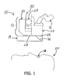
- a surgical device 10 includes a surgical microscope 12, or other suitable viewing device, attached to a wavefront sensor 14, or other measuring device.
- the surgical microscope 12 includes an eyepiece 16, or other viewing mechanism, which includes one or more optical channels each having one or more optical lenses therein.
- the eyepiece 16 is preferably binocular, or stereo, in that it includes two optical channels for allowing a doctor to view an eye 18 of a patient 20 using both of the doctor's eyes (as is best seen in Fig. 5 ). While a monocular eyepiece may alternatively be used, a binocular eyepiece is generally preferred because it provides a higher quality, more complete view to the doctor.
- the surgical microscope 12 preferably further includes a light source 22 for providing visible light into the optical pathway of the eyepiece 16, a focusing knob 24 for adjusting the focus of the microscope 12, and an objective lens 26, or other suitable lens, for focusing light beams.
- the objective lens 26 is threaded onto the microscope 12 via internal threads on the lens 26 that match external threads on a body 25 of the microscope 12.
- the wavefront sensor 14 may be attached to the microscope 12 in any suitable manner, and is preferably removably attached to the microscope 12.
- the objective lens 26 may be removed from the microscope 12, and the wavefront sensor 14, which preferably includes an attachment portion with interior threads that match the exterior threads of the microscope body 25, may be screwed onto the external threads of the microscope 12. The objective lens 26 may then be screwed back onto the external threads beneath the attachment portion of the wavefront sensor 14.
- One or more fasteners 28 may optionally be included to further (or alternatively) secure the wavefront sensor 14 to the microscope 12.
- the wavefront sensor 14 may alternatively be attached to the microscope via screws, bolts, pins, clamps, adhesive, or any other suitable fasteners or attachment means.
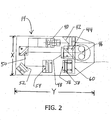
- the wavefront sensor 14 includes a laser source 40, or other light source, for creating a beam of light, preferably infrared light.
- the beam of infrared light is preferably directed by a mirror 42 toward a beam splitter 44 or other suitable device.
- An aperture-sharing element such as a combiner mirror 46 (shown in dashed lines in Fig. 1 ), a beam-splitter, or other similar device, reflects the beam of infrared light down into the eye 18 of the patient 20.
- the combiner mirror 46 preferably reflects infrared light while transmitting visible light so that a doctor can see the patient's eye 18 while looking through the combiner mirror 46.
- the combiner mirror 46 may alternatively be configured to reflect a portion of the visible light spectrum, and/or to transmit a portion of the infrared light spectrum, as described below.
- the infrared light beam After the infrared light beam enters the eye 18, it is reflected, as a wavefront, from the retina of the eye 18 toward the combiner mirror 46.
- the combiner mirror 46 redirects the light beam through the beam splitter 44 toward a first lens 48.
- the first lens 48 relays the infrared light beam off of mirrors 50 and 52 toward a second lens 54, which directs the light beam onto a diffractive optical component, such as a first reticle or grating 56.
- the mirrors 42, 50, 52 are optionally included in the wavefront sensor 14 for re-directing the light beam to maintain it within a compact area, which facilitates the minimization of the overall size and length of the wavefront sensor 14. A greater or lesser number of mirrors may be included in the wavefront sensor 14.
- the light beam is diffracted by the first grating 56, as described in detail below, and preferably travels through another diffractive optical component, such as a second grating 58, which further diffracts the light beam and creates a final image of the wavefront reflected from the eye 18.
- a camera 60 and/or another light detector or sensor, such as a CCD camera or other suitable device, then captures, records, and/or detects the final image of the eye 18 and converts it into a computer-readable format.
- a computer may then measure and analyze the data to quantify characteristics of the wavefront, and thus, the refractive properties of the eye being examined.
- the wavefront sensor 14 may of course include a greater or lesser number of components to meet the requirements of a given system. For example, a greater or lesser number of diffractive gratings or optical lenses may be included in the wavefront sensor 14. Moreover, additional optical components, such as a camera lens, may optionally be included between the second refractive grating 58 and the camera 60. Thus, the specific configuration of the wavefront sensor 14 illustrated in Fig. 2 is only one example a suitable wavefront sensor configuration.
- the wavefront sensor 14 may be very compact and lightweight, and can produce higher resolution and more accurate alignment registration than a wavefront sensor using larger conventional refractive optics, such as a typical Hartmann-Shack wavefront sensor, as described below.
- the wavefront sensor 14 preferably has a length Y that is less than 10 inches, more preferably less than nine inches, more preferably approximately 8.5 inches, and a width X that is preferably less than 5 inches, more preferably approximately 4.5 inches.
- the wavefront sensor 14 preferably weighs less than five pounds, more preferably less than 3 pounds or less than 2 pounds.
- the wavefront sensor 14 may of course be any other suitable size and/or weight.
- the wavefront sensor 14 may be directly or indirectly attached to the surgical microscope 12 to form an integrated surgical device 10.
- integrated generally refers to the wavefront sensor 14 and the surgical microscope 12 being incorporated into a unit.
- the integrated surgical device 10 may be attached to a balancing mechanism, hanging mechanism, or other suitable device or stand for suspending the integrated device 10 over a patient's head during surgery.
- the balancing mechanism or other supporting device may be spring-loaded, counter-balanced, or otherwise balanced for supporting the integrated device 10. Balancing mechanisms of this nature are commonly used to support and suspend surgical microscopes.
- an attachment portion 30 of the surgical microscope 12 may be attached to the balancing mechanism via screws, pins, bolts, or other suitable fasteners, or the integrated device 10 may be attached to the balancing mechanism in any other suitable manner.
- the wavefront sensor 14 may be added to an existing surgical microscope 12 that is already supported on a balancing mechanism. The field of view and the focal length of the microscope 12 and/or the wavefront sensor 14 may then be adjusted, if necessary, to optically align the devices relative to one another, as further described below.
- refractive optical components are used to redirect a light beam as it passes through a material having a higher density than air, such as a glass refractive lens.
- Diffractive optical components conversely, are used to bend a light beam as it encounters the sharp edges of an element, such as the gratings 56, 58, and only portions of the light beam occurring near the edges of the grating or other object are redirected.
- Diffractive optical components, such as gratings are typically significantly smaller and weigh less than refractive optical components, such as refractive lenses.
- the one or more diffractive gratings used in the wavefront sensor 14 may be made of any suitable material.
- a preferred diffractive grating is made from a clear material, such as glass, and has equally spaced perpendicular lines etched or otherwise present on its surface.
- the grating may include, for example, a repeating sequence of solid lines each having a width of approximately 12.5 microns, with each pair of lines separated by approximately 12.5 microns of clear glass (the lines and glass spaces on the grating may of course have any other suitable dimensions). The same sequence is repeated with lines running perpendicularly to the first set of lines, such that a pattern similar to that of a standard grid (i.e., a network of uniformly spaced horizontal and perpendicular lines) is formed.
- a standard grid i.e., a network of uniformly spaced horizontal and perpendicular lines
- a wavefront of light reflected from an eye encounters a grating (referred to as the "Periodic Object" in Fig. 3 ) diffractive effects begin to occur.
- Some of the light hits the solid portions of the lines on the grating and is prevented from passing through the grating. Some of the light passes cleanly through the clear spaces in the grating and is not affected by the grating lines. The remaining light, however, encounters the edges of the solid lines as it passes through the grating. This light is disturbed by the lines and is deflected away from the central core of the light that passes cleanly through the clear spaces in the grating.
- This redirected light encounters light that has been redirected by one or more adjacent grating lines.
- Talbot Effect a phenomenon known as the "Talbot Effect” occurs, and a series of dark and light zones form in a space within a predictable distance downstream from the grating, at locations referred to as Talbot planes.
- This phenomenon is described in detail in U.S. Patent Application Serial No. 10/885,504, filed July 6, 2004 , as well as in " Fourier Transform Method For Automatic Processing of Moiré Deflectograms," Quiroga et al., Opt. Eng. 38(6) pp.
- the wavefront of light that passed through the grating is a flat, plane wave
- the dark and light zones form a perfect replica of the grating, i.e., a virtual image of the grating.
- the shape and size of the virtual image of the grating is distorted, as shown in Fig. 3 .
- the virtual image may be observed by a camera or other light detector, and the images may be measured, typically by a computer, to accurately quantify the characteristics of the wavefront, and hence, the refractive properties of the eye being examined.
- two or more gratings are aligned in series in the wavefront sensor.
- the virtual image of the grating is modified to show less resolution, which can compensate for a camera having insufficient resolution.
- the changes in the virtual image of the initial grating are visually converted into rotational movement, rather than just shrinkage or expansion, and the characteristics of the wavefront may be determined without change in size of the virtual image.
- the virtual image created by the gratings contains, simultaneously, two sets of information.
- the first set of information is the virtual image of the grating from which the refractive properties of the eye are characterized, as described above.
- the second set of information is an almost complete image of the pupil of the eye, which is comprised of the light that passed untouched through the clear spaces of the grating, as well as light that reflected from the surface of the pupil, the sclera, the limbus, and/or other features of the eye if additional illumination is directed to illuminate these features.
- This image essentially appears to be that of an eye being observed with a grid (i.e., a network of uniformly spaced horizontal and perpendicular lines) between the eye and the observer.
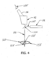
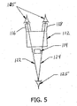
- FIG. 4 and 5 a schematic representation of a process for measuring characteristics of an eye is shown.
- a surgeon (or other doctor) 105 looks through a surgical microscope 112 at the eye 125 of a patient.
- the surgical microscope 112 preferably includes binocular, or stereo, optics such that it includes two optical viewing channels 116, 118 (as shown in Fig. 5 ).
- a monocular microscope may alternatively be used, however. Visible light reflecting from the patient's eye 125 travels along a light pathway 150, passes through a combiner mirror 120 or similar device, and into the microscope 112, so that the surgeon may view the patient's eye 125 along visual pathways 122, 124.
- a wavefront sensor 114 generates an infrared light beam and projects it outwardly along a pathway 145 toward the combiner mirror 120. While the combiner mirror 120 is shown located outside of the wavefront sensor 114 in the schematic representation of Figs. 4 and 5 , it is understood that the combiner mirror 120 may be located inside the wavefront sensor 114, as is shown in Figs. 1 and 2 , or in any other suitable location where the optical pathways of the surgical microscope 112 and the wavefront sensor 114 meet.
- the combiner mirror 120 is preferably transparent to visible light but reflective to infrared light so that it reflects the infrared light beam toward the patient's eye 125.
- the wavefront sensor 114 and the microscope 112 preferably share a common aperture through the combiner mirror 120.
- a beam splitter that transmits and reflects both a portion of the visible light and a portion of the infrared light may be used in place of the combiner mirror 120. Using such a beam splitter would allow the wavefront sensor 114 to operate at a wavelength other than that of the infrared light, such as at a wavelength in the visible spectrum.
- the combiner mirror 120 may be configured to reflect a portion of the visible light spectrum, allowing the wavefront sensor 114 to operate in a wavelength range within the visible spectrum, yet prevent that particular wavelength from entering the microscope 112.
- the combiner mirror 120 may be a narrow pass/reflect combiner, which reflects only a defined wavelength of light having a lower and upper range, thereby allowing the wavefront sensor 114 to operate within the visible light spectrum. The defined visible light spectrum would then be selectively blocked from returning to the microscope 112, while all light above or below the lower and upper ranges would be freely transmitted.
- the combiner mirror 120 reflects the light beam along pathway 150 toward the patient's eye 125.
- the infrared light enters the patient's eye 125 and is reflected as a wavefront back along light pathway 150 toward the combiner mirror 120, which reflects the wavefront along light pathway 145 into the wavefront sensor 114.
- the wavefront sensor 114 measures the wavefront using the process described above, or using a similar process.
- the wavefront sensor 114 may have the same configuration and components as the wavefront sensor 14 illustrated in Fig. 2 , or it may have an alternative configuration and may include alternative components.
- the wavefront sensor 114 and the microscope 112 are each preferably focused at a point occurring at plane 135, such that a field of view 155 of the wavefront sensor 114 at least partially overlaps a field of 160 of the microscope 112.
- the patient's eye 125 is preferably located within the overlapping portion of the fields of view 155, 160.
- the wavefront sensor 114 and the microscope 112 are focused at substantially the same point, such that the center of each field of view 155, 160 is located at approximately the same point, in the same plane 135, preferably at or near the center of the patient's eye 125.
- the surgeon 105 may look through the microscope 112 directly into the visual axis of the patient's eye 125 while the wavefront sensor 114 takes measurements of the eye 125. Furthermore, because the fields of view 155, 160 overlap at the patient's eye 125, the patient does not have to change the gaze angle of the patient's eye 125 at any time during the viewing and measurement processes. This can be very advantageous, especially when the surgical procedure being performed prevents the patient from seeing clearly, or at all, such that it is nearly impossible for the patient to accurately adjust the gaze angle of the patient's eye 125 according to a surgeon's instructions.
- the integrated wavefront sensor and surgical microscope described herein provides several advantages. First, it allows a surgeon or other doctor to directly view a patient's eye while the wavefront sensor performs measurements of the refractive characteristics or other optical properties of the patient's eye. As a result, a surgeon can view the results of a given step of a surgical procedure without having to move the patient, the patient's eye, or the device. Indeed, the gaze angle of the patient's eye does not need to change at all during the viewing and measuring steps, and the surgeon's view may be directly aligned with, as opposed to offset from, the visual axis of the patient's eye.
- the integrated device may be very compact. Accordingly, the lightweight integrated device can be suspended on a balancing device, or other supporting mechanism, above the head of a patient lying in the supine surgical position, while the surgeon views the patient's eye through the surgical microscope of the integrated device.
- the integrated surgical device 10 is preferably not integrated with or otherwise attached to a refractive laser device or other refractive surgical tool.
- the integrated surgical device 10 is preferably used primarily for viewing and measuring purposes, while one or more surgical tools used to perform corrective eye procedures are physically separate from the integrated device. Lightweight or otherwise compact surgical tools, however, may optionally be incorporated into the surgical device 10.
- the wavefront sensor 14 and the surgical microscope 12 also preferably do not share an optical pathway to the patient's eye 18 with any other surgical devices.
- the wavefront sensor and the surgical microscope are preferably (although, not necessarily) separate components that are removably attached to one another, they may each include their own optical components, including any lenses. Thus, the wavefront sensor and the surgical microscope do not need to share a lens, thus providing several advantages and general design flexibility over integrated surgical systems that require one or more lenses to be shared between two or more optical components.
- Some surgical systems for example, use a common optical lens to focus light beams from both a wavefront sensor and a refractive laser device.
- a common optical lens By sharing a lens in this manner, the flexibility to select or design the lens for only a single specific function is lost, as is the ability to design the best possible lens for the overall system application.
- compromises must be made to meet the requirements of each component that shares the lens.
- Antireflective coatings are commonly applied to lenses so that they can function optimally within a certain wavelength. If the laser being used is of a different wavelength than the wavefront sensor illumination beam, however, a common antireflective coating cannot be selected that will work optimally for each of the wavelengths. The same holds true for the wavelength of the wavefront sensor illumination beam in comparison to that of the visible light used to provide visibility through a microscope. Because the surgical device 10 described herein does not require that a lens be shared between the wavefront sensor and the surgical microscope, different antireflective coatings may be applied to the lenses of each of these components, thus allowing for optimal coatings to be selected for each component.
- Another disadvantage of sharing a common lens between two or more optical components is the inability to select an optimal focal length, or power, of the lens for each component involved.
- a long focal length lens is desirable in a wavefront sensor to provide sufficient working space for a doctor between the wavefront sensor and the patient.
- a shorter focal length lens is desirable to more tightly focus the laser energy into a shorter plane.
- a system that shares a common lens for these components must compromise or settle on a common focal length, which will not be optimal for one or both of the components.
- an advantageous feature of the surgical device 10 is that it does not require a lens to be shared by the wavefront sensor 14 and the surgical microscope 12.
- the surgical device 10 may be used to improve and/or enhance a variety of corrective procedures performed on the eye.
- corrective eye procedures may be enhanced by using the surgical device 10 .
- Cataract surgery generally involves replacing the natural lens of an eye after the natural lens has become unclear.
- Existing methods typically require measuring the physical dimensions of the eye with ultrasound, followed by calculating the refractive power of the artificial lens, or other replacement lens, to be inserted. Because the natural lens is unclear, these measurements are often difficult to make. Additionally, variations in the structures of the eye that cannot typically be measured using existing techniques may degrade the calculation.
- the integrated surgical device 10 facilitates measurement of the eye's refractive power before and/or immediately after the natural lens is removed, without movement of the patient or the patient's eye, such that the true refractive power of the eye can be more accurately determined. For example, if it is determined that 42 diopters of power are needed for a patient to see clearly at a predetermined distance, and after the natural lens is removed the eye has only 22 diopters of power, then it can easily and accurately be determined that 20 diopters of power must be introduced to the eye via the new lens being inserted.
- the patient typically has to be moved from the surgical table to a measurement device to make the refractive measurements. Because the patient is typically sedated, and there may be an incision in the patient's eye, and there are sterility requirements to maintain, it is not practical to move the patient between surgical steps.
- the integrated surgical device 10 which is preferably suspended above the patient's head, conversely, a surgeon may view the patient's eye through the surgical microscope 12 while the wavefront sensor 14 makes measurements of the eye with the natural lens removed. Accordingly, the patient, as well as the patient's eye, is able to remain motionless in the surgical position during the entire corrective process.
- a further challenge associated with cataract surgery is that once the replacement lens is inserted into the eye, the replacement lens must be aligned to ensure that it is properly oriented and positioned. If, for example, the replacement lens is not correctly centered, or is not perpendicular to the optical axis of the eye, or if the cylindrical portion (if astigmatic correction to the replacement lens is also being performed) is not oriented to the correct axis, refractive aberrations may be introduced, and the surgical outcome will therefore be degraded.
- the integrated surgical device 10 allows the surgeon to make refractive measurements of the eye, after the replacement lens has been inserted, which may be used to guide any required repositioning of the replacement lens.
- viscoelastic cushioning fluids are typically injected into the eye to protect endothelium cells and other structures, and should be completely removed after the surgery is completed.
- the wavefront sensor 14 may be used to identify any remaining viscoelastic pockets (as wave distortions), and can therefore assist the surgeon in removing all of the viscoelastic fluid.
- astigmatisms may also be reduced during the lens replacement procedure by means other than using a replacement lens with a cylinder component.
- the location and size of any entry wound could be adjusted, the position of a paracentesis incision could be adjusted, as could any additional lamellar, radial, or arcuate cuts made, all while the surgeon receives feedback from the wavefront sensor 14 that may guide corrections made during the procedure.
- the replacement lens may be replaced or repaired before the membrane that previously contained the natural lens shrinks and tightens onto the replacement lens.
- a process of introducing relaxing incisions into various locations of the eye, which causes the cornea to flatten out in predictable directions, is often used to eliminate astigmatism of the cornea.
- Such a procedure is often performed at the end of cataract surgery, for example, to eliminate an astigmatism that was induced by the main cataract incision, or that had previously existed.
- the amount of flattening generally varies from patient to patient, however, and is therefore very difficult to precisely predict.
- the wavefront sensor 14 can make measurements during the surgical procedure to guide the position, depth, and length of incisions made by the surgeon to achieve desired results.
- Corneal transplant surgery in which a small central portion, typically 8 to 10 mm in diameter, of the cornea is cut from a donor's eye and grafted into a correspondingly-sized hole cut into a recipient's cornea, may also be improved by using the integrated surgical device 10.
- refractive errors are typically difficult to measure. Refractive errors may be introduced if, for example, the donor's corneal tissue is not properly centered, rotated, or oriented in the recipient's cornea, or if the sutures are too tight, too loose, or not evenly tightened. If the recipient's eye is measured after the healing process has completed, refractive errors are difficult, if not impossible, to correct.
- a surgeon may measure refractive changes in the eye while placing and suturing the donor graft. Indeed, the recipient may remain lying on the surgical table, and the surgeon may look directly into the visual axis of the recipient's eye, while the refractive measurements are being taken. Accordingly, the recipient does not need to be moved at any point during the transplant procedure. Additionally, the donor cornea may be measured by the wavefront sensor to locate its optical axis to assist with better cutting and/or placement of the cornea.
- the integrated surgical device 10 may also be used to enhance LASIK (Laser-Assisted In Situ Keratomileusis) refractive surgery, or other laser-assisted surgical procedures.
- LASIK Laser-Assisted In Situ Keratomileusis
- Several variations of laser vision surgery require that a flap be cut from the surface of the cornea to expose the stroma of the cornea to laser treatment.
- the laser reshapes the stroma to a desired contour, after which the flap is replaced over the reshaped stroma. If the flap is not precisely repositioned at its original location, if foreign matter is trapped inside the flap, if a wrinkle is introduced during repositioning, and/or if a host of other repositioning errors occur, then the visual outcome of the procedure will be degraded.
- the integrated surgical device 10 allows a surgeon to measure the refractive or optical properties of the eye while the surgeon directly observes the eye, and while the flap is being repositioned, so that any positioning errors or other problems can quickly be corrected.
- the integrated surgical device 10 may also be used during a Conductive Keratoplasty ("CK") procedure.
- CK is a refractive surgical procedure in which highly localized energy pulses, such as heat pulses or radio frequency pulses, are applied to the collagen or stroma of the cornea to reshape the cornea to correct for refractive errors, particularly hyperopia.
- Current methods typically require that the eye be measured with a conventional refractive device, which provides information regarding how many energy pulses are required to reshape the cornea as desired and identifies which regions of the cornea should receive pulses.
- the patient is then moved to a surgical location where the energy pulses, typically 8 or more, are applied to the cornea, after which the patient is moved back to the measurement device so that the eye may be re-measured.
- the outcome of such a procedure is generally the result of a best prediction, and the actual outcome is rarely exactly as desired due to variability in the response of each individual cornea. If the cornea is under-corrected, more pulses may be added later, but if the cornea is over-corrected, it is difficult, and sometimes impossible, to reverse the over-correction.
- the eye's refractive condition may be measured after each pulse is applied (preferably after a certain minimum number of pulses have been applied, for example, after 6 pulses have been applied, since a complete correction will typically not occur until at least a certain minimum number of pulses have been applied), and the surgeon may therefore make guided corrections during the surgical procedure.
- the surgeon may, for example, alter the position, size, quantity, and/or energy of the pulses applied if measurements taken between successive pulses dictate that such steps should be taken.
- the placement of the pulses is critically important, and the wavefront sensor may be used to help guide the placement of each energy pulse.
- a procedure for positioning an inlay in a cornea along the eye's visual axis may also be aided by using the integrated surgical device 10.
- a procedure for positioning an inlay in a cornea along the eye's visual axis may also be aided by using the integrated surgical device 10.
- an opaque disk or similar structure with a small central aperture is placed in the cornea and trapped inside the flap.
- the inserted disk creates the effect of a smaller aperture, resulting in the depth of view of the eye being increased. It is, however, extremely difficult to center the disk about the eye's visual axis.
- the wavefront sensor 14 can make measurements to determine the exact location of the eye's visual axis while the surgeon directly views the eye, which aids the surgeon in precisely positioning the disk in the proper central location.
- the corneal inlay's central aperture may be cut into the inlay by the laser after it has been placed in the eye.
- the precise measurements of the wavefront sensor, coupled with the precise control of the laser placement may result in a more accurate aperture position than if it were manually positioned.
- the integrated surgical device 10 may also be used to control corneal distortion during placement of inserts into the cornea.
- myopia for example, the cornea is too steep and must be flattened.
- slices are cut into the cornea, after which tiny, curved strips are slid into the stroma of the cornea to exert a straightening force on the cornea that flattens the cornea.
- the wavefront sensor 14 can make measurements of the eye while the doctor directly views the eye, allowing the doctor to monitor the degree of flattening and to adjust the process (e.g., to add more or different inserts) midstream.
- the integrated surgical device 10 may further be used to measure and view the eye during a procedure for adjusting the tension of the ciliary muscle and/or the ciliary process of the eye.
- rings or other devices are inserted into the sclera just beyond the limbus of the eye to exert a radially outwardly pulling force on the ciliary muscle.
- the goal of this procedure is to expand the relaxed diameter of the ciliary muscle, which in turn provides added tension in the ciliary muscle and removes some of the slack that has developed therein over the years.
- the wavefront sensor 14 can take measurements of the eye while the tensioning procedure is being performed under the surgical microscope 12, thus guiding the amount of tensioning required to achieve desired results.
- Another corrective procedure involves removing tissue from the cornea, via mechanical slicing or another method, to modify the shape of the cornea.
- mechanical tissue removal an incision is made in the side of the cornea to provide a split in the stroma of the cornea.
- a shallow spoon-shaped device is then guided into the split, and a blade is used to remove tissue below the spoon's edge plane, resulting in less corneal tissue thickness centrally than peripherally, and thus, corneal flattening (i.e., reduction in myopia).
- the wavefront sensor 14 can make measurements during the surgical procedure to guide the process and aid the surgeon in determining how much tissue, at which locations, should be removed.
- the natural lens of the eye may also be modified to correct refractive defects in the natural lens. Some defects that may occur over time include small opacities, protein buildup, and size increases in the lens.
- One method of modifying the natural lens involves removing tissue from the lens to correct vision loss associated with these and other defects. Even a small amount of material removal, however, can result in a large change in refraction.
- the wavefront sensor 14 can make measurements during the surgical procedure to guide the process and aid the surgeon in determining how much lens tissue, at which locations, should be removed.
- Optical properties of the natural lens may also be modified by introducing chemicals, or changing blood sugar levels, in a patient's system.
- Using the integrated surgical device 10 during such a procedure allows a surgeon to measure the amount of change resulting from the introduction of one or more chemicals, which can aid the surgeon in reaching a desired outcome.
- the integrated surgical device 10 may also be used to aid in controlling or influencing the resulting shape of a lens that is injected into the eye as a liquid and that cures into a solid.
- a lens is commonly referred to as a "form in the bag" lens.
- Extreme precision is required to attain the desired resultant shape of the lens using such a procedure.
- the shape and index of refraction of the lens can be manipulated.
- Using the integrated surgical device 10 allows a surgeon looking through the microscope 12 to obtain wavefront data about the lens as it is being formed so that proper course corrections can be made during the curing process.
- Advancements have been made in the ability to modify or tune the characteristics of an artificial lens after the lens has been inserted into the eye and the eye has healed.
- a surgeon viewing the eye through the microscope 12 can make modifications to the artificial lens while the wavefront sensor 14 makes measurements that can guide the procedure.
- the integrated surgical device 10 allows a surgeon to view the eye while making wavefront measurements, which aids the surgeon in selecting an appropriate lens and in positioning the lens in the correct central location along the visual axis of the eye. Additionally, the integrated surgical device 10 can verify the overall success or failure of the procedure, which allows the surgeon to make adjustments, while the patient remains on the surgical table, if the outcome is not ideal. This not only improves efficiency, but also allows re-accessing of an incision before it has healed, such that a new incision is not required to make corrections after a non-ideal outcome.
- the wavefront sensor 14 of the integrated surgical device 10 may be used to measure the eye before the procedure to help determine a minimum amount of material to add, and may also be used to measure the eye after the material is inserted. The wavefront sensor 14 may then be used to measure the eye at various points of the procedure, which is performed under the surgical microscope 12, to ensure that the correct amount of material is removed.
- a patient's eye is measured with a wavefront sensor at a first location, a treatment is calculated and/or planned based on the measurements, and the patient is then moved to a second location where the actual treatment is performed.
- the eye is measured while the patient is sitting upright, but the treatment is performed while the patient is lying facing upward in a supine position.
- the patient's eyes rotate, or "cyclotort.”
- dye marks are typically placed on the eye while the patient is in the upright position so that the amount of cyclotortion can be measured.
- the wavefront measurements may be taken while the patient lies in the supine position, with the cyclotortion present, and while the doctor is viewing the eye. Accordingly, the intermediate step of marking the cornea and compensating for the rotation is not required. The elimination of this step improves the efficiency of the process, and the precision of the orientation of the wavefront registration to the eye is enhanced.
- the integrated surgical device 10 may be used to enhance any vision correction procedure by providing a surgeon the ability to view the eye simultaneously with making wavefront measurements of the eye.
- the surgeon may make wavefront measurements while the patient remains lying in the surgical position, and may course adjustments to a procedure midstream without having to move the patient between surgical steps.
Claims (17)
- Dispositif chirurgical pour mesurer des propriétés d'un oeil, comprenant :un microscope chirurgical (12) fournissant un premier champ de vision ;un capteur de front d'onde (14) fournissant un second champ de vision, dans lequel le premier champ de vision chevauche au moins partiellement le second champ de vision, le capteur de front d'onde (14) comprenant,
une source de lumière infrarouge (40) ;
au moins un composant optique de diffraction pour produire une image mesurable d'un front d'onde réfléchi depuis un oeil, situé dans une partie chevauchante des premier et second champs de vision,le dispositif chirurgical (10) étant caractérisé en ce que le capteur de front d'onde (14) est fixé de manière amovible au microscope chirurgical (12) et optiquement aligné avec celui-ci, le capteur de front d'onde amovible (14) comprenant en outre
une pièce de fixation (28) adaptée pour attacher le capteur de front d'onde (14) au microscope chirurgical (12) ; et
un élément de partage d'ouverture situé le long du chemin optique du microscope chirurgical, dans lequel l'élément de partage d'ouverture est positionné de manière à réfléchir au moins une partie de la lumière infrarouge de la source de lumière infrarouge (40) à l'oeil et à rediriger une lumière qui se réfléchit de l'oeil à l'au moins un composant optique de diffraction, l'élément de partage d'ouverture étant configuré pour transmettre la lumière visible de l'oeil au microscope chirurgical. - Dispositif selon la revendication 1, dans lequel le microscope chirurgical (12, 112) et le capteur de front d'onde (14, 114) forment un dispositif chirurgical intégré (10) qui n'est pas fixé, ou intégré, à un dispositif de correction de réfraction chirurgical.
- Dispositif selon la revendication 1, dans lequel la partie chevauchante des premier et second champs de vision est plus grande que l'oeil (18, 125) à mesurer, de sorte que la totalité de l'oeil (18, 125) puisse être positionnée dans la partie chevauchante des premier et second champs de vision, permettent ainsi à l'oeil (18, 125) d'être simultanément observé via le microscope chirurgical (12, 112) et mesuré via le capteur de front d'onde (14, 114).
- Dispositif selon la revendication 1, dans lequel un point focal du microscope chirurgical (12, 112) survient sensiblement sur le même plan optique qu'un point focal du capteur de front d'onde (14, 114).
- Dispositif selon la revendication 4, dans lequel le microscope chirurgical (12, 112) et le capteur de front d'onde (14, 114) partagent un chemin optique exclusif (145) vers le plan optique.
- Dispositif selon la revendication 1, comprenant en outre une structure pour suspendre de manière mobile le capteur de front d'onde (14, 114) et le microscope chirurgical (12, 112) au-dessus de la tête d'un patient.
- Dispositif selon la revendication 1, dans lequel le capteur de front d'onde (14, 114) est fixé de manière amovible au microscope chirurgical (12, 112) via des filetages de vis sur le microscope et sur le capteur de front d'onde (14, 114).
- Dispositif selon la revendication 7, dans lequel une lentille (26) est fixée de manière amovible au microscope via les filetages de vis sur le microscope.
- Dispositif selon la revendication 1, dans lequel les premier et second champs de vision sont alignés de sorte qu'un oeil (18, 125) puisse être simultanément observé et mesuré sans l'ajustement d'un angle de mire de l'oeil (18, 125).
- Dispositif selon la revendication 1, dans lequel l'au moins un composant optique de diffraction comprend au moins une grille.
- Dispositif selon la revendication 1, dans lequel ledit au moins un composant optique de diffraction comprend deux grilles positionnées en série et tournées l'une par rapport à l'autre.
- Dispositif selon la revendication 1, dans lequel l'élément de partage d'ouverture comprend un miroir combinateur (46, 120) ou un séparateur de faisceau (44).
- Dispositif selon la revendication 1, dans lequel le microscope chirurgical (12, 112) et le capteur de front d'onde (14, 114) sont les seuls composants du dispositif chirurgical (10) qui comprennent des éléments optiques alignés avec l'élément de partage d'ouverture.
- Dispositif selon la revendication 1, comprenant en outre une caméra pour convertir l'image mesurable en données lisibles sur ordinateur.
- Dispositif selon la revendication 1, dans lequel le microscope chirurgical (12, 112) et le capteur de front d'onde (14, 114) ne partagent pas de lentille (26).
- Dispositif selon la revendication 1, dans lequel le microscope chirurgical (12,112) comprend des optiques binoculaires.
- Dispositif selon la revendication 1, dans lequel l'élément de partage d'ouverture est constitué d'un miroir combinateur (120) qui est situé à l'intérieur du capteur de front d'onde.
Priority Applications (1)
| Application Number | Priority Date | Filing Date | Title |
|---|---|---|---|
| EP12151139.8A EP2444021B8 (fr) | 2004-04-20 | 2005-04-20 | Microscope chirurgical intégré et capteur de front d'onde |
Applications Claiming Priority (2)
| Application Number | Priority Date | Filing Date | Title |
|---|---|---|---|
| US56372704P | 2004-04-20 | 2004-04-20 | |
| PCT/US2005/013550 WO2005102200A2 (fr) | 2004-04-20 | 2005-04-20 | Microscope chirurgical integre et capteur a front d'ondes |
Related Child Applications (2)
| Application Number | Title | Priority Date | Filing Date |
|---|---|---|---|
| EP12151139.8A Division-Into EP2444021B8 (fr) | 2004-04-20 | 2005-04-20 | Microscope chirurgical intégré et capteur de front d'onde |
| EP12151139.8A Division EP2444021B8 (fr) | 2004-04-20 | 2005-04-20 | Microscope chirurgical intégré et capteur de front d'onde |
Publications (3)
| Publication Number | Publication Date |
|---|---|
| EP1737372A2 EP1737372A2 (fr) | 2007-01-03 |
| EP1737372A4 EP1737372A4 (fr) | 2009-04-22 |
| EP1737372B1 true EP1737372B1 (fr) | 2014-08-06 |
Family
ID=35197474
Family Applications (2)
| Application Number | Title | Priority Date | Filing Date |
|---|---|---|---|
| EP05737636.0A Active EP1737372B1 (fr) | 2004-04-20 | 2005-04-20 | Microscope chirurgical intégré et capteur à front d'ondes |
| EP12151139.8A Active EP2444021B8 (fr) | 2004-04-20 | 2005-04-20 | Microscope chirurgical intégré et capteur de front d'onde |
Family Applications After (1)
| Application Number | Title | Priority Date | Filing Date |
|---|---|---|---|
| EP12151139.8A Active EP2444021B8 (fr) | 2004-04-20 | 2005-04-20 | Microscope chirurgical intégré et capteur de front d'onde |
Country Status (8)
| Country | Link |
|---|---|
| US (6) | US7883505B2 (fr) |
| EP (2) | EP1737372B1 (fr) |
| JP (1) | JP4972546B2 (fr) |
| CN (1) | CN1942146B (fr) |
| AU (1) | AU2005234778B2 (fr) |
| CA (1) | CA2561388C (fr) |
| ES (2) | ES2665536T3 (fr) |
| WO (1) | WO2005102200A2 (fr) |
Cited By (4)
| Publication number | Priority date | Publication date | Assignee | Title |
|---|---|---|---|---|
| US9072462B2 (en) | 2012-09-27 | 2015-07-07 | Wavetec Vision Systems, Inc. | Geometric optical power measurement device |
| US9107612B2 (en) | 2004-04-20 | 2015-08-18 | Wavetec Vision Systems, Inc. | Integrated surgical microscope and wavefront sensor |
| US9259149B2 (en) | 2009-07-14 | 2016-02-16 | Wavetec Vision Systems, Inc. | Ophthalmic surgery measurement system |
| US9295381B2 (en) | 2007-10-31 | 2016-03-29 | Wavetec Vision Systems, Inc. | Wavefront sensor |
Families Citing this family (88)
| Publication number | Priority date | Publication date | Assignee | Title |
|---|---|---|---|---|
| US7556378B1 (en) | 2003-04-10 | 2009-07-07 | Tsontcho Ianchulev | Intraoperative estimation of intraocular lens power |
| DE102004034996A1 (de) | 2004-07-16 | 2006-02-02 | Carl Zeiss Jena Gmbh | Lichtrastermikroskop mit linienförmiger Abtastung |
| DE102004034962A1 (de) * | 2004-07-16 | 2006-02-16 | Carl Zeiss Jena Gmbh | Mikroskop mit erhöhter Auflösung |
| US8777413B2 (en) | 2006-01-20 | 2014-07-15 | Clarity Medical Systems, Inc. | Ophthalmic wavefront sensor operating in parallel sampling and lock-in detection mode |
| US8262646B2 (en) | 2006-01-20 | 2012-09-11 | Lensar, Inc. | System and method for providing the shaped structural weakening of the human lens with a laser |
| US9889043B2 (en) | 2006-01-20 | 2018-02-13 | Lensar, Inc. | System and apparatus for delivering a laser beam to the lens of an eye |
| US9545338B2 (en) | 2006-01-20 | 2017-01-17 | Lensar, Llc. | System and method for improving the accommodative amplitude and increasing the refractive power of the human lens with a laser |
| US8506083B2 (en) | 2011-06-06 | 2013-08-13 | Clarity Medical Systems, Inc. | Compact wavefront sensor module and its attachment to or integration with an ophthalmic instrument |
| US8820929B2 (en) * | 2006-01-20 | 2014-09-02 | Clarity Medical Systems, Inc. | Real-time measurement/display/record/playback of wavefront data for use in vision correction procedures |
| US10842675B2 (en) | 2006-01-20 | 2020-11-24 | Lensar, Inc. | System and method for treating the structure of the human lens with a laser |
| EP2462897B1 (fr) | 2006-07-11 | 2013-06-05 | Refocus Group, Inc. | Prothèse sclérale pour traiter la presbytie et autres troubles oculaires et dispositifs d'injection |
| US8911496B2 (en) | 2006-07-11 | 2014-12-16 | Refocus Group, Inc. | Scleral prosthesis for treating presbyopia and other eye disorders and related devices and methods |
| DE102006038911A1 (de) * | 2006-08-18 | 2008-02-21 | Carl Zeiss Surgical Gmbh | Ophthalmoskopie-Vorsatzmodul und Operationsmikroskop mit Ophthalmoskopie-Vorsatzzmodul |
| NL2000221C2 (nl) * | 2006-09-08 | 2008-03-11 | Akkolens Int Bv | Inrichting en werkwijze voor het meten van de optische eigenschappen van een oog in combinatie met een operatiemicroscoop. |
| CN101631522B (zh) | 2007-03-13 | 2014-11-05 | 眼科医疗公司 | 用于创建眼睛手术和松弛切口的装置 |
| AU2015200832B2 (en) * | 2007-03-13 | 2018-02-22 | Amo Development, Llc | Apparatus for creating ocular surgical and relaxing incisions |
| US8202272B2 (en) | 2007-07-19 | 2012-06-19 | Avedro, Inc. | Eye therapy system |
| US8992516B2 (en) | 2007-07-19 | 2015-03-31 | Avedro, Inc. | Eye therapy system |
| WO2009033111A2 (fr) * | 2007-09-06 | 2009-03-12 | Lensx Lasers, Inc. | Ciblage précis d'une photodisruption chirurgicale |
| US8333474B2 (en) | 2007-10-19 | 2012-12-18 | Wavetec Vision Systems, Inc. | Optical instrument alignment system |
| US20140058365A1 (en) * | 2007-12-17 | 2014-02-27 | Josef F. Bille | System and Method for Using Compensating Incisions in Intrastromal Refractive Surgery |
| US8049873B2 (en) | 2008-03-19 | 2011-11-01 | Carl Zeiss Meditec Ag | Surgical microscopy system having an optical coherence tomography facility |
| DE102008034490B4 (de) * | 2008-07-24 | 2018-12-20 | Carl Zeiss Meditec Ag | Augenchirurgiesystem und Verfahren zur Vorbereitung und Durchführung einer Augenoperation |
| US8500723B2 (en) | 2008-07-25 | 2013-08-06 | Lensar, Inc. | Liquid filled index matching device for ophthalmic laser procedures |
| US8480659B2 (en) | 2008-07-25 | 2013-07-09 | Lensar, Inc. | Method and system for removal and replacement of lens material from the lens of an eye |
| US9168175B2 (en) * | 2008-09-04 | 2015-10-27 | Vladimir Feingold | Method for laser cutting a corneal pocket |
| US8144958B2 (en) | 2008-09-11 | 2012-03-27 | Carl Zeiss Meditec Ag | Medical systems and methods |
| US8459795B2 (en) | 2008-09-16 | 2013-06-11 | Carl Zeiss Meditec Ag | Measuring system for ophthalmic surgery |
| DE102008047400B9 (de) | 2008-09-16 | 2011-01-05 | Carl Zeiss Surgical Gmbh | Augenchirurgie-Messsystem |
| WO2010033804A1 (fr) * | 2008-09-19 | 2010-03-25 | Avedro, Inc. | Système de thérapie de l'œil |
| EP2184005B1 (fr) | 2008-10-22 | 2011-05-18 | SensoMotoric Instruments Gesellschaft für innovative Sensorik mbH | Appareil et procédé pour le traitement d'images pour chirurgie des yeux assistée par ordinateur |
| WO2010054268A2 (fr) * | 2008-11-06 | 2010-05-14 | Wavetec Vision Systems, Inc. | Système de mesure d’angle optique pour des applications ophtalmologique et procédé permettant de positionner une lentille intraoculaire torique avec une plus grande précision |
| US8882757B2 (en) | 2008-11-11 | 2014-11-11 | Avedro, Inc. | Eye therapy system |
| DE102008062908B4 (de) * | 2008-12-23 | 2011-01-20 | Carl Zeiss Ag | Augenchirurgiesystem |
| US8500283B1 (en) | 2009-04-02 | 2013-08-06 | Casimir A. Swinger | Microscope-attachable aberrometer |
| WO2010115121A1 (fr) | 2009-04-02 | 2010-10-07 | Avedro, Inc. | Système de thérapie oculaire |
| US8342688B1 (en) | 2009-06-15 | 2013-01-01 | Casimir Andrew Swinger | Multifocal capable ophthalmic aberrometer |
| US8876290B2 (en) | 2009-07-06 | 2014-11-04 | Wavetec Vision Systems, Inc. | Objective quality metric for ocular wavefront measurements |
| EP2453822B1 (fr) | 2009-07-14 | 2014-08-20 | WaveTec Vision Systems, Inc. | Determination de la position efficace de lentille d'une lentille intraoculaire au moyen d'une puissance de refraction aphaque |
| US8617146B2 (en) | 2009-07-24 | 2013-12-31 | Lensar, Inc. | Laser system and method for correction of induced astigmatism |
| WO2011011205A1 (fr) * | 2009-07-24 | 2011-01-27 | Lensar, Inc. | Système laser et procédé pour : la correction de lastigmatisme induit et la correction astigmatique en association avec le traitement de la cataracte |
| US8758332B2 (en) | 2009-07-24 | 2014-06-24 | Lensar, Inc. | Laser system and method for performing and sealing corneal incisions in the eye |
| CN102639078B (zh) | 2009-07-24 | 2015-10-21 | 能斯雅有限公司 | 一种为眼睛晶状体实施激光雷达辅助手术的系统和方法 |
| US8382745B2 (en) | 2009-07-24 | 2013-02-26 | Lensar, Inc. | Laser system and method for astigmatic corrections in association with cataract treatment |
| EP2456384B1 (fr) | 2009-07-24 | 2023-09-20 | LENSAR, Inc. | Système pour émettre des motifs de tir laser vers le cristallin |
| DE102009037841B4 (de) | 2009-08-18 | 2020-01-23 | Carl Zeiss Meditec Ag | Optisches System mit Wellenfrontanalysesystem und Baugruppe mit Wellenfrontanalysesystem für ein Mikroskop mit Mikroskopchassis |
| WO2011085274A1 (fr) | 2010-01-08 | 2011-07-14 | Optimedica Corporation | Système pour modifier le tissu oculaire, et lentilles intraoculaires |
| US10085886B2 (en) | 2010-01-08 | 2018-10-02 | Optimedica Corporation | Method and system for modifying eye tissue and intraocular lenses |
| EP2528563A4 (fr) * | 2010-01-29 | 2014-06-18 | Lensar Inc | Dispositif à servocommande d'application de force de maintien destiné à des applications ophtalmiques |
| EP2531089B1 (fr) | 2010-02-01 | 2023-04-05 | LENSAR, Inc. | Alignement fondé sur des images de purkinje d'un anneau d'aspiration dans des applications ophtalmiques |
| US20120083772A1 (en) * | 2010-09-30 | 2012-04-05 | Curveright Llc | Corneal treatment system and method |
| US9622911B2 (en) | 2010-09-30 | 2017-04-18 | Cxl Ophthalmics, Llc | Ophthalmic treatment device, system, and method of use |
| CN106974614B (zh) | 2010-10-15 | 2019-04-26 | 雷萨公司 | 眼睛内部的结构的扫描控制照明的系统和方法 |
| USD695408S1 (en) | 2010-10-15 | 2013-12-10 | Lensar, Inc. | Laser system for treatment of the eye |
| USD694890S1 (en) | 2010-10-15 | 2013-12-03 | Lensar, Inc. | Laser system for treatment of the eye |
| US8337018B2 (en) * | 2010-12-10 | 2012-12-25 | Wavelight Gmbh | Surgical microscope |
| JP2012152469A (ja) * | 2011-01-27 | 2012-08-16 | Nidek Co Ltd | 眼科用手術顕微鏡 |
| US10219690B2 (en) | 2011-03-15 | 2019-03-05 | Adventus Technologies, Inc. | Ophthalmic refractor and method of ophthalmic refractor signal analysis |
| US10463541B2 (en) | 2011-03-25 | 2019-11-05 | Lensar, Inc. | System and method for correcting astigmatism using multiple paired arcuate laser generated corneal incisions |
| US8985768B2 (en) | 2011-11-25 | 2015-03-24 | Ming Lai | Integrated refractor |
| DE102011088039B4 (de) * | 2011-12-08 | 2020-01-16 | Leica Microsystems (Schweiz) Ag | Operationsmikroskopsystem für die Ophthalmologie und zugehörige Detektionseinheit |
| WO2013130115A1 (fr) | 2012-02-27 | 2013-09-06 | E-Vision Smart Optics, Inc. | Lentille électro-active comportant des structures diffractives à profondeurs multiples |
| US9555111B2 (en) | 2012-03-29 | 2017-01-31 | Cxl Ophthalmics, Llc | Ocular cross-linking system and method for sealing corneal wounds |
| WO2013149075A1 (fr) | 2012-03-29 | 2013-10-03 | Cxl Ophthalmics, Llc | Compositions et procédés de traitement ou de prévention de maladies associées au stress oxydatif |
| EP2830627B1 (fr) | 2012-03-29 | 2024-05-01 | Epion Therapeutics, Inc. | Solutions de traitement oculaire, dispositifs d'administration et procédés améliorant l'administration |
| EP2846679A1 (fr) | 2012-04-30 | 2015-03-18 | Clarity Medical Systems, Inc. | Capteur de front d'onde ophtalmique fonctionnant en mode échantillonnage parallèle et en mode détection synchrone |
| US9332899B2 (en) * | 2012-11-06 | 2016-05-10 | Clarity Medical Systems, Inc. | Electronic eye marking/registration |
| CN103576310B (zh) * | 2013-03-15 | 2016-01-27 | 江苏大学 | 一种辅助近视、散光人员裸眼使用显微镜的装置 |
| JP6448635B2 (ja) | 2013-07-02 | 2019-01-09 | マサチューセッツ インスティテュート オブ テクノロジー | 眼の処方を判定するための装置および方法 |
| DE102013110425A1 (de) * | 2013-09-20 | 2015-04-09 | Karl Storz Gmbh & Co. Kg | Okular |
| CN109008941B (zh) | 2013-10-10 | 2021-08-24 | 爱尔康公司 | 用于iol屈光力估计值的校正值 |
| WO2015117155A1 (fr) | 2014-02-03 | 2015-08-06 | Shammas Hanna | Système et procédé de détermination de puissance de lentille intraoculaire |
| WO2015176773A1 (fr) * | 2014-05-23 | 2015-11-26 | Wavelight Gmbh | Module de mesure comprenant une interface pour l'accouplement à un dispositif laser |
| US9585561B2 (en) | 2014-07-25 | 2017-03-07 | Novartis Ag | Ophthalmic surgical microscope with adaptive optics for optical wavefront compensation |
| US9662010B2 (en) | 2014-09-19 | 2017-05-30 | Carl Zeiss Meditec Ag | Optical system, comprising a microscopy system and an OCT system |
| DE102014014093B4 (de) * | 2014-09-23 | 2018-10-11 | Carl Zeiss Meditec Ag | Augenchirurgiesystem und Verfahren zum Betreiben eines Augenchirurgiesystems |
| WO2016076171A1 (fr) * | 2014-11-12 | 2016-05-19 | シャープ株式会社 | Dispositif électroluminescent et son procédé de fabrication |
| CN104614848A (zh) * | 2015-02-11 | 2015-05-13 | 衡雪源 | 神经外科多人电子手术显微镜 |
| NZ773845A (en) | 2015-03-16 | 2022-07-01 | Magic Leap Inc | Methods and systems for diagnosing and treating health ailments |
| JP6505539B2 (ja) * | 2015-07-27 | 2019-04-24 | 株式会社トプコン | 眼科用顕微鏡 |
| KR20220040511A (ko) | 2016-04-08 | 2022-03-30 | 매직 립, 인코포레이티드 | 가변 포커스 렌즈 엘리먼트들을 가진 증강 현실 시스템들 및 방법들 |
| KR102601052B1 (ko) | 2017-02-23 | 2023-11-09 | 매직 립, 인코포레이티드 | 가변 파워 반사기를 갖는 디스플레이 시스템 |
| CN108056892A (zh) * | 2018-01-15 | 2018-05-22 | 青岛市市立医院 | 一种一体式眼科临床辅助装置 |
| EP3909498A1 (fr) * | 2020-05-11 | 2021-11-17 | Welch Allyn, INC. | Systemes et procedes de configuration d'un chemin de lumiere optique |
| JP2023535674A (ja) | 2020-07-31 | 2023-08-21 | アルコン インコーポレイティド | 白内障除去のためのシステム及び方法 |
| CN111772921A (zh) * | 2020-08-11 | 2020-10-16 | 曹志君 | 一种眼科白内障手术用多功能剥离钳 |
| EP4098176A1 (fr) | 2021-06-01 | 2022-12-07 | Wavesense Engineering GmbH | Appareil optique |
| US20240090995A1 (en) | 2022-09-16 | 2024-03-21 | Alcon Inc. | Methods and systems for determining intraocular lens parameters for ophthalmic surgery using an emulated finite elements analysis model |
Family Cites Families (241)
| Publication number | Priority date | Publication date | Assignee | Title |
|---|---|---|---|---|
| GB1209451A (en) | 1967-01-16 | 1970-10-21 | Int Research & Dev Co Ltd | Improvements in and relating to apparatus for measuring parts of the human eye |
| US3947186A (en) | 1975-03-17 | 1976-03-30 | Bradford Howland | Eye-test lens and method |
| US4019813A (en) | 1976-01-19 | 1977-04-26 | Baylor College Of Medicine | Optical apparatus for obtaining measurements of portions of the eye |
| DE2616139C3 (de) | 1976-04-13 | 1979-03-22 | Optische Werke G. Rodenstock, 8000 Muenchen | Augenuntersuchungsgerät zur Messung der retinalen Sehschärfe |
| DE2640284A1 (de) | 1976-09-08 | 1978-03-09 | Zeiss Carl Fa | Okular zur laengen- und winkelmessung durch ein mikroskop |
| JPS53111697A (en) | 1977-03-11 | 1978-09-29 | Asahi Optical Co Ltd | Optical system of objective automatic ophthalmoscope |
| US4293198A (en) | 1977-09-21 | 1981-10-06 | Canon Kabushiki Kaisha | Eye refractometer |
| JPS5542624A (en) | 1978-09-20 | 1980-03-26 | Canon Kk | Automatic eye refraction measuring system |
| JPS5586437A (en) | 1978-12-22 | 1980-06-30 | Nippon Chemical Ind | Objective eye refractive power measuring device |
| JPS55125844A (en) | 1979-03-20 | 1980-09-29 | Canon Kk | Optic refractometer |
| JPS55160538A (en) | 1979-06-02 | 1980-12-13 | Nippon Chemical Ind | Objective eye refraction device |
| JPS5652032A (en) | 1979-10-05 | 1981-05-09 | Canon Kk | Eye refrating force measuring apparatus |
| US4669835A (en) | 1980-10-31 | 1987-06-02 | Humphrey Instruments, Inc. | Objective refractor for the eye |
| US4640596A (en) | 1980-10-31 | 1987-02-03 | Humphrey Instruments, Inc. | Objective refractor for the eye |
| US4650301A (en) | 1980-10-31 | 1987-03-17 | Humphrey Instruments, Inc. | Objective refractor for the eye |
| IL63264A (en) | 1980-11-04 | 1986-07-31 | Israel Atomic Energy Comm | Topographical mapping system and method |
| US4541697A (en) | 1981-03-03 | 1985-09-17 | Randwal Instrument Co., Inc. | Ophthalmic testing devices |
| DE3204876C2 (de) | 1982-02-12 | 1986-10-16 | Helmut Dr.rer.nat. 8000 München Krueger | Vorrichtung zur Bestimmung des Refraktionszustandes des menschlichen Auges |
| US5374193A (en) | 1983-01-25 | 1994-12-20 | Trachtman; Joseph N. | Methods and apparatus for use in alpha training, EMG training and dichotic learning |
| US4692003A (en) | 1983-11-07 | 1987-09-08 | Adachi Iwao P | Real-time analysis keratometer |
| US4669466A (en) | 1985-01-16 | 1987-06-02 | Lri L.P. | Method and apparatus for analysis and correction of abnormal refractive errors of the eye |
| US4710193A (en) | 1986-08-18 | 1987-12-01 | David Volk | Accommodating intraocular lens and lens series and method of lens selection |
| US4911711A (en) * | 1986-12-05 | 1990-03-27 | Taunton Technologies, Inc. | Sculpture apparatus for correcting curvature of the cornea |
| US4964715A (en) | 1987-02-17 | 1990-10-23 | Richards William D | Comparative surgical keratometer |
| US4995716A (en) * | 1989-03-09 | 1991-02-26 | Par Technology Corporation | Method and apparatus for obtaining the topography of an object |
| DE3919181C1 (fr) | 1989-06-12 | 1990-09-06 | Heine Optotechnik Gmbh & Co Kg, 8036 Herrsching, De | |
| US4984883A (en) | 1989-07-21 | 1991-01-15 | Joseph Winocur | Translation insensitive keratometer using moire deflectometry |
| US5080477A (en) | 1989-08-28 | 1992-01-14 | Yoshi Adachi | Surface topographer |
| DE4003698C2 (de) | 1990-02-07 | 1994-09-08 | Wild Heerbrugg Ag | Wellenfrontsensor |
| US5157427A (en) | 1990-04-16 | 1992-10-20 | Allergan Humphrey | Objective refractor |
| JPH0431813A (ja) * | 1990-05-28 | 1992-02-04 | Nikon Corp | 中間変倍用ズームレンズを備えた顕微鏡 |
| WO1992001417A1 (fr) | 1990-07-19 | 1992-02-06 | Horwitz Larry S | Systeme de mesure et de correction de la vue |
| US5258791A (en) | 1990-07-24 | 1993-11-02 | General Electric Company | Spatially resolved objective autorefractometer |
| JP2942321B2 (ja) | 1990-08-10 | 1999-08-30 | 株式会社ニデック | 徹照像撮影装置 |
| US5206672A (en) | 1990-09-05 | 1993-04-27 | Nestle S.A. | Surgical optometer |
| JP3165144B2 (ja) | 1990-10-26 | 2001-05-14 | 株式会社ニデック | 双眼倒像鏡式レーザ治療装置 |
| US5164750A (en) | 1990-11-08 | 1992-11-17 | Yoshi Adachi | Aspheric surface topographer |
| US5208619A (en) | 1990-11-16 | 1993-05-04 | Allergan Humphrey | Automatic refractor, lensmeter and keratometer utilizing Badal optics |
| JPH04200436A (ja) | 1990-11-29 | 1992-07-21 | Canon Inc | 眼科装置 |
| US5329322A (en) * | 1992-05-26 | 1994-07-12 | Yancey Don R | Palm size autorefractor and fundus topographical mapping instrument |
| US5684561A (en) | 1992-05-26 | 1997-11-04 | Daphne Eye Technologies | Device and method for evaluation of refraction of the eye |
| US5841511A (en) | 1992-06-02 | 1998-11-24 | Eyesys Technologies, Inc. | Method of corneal analysis using a checkered placido apparatus |
| US5282852A (en) | 1992-09-02 | 1994-02-01 | Alcon Surgical, Inc. | Method of calculating the required power of an intraocular lens |
| US5307097A (en) | 1992-11-05 | 1994-04-26 | Kera-Metrics, Inc. | Corneal topography system including single-direction shearing of holograph grating in orthogonal directions |
| DE4310561A1 (de) * | 1993-03-26 | 1994-09-29 | Klaus Prof Dipl Phys Dietrich | Vorrichtung und Verfahren zur Bestimmung von Sehschärfe, Refraktion und zur Beobachtung der Augenoberfläche |
| US5455645A (en) * | 1994-04-11 | 1995-10-03 | Lacrimedics, Inc. | Refractometer for measuring spherical refractive errors |
| US5493109A (en) * | 1994-08-18 | 1996-02-20 | Carl Zeiss, Inc. | Optical coherence tomography assisted ophthalmologic surgical microscope |
| IL112395A (en) | 1995-01-19 | 1998-09-24 | Rotlex 1994 Ltd | Optical device and a method of utilizing such device for optically examining objects |
| SE9501714D0 (sv) * | 1995-05-09 | 1995-05-09 | Pharmacia Ab | A method of selecting an intraocular lens to be implanted into an eye |
| US5968094A (en) | 1995-09-18 | 1999-10-19 | Emmetropia, Inc. | Compound intraocular lens |
| JP3592416B2 (ja) | 1995-10-31 | 2004-11-24 | 晃敏 吉田 | 眼内物質の測定装置 |
| JP3683059B2 (ja) | 1995-12-13 | 2005-08-17 | 晃敏 吉田 | 眼球から発生する光による眼内物質の測定装置 |
| US5800533A (en) * | 1996-03-18 | 1998-09-01 | Harry C. Eggleston | Adjustable intraocular lens implant with magnetic adjustment facilities |
| US6043885A (en) | 1996-07-12 | 2000-03-28 | Essilor International | Fringe deflectometry apparatus and method |
| FR2753544B1 (fr) | 1996-09-17 | 1998-11-27 | Thomson Csf | Systeme de controle de faisceau lumineux |
| JP3630884B2 (ja) | 1996-10-25 | 2005-03-23 | 株式会社ニデック | 眼科検査装置 |
| US6271914B1 (en) | 1996-11-25 | 2001-08-07 | Autonomous Technologies Corporation | Objective measurement and correction of optical systems using wavefront analysis |
| US20010041884A1 (en) | 1996-11-25 | 2001-11-15 | Frey Rudolph W. | Method for determining and correcting vision |
| US5796463A (en) * | 1996-11-27 | 1998-08-18 | The Regents Of The University Of California | Apparatus and method for improving the operation of an autorefractor |
| US5777719A (en) | 1996-12-23 | 1998-07-07 | University Of Rochester | Method and apparatus for improving vision and the resolution of retinal images |
| JP3703310B2 (ja) | 1997-05-30 | 2005-10-05 | 株式会社ニデック | 手持ち型眼科装置 |
| JPH1124434A (ja) | 1997-06-30 | 1999-01-29 | Ricoh Co Ltd | 駆動接離機構 |
| US6096077A (en) | 1997-08-20 | 2000-08-01 | Thinoptx, Inc. | Deformable intraocular corrective lens |
| JP3313309B2 (ja) | 1997-08-21 | 2002-08-12 | 株式会社トプコン | 眼科装置 |
| JP3763958B2 (ja) | 1998-01-20 | 2006-04-05 | 株式会社ニデック | 眼科装置 |
| US5963300A (en) | 1998-02-17 | 1999-10-05 | Amt Technologies, Corp. | Ocular biometer |
| US6007204A (en) | 1998-06-03 | 1999-12-28 | Welch Allyn, Inc. | Compact ocular measuring system |
| US6004313A (en) | 1998-06-26 | 1999-12-21 | Visx, Inc. | Patient fixation system and method for laser eye surgery |
| US6251101B1 (en) | 1998-06-26 | 2001-06-26 | Visx, Incorporated | Surgical laser system microscope with separated ocular and objective lenses |
| WO2000010448A1 (fr) | 1998-08-19 | 2000-03-02 | Autonomous Technologies Corporation | Dispositif de mesure des defauts de la vision chez l'homme et methode afferente |
| US6598975B2 (en) | 1998-08-19 | 2003-07-29 | Alcon, Inc. | Apparatus and method for measuring vision defects of a human eye |
| JP3848492B2 (ja) * | 1998-09-04 | 2006-11-22 | 株式会社ニデック | 角膜手術装置 |
| GB9820664D0 (en) * | 1998-09-23 | 1998-11-18 | Isis Innovation | Wavefront sensing device |
| UA67870C2 (uk) | 2002-10-04 | 2004-07-15 | Сергій Васильович Молебний | Спосіб вимірювання хвильових аберацій ока |
| US6409345B1 (en) * | 2000-08-08 | 2002-06-25 | Tracey Technologies, Llc | Method and device for synchronous mapping of the total refraction non-homogeneity of the eye and its refractive components |
| US7303281B2 (en) | 1998-10-07 | 2007-12-04 | Tracey Technologies, Llc | Method and device for determining refractive components and visual function of the eye for vision correction |
| AU1506200A (en) * | 1998-11-13 | 2000-06-05 | K Th. Bende | A method and an apparatus for the simultaneous determination of surface topometry and biometry of the eye |
| CA2353921C (fr) | 1998-12-10 | 2009-03-10 | Carl Zeiss Jena Gmbh | Dispositif et technique permettant de mesurer sans contact la longueur de l'axe et/ou la courbure de la cornee et/ou la profondeur de la chambre anterieure de l'oeil, de preference pour le calcul d'une lentille intra-oculaire |
| DE19857001A1 (de) | 1998-12-10 | 2000-06-15 | Zeiss Carl Jena Gmbh | Anordnung und Verfahren zur berührungslosen Messung der Achslänge, der Hornhautkrümmung und/oder der Vorderkammertiefe des Auges |
| JP2000197607A (ja) | 1998-12-30 | 2000-07-18 | Canon Inc | 検眼装置 |
| US6042232A (en) * | 1999-01-21 | 2000-03-28 | Leica Microsystems Inc. | Automatic optometer evaluation method using data over a wide range of focusing positions |
| JP3040101B1 (ja) * | 1999-02-12 | 2000-05-08 | 毅 杉浦 | 眼球の後房レンズ経毛様体強膜縫着における毛様溝パッド |
| US6275718B1 (en) * | 1999-03-23 | 2001-08-14 | Philip Lempert | Method and apparatus for imaging and analysis of ocular tissue |
| US6262328B1 (en) | 1999-06-11 | 2001-07-17 | Westinghouse Savannah River Company | Container and method for absorbing and reducing hydrogen concentration |
| US6050687A (en) | 1999-06-11 | 2000-04-18 | 20/10 Perfect Vision Optische Geraete Gmbh | Method and apparatus for measurement of the refractive properties of the human eye |
| US6002484A (en) * | 1999-06-18 | 1999-12-14 | Rozema; Jos J. | Phase contrast aberroscope |
| US6086204A (en) * | 1999-09-20 | 2000-07-11 | Magnante; Peter C. | Methods and devices to design and fabricate surfaces on contact lenses and on corneal tissue that correct the eye's optical aberrations |
| US6382794B1 (en) * | 1999-09-27 | 2002-05-07 | Carl Zeiss, Inc. | Method and apparatus for mapping a corneal contour and thickness profile |
| WO2001026591A1 (fr) | 1999-10-14 | 2001-04-19 | Iridex Corporation | Utilisation therapeutique d'une photocoagulation laser a impulsions longues en combinaison avec d'autres modalites de traitement |
| US6264328B1 (en) | 1999-10-21 | 2001-07-24 | University Of Rochester | Wavefront sensor with off-axis illumination |
| US6199986B1 (en) | 1999-10-21 | 2001-03-13 | University Of Rochester | Rapid, automatic measurement of the eye's wave aberration |
| CA2385909C (fr) * | 1999-10-21 | 2010-05-04 | Technolas Gmbh Ophthalmologische Systeme | Etablissement d'un profil corneen individualise |
| BR0014890B1 (pt) * | 1999-10-21 | 2009-01-13 | sistema para alinhar dados de tratamento e/ou diagnàstico refrativo. | |
| DE19958436B4 (de) * | 1999-12-03 | 2014-07-17 | Carl Zeiss Meditec Ag | Vorrichtung und Verfahren zur aktiven, physiologisch bewerteten, umfassenden Korrektur der Aberrationen des menschlichen Auges |
| WO2001048536A2 (fr) * | 1999-12-23 | 2001-07-05 | Shevlin Technologies Limited | Dispositif d'affichage |
| US6419671B1 (en) | 1999-12-23 | 2002-07-16 | Visx, Incorporated | Optical feedback system for vision correction |
| US6439720B1 (en) | 2000-01-27 | 2002-08-27 | Aoptics, Inc. | Method and apparatus for measuring optical aberrations of the human eye |
| US7455407B2 (en) | 2000-02-11 | 2008-11-25 | Amo Wavefront Sciences, Llc | System and method of measuring and mapping three dimensional structures |
| US6550917B1 (en) | 2000-02-11 | 2003-04-22 | Wavefront Sciences, Inc. | Dynamic range extension techniques for a wavefront sensor including use in ophthalmic measurement |
| US6394999B1 (en) * | 2000-03-13 | 2002-05-28 | Memphis Eye & Cataract Associates Ambulatory Surgery Center | Laser eye surgery system using wavefront sensor analysis to control digital micromirror device (DMD) mirror patterns |
| ATE331233T1 (de) * | 2000-03-20 | 2006-07-15 | California Inst Of Techn | Anwendung eines wellenfrontsensors bei linsen mit nach der herstellung modifizierbarer brechkraft |
| US6659613B2 (en) | 2000-03-27 | 2003-12-09 | Board Of Regents, The University Of Texas System | Methods and systems for measuring local scattering and aberration properties of optical media |
| US7044602B2 (en) * | 2002-05-30 | 2006-05-16 | Visx, Incorporated | Methods and systems for tracking a torsional orientation and position of an eye |
| AR031570A1 (es) | 2000-04-19 | 2003-09-24 | Alcon Inc | Aparato sensor de frentes de onda |
| JP4515687B2 (ja) | 2000-04-19 | 2010-08-04 | アルコン・レフラクティヴ・ホライズンズ・インク. | 眼のレジストレーション及び乱視のアライメント制御システム及び方法 |
| US6338559B1 (en) | 2000-04-28 | 2002-01-15 | University Of Rochester | Apparatus and method for improving vision and retinal imaging |
| US6460997B1 (en) | 2000-05-08 | 2002-10-08 | Alcon Universal Ltd. | Apparatus and method for objective measurements of optical systems using wavefront analysis |
| JP2003532484A (ja) * | 2000-05-09 | 2003-11-05 | メンフィス アイ アンド カタラクト アソシエーツ アンビュラトリー サージェリー センター(ディー.ビー.エー.)メカ レーザー アンド サージェリー センター | レーザ屈折矯正眼科手術用高解像度高速デジタル超小型鏡装置の制御のための方法及び装置 |
| US6382793B1 (en) | 2000-05-20 | 2002-05-07 | Carl Zeiss, Inc. | Method and apparatus for measuring a wavefront |
| US6382795B1 (en) | 2000-05-20 | 2002-05-07 | Carl Zeiss, Inc. | Method and apparatus for measuring refractive errors of an eye |
| US6609793B2 (en) * | 2000-05-23 | 2003-08-26 | Pharmacia Groningen Bv | Methods of obtaining ophthalmic lenses providing the eye with reduced aberrations |
| US6626538B1 (en) * | 2000-07-12 | 2003-09-30 | Peter N. Arrowsmith | Method for determining the power of an intraocular lens used for the treatment of myopia |
| DE10042751A1 (de) | 2000-08-31 | 2002-03-14 | Thomas Hellmuth | System zur berührungslosen Vermessung der optischen Abbildungsqualität eines Auges |
| MXPA03002436A (es) * | 2000-09-21 | 2003-08-19 | Visx Inc | Sistema de ablacion con frente de onda aumentado. |
| JP2004513383A (ja) | 2000-09-26 | 2004-04-30 | カルホーン ビジョン インコーポレーテッド | 調整可能なレンズのパワー調整 |
| JP3709335B2 (ja) * | 2000-09-28 | 2005-10-26 | 株式会社ニデック | 眼科装置 |
| JP2004510525A (ja) | 2000-10-10 | 2004-04-08 | ユニバーシティー オブ ロチェスター | 波面収差データに基づく眼球屈折度の測定方法 |
| US6827444B2 (en) | 2000-10-20 | 2004-12-07 | University Of Rochester | Rapid, automatic measurement of the eye's wave aberration |
| AU2002213126A1 (en) * | 2000-10-20 | 2002-05-06 | Bausch And Lomb Incorporated | Method and system for improving vision |
| SE0004393D0 (sv) | 2000-11-29 | 2000-11-29 | Pharmacia Groningen Bv | A device for use in eye surgery |
| AU2002239515A1 (en) | 2000-12-08 | 2002-06-18 | Visx Incorporated | Direct wavefront-based corneal ablation treatment program |
| SE0004829D0 (sv) | 2000-12-22 | 2000-12-22 | Pharmacia Groningen Bv | Methods of obtaining ophthalmic lenses providing the eye with reduced aberrations |
| JP2002202220A (ja) | 2000-12-27 | 2002-07-19 | Nikon Corp | 位置検出方法、位置検出装置、光学特性測定方法、光学特性測定装置、露光装置、及びデバイス製造方法 |
| US6626535B2 (en) | 2000-12-29 | 2003-09-30 | Bausch & Lomb Incorporated | Lens-eye model and method for predicting in-vivo lens performance |
| DE10103763C2 (de) | 2001-01-27 | 2003-04-03 | Zeiss Carl Meditec Ag | Verfahren und Vorrichtung zur subjektiven Bestimmung von Abbildungsfehlern höherer Ordnung |
| US6863667B2 (en) * | 2001-01-29 | 2005-03-08 | Intralase Corp. | Ocular fixation and stabilization device for ophthalmic surgical applications |
| WO2002071976A2 (fr) | 2001-03-13 | 2002-09-19 | Sarver & Associates | Lentilles intra-oculaires ajustables |
| US20040167622A1 (en) | 2001-03-26 | 2004-08-26 | Sunalp Murad A. | Temporary refractive intraocular lens and methods of use |
| JP4694025B2 (ja) | 2001-04-18 | 2011-06-01 | 株式会社トプコン | 眼特性測定装置 |
| AU2002324436B2 (en) | 2001-04-18 | 2006-07-27 | Bausch & Lomb Incorporated | Objective measurement of eye refraction |
| US7111938B2 (en) | 2001-04-27 | 2006-09-26 | Novartis Ag | Automatic lens design and manufacturing system |
| JP4618527B2 (ja) * | 2001-04-27 | 2011-01-26 | 日立オートモティブシステムズ株式会社 | 気圧式倍力装置 |
| US6561648B2 (en) | 2001-05-23 | 2003-05-13 | David E. Thomas | System and method for reconstruction of aberrated wavefronts |
| US6394605B1 (en) * | 2001-05-23 | 2002-05-28 | Alcon Universal Ltd. | Fogging method for a wavefront sensor |
| US6595643B2 (en) * | 2001-06-05 | 2003-07-22 | Adaptive Optics Associates,.Inc. | Ophthalmic imaging instrument that measures and compensates for phase aberrations in reflections derived from light produced by an imaging light source |
| DE10130278B4 (de) * | 2001-06-26 | 2005-11-03 | Carl Zeiss Meditec Ag | Verfahren und Vorrichtung zur Darstellung eines Operationsgebietes bei Laseroperationen |
| US7044604B1 (en) | 2001-07-11 | 2006-05-16 | Arrowsmith Peter N | Method for determining the power of an intraocular lens used for the treatment of myopia |
| US6693280B2 (en) * | 2001-08-03 | 2004-02-17 | Sensir Technologies, L.L.C. | Mid-infrared spectrometer attachment to light microscopes |
| FR2828396B1 (fr) | 2001-08-12 | 2004-05-07 | Samuel Henri Bucourt | Dispositif de mesure des aberrations d'un systeme de type oeil |
| US6634751B2 (en) | 2001-09-10 | 2003-10-21 | Bausch & Lomb Incorporated | Intraocular lens derivation system |
| US6575572B2 (en) | 2001-09-21 | 2003-06-10 | Carl Zeiss Ophthalmic Systems, Inc. | Method and apparatus for measuring optical aberrations of an eye |
| US6554429B1 (en) | 2001-10-15 | 2003-04-29 | Alcon, Inc. | Method for determining accommodation |
| DE10154194A1 (de) | 2001-11-07 | 2003-05-22 | Asclepion Meditec Ag | Verfahren und Vorrichtung zur Messung des Dynamischen Verhaltens eines optischen Systems |
| AU2002353960A1 (en) * | 2001-11-09 | 2003-05-26 | Wavefront Sciences, Inc. | System and method for perfoming optical corrective procedure with real-time feedback |
| US7034949B2 (en) | 2001-12-10 | 2006-04-25 | Ophthonix, Inc. | Systems and methods for wavefront measurement |
| US6781681B2 (en) | 2001-12-10 | 2004-08-24 | Ophthonix, Inc. | System and method for wavefront measurement |
| US6739721B2 (en) | 2001-12-11 | 2004-05-25 | Bausch And Lomb, Inc | Method and apparatus for calibrating and certifying accuracy of a wavefront sensing device |
| US6637884B2 (en) | 2001-12-14 | 2003-10-28 | Bausch & Lomb Incorporated | Aberrometer calibration |
| US6736509B2 (en) | 2001-12-21 | 2004-05-18 | Bausch And Lomb, Inc. | Aberrometer illumination apparatus and method |
| DE10202509A1 (de) * | 2002-01-23 | 2003-07-31 | Leica Microsystems | Ophthalmo-Operationsmikroskop |
| EP1476715B1 (fr) * | 2002-01-24 | 2018-10-10 | Icos Vision Systems N.V. | Analyse spatiale amelioree d'un front d'onde et mesure en 3d |
| US6761454B2 (en) * | 2002-02-13 | 2004-07-13 | Ophthonix, Inc. | Apparatus and method for determining objective refraction using wavefront sensing |
| US20050174535A1 (en) * | 2003-02-13 | 2005-08-11 | Lai Shui T. | Apparatus and method for determining subjective responses using objective characterization of vision based on wavefront sensing |
| US7130835B2 (en) | 2002-03-28 | 2006-10-31 | Bausch & Lomb Incorporated | System and method for predictive ophthalmic correction |
| US7077522B2 (en) | 2002-05-03 | 2006-07-18 | University Of Rochester | Sharpness metric for vision quality |
| WO2003102519A1 (fr) | 2002-05-31 | 2003-12-11 | Wavefront Sciences, Inc. | Procede et systeme de detection et d'analyse du front d'onde d'un systeme de transmission optique |
| DE10227120A1 (de) * | 2002-06-15 | 2004-03-04 | Carl Zeiss Jena Gmbh | Mikroskop, insbesondere Laserscanningmikroskop mit adaptiver optischer Einrichtung |
| US6786603B2 (en) | 2002-09-25 | 2004-09-07 | Bausch & Lomb Incorporated | Wavefront-generated custom ophthalmic surfaces |
| CN2572937Y (zh) * | 2002-10-08 | 2003-09-17 | 黄长征 | 具有屈光检测功能的眼科手术显微镜 |
| US7406263B2 (en) * | 2002-10-17 | 2008-07-29 | Aoptix Technologies | Combined wavefront sensor and data detector for a free space optical communications system with adaptive optics |
| CA2506753A1 (fr) | 2002-11-20 | 2004-06-03 | Victor Esch | Systeme de lentille et procede de reglage de puissance |
| SE0203564D0 (sv) | 2002-11-29 | 2002-11-29 | Pharmacia Groningen Bv | Multifocal opthalmic lens |
| US7896916B2 (en) * | 2002-11-29 | 2011-03-01 | Amo Groningen B.V. | Multifocal ophthalmic lens |
| US6658282B1 (en) | 2002-12-19 | 2003-12-02 | Bausch & Lomb Incorporated | Image registration system and method |
| US6736510B1 (en) | 2003-02-04 | 2004-05-18 | Ware Tec Vision Systems, Inc. | Ophthalmic talbot-moire wavefront sensor |
| US7341348B2 (en) | 2003-03-25 | 2008-03-11 | Bausch & Lomb Incorporated | Moiré aberrometer |
| MXPA05010791A (es) | 2003-04-09 | 2005-12-15 | Visx Inc | Analizador de calibracion de frente de onda y metodos de uso del mismo. |
| US7556378B1 (en) | 2003-04-10 | 2009-07-07 | Tsontcho Ianchulev | Intraoperative estimation of intraocular lens power |
| EP1613215B8 (fr) | 2003-04-11 | 2011-09-14 | Bausch & Lomb Incorporated | Systeme et procede pour acquerir des donnees d'un oeil |
| US7357509B2 (en) | 2003-04-28 | 2008-04-15 | University Of Rochester | Metrics to predict subjective impact of eye's wave aberration |
| US7057806B2 (en) * | 2003-05-09 | 2006-06-06 | 3M Innovative Properties Company | Scanning laser microscope with wavefront sensor |
| US7458683B2 (en) | 2003-06-16 | 2008-12-02 | Amo Manufacturing Usa, Llc | Methods and devices for registering optical measurement datasets of an optical system |
| DE10344781A1 (de) | 2003-09-23 | 2005-04-14 | Carl Zeiss Meditec Ag | Verfahren zur Bestimmung einer Intraokularlinse |
| JP4233426B2 (ja) | 2003-09-30 | 2009-03-04 | 株式会社ニデック | 眼屈折力測定装置 |
| CA2544183A1 (fr) | 2003-10-28 | 2005-05-19 | Welch Allyn, Inc. | Ophtalmoscope de documentation numerique |
| US7425067B2 (en) * | 2003-11-14 | 2008-09-16 | Ophthonix, Inc. | Ophthalmic diagnostic instrument |
| US20050105044A1 (en) * | 2003-11-14 | 2005-05-19 | Laurence Warden | Lensometers and wavefront sensors and methods of measuring aberration |
| US20050117117A1 (en) | 2003-12-02 | 2005-06-02 | Dan Bourla | Intraoperative biometry |
| WO2005057252A2 (fr) | 2003-12-02 | 2005-06-23 | Wavetec Vision Systems, Inc. | Refracteur interactif incorporant un capteur de front d'onde et une optique adaptative |
| US7070276B2 (en) | 2003-12-04 | 2006-07-04 | Rensselaer Polytechnic Institute | Apparatus and method for accommodative stimulation of an eye and simultaneous ipsilateral accommodative imaging |
| US7857451B2 (en) | 2003-12-12 | 2010-12-28 | Indiana University Research And Technology Corporation | System and method for optimizing clinical optic prescriptions |
| US7336371B1 (en) | 2004-01-29 | 2008-02-26 | Carl Zeiss Smt Ag | Apparatus and method for measuring the wavefront of an optical system |
| WO2005077256A1 (fr) * | 2004-02-06 | 2005-08-25 | Optovue, Inc. | Dispositif optique et procedes pour mettre en oeuvre des examens ophtalmologiques |
| US7490938B2 (en) | 2004-02-09 | 2009-02-17 | Robert Adam Latkany | Method, device and computer program for selecting an intraocular lens for an aphakic eye that has previously been subjected to refractive surgery |
| JP2005237901A (ja) * | 2004-03-01 | 2005-09-08 | Nidek Co Ltd | 眼科装置 |
| US7476248B2 (en) | 2004-04-06 | 2009-01-13 | Alcon, Inc. | Method of calculating the required lens power for an opthalmic implant |
| US8052674B2 (en) | 2004-04-09 | 2011-11-08 | Roger F. Steinert | Laser system for vision correction |
| ES2665536T3 (es) | 2004-04-20 | 2018-04-26 | Alcon Research, Ltd. | Microscopio quirúrgico y sensor de frente de onda integrados |
| US7461938B2 (en) | 2004-06-30 | 2008-12-09 | Ophthonix, Inc. | Apparatus and method for determining sphere and cylinder components of subjective refraction using objective wavefront measurement |
| US20060007395A1 (en) * | 2004-07-06 | 2006-01-12 | Mayo William T | System and method for wavefront measurement |
| JP4492858B2 (ja) | 2004-07-20 | 2010-06-30 | 株式会社ニデック | 眼科装置及び眼内屈折力分布算出プログラム |
| JP4609838B2 (ja) * | 2004-08-10 | 2011-01-12 | 株式会社ニデック | 角膜手術装置 |
| DE102004055683B4 (de) | 2004-10-26 | 2006-09-07 | Carl Zeiss Surgical Gmbh | Augenchirurgie-Mikroskopiesystem und Verfahren hierzu |
| SE0402769D0 (sv) | 2004-11-12 | 2004-11-12 | Amo Groningen Bv | Method of selecting intraocular lenses |
| US20060126018A1 (en) | 2004-12-10 | 2006-06-15 | Junzhong Liang | Methods and apparatus for wavefront sensing of human eyes |
| US20060126019A1 (en) | 2004-12-10 | 2006-06-15 | Junzhong Liang | Methods and systems for wavefront analysis |
| US20060135952A1 (en) | 2004-12-21 | 2006-06-22 | Curatu Eugene O | Corrective intraocular lens and associated methods |
| JP2008529082A (ja) | 2005-01-27 | 2008-07-31 | レンセレアー ポリテクニック インスティテュート | 補償走査光学顕微鏡 |
| KR100686093B1 (ko) | 2005-02-03 | 2007-02-23 | 엘지전자 주식회사 | 영상기기 및 그의 채널 운용 방법 |
| FR2881520B1 (fr) | 2005-02-03 | 2007-10-12 | Lyuboshenko Igor | Obtention d'une image de phase a partir d'une image d'intensite |
| US8439502B2 (en) | 2005-03-09 | 2013-05-14 | Advanced Vision Engineering, Inc | Algorithms and methods for determining aberration-induced vision symptoms in the eye from wave aberration |
| US7537344B2 (en) | 2005-03-09 | 2009-05-26 | Advanced Vision Engineering, Inc | Methods for specifying image quality of human eyes from wavefront measurements |
| JP4559488B2 (ja) | 2005-04-05 | 2010-10-06 | アルコン,インコーポレイティド | 人間の眼にとって最適なiolの形状係数 |
| US7441901B2 (en) | 2005-06-14 | 2008-10-28 | Advanced Vision Engineering, Inc. | Multitask vision architecture for refractive vision corrections |
| US20060279699A1 (en) | 2005-06-14 | 2006-12-14 | Advanced Vision Engineering, Inc | Wavefront fusion algorithms for refractive vision correction and vision diagnosis |
| EP1909637B1 (fr) | 2005-07-29 | 2009-03-11 | Alcon RefractiveHorizons, Inc. | Systeme de positionnement lateral d'un dispositif ophtalmique et procedes associes |
| BRPI0614619B8 (pt) | 2005-07-29 | 2021-06-22 | Alcon Refractive Horizons Inc | sistema e métodos associados de posicionamento de dispositivo oftálmico |
| WO2007035334A2 (fr) | 2005-09-19 | 2007-03-29 | Advanced Vision Engineering, Inc. | Procedes et appareil de diagnostic detaille de la vision |
| JP5085858B2 (ja) | 2005-09-27 | 2012-11-28 | 株式会社ニデック | 眼屈折力測定装置 |
| US20070083261A1 (en) | 2005-10-07 | 2007-04-12 | Colvard David M | Method of maintaining the preoperative dimensions of the eye in an intraocular lens placement procedure |
| US8100530B2 (en) | 2006-01-20 | 2012-01-24 | Clarity Medical Systems, Inc. | Optimizing vision correction procedures |
| US7445335B2 (en) | 2006-01-20 | 2008-11-04 | Clarity Medical Systems, Inc. | Sequential wavefront sensor |
| US7475989B2 (en) | 2006-03-14 | 2009-01-13 | Amo Manufacturing Usa, Llc | Shack-Hartmann based integrated autorefraction and wavefront measurements of the eye |
| WO2007117694A2 (fr) | 2006-04-07 | 2007-10-18 | Advanced Medical Optics, Inc. | Systeme et procede de mesure geometrique d'une caracteristique geometrique d'un objet |
| ES2817950T3 (es) | 2006-04-11 | 2021-04-08 | Cognoptix Inc | Procesamiento de imágenes oculares |
| US20080033546A1 (en) | 2006-05-31 | 2008-02-07 | Junzhong Liang | Methods and apparatus for improving vision |
| US20080004610A1 (en) | 2006-06-30 | 2008-01-03 | David Miller | System for calculating IOL power |
| NL2000221C2 (nl) | 2006-09-08 | 2008-03-11 | Akkolens Int Bv | Inrichting en werkwijze voor het meten van de optische eigenschappen van een oog in combinatie met een operatiemicroscoop. |
| US7478908B2 (en) | 2006-09-27 | 2009-01-20 | Bausch & Lomb Incorporated | Apparatus and method for determining a position of an eye |
| US20080084541A1 (en) | 2006-10-06 | 2008-04-10 | Ming Lai | Ophthalmic system and method |
| CA2669336C (fr) | 2006-11-09 | 2015-08-04 | Amo Wavefront Sciences, Llc | Procede et dispositif pour obtenir la distance entre un instrument de mesure optique et un objet teste |
| EP2144582B1 (fr) | 2007-05-11 | 2017-08-23 | AMO Development, LLC | Systèmes de front d'onde et de topographie combinés et procédés |
| US7832864B2 (en) | 2007-06-15 | 2010-11-16 | The Arizona Board Of Regents On Behalf Of The University Of Arizona | Inverse optical design |
| US7976163B2 (en) | 2007-06-27 | 2011-07-12 | Amo Wavefront Sciences Llc | System and method for measuring corneal topography |
| US8414123B2 (en) | 2007-08-13 | 2013-04-09 | Novartis Ag | Toric lenses alignment using pre-operative images |
| US20090096987A1 (en) | 2007-10-10 | 2009-04-16 | Ming Lai | Eye Measurement Apparatus and a Method of Using Same |
| US8333474B2 (en) * | 2007-10-19 | 2012-12-18 | Wavetec Vision Systems, Inc. | Optical instrument alignment system |
| US7594729B2 (en) | 2007-10-31 | 2009-09-29 | Wf Systems, Llc | Wavefront sensor |
| US8128228B2 (en) | 2007-12-19 | 2012-03-06 | Wf Systems Llc | Devices and methods for measuring axial distances |
| US8480659B2 (en) | 2008-07-25 | 2013-07-09 | Lensar, Inc. | Method and system for removal and replacement of lens material from the lens of an eye |
| US8657445B2 (en) | 2008-09-11 | 2014-02-25 | Iol Innovations Aps | System and method for determining and predicting IOL power in situ |
| EP2341869B1 (fr) | 2008-09-29 | 2015-05-27 | SIFI MEDTECH S.r.l. | Systèmes de conception et d'implantation de lentille intra-oculaire biométrique personnalisée |
| WO2010054268A2 (fr) | 2008-11-06 | 2010-05-14 | Wavetec Vision Systems, Inc. | Système de mesure d’angle optique pour des applications ophtalmologique et procédé permettant de positionner une lentille intraoculaire torique avec une plus grande précision |
| DE102008062908B4 (de) | 2008-12-23 | 2011-01-20 | Carl Zeiss Ag | Augenchirurgiesystem |
| US8876290B2 (en) | 2009-07-06 | 2014-11-04 | Wavetec Vision Systems, Inc. | Objective quality metric for ocular wavefront measurements |
| JP5837489B2 (ja) | 2009-07-14 | 2015-12-24 | ウェーブテック・ビジョン・システムズ・インコーポレイテッドWavetec Vision Systems, Inc. | 眼科装置 |
| EP2453822B1 (fr) | 2009-07-14 | 2014-08-20 | WaveTec Vision Systems, Inc. | Determination de la position efficace de lentille d'une lentille intraoculaire au moyen d'une puissance de refraction aphaque |
| DE102009037841B4 (de) | 2009-08-18 | 2020-01-23 | Carl Zeiss Meditec Ag | Optisches System mit Wellenfrontanalysesystem und Baugruppe mit Wellenfrontanalysesystem für ein Mikroskop mit Mikroskopchassis |
| US9072462B2 (en) | 2012-09-27 | 2015-07-07 | Wavetec Vision Systems, Inc. | Geometric optical power measurement device |
| ES2871473T3 (es) | 2012-09-27 | 2021-10-29 | Applied Med Resources | Modelo de entrenamiento quirúrgico para procedimientos laparoscópicos |
| JP2014079517A (ja) | 2012-10-18 | 2014-05-08 | Canon Inc | 眼科装置 |
-
2005
- 2005-04-20 ES ES12151139.8T patent/ES2665536T3/es active Active
- 2005-04-20 US US11/110,653 patent/US7883505B2/en active Active
- 2005-04-20 CA CA2561388A patent/CA2561388C/fr active Active
- 2005-04-20 ES ES05737636.0T patent/ES2523429T3/es active Active
- 2005-04-20 US US11/110,968 patent/US20050241653A1/en not_active Abandoned
- 2005-04-20 AU AU2005234778A patent/AU2005234778B2/en active Active
- 2005-04-20 WO PCT/US2005/013550 patent/WO2005102200A2/fr not_active Application Discontinuation
- 2005-04-20 EP EP05737636.0A patent/EP1737372B1/fr active Active
- 2005-04-20 JP JP2007509613A patent/JP4972546B2/ja active Active
- 2005-04-20 CN CN2005800118036A patent/CN1942146B/zh active Active
- 2005-04-20 EP EP12151139.8A patent/EP2444021B8/fr active Active
-
2011
- 2011-02-04 US US13/021,594 patent/US8394083B2/en active Active
-
2012
- 2012-09-14 US US13/619,168 patent/US8475439B2/en active Active
-
2013
- 2013-03-12 US US13/797,365 patent/US9107612B2/en active Active
-
2015
- 2015-07-14 US US14/799,482 patent/US9420949B2/en active Active
Non-Patent Citations (1)
| Title |
|---|
| JOSEF F. BILLE, CAROL F. H. HARNER, FRIEDER I. LOESEL: "Aberration-free refractive surgery: new frontiers in vision", 31 January 2003, SPRINGER-VERLAG, pages: 52 - 53 * |
Cited By (6)
| Publication number | Priority date | Publication date | Assignee | Title |
|---|---|---|---|---|
| US9107612B2 (en) | 2004-04-20 | 2015-08-18 | Wavetec Vision Systems, Inc. | Integrated surgical microscope and wavefront sensor |
| US9420949B2 (en) | 2004-04-20 | 2016-08-23 | Wavetec Vision Systems, Inc. | Integrated surgical microscope and wavefront sensor |
| US9295381B2 (en) | 2007-10-31 | 2016-03-29 | Wavetec Vision Systems, Inc. | Wavefront sensor |
| US9259149B2 (en) | 2009-07-14 | 2016-02-16 | Wavetec Vision Systems, Inc. | Ophthalmic surgery measurement system |
| US9072462B2 (en) | 2012-09-27 | 2015-07-07 | Wavetec Vision Systems, Inc. | Geometric optical power measurement device |
| US9339180B2 (en) | 2012-09-27 | 2016-05-17 | Wavetec Vision Systems, Inc. | Geometric optical power measurement device |
Also Published As
| Publication number | Publication date |
|---|---|
| ES2665536T3 (es) | 2018-04-26 |
| US20050243276A1 (en) | 2005-11-03 |
| US20130335705A1 (en) | 2013-12-19 |
| WO2005102200A2 (fr) | 2005-11-03 |
| US7883505B2 (en) | 2011-02-08 |
| CN1942146B (zh) | 2010-12-22 |
| US20110267579A1 (en) | 2011-11-03 |
| EP2444021A1 (fr) | 2012-04-25 |
| US8394083B2 (en) | 2013-03-12 |
| EP2444021B1 (fr) | 2018-03-07 |
| CA2561388A1 (fr) | 2005-11-03 |
| US9420949B2 (en) | 2016-08-23 |
| US20160038022A1 (en) | 2016-02-11 |
| WO2005102200A3 (fr) | 2006-01-26 |
| AU2005234778B2 (en) | 2011-04-21 |
| JP4972546B2 (ja) | 2012-07-11 |
| CA2561388C (fr) | 2017-10-10 |
| EP2444021B8 (fr) | 2018-04-18 |
| US20050241653A1 (en) | 2005-11-03 |
| US20130021574A1 (en) | 2013-01-24 |
| JP2007533412A (ja) | 2007-11-22 |
| EP1737372A4 (fr) | 2009-04-22 |
| US8475439B2 (en) | 2013-07-02 |
| US9107612B2 (en) | 2015-08-18 |
| ES2523429T3 (es) | 2014-11-25 |
| AU2005234778A1 (en) | 2005-11-03 |
| EP1737372A2 (fr) | 2007-01-03 |
| CN1942146A (zh) | 2007-04-04 |
Similar Documents
| Publication | Publication Date | Title |
|---|---|---|
| US9420949B2 (en) | Integrated surgical microscope and wavefront sensor | |
| US11089955B2 (en) | System and method for measuring and correcting astigmatism using laser generated corneal incisions | |
| US9307904B2 (en) | Optical angular measurement system for ophthalmic applications and method for positioning of a toric intraocular lens with increased accuracy | |
| JP2014054554A (ja) | 眼球手術及び減張切開部を作成するための装置 | |
| US8858540B2 (en) | Ophthalmological laser treatment device | |
| US20180214306A1 (en) | Ophthalmic surgical apparatus | |
| AU2022215184A1 (en) | Systems for opthalmic measurements and laser surgery and systems for surgical planning based thereon | |
| US8500283B1 (en) | Microscope-attachable aberrometer | |
| AU2009231656A1 (en) | System and method for identifying a position to insert a scleral prosthesis into an eye |
Legal Events
| Date | Code | Title | Description |
|---|---|---|---|
| PUAI | Public reference made under article 153(3) epc to a published international application that has entered the european phase |
Free format text: ORIGINAL CODE: 0009012 |
|
| 17P | Request for examination filed |
Effective date: 20061019 |
|
| AK | Designated contracting states |
Kind code of ref document: A2 Designated state(s): AT BE BG CH CY CZ DE DK EE ES FI FR GB GR HU IE IS IT LI LT LU MC NL PL PT RO SE SI SK TR |
|
| DAX | Request for extension of the european patent (deleted) | ||
| A4 | Supplementary search report drawn up and despatched |
Effective date: 20090319 |
|
| 17Q | First examination report despatched |
Effective date: 20100115 |
|
| GRAP | Despatch of communication of intention to grant a patent |
Free format text: ORIGINAL CODE: EPIDOSNIGR1 |
|
| RIC1 | Information provided on ipc code assigned before grant |
Ipc: A61B 19/00 20060101AFI20131004BHEP Ipc: A61F 9/008 20060101ALI20131004BHEP Ipc: A61B 3/13 20060101ALI20131004BHEP Ipc: A61B 3/10 20060101ALI20131004BHEP Ipc: A61F 9/013 20060101ALI20131004BHEP Ipc: A61F 9/007 20060101ALI20131004BHEP |
|
| INTG | Intention to grant announced |
Effective date: 20131030 |
|
| REG | Reference to a national code |
Ref country code: DE Ref legal event code: R079 Ref document number: 602005044401 Country of ref document: DE Free format text: PREVIOUS MAIN CLASS: A61B0018180000 Ipc: A61B0003103000 |
|
| GRAP | Despatch of communication of intention to grant a patent |
Free format text: ORIGINAL CODE: EPIDOSNIGR1 |
|
| INTG | Intention to grant announced |
Effective date: 20140303 |
|
| RIC1 | Information provided on ipc code assigned before grant |
Ipc: A61B 3/103 20060101AFI20140221BHEP Ipc: A61B 19/00 20060101ALI20140221BHEP Ipc: A61F 9/008 20060101ALI20140221BHEP Ipc: A61F 9/007 20060101ALI20140221BHEP Ipc: A61B 3/10 20060101ALI20140221BHEP |
|
| GRAS | Grant fee paid |
Free format text: ORIGINAL CODE: EPIDOSNIGR3 |
|
| GRAA | (expected) grant |
Free format text: ORIGINAL CODE: 0009210 |
|
| AK | Designated contracting states |
Kind code of ref document: B1 Designated state(s): AT BE BG CH CY CZ DE DK EE ES FI FR GB GR HU IE IS IT LI LT LU MC NL PL PT RO SE SI SK TR |
|
| REG | Reference to a national code |
Ref country code: GB Ref legal event code: FG4D |
|
| REG | Reference to a national code |
Ref country code: AT Ref legal event code: REF Ref document number: 680588 Country of ref document: AT Kind code of ref document: T Effective date: 20140815 Ref country code: CH Ref legal event code: EP |
|
| REG | Reference to a national code |
Ref country code: IE Ref legal event code: FG4D |
|
| REG | Reference to a national code |
Ref country code: DE Ref legal event code: R096 Ref document number: 602005044401 Country of ref document: DE Effective date: 20140918 |
|
| REG | Reference to a national code |
Ref country code: CH Ref legal event code: NV Representative=s name: PATENTANWAELTE SCHAAD, BALASS, MENZL AND PARTN, CH |
|
| REG | Reference to a national code |
Ref country code: ES Ref legal event code: FG2A Ref document number: 2523429 Country of ref document: ES Kind code of ref document: T3 Effective date: 20141125 |
|
| REG | Reference to a national code |
Ref country code: AT Ref legal event code: MK05 Ref document number: 680588 Country of ref document: AT Kind code of ref document: T Effective date: 20140806 |
|
| REG | Reference to a national code |
Ref country code: NL Ref legal event code: VDEP Effective date: 20140806 |
|
| REG | Reference to a national code |
Ref country code: LT Ref legal event code: MG4D |
|
| PG25 | Lapsed in a contracting state [announced via postgrant information from national office to epo] |
Ref country code: BG Free format text: LAPSE BECAUSE OF FAILURE TO SUBMIT A TRANSLATION OF THE DESCRIPTION OR TO PAY THE FEE WITHIN THE PRESCRIBED TIME-LIMIT Effective date: 20141106 Ref country code: GR Free format text: LAPSE BECAUSE OF FAILURE TO SUBMIT A TRANSLATION OF THE DESCRIPTION OR TO PAY THE FEE WITHIN THE PRESCRIBED TIME-LIMIT Effective date: 20141107 Ref country code: SE Free format text: LAPSE BECAUSE OF FAILURE TO SUBMIT A TRANSLATION OF THE DESCRIPTION OR TO PAY THE FEE WITHIN THE PRESCRIBED TIME-LIMIT Effective date: 20140806 Ref country code: PT Free format text: LAPSE BECAUSE OF FAILURE TO SUBMIT A TRANSLATION OF THE DESCRIPTION OR TO PAY THE FEE WITHIN THE PRESCRIBED TIME-LIMIT Effective date: 20141209 Ref country code: FI Free format text: LAPSE BECAUSE OF FAILURE TO SUBMIT A TRANSLATION OF THE DESCRIPTION OR TO PAY THE FEE WITHIN THE PRESCRIBED TIME-LIMIT Effective date: 20140806 Ref country code: LT Free format text: LAPSE BECAUSE OF FAILURE TO SUBMIT A TRANSLATION OF THE DESCRIPTION OR TO PAY THE FEE WITHIN THE PRESCRIBED TIME-LIMIT Effective date: 20140806 |
|
| PG25 | Lapsed in a contracting state [announced via postgrant information from national office to epo] |
Ref country code: AT Free format text: LAPSE BECAUSE OF FAILURE TO SUBMIT A TRANSLATION OF THE DESCRIPTION OR TO PAY THE FEE WITHIN THE PRESCRIBED TIME-LIMIT Effective date: 20140806 Ref country code: PL Free format text: LAPSE BECAUSE OF FAILURE TO SUBMIT A TRANSLATION OF THE DESCRIPTION OR TO PAY THE FEE WITHIN THE PRESCRIBED TIME-LIMIT Effective date: 20140806 Ref country code: NL Free format text: LAPSE BECAUSE OF FAILURE TO SUBMIT A TRANSLATION OF THE DESCRIPTION OR TO PAY THE FEE WITHIN THE PRESCRIBED TIME-LIMIT Effective date: 20140806 Ref country code: IS Free format text: LAPSE BECAUSE OF FAILURE TO SUBMIT A TRANSLATION OF THE DESCRIPTION OR TO PAY THE FEE WITHIN THE PRESCRIBED TIME-LIMIT Effective date: 20141206 Ref country code: CY Free format text: LAPSE BECAUSE OF FAILURE TO SUBMIT A TRANSLATION OF THE DESCRIPTION OR TO PAY THE FEE WITHIN THE PRESCRIBED TIME-LIMIT Effective date: 20140806 |
|
| REG | Reference to a national code |
Ref country code: FR Ref legal event code: PLFP Year of fee payment: 11 |
|
| PG25 | Lapsed in a contracting state [announced via postgrant information from national office to epo] |
Ref country code: CZ Free format text: LAPSE BECAUSE OF FAILURE TO SUBMIT A TRANSLATION OF THE DESCRIPTION OR TO PAY THE FEE WITHIN THE PRESCRIBED TIME-LIMIT Effective date: 20140806 Ref country code: DK Free format text: LAPSE BECAUSE OF FAILURE TO SUBMIT A TRANSLATION OF THE DESCRIPTION OR TO PAY THE FEE WITHIN THE PRESCRIBED TIME-LIMIT Effective date: 20140806 Ref country code: EE Free format text: LAPSE BECAUSE OF FAILURE TO SUBMIT A TRANSLATION OF THE DESCRIPTION OR TO PAY THE FEE WITHIN THE PRESCRIBED TIME-LIMIT Effective date: 20140806 Ref country code: RO Free format text: LAPSE BECAUSE OF FAILURE TO SUBMIT A TRANSLATION OF THE DESCRIPTION OR TO PAY THE FEE WITHIN THE PRESCRIBED TIME-LIMIT Effective date: 20140806 Ref country code: SK Free format text: LAPSE BECAUSE OF FAILURE TO SUBMIT A TRANSLATION OF THE DESCRIPTION OR TO PAY THE FEE WITHIN THE PRESCRIBED TIME-LIMIT Effective date: 20140806 |
|
| REG | Reference to a national code |
Ref country code: DE Ref legal event code: R097 Ref document number: 602005044401 Country of ref document: DE |
|
| PLBE | No opposition filed within time limit |
Free format text: ORIGINAL CODE: 0009261 |
|
| STAA | Information on the status of an ep patent application or granted ep patent |
Free format text: STATUS: NO OPPOSITION FILED WITHIN TIME LIMIT |
|
| 26N | No opposition filed |
Effective date: 20150507 |
|
| PG25 | Lapsed in a contracting state [announced via postgrant information from national office to epo] |
Ref country code: LU Free format text: LAPSE BECAUSE OF FAILURE TO SUBMIT A TRANSLATION OF THE DESCRIPTION OR TO PAY THE FEE WITHIN THE PRESCRIBED TIME-LIMIT Effective date: 20150420 Ref country code: MC Free format text: LAPSE BECAUSE OF FAILURE TO SUBMIT A TRANSLATION OF THE DESCRIPTION OR TO PAY THE FEE WITHIN THE PRESCRIBED TIME-LIMIT Effective date: 20140806 Ref country code: SI Free format text: LAPSE BECAUSE OF FAILURE TO SUBMIT A TRANSLATION OF THE DESCRIPTION OR TO PAY THE FEE WITHIN THE PRESCRIBED TIME-LIMIT Effective date: 20140806 |
|
| REG | Reference to a national code |
Ref country code: IE Ref legal event code: MM4A |
|
| REG | Reference to a national code |
Ref country code: DE Ref legal event code: R082 Ref document number: 602005044401 Country of ref document: DE |
|
| REG | Reference to a national code |
Ref country code: FR Ref legal event code: PLFP Year of fee payment: 12 |
|
| PG25 | Lapsed in a contracting state [announced via postgrant information from national office to epo] |
Ref country code: IE Free format text: LAPSE BECAUSE OF NON-PAYMENT OF DUE FEES Effective date: 20150420 |
|
| PG25 | Lapsed in a contracting state [announced via postgrant information from national office to epo] |
Ref country code: BE Free format text: LAPSE BECAUSE OF FAILURE TO SUBMIT A TRANSLATION OF THE DESCRIPTION OR TO PAY THE FEE WITHIN THE PRESCRIBED TIME-LIMIT Effective date: 20140806 |
|
| REG | Reference to a national code |
Ref country code: FR Ref legal event code: PLFP Year of fee payment: 13 |
|
| PG25 | Lapsed in a contracting state [announced via postgrant information from national office to epo] |
Ref country code: HU Free format text: LAPSE BECAUSE OF FAILURE TO SUBMIT A TRANSLATION OF THE DESCRIPTION OR TO PAY THE FEE WITHIN THE PRESCRIBED TIME-LIMIT; INVALID AB INITIO Effective date: 20050420 |
|
| PG25 | Lapsed in a contracting state [announced via postgrant information from national office to epo] |
Ref country code: TR Free format text: LAPSE BECAUSE OF FAILURE TO SUBMIT A TRANSLATION OF THE DESCRIPTION OR TO PAY THE FEE WITHIN THE PRESCRIBED TIME-LIMIT Effective date: 20140806 |
|
| REG | Reference to a national code |
Ref country code: FR Ref legal event code: PLFP Year of fee payment: 14 |
|
| PGFP | Annual fee paid to national office [announced via postgrant information from national office to epo] |
Ref country code: CH Payment date: 20190416 Year of fee payment: 15 |
|
| REG | Reference to a national code |
Ref country code: CH Ref legal event code: PUE Owner name: ALCON INC., CH Free format text: FORMER OWNER: WAVETEC VISION SYSTEMS, INC., US |
|
| REG | Reference to a national code |
Ref country code: GB Ref legal event code: 732E Free format text: REGISTERED BETWEEN 20200109 AND 20200115 |
|
| REG | Reference to a national code |
Ref country code: GB Ref legal event code: 732E Free format text: REGISTERED BETWEEN 20200116 AND 20200122 |
|
| REG | Reference to a national code |
Ref country code: DE Ref legal event code: R081 Ref document number: 602005044401 Country of ref document: DE Owner name: ALCON INC., CH Free format text: FORMER OWNER: WAVETEC VISION SYSTEMS, INC., ALISO VIEJO, CALIF., US |
|
| REG | Reference to a national code |
Ref country code: ES Ref legal event code: PC2A Owner name: ALCON INC. Effective date: 20200407 |
|
| REG | Reference to a national code |
Ref country code: CH Ref legal event code: PL |
|
| PG25 | Lapsed in a contracting state [announced via postgrant information from national office to epo] |
Ref country code: CH Free format text: LAPSE BECAUSE OF NON-PAYMENT OF DUE FEES Effective date: 20200430 Ref country code: LI Free format text: LAPSE BECAUSE OF NON-PAYMENT OF DUE FEES Effective date: 20200430 |
|
| PGFP | Annual fee paid to national office [announced via postgrant information from national office to epo] |
Ref country code: FR Payment date: 20230328 Year of fee payment: 19 |
|
| PGFP | Annual fee paid to national office [announced via postgrant information from national office to epo] |
Ref country code: GB Payment date: 20230316 Year of fee payment: 19 |
|
| P01 | Opt-out of the competence of the unified patent court (upc) registered |
Effective date: 20230505 |
|
| PGFP | Annual fee paid to national office [announced via postgrant information from national office to epo] |
Ref country code: IT Payment date: 20230328 Year of fee payment: 19 Ref country code: ES Payment date: 20230511 Year of fee payment: 19 Ref country code: DE Payment date: 20230321 Year of fee payment: 19 |