EP1736433B1 - Frachthandhabungsvorrichtung für industrielles frachthandhabungsfahrzeug - Google Patents
Frachthandhabungsvorrichtung für industrielles frachthandhabungsfahrzeug Download PDFInfo
- Publication number
- EP1736433B1 EP1736433B1 EP05727165.2A EP05727165A EP1736433B1 EP 1736433 B1 EP1736433 B1 EP 1736433B1 EP 05727165 A EP05727165 A EP 05727165A EP 1736433 B1 EP1736433 B1 EP 1736433B1
- Authority
- EP
- European Patent Office
- Prior art keywords
- motor
- engine
- cargo handling
- generator
- revolution
- Prior art date
- Legal status (The legal status is an assumption and is not a legal conclusion. Google has not performed a legal analysis and makes no representation as to the accuracy of the status listed.)
- Expired - Lifetime
Links
Images




Classifications
-
- B—PERFORMING OPERATIONS; TRANSPORTING
- B66—HOISTING; LIFTING; HAULING
- B66F—HOISTING, LIFTING, HAULING OR PUSHING, NOT OTHERWISE PROVIDED FOR, e.g. DEVICES WHICH APPLY A LIFTING OR PUSHING FORCE DIRECTLY TO THE SURFACE OF A LOAD
- B66F9/00—Devices for lifting or lowering bulky or heavy goods for loading or unloading purposes
- B66F9/06—Devices for lifting or lowering bulky or heavy goods for loading or unloading purposes movable, with their loads, on wheels or the like, e.g. fork-lift trucks
- B66F9/075—Constructional features or details
- B66F9/20—Means for actuating or controlling masts, platforms, or forks
- B66F9/24—Electrical devices or systems
-
- B—PERFORMING OPERATIONS; TRANSPORTING
- B60—VEHICLES IN GENERAL
- B60W—CONJOINT CONTROL OF VEHICLE SUB-UNITS OF DIFFERENT TYPE OR DIFFERENT FUNCTION; CONTROL SYSTEMS SPECIALLY ADAPTED FOR HYBRID VEHICLES; ROAD VEHICLE DRIVE CONTROL SYSTEMS FOR PURPOSES NOT RELATED TO THE CONTROL OF A PARTICULAR SUB-UNIT
- B60W10/00—Conjoint control of vehicle sub-units of different type or different function
- B60W10/02—Conjoint control of vehicle sub-units of different type or different function including control of driveline clutches
-
- B—PERFORMING OPERATIONS; TRANSPORTING
- B60—VEHICLES IN GENERAL
- B60K—ARRANGEMENT OR MOUNTING OF PROPULSION UNITS OR OF TRANSMISSIONS IN VEHICLES; ARRANGEMENT OR MOUNTING OF PLURAL DIVERSE PRIME-MOVERS IN VEHICLES; AUXILIARY DRIVES FOR VEHICLES; INSTRUMENTATION OR DASHBOARDS FOR VEHICLES; ARRANGEMENTS IN CONNECTION WITH COOLING, AIR INTAKE, GAS EXHAUST OR FUEL SUPPLY OF PROPULSION UNITS IN VEHICLES
- B60K6/00—Arrangement or mounting of plural diverse prime-movers for mutual or common propulsion, e.g. hybrid propulsion systems comprising electric motors and internal combustion engines
- B60K6/20—Arrangement or mounting of plural diverse prime-movers for mutual or common propulsion, e.g. hybrid propulsion systems comprising electric motors and internal combustion engines the prime-movers consisting of electric motors and internal combustion engines, e.g. HEVs
- B60K6/42—Arrangement or mounting of plural diverse prime-movers for mutual or common propulsion, e.g. hybrid propulsion systems comprising electric motors and internal combustion engines the prime-movers consisting of electric motors and internal combustion engines, e.g. HEVs characterised by the architecture of the hybrid electric vehicle
- B60K6/46—Series type
-
- B—PERFORMING OPERATIONS; TRANSPORTING
- B60—VEHICLES IN GENERAL
- B60L—PROPULSION OF ELECTRICALLY-PROPELLED VEHICLES; SUPPLYING ELECTRIC POWER FOR AUXILIARY EQUIPMENT OF ELECTRICALLY-PROPELLED VEHICLES; ELECTRODYNAMIC BRAKE SYSTEMS FOR VEHICLES IN GENERAL; MAGNETIC SUSPENSION OR LEVITATION FOR VEHICLES; MONITORING OPERATING VARIABLES OF ELECTRICALLY-PROPELLED VEHICLES; ELECTRIC SAFETY DEVICES FOR ELECTRICALLY-PROPELLED VEHICLES
- B60L1/00—Supplying electric power to auxiliary equipment of vehicles
- B60L1/003—Supplying electric power to auxiliary equipment of vehicles to auxiliary motors, e.g. for pumps, compressors
-
- B—PERFORMING OPERATIONS; TRANSPORTING
- B60—VEHICLES IN GENERAL
- B60L—PROPULSION OF ELECTRICALLY-PROPELLED VEHICLES; SUPPLYING ELECTRIC POWER FOR AUXILIARY EQUIPMENT OF ELECTRICALLY-PROPELLED VEHICLES; ELECTRODYNAMIC BRAKE SYSTEMS FOR VEHICLES IN GENERAL; MAGNETIC SUSPENSION OR LEVITATION FOR VEHICLES; MONITORING OPERATING VARIABLES OF ELECTRICALLY-PROPELLED VEHICLES; ELECTRIC SAFETY DEVICES FOR ELECTRICALLY-PROPELLED VEHICLES
- B60L50/00—Electric propulsion with power supplied within the vehicle
- B60L50/50—Electric propulsion with power supplied within the vehicle using propulsion power supplied by batteries or fuel cells
- B60L50/60—Electric propulsion with power supplied within the vehicle using propulsion power supplied by batteries or fuel cells using power supplied by batteries
- B60L50/61—Electric propulsion with power supplied within the vehicle using propulsion power supplied by batteries or fuel cells using power supplied by batteries by batteries charged by engine-driven generators, e.g. series hybrid electric vehicles
-
- B—PERFORMING OPERATIONS; TRANSPORTING
- B66—HOISTING; LIFTING; HAULING
- B66F—HOISTING, LIFTING, HAULING OR PUSHING, NOT OTHERWISE PROVIDED FOR, e.g. DEVICES WHICH APPLY A LIFTING OR PUSHING FORCE DIRECTLY TO THE SURFACE OF A LOAD
- B66F9/00—Devices for lifting or lowering bulky or heavy goods for loading or unloading purposes
- B66F9/06—Devices for lifting or lowering bulky or heavy goods for loading or unloading purposes movable, with their loads, on wheels or the like, e.g. fork-lift trucks
- B66F9/075—Constructional features or details
- B66F9/20—Means for actuating or controlling masts, platforms, or forks
-
- B—PERFORMING OPERATIONS; TRANSPORTING
- B60—VEHICLES IN GENERAL
- B60L—PROPULSION OF ELECTRICALLY-PROPELLED VEHICLES; SUPPLYING ELECTRIC POWER FOR AUXILIARY EQUIPMENT OF ELECTRICALLY-PROPELLED VEHICLES; ELECTRODYNAMIC BRAKE SYSTEMS FOR VEHICLES IN GENERAL; MAGNETIC SUSPENSION OR LEVITATION FOR VEHICLES; MONITORING OPERATING VARIABLES OF ELECTRICALLY-PROPELLED VEHICLES; ELECTRIC SAFETY DEVICES FOR ELECTRICALLY-PROPELLED VEHICLES
- B60L2200/00—Type of vehicles
- B60L2200/40—Working vehicles
- B60L2200/42—Fork lift trucks
-
- B—PERFORMING OPERATIONS; TRANSPORTING
- B60—VEHICLES IN GENERAL
- B60L—PROPULSION OF ELECTRICALLY-PROPELLED VEHICLES; SUPPLYING ELECTRIC POWER FOR AUXILIARY EQUIPMENT OF ELECTRICALLY-PROPELLED VEHICLES; ELECTRODYNAMIC BRAKE SYSTEMS FOR VEHICLES IN GENERAL; MAGNETIC SUSPENSION OR LEVITATION FOR VEHICLES; MONITORING OPERATING VARIABLES OF ELECTRICALLY-PROPELLED VEHICLES; ELECTRIC SAFETY DEVICES FOR ELECTRICALLY-PROPELLED VEHICLES
- B60L2220/00—Electrical machine types; Structures or applications thereof
- B60L2220/10—Electrical machine types
- B60L2220/14—Synchronous machines
-
- B—PERFORMING OPERATIONS; TRANSPORTING
- B60—VEHICLES IN GENERAL
- B60Y—INDEXING SCHEME RELATING TO ASPECTS CROSS-CUTTING VEHICLE TECHNOLOGY
- B60Y2200/00—Type of vehicle
- B60Y2200/10—Road Vehicles
- B60Y2200/15—Fork lift trucks, Industrial trucks
-
- Y—GENERAL TAGGING OF NEW TECHNOLOGICAL DEVELOPMENTS; GENERAL TAGGING OF CROSS-SECTIONAL TECHNOLOGIES SPANNING OVER SEVERAL SECTIONS OF THE IPC; TECHNICAL SUBJECTS COVERED BY FORMER USPC CROSS-REFERENCE ART COLLECTIONS [XRACs] AND DIGESTS
- Y02—TECHNOLOGIES OR APPLICATIONS FOR MITIGATION OR ADAPTATION AGAINST CLIMATE CHANGE
- Y02P—CLIMATE CHANGE MITIGATION TECHNOLOGIES IN THE PRODUCTION OR PROCESSING OF GOODS
- Y02P90/00—Enabling technologies with a potential contribution to greenhouse gas [GHG] emissions mitigation
- Y02P90/60—Electric or hybrid propulsion means for production processes
-
- Y—GENERAL TAGGING OF NEW TECHNOLOGICAL DEVELOPMENTS; GENERAL TAGGING OF CROSS-SECTIONAL TECHNOLOGIES SPANNING OVER SEVERAL SECTIONS OF THE IPC; TECHNICAL SUBJECTS COVERED BY FORMER USPC CROSS-REFERENCE ART COLLECTIONS [XRACs] AND DIGESTS
- Y02—TECHNOLOGIES OR APPLICATIONS FOR MITIGATION OR ADAPTATION AGAINST CLIMATE CHANGE
- Y02T—CLIMATE CHANGE MITIGATION TECHNOLOGIES RELATED TO TRANSPORTATION
- Y02T10/00—Road transport of goods or passengers
- Y02T10/60—Other road transportation technologies with climate change mitigation effect
- Y02T10/62—Hybrid vehicles
-
- Y—GENERAL TAGGING OF NEW TECHNOLOGICAL DEVELOPMENTS; GENERAL TAGGING OF CROSS-SECTIONAL TECHNOLOGIES SPANNING OVER SEVERAL SECTIONS OF THE IPC; TECHNICAL SUBJECTS COVERED BY FORMER USPC CROSS-REFERENCE ART COLLECTIONS [XRACs] AND DIGESTS
- Y02—TECHNOLOGIES OR APPLICATIONS FOR MITIGATION OR ADAPTATION AGAINST CLIMATE CHANGE
- Y02T—CLIMATE CHANGE MITIGATION TECHNOLOGIES RELATED TO TRANSPORTATION
- Y02T10/00—Road transport of goods or passengers
- Y02T10/60—Other road transportation technologies with climate change mitigation effect
- Y02T10/70—Energy storage systems for electromobility, e.g. batteries
-
- Y—GENERAL TAGGING OF NEW TECHNOLOGICAL DEVELOPMENTS; GENERAL TAGGING OF CROSS-SECTIONAL TECHNOLOGIES SPANNING OVER SEVERAL SECTIONS OF THE IPC; TECHNICAL SUBJECTS COVERED BY FORMER USPC CROSS-REFERENCE ART COLLECTIONS [XRACs] AND DIGESTS
- Y02—TECHNOLOGIES OR APPLICATIONS FOR MITIGATION OR ADAPTATION AGAINST CLIMATE CHANGE
- Y02T—CLIMATE CHANGE MITIGATION TECHNOLOGIES RELATED TO TRANSPORTATION
- Y02T10/00—Road transport of goods or passengers
- Y02T10/60—Other road transportation technologies with climate change mitigation effect
- Y02T10/7072—Electromobility specific charging systems or methods for batteries, ultracapacitors, supercapacitors or double-layer capacitors
-
- Y—GENERAL TAGGING OF NEW TECHNOLOGICAL DEVELOPMENTS; GENERAL TAGGING OF CROSS-SECTIONAL TECHNOLOGIES SPANNING OVER SEVERAL SECTIONS OF THE IPC; TECHNICAL SUBJECTS COVERED BY FORMER USPC CROSS-REFERENCE ART COLLECTIONS [XRACs] AND DIGESTS
- Y10—TECHNICAL SUBJECTS COVERED BY FORMER USPC
- Y10S—TECHNICAL SUBJECTS COVERED BY FORMER USPC CROSS-REFERENCE ART COLLECTIONS [XRACs] AND DIGESTS
- Y10S903/00—Hybrid electric vehicles, HEVS
- Y10S903/902—Prime movers comprising electrical and internal combustion motors
- Y10S903/903—Prime movers comprising electrical and internal combustion motors having energy storing means, e.g. battery, capacitor
- Y10S903/904—Component specially adapted for hev
- Y10S903/906—Motor or generator
Definitions
- the present invention relates to a so-called hybrid handling apparatus provided for a cargo handling industrial vehicle.
- This type of cargo handling apparatus for example, there is a cargo handling apparatus of a forklift, which is disclosed in undermentioned Document 1.
- This cargo handling apparatus includes an engine, a generator-motor, a battery, and a fork. Then, the generator-motor is driven either in a generator mode in which the generator-motor is driven by the engine to generate electric power or in a motor mode in which the generator-motor is driven as a motor by receiving electric drive power from the battery.
- the cargo handling apparatus is made switchable between a first drive mode in which the cargo handling apparatus is driven by the engine to perform cargo handling work and a second drive mode in which the cargo handling apparatus is driven by the engine and the generator-motor in the motor mode to perform the cargo handling work.
- the engine that has been exclusively provided for driving the generator heretofore is concurrently used for driving the fork, thus making it possible to omit a cargo motor for driving the fork, to thereby achieve simplification of the construction of the apparatus.
- the construction in Document 2 achieves ensuring of acceleration responsiveness by increasing a number of revolution of the generator-motor at first without starting the engine when the rapid acceleration is required.
- a load of the cargo handling work is often largely varied. Specifically, while a considerably high output is required in case of carrying a very heavy cargo, a low output is sufficient in case of carrying a relatively lightweight cargo.
- a cargo handling load is small, it is inefficient to drive the fork by a large output of the engine, and it is therefore preferable to drive the fork only by the generator-motor while stopping the engine or setting the engine in an idle state.
- a cargo handling apparatus of a cargo handling industrial vehicle comprising an engine, a generator-motor, a clutch, electric storage means connected to the generator-motor and a controller, wherein the generator-motor is driven in one of a generator mode of generating electric power by being driven by power of the engine transmitted through the clutch and storing the electric power in the electric storage means and a motor mode of being driven as a motor by receiving a supply of electric power from the electric storage means, characterized in that the apparatus further comprises cargo handling means for performing cargo handling work, and load detection means for detecting an amount of a cargo handling load, wherein said clutch is adapted to connect / disconnect a transmission of power between the engine and the generator-motor, and when the load detected by the load detection means is smaller than a predetermined value, the controller sets the engine in a stopped or idle state, disconnects the transmission of the power between the engine and the generator-motor by the clutch, and drives the cargo handling means by the generator-motor in the motor mode, thereby performing the cargo handling work, when the load detected by the load detection means becomes the
- the "increase of the load to the predetermined value or more” includes the case where a degree of radicalness of the increase of the load is a predetermined degree of radicalness or more, and also includes the case where the load itself is a predetermined value or more. The same can be said in the following description.
- the transmission of the power between the engine and the generator-motor is disconnected by the clutch, the cargo handling means is driven by the generator-motor in the motor mode, and the engine is idled or stopped, thus making it possible to enhance energy efficiency.
- the control to increase the output of the generator-motor is first performed to thereby ensure the responsiveness.
- the increase of the cargo handling load is detected, the number of revolution of the engine is increased, and when the number of revolution of the engine is made equal to the number of revolution of the generator-motor, the transmission of the power between the engine and the generator-motor is connected by the clutch.
- the large load is prevented from being applied to the generator-motor from the engine side.
- the clutch is set to the connected state when the number of revolution of the engine and the number of revolution of the generator-motor coincide with each other. Accordingly, the load on the clutch can also be reduced.
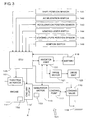
- a cargo handling apparatus A of a forklift 101 which is shown in Fig. 1 , is mainly composed of an engine 111, a generator-motor 113, a battery (electric storage means) 115, a loading pump 117, a loading valve 119, a fork 118, a drive motor 121, a drive unit 123, an inverter assembly 131, and an ECU (controller) 135.
- Cargo handling means is mainly composed of the loading pump 117, the fork 118, and the loading valve 119.
- the engine 111 is driven through a rotation control signal given to a throttle actuator 151 from the ECU 135 to be described later, and a drive shaft (not shown) thereof is coaxially coupled to a drive shaft (not shown) of the generator-motor 113 through a clutch 112 for disconnecting/connecting the power.
- the generator-motor 113 is driven by the engine 111 to generate power, and is appropriately switchable between a generator mode of storing the power in the battery 115 and a motor mode in which the generator-motor 113 is driven as a motor by receiving a supply of drive power from the battery 115.
- This control of switching is performed through the inverter assembly 131 on the basis of a control command of the ECU 135.
- sensors such as a shift position sensor 141, an acceleration switch 142, an acceleration position sensor 143, a loading lever switch 144, a loading lever position sensor (load detection means) 145, and an ignition switch 146. Those are electrically connected to the ECU 135.
- the engine 111 When the generator-motor 113 is in the generator mode, the engine 111 serves as a drive source of the generator-motor 113 and the loading pump 117, which are coaxially arranged. Meanwhile, when the generator-motor 113 is in the motor mode, the engine 111 and the generator-motor 113 serve as the drive sources of the loading pump 117. However, it is also possible to release the clutch 112 in the above-described motor mode, and to use only the generator-motor 113 instead of the engine 111 as the drive source of the loading pump 117. The control to release/connect the clutch is performed by a control signal of the ECU 135.
- the battery 115 stores the electric power generated by the generator-motor 113 in the generator mode, and appropriately supplies the drive power for a driving operation and a cargo handling operation of the forklift 101.
- the storage into the battery 115 and the discharge from the battery 115 are controlled through the inverter assembly 131 connected to the ECU 135.
- the driving operation of the forklift 101 is performed through the drive motor 121 and the drive unit 123 driven by the drive motor 121.
- the drive motor 121 is supplied with the drive power from the battery 115 through the inverter assembly 131 to be driven. Further, cargo handling work of the forklift 101 is performed through the loading pump 117, the fork 118, and the loading valve 119 for appropriately distributing an operation fluid from the loading pump 117 to the fork 118.
- the ECU 135 administers a system control of the entire forklift 101, and the control includes a storage/discharge control of the battery 115.
- the ECU 135 appropriately receives information such as shift position information from the shift position sensor 141, acceleration ON/OFF information from the acceleration switch 142, acceleration opening information from the acceleration position sensor 143, loading lever ON/OFF information from the loading lever switch 144, loading lever opening information from the loading lever position sensor 145, ON/OFF information from the ignition switch 146, information on the number of revolution (acquirable by a number of revolution detection sensor 152), temperature, and the like of the engine 111, voltage/temperature information from the battery 115, information on the number of revolution (acquirable by a number of revolution detection sensor 153), an output, temperature, and the like from the generator-motor 113.
- the control signal for the engine 111 is outputted to the throttle actuator 151, and various control signals such as a mode switching signal for the generator-motor 113, a storage control signal for the battery 115, and a control signal for the drive motor 121 are outputted to the inverter assembly 131, thereby executing the system control of the forklift 101.
- drive force of the engine 111 is transmitted through the clutch 112 in the connected state to the generator-motor 113 in the generator mode, and the electricity generated by the generator-motor 113 is sequentially stored in the battery 115.
- the loading pump 117 is constantly driven according to a rotational movement of the drive shaft of the engine 111, and sends the operation fluid (pressure oil in this embodiment) to the loading valve 119.
- the operation fluid passes through the loading valve 119, and is flown back to a tank (not shown).
- the ECU 135 makes a control to increase an amount of generated power for the battery 115, and makes a control so that a load applied to the engine 111 can be a suitable load for operating the engine 111 under a predetermined optimum condition.
- the optimum condition refers to a condition (number of revolution, amount of fuel injection, or the like) where the engine can be operated at the optimum fuel consumption, and is determined by performing experiments and the like. Note that when, for example, the cargo handling load is small and a charged amount of the battery 115 is nearly full, a control may be made by the ECU 135 so that the generator-motor 113 does not generate the power.
- the ECU 135 supplies the drive power from the battery 115 through the inverter assembly 113 to the drive motor 121.
- the drive motor 121 is driven so that the drive unit 123 coupled to the drive motor 121 performs the driving operation.
- the ECU 135 When the high output is required for the cargo handling work, that is, when the ECU 135 has determined that the request to drive for cargo handling is high on the basis of the information from the loading lever position sensor 145, the ECU 135 transmits the control signal to switch the generator-motor 113 to the motor mode. Note that in this case, the clutch 112 is set to the connected state in advance. Hereinafter, this state is referred to as a "second mode".
- the loading pump 117 is driven by both of the engine 111 and the generator-motor 113 in the motor mode.
- the generator-motor 113 in the motor mode assists the drive of the loading pump 117 by the engine 111, and even the engine 111 of a low-output type can sufficiently execute the cargo handling work requiring the high output.
- the ECU 135 When the ECU 135 has determined that the request to drive for cargo handling is relatively low, and that the output whose extent is such that the engine 111 and the generator-motor 113 in the motor mode must cooperate with each other is not required, the ECU 135 transmits the control signal to switch the generator-motor 113 into the motor mode, and sets the clutch 112 in a disconnection state. In this case, though the generator-motor 113 in the motor mode drives the loading pump 117, the engine 111 is not involved in the drive of the loading pump 117. Hereinafter, this state is referred to as a "third mode".
- the engine 111 is set to an idle state or a stopped state, thus making it possible to enhance energy efficiency when the loading pump 117 is driven. Further, the clutch 112 is set to the disconnection state. Accordingly, when the generator-motor 113 is driven, the large load (engine braking) is not applied thereto.
- the cargo handling load is increased because, for example, the opening of the loading lever position sensor 145 is increased.
- the ECU 135 investigates a degree (radicalness) of increase of this cargo handling load. For example, when the loading lever is inclined by a predetermined angle or more within a predetermined time, the ECU 135 determines that the degree (radicalness) of increase of the cargo handling load is large.
- the ECU 135 determines that the degree of increase of the cargo handling load falls below a predetermined value, the ECU 135 sends the control signal to the inverter assembly 131, and simply increases the output of the generator-motor 113 in the motor mode, thereby coping with the increase of the cargo handling load.
- the above-described clutch 112 remains in the disconnection state, and the engine 111 is set to the idle state or the stopped state, thus making it possible to enhance the energy efficiency.
- the ECU 135 makes a control to increase the output of the generator-motor 113 in the motor mode, and to immediately start the increase of the number of revolution of the engine 111.
- the ECU 135 immediately starts the engine 111 by a starter motor (not shown), and starts the increase of the number of revolution.
- the generator-motor 113 can be quickly shifted to a high-output state in comparison with the engine 111, and a delay of the cargo handling work can be minimized, or the delay can be reduced substantially to zero. Note that at the time of starting the increase of the number of revolution of the engine, the clutch 112 is left in the disconnection state.
- the ECU 135 monitors the number of revolution of the generator-motor 113 by the number of revolution detection sensor 153, and monitors the number of revolution of the engine 111 by the number of revolution detection sensor 152. Then, when the number of revolution of the engine 111 is made equal to the number of revolution of the generator-motor 113, the ECU 135 sets the clutch 112 in the connected state, and makes a control to drive the loading pump 117 by the large output of the engine 111. After the clutch 112 is set to the connected state, the drive of the generator-motor 113 in the motor mode may be stopped, or the drive may be continued to assist the output of the engine 111.
- the above-described third mode is employed, and the engine 111 is idled or stopped, thus enhancing the energy efficiency (fuel consumption).
- the drive is switched to the drive of the loading pump 117 by the engine 111 (or the drive of the loading pump 117 by the engine 111 and the generator-motor 113 in the motor mode), thus making it possible to perform the cargo handling work lightly by utilizing the large output by the engine 111.
- the period concerned can be dealt with by quickly increasing the output of the generator-motor 113. Accordingly, there is no fear for the delay of the cargo handling work owing to a lowering of operation responsiveness, and the efficiency of the cargo handling work is not lowered.
- control here is a control to set the clutch 112 in the connected state after the number of revolution of the engine 111 is made equal to the number of revolution of the generator-motor 113. Accordingly, the number of input revolutions of the loading pump 117 is also prevented from temporarily being lowered at the time the clutch 112 is set to the connected state. Hence, there is no case where the rising speed of the fork 118 temporarily falls during work of lifting up a cargo, resulting in generation of uncomfortable vibrations on a base or in a delay of the cargo handling work. Further, the control here is a control to set the clutch 112 in the connected state when both numbers of revolutions coincide with each other. Accordingly, seizing, wearing, and the like of the clutch 112 can also be avoided to thereby prolong a lifetime thereof.
- the ECU 135 can set the clutch 112 in the connected state and can drive the generator-motor 113 in the motor mode, thereby starting the engine 111.
- the dedicated starter motor can be omitted, thus making it possible to contribute to downsizing of the forklift 101 and reduce the number of parts and manufacturing cost.
- the generator-motor 113 in the motor mode is usually designed to have larger torque than the starter motor does. Accordingly, vibrations at the time of cranking can be reduced.
- a construction in which the engine 111 is started by cooperation of the starter motor and the generator-motor 113, can also be adopted.
- the dedicated starter motor a compact one (inexpensive one) having small torque can be employed, thus making it possible to achieve compactness of the forklift 101 and reduce the manufacturing cost.
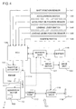
- Fig. 2 is a block diagram showing a construction of a forklift of a second embodiment.
- this second embodiment is different therefrom in that a CVT (continuously variable transmission) 114 is interposed between the generator-motor 113 and the engine 111. It is possible to control a transmission gear ratio of this CVT 114 by a control signal from the ECU 135.
- a CVT continuously variable transmission
- the clutch 112 is left in the disconnection state at an initial stage of the above-described increasing control of the number of revolution of the engine.
- the clutch 112 is set to the connected state to perform a control to shift the drive of the loading pump 117 to the drive by the engine 111.
- the ECU 135 sets the clutch 112 in the connected state when the number of revolution of the engine after gear shift is calculated on the basis of the above-described detection sensor 152 and a transmission ratio of the CVT 114 on the assumption that the clutch 112 has been set to the connected state and the power of the engine 111 has been shifted by the CVT 114 and when the obtained number of revolution is made equal to the number of revolution of the generator-motor 113.
- the clutch 112 is set to the connected state when the number of revolution of the engine whose speed has been increased by the CVT 114 is made equal to the number of revolution of the generator-motor 113. Accordingly, it is also possible to prevent the number of input revolutions of the loading pump 117 from temporarily being lowered at the time the clutch 112 is set to the connected state, and the seizing, wearing, and the like of the clutch 112 can also be avoided.
- the ECU 135 monitors the changes of the numbers of revolutions of the engine 111 and the generator-motor 113 by the number of revolution detection sensors 152 and 153. According to results of the monitoring, the ECU 135 changes the transmission ratio of the CVT 114. Specifically, the transmission ratio of the CVT 114 is controlled to be changed so as to maintain a synchronized state of the engine 111 and the generator-motor 113. In such a way, even during a period in which the number of revolution of the engine 111 is increased from the low state to be then equal to the number of revolution of the generator-motor 113, the drive force of the engine 111 can be transmitted to the loading pump 117.
- the engine 111 is set not in the idle state but in the stopped state in advance; when the radical increase of the cargo handling load has been detected, the output of the generator-motor 113 in the motor mode is increased; and substantially simultaneously therewith, the above-described clutch 112 is set to the connected state, thus allowing the generator-motor 113 to start the engine 111.
- the output of the generator-motor 113 by appropriately setting the transmission ratio of the CVT 114, the output of the generator-motor 113, with its speed being reduced and its torque being increased by the CVT 114, rotates the output shaft of the engine 111 to start the engine 111.
- the engine 111 can be started without applying any excessive load to the generator-motor 113. Further, in the above-described construction, it is needless to say that the dedicated starter motor can be omitted or downsized as in the above-described first embodiment, thus making it possible to contribute to the cost reduction and the like.
- a position of the CVT 114 is not limited to this construction, and a construction may also be adopted, for example, in which the CVT 114 is interposed between the clutch 112 and the engine 111.
- FIG. 3 A forklift of a third embodiment of the present invention is shown in Fig. 3 .
- This forklift 101 is constructed such that a one-way clutch 112' is provided between the generator-motor 113 and the engine 111 in place of the clutch 112 in the construction of Fig. 1 .
- a control is made to increase the output of the generator-motor 113 in the motor mode, and to immediately start the increase of the number of revolution of the engine 111. Note that when the engine 111 is stopped, the engine 111 is immediately started, and the increase of the number of revolution of the engine is started.
- the above-described one-way clutch 112' is automatically connected, and the drive force of the engine 111 is transmitted to the loading pump 117.
- the construction of Fig. 3 it is unnecessary to perform, on the ECU 135 side, the control as described above to connect the clutch after waiting for the following of the number of revolution of the engine. Therefore, the load on the ECU 135 can be reduced, and an electric construction thereof can be simplified. Further, it is unnecessary to make an electric control. Accordingly, a frequency of failure can be reduced, and the number of times of necessary maintenance can also be reduced.
- the CVT 114 as described in the second embodiment of the present invention may be used while being interposed between the one-way clutch 112' and the generator-motor 113, for instance.
- the engine 111 even if the engine 111 is to be started from the generator-motor 113 side, it is impossible to start the engine 111 since the one-way clutch 112' is set to the disconnection state.
- the engine 111 must be started by the dedicated starter motor.
Landscapes
- Engineering & Computer Science (AREA)
- Transportation (AREA)
- Mechanical Engineering (AREA)
- Combustion & Propulsion (AREA)
- Chemical & Material Sciences (AREA)
- Structural Engineering (AREA)
- Power Engineering (AREA)
- Life Sciences & Earth Sciences (AREA)
- Civil Engineering (AREA)
- Geology (AREA)
- Sustainable Development (AREA)
- Sustainable Energy (AREA)
- Forklifts And Lifting Vehicles (AREA)
- Hybrid Electric Vehicles (AREA)
- Control Of Vehicle Engines Or Engines For Specific Uses (AREA)
- Arrangement Or Mounting Of Propulsion Units For Vehicles (AREA)
- Control Of Transmission Device (AREA)
- Auxiliary Drives, Propulsion Controls, And Safety Devices (AREA)
Claims (11)
- Frachthandhabungsvorrichtung eines industriellen Frachthandhabungsfahrzeugs, mit
einer Maschine (111),
einem Motorgenerator (113),
einer Kupplung (112),
einer mit dem Motorgenerator (113) verbundenen elektrischen Speichereinrichtung (115), und
einer Steuereinrichtung (135),
wobei der Motorgenerator (113) betrieben ist in einer aus: einer Generatorbetriebsart, um durch ein betrieben sein durch mittels der Kupplung (112) übertragener Energie der Maschine (111) elektrische Energie zu erzeugen, und um die elektrische Energie in der elektrischen Speichereinrichtung (115) zu speichern, und einer Motorbetriebsart, um durch Empfang einer Zufuhr elektrischer Energie von der elektrischen Speichereinrichtung (115) als ein Motor betrieben zu sein,
dadurch gekennzeichnet, dass die Vorrichtung ferner aufweist
eine Frachthandhabungseinrichtung zur Durchführung einer Frachthandhabungsarbeit, und
eine Lasterfassungseinrichtung (145) zur Erfassung eines Ausmaßes einer Frachthandhabungslast,
wobei die Kupplung (112) dazu eingerichtet ist, um eine Übertragung von Energie zwischen der Maschine (111) und dem Motorgenerator (113) zu verbinden/trennen, und
wenn die durch die Lasterfassungseinrichtung (145) erfasste Last kleiner als ein vorbestimmter Wert ist, die Steuereinrichtung (135) die Maschine (111) in einen angehaltenen oder einen Leerlaufzustand versetzt, die Übertragung der Energie zwischen der Maschine (111) und dem Motorgenerator (113) mittels der Kupplung (112) trennt, und die Frachthandhabungseinrichtung durch den Motorgenerator (113) in der Motorbetriebsart antreibt, und dadurch die Frachthandhabungsarbeit durchführt, und
wenn die durch die Lasterfassungseinrichtung (145) erfasste Last während der Frachthandhabungsarbeit zu dem vorbestimmten Wert oder größer wird in einem Zustand, in dem die Übertragung der Energie zwischen der Maschine (111) und dem Motorgenerator (113) durch die Kupplung (112) getrennt ist, die Steuereinrichtung (135) eine Erhöhung der Umdrehungszahl der Maschine (111) während einer Erhöhung einer Ausgabe des Motorgenerators (113) in der Motorbetriebsart beginnt, und wenn die Umdrehungszahl der Maschine (111) an die Umdrehungszahl des Motorgenerators (113) angeglichen ist, die Steuereinrichtung (135) die Übertragung der Energie zwischen der Maschine (111) und dem Motorgenerator (113) durch die Kupplung (112) verbindet, und die Frachthandhabungseinrichtung mittels der Energie der Maschine (111) und der Energie des Motorgenerators (113) antreibt, und dadurch die Frachthandhabungsarbeit durchführt. - Frachthandhabungsvorrichtung eines industriellen Frachthandhabungsfahrzeugs nach Anspruch 1, ferner mit einem zwischen der Maschine (111) und dem Motorgenerator (113) angeordneten Stufenlosgetriebe (114).
- Frachthandhabungsvorrichtung eines industriellen Frachthandhabungsfahrzeugs nach Anspruch 2, wobei, wenn die Umdrehungszahl der Maschine (111), die durch das Stufenlosgetriebe (114) verlagert ist, an die Umdrehungszahl des Motorgenerators (113) angeglichen ist, nachdem die Erhöhung der Umdrehungszahl der Maschine (111) gestartet ist, die Übertragung der Energie zwischen der Maschine (111) und dem Motorgenerator (113) durch die Kupplung (112) verbunden ist.
- Frachthandhabungsvorrichtung eines industriellen Frachthandhabungsfahrzeugs nach Anspruch 3, wobei, nachdem die Umdrehungszahl der Maschine (111), die durch das Stufenlosgetriebe (114) verlagert ist, an die Umdrehungszahl des Motorgenerators (113) angeglichen ist, und die Übertragung der Energie zwischen der Maschine (111) und dem Motorgenerator (113) durch die Kupplung (112) verbunden ist, ein Übertragungsverhältnis des Stufenlosgetriebes (114) gesteuert ist, um gemäß der Erhöhung der Umdrehungszahl der Maschine (111) geändert zu werden.
- Frachthandhabungsvorrichtung eines industriellen Frachthandhabungsfahrzeugs nach Anspruch 4, wobei das Übertragungsverhältnis des Stufenlosgetriebes (114) gesteuert ist, um geändert zu werden, um einen synchronisierten Zustand der Maschine (111) und des Motorgenerators (113) beizubehalten gemäß der Erhöhung der Umdrehungszahl der Maschine (111).
- Frachthandhabungsvorrichtung eines industriellen Frachthandhabungsfahrzeugs nach Anspruch 1,
wobei die Steuereinrichtung (135) die Kupplung (112) in einen Trennzustand versetzt, wenn die durch die Lasterfassungseinrichtung (145) erfasste Last kleiner als der vorbestimmte Wert ist, und die Kupplung (112) in einen verbundenen Zustand versetzt, wenn die erhöhte Umdrehungszahl der Maschine (111) an die Umdrehungszahl des Motorgenerators (113) angeglichen ist in einem Fall, in dem die durch die Lasterfassungseinrichtung (145) erfasste Last während der Frachthandhabungsarbeit in dem Zustand, in dem die Übertragung der Energie zwischen der Maschine (111) und dem Motorgenerator (113) durch die Kupplung (112) getrennt ist, den vorbestimmten Wert oder größer annimmt. - Frachthandhabungsvorrichtung eines industriellen Frachthandhabungsfahrzeugs nach Anspruch 1, wobei
die Kupplung (112) aus einer Einwegkupplung (112') aufgebaut ist,
wenn die durch die Lasterfassungseinrichtung (145) erfasste Last kleiner als der vorbestimmte Wert ist, die Maschine (111) in einen angehaltenen oder einen Leerlaufzustand versetzt ist, um die Übertragung der Energie zwischen der Maschine (111) und dem Motorgenerator (113) automatisch zu trennen, und
in diesem Zustand, wenn die erhöhte Umdrehungszahl der Maschine (111) an die Umdrehungszahl des Motorgenerators (113) angeglichen ist in einem Fall, in dem die durch die Lasterfassungseinrichtung (145) erfasste Last den vorbestimmten Wert oder größer annimmt, die Übertragung der Energie zwischen der Maschine (111) und dem Motorgenerator (113) automatisch verbunden ist. - Frachthandhabungsvorrichtung eines industriellen Frachthandhabungsfahrzeugs nach Anspruch 1, wobei die Frachthandhabungseinrichtung eine Gabel (118) und eine zur Bewegung der Gabel (118) Drucköl ausspeisende Ladepumpe (117) aufweist.
- Frachthandhabungsvorrichtung eines industriellen Frachthandhabungsfahrzeugs nach Anspruch 1, wobei die Lasterfassungseinrichtung (145) einen eine Öffnung eines Ladehebels (144) erfassenden Ladehebelpositionssensor aufweist.
- Frachthandhabungsvorrichtung eines industriellen Frachthandhabungsfahrzeugs nach Anspruch 8, wobei die Lasterfassungseinrichtung (145) einen einen Druck des von der Ladepumpe (117) ausgespeisten Drucköls erfassenden Drucksensor (161) aufweist.
- Frachthandhabungsvorrichtung eines industriellen Frachthandhabungsfahrzeugs nach Anspruch 8, wobei die Lasterfassungseinrichtung (145) einen ein Gewicht einer durch die Gabel (118) angehobenen Fracht erfassenden Lastsensor (162) aufweist.
Applications Claiming Priority (2)
| Application Number | Priority Date | Filing Date | Title |
|---|---|---|---|
| JP2004118222A JP4399311B2 (ja) | 2004-04-13 | 2004-04-13 | 荷役作業用産業車両の荷役装置 |
| PCT/JP2005/005706 WO2005100230A1 (ja) | 2004-04-13 | 2005-03-28 | 荷役作業用産業車両の荷役装置 |
Publications (3)
| Publication Number | Publication Date |
|---|---|
| EP1736433A1 EP1736433A1 (de) | 2006-12-27 |
| EP1736433A4 EP1736433A4 (de) | 2008-04-23 |
| EP1736433B1 true EP1736433B1 (de) | 2014-01-15 |
Family
ID=35149899
Family Applications (1)
| Application Number | Title | Priority Date | Filing Date |
|---|---|---|---|
| EP05727165.2A Expired - Lifetime EP1736433B1 (de) | 2004-04-13 | 2005-03-28 | Frachthandhabungsvorrichtung für industrielles frachthandhabungsfahrzeug |
Country Status (9)
| Country | Link |
|---|---|
| US (1) | US7464778B2 (de) |
| EP (1) | EP1736433B1 (de) |
| JP (1) | JP4399311B2 (de) |
| KR (1) | KR100669876B1 (de) |
| CN (1) | CN100491230C (de) |
| AU (1) | AU2005232994B2 (de) |
| CA (1) | CA2530949C (de) |
| TW (1) | TWI290534B (de) |
| WO (1) | WO2005100230A1 (de) |
Families Citing this family (44)
| Publication number | Priority date | Publication date | Assignee | Title |
|---|---|---|---|---|
| US20070012493A1 (en) * | 2005-06-21 | 2007-01-18 | Jones Steven M | Dual hybrid propulsion system |
| JP5055972B2 (ja) * | 2006-01-12 | 2012-10-24 | 株式会社豊田自動織機 | 産業車両の荷役装置 |
| JP4052483B2 (ja) * | 2006-05-30 | 2008-02-27 | 三菱重工業株式会社 | 作業車両 |
| JP4957111B2 (ja) * | 2006-08-08 | 2012-06-20 | 株式会社豊田自動織機 | 産業車両の油圧装置 |
| CN101011942B (zh) * | 2007-02-12 | 2010-05-19 | 无锡开普动力有限公司 | 一种混合动力工业车辆 |
| GB2447229B (en) * | 2007-03-07 | 2011-11-02 | Niftylift Ltd | Mobile work platform with multiple mode drive system |
| DE102007014642A1 (de) | 2007-03-27 | 2008-10-02 | Still Gmbh | Flurförderzeug mit Hybridantrieb |
| JP5076612B2 (ja) * | 2007-04-20 | 2012-11-21 | 株式会社豊田自動織機 | 産業車両の荷役装置 |
| JP5193515B2 (ja) * | 2007-07-09 | 2013-05-08 | 株式会社豊田自動織機 | パラレルハイブリッドパワートレーン |
| JP5128871B2 (ja) * | 2007-08-08 | 2013-01-23 | 株式会社豊田自動織機 | ハイブリッド型荷役車両の荷役制御方法及び装置 |
| JP2009040211A (ja) * | 2007-08-08 | 2009-02-26 | Toyota Industries Corp | ハイブリッド型車両の回生電力制御方法及び装置 |
| KR101371968B1 (ko) | 2007-12-27 | 2014-03-25 | 주식회사 두산 | 전동지게차의 모터 제어방법 및 제어장치 |
| JP2009204127A (ja) * | 2008-02-28 | 2009-09-10 | Mitsubishi Heavy Ind Ltd | 車両制御ユニット及び該ユニットを搭載した車両 |
| CN101980881B (zh) * | 2008-03-27 | 2013-12-18 | 力至优三菱叉车株式会社 | 混合动力工业车辆 |
| JP5245524B2 (ja) * | 2008-05-08 | 2013-07-24 | 株式会社豊田自動織機 | ハイブリッド型荷役車両の荷役制御方法及び装置 |
| JP5309794B2 (ja) * | 2008-08-28 | 2013-10-09 | 株式会社豊田自動織機 | 荷役車両 |
| DE102008050553A1 (de) * | 2008-10-06 | 2010-04-15 | Wacker Neuson Se | Arbeitsgerät mit Hybridantrieb |
| US8205594B2 (en) * | 2008-10-29 | 2012-06-26 | Caterpillar Inc. | Genset control system having predictive load management |
| JP5035325B2 (ja) | 2009-11-12 | 2012-09-26 | 株式会社豊田自動織機 | 荷役車両の荷役制御装置 |
| JP4941539B2 (ja) | 2009-11-17 | 2012-05-30 | 株式会社豊田自動織機 | 荷役車両の駆動制御装置 |
| JP5045736B2 (ja) * | 2009-12-04 | 2012-10-10 | 株式会社豊田自動織機 | 産業車両の走行制御装置 |
| JP5556677B2 (ja) * | 2010-03-08 | 2014-07-23 | 株式会社豊田自動織機 | バッテリ充電回路 |
| BR112012022085B1 (pt) * | 2010-03-09 | 2020-12-08 | Nissan Motor Co., Ltd.P | transmissão automática e método de controle hidráulico destinado a mesma |
| JP5713785B2 (ja) * | 2011-04-25 | 2015-05-07 | シンフォニアテクノロジー株式会社 | 車載装置用動力システム |
| EP2749467B1 (de) | 2011-08-25 | 2018-01-10 | Toyota Jidosha Kabushiki Kaisha | Fahrzeug sowie fahrzeugsteuerungsverfahren und -vorrichtung |
| JP5702698B2 (ja) * | 2011-10-20 | 2015-04-15 | 本田技研工業株式会社 | 車両の駆動システム |
| AT512059B1 (de) * | 2011-10-27 | 2013-12-15 | Hitzinger Gmbh | Vorrichtung für einen unterbrechungsfreien mechanischen antrieb, insbesondere einer pumpe |
| JP5937349B2 (ja) * | 2011-12-20 | 2016-06-22 | 三井造船株式会社 | コンテナターミナルの非常用電力供給方法とコンテナターミナル |
| DE102011056751A1 (de) * | 2011-12-21 | 2013-06-27 | Still Gmbh | Mobile Arbeitsmaschine mit Startgenerator |
| JP2014009078A (ja) * | 2012-06-29 | 2014-01-20 | Tadano Ltd | 作業車両 |
| CN102897023B (zh) * | 2012-10-23 | 2015-02-18 | 安徽合力股份有限公司 | 具有发电机构的柔性连接液力变速箱 |
| TW201431771A (zh) * | 2013-02-07 | 2014-08-16 | bo-jun Chen | 堆高機負載對應式功率變化系統 |
| DE102013104439A1 (de) | 2013-04-30 | 2014-10-30 | Still Gmbh | Flurförderzeug mit verbrennungsmotorisch-elektrischem Antrieb |
| JP5838996B2 (ja) | 2013-05-13 | 2016-01-06 | 株式会社豊田自動織機 | 産業車両 |
| EP3013660A2 (de) | 2013-06-26 | 2016-05-04 | Parker Hannifin Manufacturing Limited | Energieeffizientes steuersystem für elektrofahrzeug |
| JP5867458B2 (ja) * | 2013-07-05 | 2016-02-24 | 株式会社豊田自動織機 | 産業車両 |
| US9701312B2 (en) * | 2013-12-11 | 2017-07-11 | Caterpillar Inc. | Idle reduction engine shutdown and restart system for a machine |
| KR102128385B1 (ko) * | 2013-12-24 | 2020-06-30 | 주식회사 두산 | 엔진식 지게차의 전원 이상 감지장치 및 감지방법 |
| US9745940B2 (en) | 2014-02-28 | 2017-08-29 | Caterpillar Inc. | Machine having hydraulic start assist system |
| CN104590019B (zh) * | 2014-12-19 | 2017-08-04 | 中国人民解放军军事交通学院 | 行车发电系统 |
| US10358123B2 (en) * | 2017-12-01 | 2019-07-23 | Gm Global Technology Operations Llc. | Multi-mode engine-disconnect clutch assemblies and control logic for hybrid electric vehicles |
| US10597022B2 (en) | 2018-02-01 | 2020-03-24 | GM Global Technology Operations LLC | Coordinated torque and speed control systems and logic for hybrid electric vehicles |
| CN116006460B (zh) * | 2022-12-30 | 2026-04-03 | 安百拓(南京)建筑矿山设备有限公司 | 一种地下铲运车的电液泵的控制方法、系统及地下铲运车 |
| CN117698682B (zh) * | 2023-12-04 | 2024-08-02 | 中联重科股份有限公司 | 混合动力作业机械设备的模式切换方法及模式切换系统 |
Family Cites Families (10)
| Publication number | Priority date | Publication date | Assignee | Title |
|---|---|---|---|---|
| JP2650600B2 (ja) * | 1993-04-27 | 1997-09-03 | 株式会社島津製作所 | フォークリフトの制御機構 |
| JP3167935B2 (ja) * | 1996-08-02 | 2001-05-21 | 本田技研工業株式会社 | ハイブリッド車両の制御装置 |
| CN2292785Y (zh) * | 1996-11-22 | 1998-09-30 | 马保柱 | 用于电动平衡重式叉车的双电机驱动装置 |
| JP3341659B2 (ja) * | 1997-12-05 | 2002-11-05 | 日産自動車株式会社 | ハイブリッド車の制御装置 |
| JP2000287305A (ja) | 1999-03-31 | 2000-10-13 | Unisia Jecs Corp | 発電電動ユニット |
| JP3692828B2 (ja) | 1999-04-28 | 2005-09-07 | 株式会社豊田自動織機 | 荷役作業用産業車両 |
| JP2001226096A (ja) * | 2000-02-15 | 2001-08-21 | Komatsu Forklift Co Ltd | 産業車両の転倒警報装置及び転倒防止装置 |
| US7077223B2 (en) | 2002-05-29 | 2006-07-18 | Honda Giken Kogyo Kabushiki Kaisha | Hybrid vehicle |
| JP2004001938A (ja) * | 2002-05-31 | 2004-01-08 | Nippon Yusoki Co Ltd | フォークリフト |
| JP2004073006A (ja) * | 2002-08-09 | 2004-03-11 | Iseki & Co Ltd | コンバイン等の源動力装置 |
-
2004
- 2004-04-13 JP JP2004118222A patent/JP4399311B2/ja not_active Expired - Fee Related
-
2005
- 2005-03-28 US US10/567,531 patent/US7464778B2/en not_active Expired - Fee Related
- 2005-03-28 KR KR1020067003211A patent/KR100669876B1/ko not_active Expired - Fee Related
- 2005-03-28 AU AU2005232994A patent/AU2005232994B2/en not_active Ceased
- 2005-03-28 CA CA002530949A patent/CA2530949C/en not_active Expired - Fee Related
- 2005-03-28 WO PCT/JP2005/005706 patent/WO2005100230A1/ja not_active Ceased
- 2005-03-28 CN CNB2005800007283A patent/CN100491230C/zh not_active Expired - Fee Related
- 2005-03-28 EP EP05727165.2A patent/EP1736433B1/de not_active Expired - Lifetime
- 2005-04-11 TW TW094111340A patent/TWI290534B/zh not_active IP Right Cessation
Also Published As
| Publication number | Publication date |
|---|---|
| EP1736433A4 (de) | 2008-04-23 |
| JP4399311B2 (ja) | 2010-01-13 |
| AU2005232994A1 (en) | 2005-10-27 |
| TW200604089A (en) | 2006-02-01 |
| US20080190703A1 (en) | 2008-08-14 |
| KR100669876B1 (ko) | 2007-01-16 |
| WO2005100230A1 (ja) | 2005-10-27 |
| CN100491230C (zh) | 2009-05-27 |
| AU2005232994B2 (en) | 2007-06-07 |
| KR20060033927A (ko) | 2006-04-20 |
| CA2530949A1 (en) | 2005-10-27 |
| CA2530949C (en) | 2008-04-29 |
| EP1736433A1 (de) | 2006-12-27 |
| TWI290534B (en) | 2007-12-01 |
| US7464778B2 (en) | 2008-12-16 |
| JP2005298163A (ja) | 2005-10-27 |
| CN1839091A (zh) | 2006-09-27 |
Similar Documents
| Publication | Publication Date | Title |
|---|---|---|
| US7464778B2 (en) | Cargo handling apparatus of cargo handling industrial vehicle | |
| RU2643080C2 (ru) | Способ управления натяжением приводного ремня двигателя, система натяжения приводного ремня двигателя и автомобиль, содержащий такую систему | |
| US10000205B2 (en) | Fail-safe control apparatus for hybrid vehicles | |
| US6712165B1 (en) | Hybrid vehicle | |
| US8983731B2 (en) | Method for controlling a power steering device for a motor vehicle equipped with a stop and start system | |
| JP2017177975A (ja) | ハイブリッド車両システム | |
| JP2008239041A (ja) | ハイブリッド車両 | |
| US7278503B1 (en) | Operating apparatus for a working industrial vehicle | |
| EP1937530B1 (de) | Verfahren und system zum abschalten eines motors in einem hybridfahrzeug | |
| WO2007012957A1 (en) | Method for reducing torque required to crank engine in hybrid vehicle | |
| CN102196936B (zh) | 离合器压缩机和转向助力泵装置以及用于控制该装置的方法 | |
| JP3946705B2 (ja) | パラレルハイブリッド車両 | |
| JP7846532B2 (ja) | 車両用制御装置 | |
| JP3704283B2 (ja) | エンジン自動停止始動装置 | |
| JP2007022406A (ja) | 無段変速機制御装置、車両制御装置及びその制御方法 | |
| JP6897509B2 (ja) | ハイブリッド車両のエンジン始動時制御装置 | |
| JP5825200B2 (ja) | 車両の制御装置 | |
| US12559086B2 (en) | Control device for hybrid vehicle | |
| US11702064B2 (en) | Hybrid vehicle | |
| KR101206690B1 (ko) | Isg 차량의 오일 펌프 구동 제어 장치 및 방법 | |
| US20240227770A9 (en) | In-vehicle controller | |
| JP6641215B2 (ja) | ハイブリッド車両システム、ハイブリッド車両システムの制御装置及びハイブリッド車両システムの制御方法 | |
| CN109328276B (zh) | 车辆的混合传动链的变速器的致动器的储压器的液压的控制设备 | |
| JP2017177969A (ja) | ハイブリッド車両システム、ハイブリッド車両システムの制御装置及びハイブリッド車両システムの制御方法 | |
| JP2023118396A (ja) | ハイブリッド車両の制御装置 |
Legal Events
| Date | Code | Title | Description |
|---|---|---|---|
| PUAI | Public reference made under article 153(3) epc to a published international application that has entered the european phase |
Free format text: ORIGINAL CODE: 0009012 |
|
| 17P | Request for examination filed |
Effective date: 20051223 |
|
| AK | Designated contracting states |
Kind code of ref document: A1 Designated state(s): DE FR GB IT SE |
|
| DAX | Request for extension of the european patent (deleted) | ||
| RBV | Designated contracting states (corrected) |
Designated state(s): DE FR GB IT SE |
|
| A4 | Supplementary search report drawn up and despatched |
Effective date: 20080326 |
|
| 17Q | First examination report despatched |
Effective date: 20110502 |
|
| GRAP | Despatch of communication of intention to grant a patent |
Free format text: ORIGINAL CODE: EPIDOSNIGR1 |
|
| INTG | Intention to grant announced |
Effective date: 20130729 |
|
| GRAS | Grant fee paid |
Free format text: ORIGINAL CODE: EPIDOSNIGR3 |
|
| GRAA | (expected) grant |
Free format text: ORIGINAL CODE: 0009210 |
|
| AK | Designated contracting states |
Kind code of ref document: B1 Designated state(s): DE FR GB IT SE |
|
| REG | Reference to a national code |
Ref country code: GB Ref legal event code: FG4D |
|
| RIC1 | Information provided on ipc code assigned before grant |
Ipc: B66F 9/24 20060101AFI20131209BHEP |
|
| REG | Reference to a national code |
Ref country code: DE Ref legal event code: R096 Ref document number: 602005042504 Country of ref document: DE Effective date: 20140227 |
|
| REG | Reference to a national code |
Ref country code: SE Ref legal event code: TRGR |
|
| REG | Reference to a national code |
Ref country code: DE Ref legal event code: R097 Ref document number: 602005042504 Country of ref document: DE |
|
| PLBE | No opposition filed within time limit |
Free format text: ORIGINAL CODE: 0009261 |
|
| STAA | Information on the status of an ep patent application or granted ep patent |
Free format text: STATUS: NO OPPOSITION FILED WITHIN TIME LIMIT |
|
| 26N | No opposition filed |
Effective date: 20141016 |
|
| REG | Reference to a national code |
Ref country code: DE Ref legal event code: R097 Ref document number: 602005042504 Country of ref document: DE Effective date: 20141016 |
|
| REG | Reference to a national code |
Ref country code: FR Ref legal event code: PLFP Year of fee payment: 11 |
|
| PGFP | Annual fee paid to national office [announced via postgrant information from national office to epo] |
Ref country code: DE Payment date: 20150324 Year of fee payment: 11 Ref country code: IT Payment date: 20150220 Year of fee payment: 11 |
|
| PGFP | Annual fee paid to national office [announced via postgrant information from national office to epo] |
Ref country code: SE Payment date: 20150311 Year of fee payment: 11 Ref country code: FR Payment date: 20150309 Year of fee payment: 11 Ref country code: GB Payment date: 20150325 Year of fee payment: 11 |
|
| REG | Reference to a national code |
Ref country code: DE Ref legal event code: R119 Ref document number: 602005042504 Country of ref document: DE |
|
| REG | Reference to a national code |
Ref country code: SE Ref legal event code: EUG |
|
| GBPC | Gb: european patent ceased through non-payment of renewal fee |
Effective date: 20160328 |
|
| PG25 | Lapsed in a contracting state [announced via postgrant information from national office to epo] |
Ref country code: SE Free format text: LAPSE BECAUSE OF NON-PAYMENT OF DUE FEES Effective date: 20160329 |
|
| REG | Reference to a national code |
Ref country code: FR Ref legal event code: ST Effective date: 20161130 |
|
| PG25 | Lapsed in a contracting state [announced via postgrant information from national office to epo] |
Ref country code: DE Free format text: LAPSE BECAUSE OF NON-PAYMENT OF DUE FEES Effective date: 20161001 Ref country code: GB Free format text: LAPSE BECAUSE OF NON-PAYMENT OF DUE FEES Effective date: 20160328 Ref country code: FR Free format text: LAPSE BECAUSE OF NON-PAYMENT OF DUE FEES Effective date: 20160331 |
|
| PG25 | Lapsed in a contracting state [announced via postgrant information from national office to epo] |
Ref country code: IT Free format text: LAPSE BECAUSE OF NON-PAYMENT OF DUE FEES Effective date: 20160328 |