EP1735224B1 - Vorrichtung zum transport von flachen gegenständen - Google Patents
Vorrichtung zum transport von flachen gegenständen Download PDFInfo
- Publication number
- EP1735224B1 EP1735224B1 EP05715968A EP05715968A EP1735224B1 EP 1735224 B1 EP1735224 B1 EP 1735224B1 EP 05715968 A EP05715968 A EP 05715968A EP 05715968 A EP05715968 A EP 05715968A EP 1735224 B1 EP1735224 B1 EP 1735224B1
- Authority
- EP
- European Patent Office
- Prior art keywords
- abutment
- conveying means
- flat articles
- driver element
- driver
- Prior art date
- Legal status (The legal status is an assumption and is not a legal conclusion. Google has not performed a legal analysis and makes no representation as to the accuracy of the status listed.)
- Expired - Lifetime
Links
Images
Classifications
-
- B—PERFORMING OPERATIONS; TRANSPORTING
- B65—CONVEYING; PACKING; STORING; HANDLING THIN OR FILAMENTARY MATERIAL
- B65G—TRANSPORT OR STORAGE DEVICES, e.g. CONVEYORS FOR LOADING OR TIPPING, SHOP CONVEYOR SYSTEMS OR PNEUMATIC TUBE CONVEYORS
- B65G17/00—Conveyors having an endless traction element, e.g. a chain, transmitting movement to a continuous or substantially-continuous load-carrying surface or to a series of individual load-carriers; Endless-chain conveyors in which the chains form the load-carrying surface
- B65G17/30—Details; Auxiliary devices
- B65G17/46—Means for holding or retaining the loads in fixed position on the load-carriers, e.g. magnetic
-
- B—PERFORMING OPERATIONS; TRANSPORTING
- B65—CONVEYING; PACKING; STORING; HANDLING THIN OR FILAMENTARY MATERIAL
- B65G—TRANSPORT OR STORAGE DEVICES, e.g. CONVEYORS FOR LOADING OR TIPPING, SHOP CONVEYOR SYSTEMS OR PNEUMATIC TUBE CONVEYORS
- B65G19/00—Conveyors comprising an impeller or a series of impellers carried by an endless traction element and arranged to move articles or materials over a supporting surface or underlying material, e.g. endless scraper conveyors
- B65G19/02—Conveyors comprising an impeller or a series of impellers carried by an endless traction element and arranged to move articles or materials over a supporting surface or underlying material, e.g. endless scraper conveyors for articles, e.g. for containers
Definitions
- the invention relates to a device for transporting flat objects according to the preamble of claim 1.
- Such devices are used, for example, in various processing machines, such as in machines for producing bags with molded bottoms of hose pieces, which are often formed of a tubular material.
- the sacks or pieces of hose are transported by the known transport devices to different processing stations in a transport direction, wherein a plurality of processing stations can be arranged along a single transport device.
- the flat objects are thereby taken or pulled along by a conveyor.
- known devices have a support associated with the counter-position. Between the conveyor and the counteracting acts a clamping force by which the flat objects are held in operative connection with the conveyor.
- the counter-position also consists of a subsidy.
- Both funds are in operative connection with the object, so that the object is relative to two funding at rest and is transported reliably.
- a discontinuous transport ie a clock transport
- the objects to be processed in the region of a processing station briefly relative to this must be at rest and only after processing on may be transported.
- the articles must also occupy a defined position relative to the processing station in its rest position.
- the flat objects may also occupy only certain positions relative to the conveyor within the device for transport.
- a disadvantage of the mentioned devices for the transport of flat objects is that the detection of the flat objects at the inlet end of the transport device takes place only at very inaccurately defined times. This is particularly the case when an article has to be transferred from a continuous transport to a discontinuous transport device. Thus, the positions of the flat objects relative to the conveyor are often subject to large errors and erroneous processing of the items the result.
- the publication DE 33 23 638 A1 shows, however, a device for transporting flat material parts, wherein the operative connection to the counter surface is realized with needles, which are inserted into a material to be transported material part. Even if such needles are replaced by blunt driving elements, which do not pierce the material, but only exert a clamping force, it could cause damage to the material.
- the object of the invention is therefore to propose a device for transporting flat objects, which avoids the said damages.
- the conveyor has at least two in the transport direction of the flat objects and in the transport direction offset from each other driver elements, which mediates at least a portion of said clamping force on the flat objects.
- This will be a flatter Object, which is located in the inlet region of the device, transported only when it comes into frictional engagement with a driver element.
- the inlet area and the transfer of the object is designed so that the driver element always detects an object at substantially the same areas.
- Each object to be transported thus assumes a fixed position relative to the conveying means.
- the holding means move as the objects in the transport direction, but need to be micht connected to the conveyor.
- the distance the individual driver elements depends on the cycle time in the batch transport and is at least the extent of the flat objects in the transport direction, for example at least 400mm.
- the counterweight can move at the same speed as the conveyor, but can move slower or be at rest. In both latter cases, the objects slide or slide along the counter-surface.
- the ratio of the static friction force of the driver element to the sliding friction force of the counter-surface must be greater than 1.
- the counter-layer may be coated with a rough material from a metal and the driver element at the surface, which is in contact with the object. However, other aids can also be used to influence the frictional forces.
- the counter-layer can be wetted with a lubricant.
- the driver element may have an electrostatic charge, so that the object, if it is electrically insulating material, is electrostatically attracted to the driver element.
- the counter-layer is usually made of a non-compliant material, so that the object is pressed by the driver element always with constant force and with the same position against the counter-surface.
- the at least one conveying means is at least one circulating, endless transport means such as a belt, a belt, a chain or a wheel.
- the advantage here is the use of a link chain. Such a link chain can be driven by gears.
- each driver element are displaceable in the direction of the counter-position in order to convey the clamping force.
- the components of the driving element need not be moved for the purpose of clamping. This measure prevents Excessive wear of the components of Mitauerlemias, the conveyor and / or the counter-surface.
- the at least one conveying means has at least two holding pieces, in which at least components of the driving elements are displaceably mounted. It is particularly easy to attach such holding pieces laterally to link chains.
- the holding pieces may be formed angularly and have holes, so that pin-like components of the driver element can be slidably mounted in these holes.
- each driver element has a compressible material on the side facing the counterpart, with which the operative connection of the flat objects to the at least one conveyor can be produced.
- a compressible material for example silicone rubber or rubber.
- Such materials increase the stiction between the driver element and the flat object.
- This compressible material can be applied separately to each driver element, however, a band-shaped material can also be used, which also spans the intermediate spaces between the driver elements and thus further increases the static friction.
- the compressible material may also be surrounded by spacers that extend beyond the compressible material such that in the absence of a flat object, the compressible material does not come into contact with the counter layer.
- two components attracting or repelling due to a magnetic interaction impart forces which make up at least part of the clamping forces imparting the driver elements to the flat objects.
- the first component in or on the counter-surface and the second component is arranged in or on the driver element.
- the first component is a spring steel sheet, which serves as an abutment or is part of the counter-surface.
- the spring steel sheet can be arranged so that the objects slide on it. In this way, a property of steel, namely a low coefficient of sliding friction, can be advantageously exploited.
- the second component is a magnet arranged on the driver element.
- This can be a permanent magnet or a switchable magnet in any way. In this way, the magnetic force acts only in the region of the driver element.
- the entrainment element comprises a spring which counteracts and is greater than the magnetic force when the distance between the two components, between which the magnetic interaction occurs, exceeds a minimum distance.
- This function of the spring is preceded by the consideration that the magnetic force between the driver element and counter-position increases with decreasing distance, with approximately a quadratic dependence being given.
- the spring force will be greater than the magnetic force of attraction.
- the driver element is pulled away from the counter-surface.
- the driver element is thus between an active position in which the flat object is guided by clamping, and a passive position back and forth switchable. This switching can be done by mechanical constraining forces, for example by cams, but also by increasing or decreasing the magnetic force.
- this switching is selectively carried out for each driver element. This avoids that the head of the driver element slipping in the absence of an object along the counter-position and thus leads to undesirable wear.
- a part of the counter-bearing is movable in the direction of and away from the conveying means. In the absence of the counter-acting on the driver element no magnetic force, so that this is returned to its initial gear position due to the spring force. Only in the presence of a flat object, the counter-position is moved in the direction of the conveyor. The presence of a flat object can be detected by a sensor which transmits a corresponding signal to a control device which causes the movement of the part of the counter-surface.
- Such a device according to the invention is preferably used in a device for the production of tissue sacks whose starting material is a round-woven, tubular material.
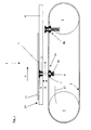
- Fig. 1 shows a schematic representation of a transport device 1.
- This includes a serving as a conveyor circumferential, endless link chain 2, which is driven or deflected by gears 3, which may be stored in the machine frame.
- At least two driver elements 4 are attached laterally to the link chain 2.
- a plurality of such driver elements 4 is provided in a transport device according to the invention.
- two driver elements wherein the driver element 4a in an extended, active and the driver element 4b is shown in a retracted, passive position.
- a table 6 is arranged, whose surface is the conveying plane for the transported flat objects 5, for example, tubular plastic materials.
- the flat objects 5 are thereby conveyed in the transport direction z.
- a driver element 4a, 4b consists of a holding piece 7, in which a bolt 8 is slidably mounted. The displacement is in a direction of the double arrow B. This direction is substantially orthogonal to the plane defined by the top of the table 6 conveying plane. Between the disc 9 and the retaining piece 7 a compression spring 10 surrounds the bolt 8, which acts in such a way that the driver element 4a, 4b without another force in its retracted , passive position remains, as illustrated by the driver element 4b.
- the driver element 4a is shown in its extended position. So that the driver element 4a remains in this position, its head 11 is equipped with a permanent magnet 12. Above a slit introduced into the table 6, through which the driver element 4a can pass, an abutment 13 made of spring band steel is fastened. If the permanent magnet 12 is close enough to the counter-position 13, the permanent magnet 12 interacts with the spring steel strip, so that the entire head 11 and the bolt 8 are moved against the force of the spring 10 in the direction of the counter-position 13, until the flat object 5 is clamped between the head 11 and the backsheet 13. In order to achieve such a close distance, is located below the inlet region 14 of the counter-guide 13, a guide 15 which raises the bolt 8 against the force of the compression spring 10.
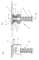
- FIG. 2 shows the structure of the driver element 4a, 4b in an enlarged view, showing the driver element 4b in its retracted position.
- the head 11 comprises a hinge connection 16 whose inner, convexly shaped ring 17 is secured to the upper end of the bolt 8.
- the outer ring 18 of the articulated connection 16 is inserted into a bore of the magnet carrier 19.
- In an upper recess of the magnetic carrier 19 of the annular or disc-shaped permanent magnet 12 is fixed in a manner not shown in detail.
- the hinge connection 16 it is ensured that the surface of the permanent magnet 12 facing the counter-surface 13 always runs plane-parallel to the counter-layer 13. This is important because the bolt 8 of the driver 4a, 4b is not orthogonal to the counter-13 due to the use of a flexible tension member in all operating situations, for example, an accelerated movement in clock mode with high clock frequency.
- the compressible coating 20 may consist of a silicone rubber or similar material.
- the upper edge 21 of the magnetic carrier 19 is occupied by needle-shaped, but blunt, spacers 22 which project slightly beyond the compressible coating 20.
- the Fig. 3 shows the view III - III according to Fig. 2 , from which it can be seen how the driver element 4 is preferably attached to a link chain 2.
- a Holding plate 23 is arranged laterally to the driver element 4a, b carrying holding piece 7 .
- a Holding plate 23 is arranged.
- these chain rivets 24 thus serve at the same time the connection of two link plates as well as the carrying of the driver element 4a, b.
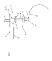
- the Fig. 4 shows the inlet-side section of a further embodiment of a device according to the invention there. Compared to the FIGS. 1 to 3 wurd the transport direction z of the flat objects not shown here reversed. All components not necessary for understanding the functioning of the inlet of the objects were described in the Fig. 4 not shown.
- the plate 25 is lowered.
- the plate 25 is connected via a piston 26 with any lifting mechanism.
- This can be a simple piston-cylinder unit, but also any other actuator. Only after the lowering process can form 12 forces between the plate 25 and the magnet, due to which the driver element 4 and the plate 25 can hold the flat object clamped. As long as the head 11 of the driver element 4 is not yet in the area of the counter-layer 13, the plate 25 remains lowered. Only then will she be driven back to her starting position.
- the plate 25 In the absence of a flat object, which can be detected by any sensor, the plate 25 remains in its initial position. Since now form only very weak magnetic forces between the magnet 12 and plate 25, the bolt 8 falls after sweeping over the end portion 27 of the guide 15 to its original position. The distance between magnet 12 and counter-surface 13 is now too large, so that the driver element 4 does not move in the direction of the counter-position.
- the Indian Fig. 4 The construction of the head 11 shown differs from that shown in the FIGS. 2 and 3 is shown.
- the magnet 12 is annular.
- a compressible element 28 is inserted, which has a cylindrical shape.
- a compressible element 28 for example, a rubber block can be used here.
Landscapes
- Engineering & Computer Science (AREA)
- Mechanical Engineering (AREA)
- Feeding Of Articles By Means Other Than Belts Or Rollers (AREA)
- Advancing Webs (AREA)
- Belt Conveyors (AREA)
- Auxiliary Devices For And Details Of Packaging Control (AREA)
Applications Claiming Priority (2)
| Application Number | Priority Date | Filing Date | Title |
|---|---|---|---|
| DE102004012755A DE102004012755B4 (de) | 2004-03-15 | 2004-03-15 | Vorrichtung zum Transport von flachen Gegenständen |
| PCT/EP2005/002602 WO2005092747A1 (de) | 2004-03-15 | 2005-03-10 | Vorrichtung zum transport von flachen gegenständen |
Publications (2)
| Publication Number | Publication Date |
|---|---|
| EP1735224A1 EP1735224A1 (de) | 2006-12-27 |
| EP1735224B1 true EP1735224B1 (de) | 2011-01-05 |
Family
ID=34962102
Family Applications (1)
| Application Number | Title | Priority Date | Filing Date |
|---|---|---|---|
| EP05715968A Expired - Lifetime EP1735224B1 (de) | 2004-03-15 | 2005-03-10 | Vorrichtung zum transport von flachen gegenständen |
Country Status (8)
| Country | Link |
|---|---|
| EP (1) | EP1735224B1 (enExample) |
| JP (1) | JP5060283B2 (enExample) |
| CN (1) | CN1930061B (enExample) |
| AT (1) | ATE494245T1 (enExample) |
| BR (1) | BRPI0508705A (enExample) |
| DE (2) | DE102004012755B4 (enExample) |
| ES (1) | ES2357583T3 (enExample) |
| WO (1) | WO2005092747A1 (enExample) |
Families Citing this family (7)
| Publication number | Priority date | Publication date | Assignee | Title |
|---|---|---|---|---|
| DE102010000775B4 (de) * | 2010-01-11 | 2016-08-04 | Norditec Antriebstechnik Gmbh | Verfahren zum Verpacken einer Verpackungscharge und Vorrichtung zur Durchführung des Verfahrens |
| DE202011110277U1 (de) * | 2011-06-14 | 2013-04-08 | Hans Hundegger | Riemen- oder Kettentrieb |
| JP5875116B2 (ja) * | 2012-06-04 | 2016-03-02 | 株式会社椿本チエイン | チェーン搬送装置 |
| CN104444094A (zh) * | 2014-11-25 | 2015-03-25 | 南通贝特医药机械有限公司 | 柱式料斗混合机的提升机夹紧装置 |
| CN108516388B (zh) * | 2018-04-16 | 2020-06-19 | 盐城易动科技服务有限公司 | 一种布料传输机构 |
| CN109573467B (zh) * | 2019-01-04 | 2020-06-05 | 石思思 | 一种木材加工用原木输送机构 |
| CN110697332B (zh) * | 2019-10-18 | 2021-05-04 | 新昌县益旭龙机械科技有限公司 | 一种安检传送带 |
Family Cites Families (21)
| Publication number | Priority date | Publication date | Assignee | Title |
|---|---|---|---|---|
| DE1956580U (de) * | 1966-12-21 | 1967-03-02 | Pfaff Ag G M | Vorrichtung zum ueberfuehren von werkstuecken. |
| US3908816A (en) * | 1971-04-22 | 1975-09-30 | Coats Ltd J & P | Conveyor device |
| GB1393268A (en) * | 1972-12-19 | 1975-05-07 | Philips Electronic Associated | Magnetic conveyor |
| DE2362626A1 (de) * | 1973-12-17 | 1975-06-19 | Geb Weingaertner Gisela Berger | Rollo-schutzeinrichtung fuer frei abgestellte automobile |
| CH592562A5 (enExample) * | 1974-05-28 | 1977-10-31 | Ferag Ag | |
| DE3001742A1 (de) * | 1980-01-18 | 1981-07-23 | Adolf Illig Maschinenbau Gmbh & Co, 7100 Heilbronn | Halteklammer zum festklemmen einer materialbahn |
| JPS5842094B2 (ja) * | 1980-07-03 | 1983-09-17 | オリエンタルチエン工業株式会社 | クリツプチエン |
| JPS58216804A (ja) * | 1982-06-11 | 1983-12-16 | Furukawa Electric Co Ltd:The | 磁性ベルトコンベア装置 |
| DE3316518C2 (de) * | 1983-05-06 | 1985-10-03 | IMA - Klessmann GmbH & Co KG, 4830 Gütersloh | Transportvorrichtung für plattenförmige Werkstücke, wie Möbelteile |
| DE3323638A1 (de) * | 1983-06-30 | 1985-01-03 | Blomberger Holzindustrie B. Hausmann GmbH & Co KG, 4933 Blomberg | Transport-verfahren sowie vorrichtung zu seiner durchfuehrung |
| DE3632187A1 (de) * | 1986-09-23 | 1988-03-31 | Nordischer Maschinenbau | Bearbeitungsanlage fuer gefluegelkoerper |
| US4801003A (en) * | 1986-11-05 | 1989-01-31 | Alessandro Costa | Conveyor and devices for conveying movable planes on automatic distribution lines showing a plan preferably quadrangular |
| IT1228029B (it) * | 1988-12-15 | 1991-05-27 | Salvagnini Transferica S P A S | Manipolatore di fogli piani, in particolare di lamiera |
| DE4210188C2 (de) * | 1992-03-30 | 1995-05-18 | Christian Dipl Ing Boehner | Transportanlage zur Förderung von Gütern entlang einer vorgegebenen Förderlinie |
| JP2824373B2 (ja) * | 1992-12-15 | 1998-11-11 | 株式会社ミューチュアル | 搬送機における物品の吸着装置 |
| DE19629051A1 (de) * | 1996-07-18 | 1998-01-22 | Gaemmerler Hagen | Fördersystem mit Greifklammern |
| DE19847249C2 (de) * | 1998-10-14 | 2003-12-24 | Ima Maschinenfabriken Klessmann Gmbh | Umlaufende Transportkette für eine Durchlaufmaschine |
| DE19938879A1 (de) * | 1999-08-17 | 2001-03-08 | Bartec Componenten & Syst Gmbh | Flaschenbeförderungssystem und Verfahren zum Befördern von Flaschen |
| DE10005019A1 (de) * | 2000-02-04 | 2001-08-09 | Rovema Gmbh | Vorrichtung zum Weiterbewegen von Gegenständen |
| DE10011680C2 (de) * | 2000-03-10 | 2003-10-30 | Boewe Systec Ag | Vorrichtung zum Transport von flächigem Gut |
| CN2432191Y (zh) * | 2000-06-20 | 2001-05-30 | 董君良 | 链条式输送夹带 |
-
2004
- 2004-03-15 DE DE102004012755A patent/DE102004012755B4/de not_active Expired - Fee Related
-
2005
- 2005-03-10 WO PCT/EP2005/002602 patent/WO2005092747A1/de not_active Ceased
- 2005-03-10 ES ES05715968T patent/ES2357583T3/es not_active Expired - Lifetime
- 2005-03-10 BR BRPI0508705-8A patent/BRPI0508705A/pt active Search and Examination
- 2005-03-10 CN CN200580008216.1A patent/CN1930061B/zh not_active Expired - Fee Related
- 2005-03-10 EP EP05715968A patent/EP1735224B1/de not_active Expired - Lifetime
- 2005-03-10 JP JP2007503249A patent/JP5060283B2/ja not_active Expired - Fee Related
- 2005-03-10 DE DE502005010800T patent/DE502005010800D1/de not_active Expired - Lifetime
- 2005-03-10 AT AT05715968T patent/ATE494245T1/de active
Also Published As
| Publication number | Publication date |
|---|---|
| DE102004012755B4 (de) | 2007-10-04 |
| DE502005010800D1 (de) | 2011-02-17 |
| BRPI0508705A (pt) | 2007-08-07 |
| ATE494245T1 (de) | 2011-01-15 |
| CN1930061B (zh) | 2013-06-19 |
| ES2357583T3 (es) | 2011-04-27 |
| WO2005092747A1 (de) | 2005-10-06 |
| JP2007529386A (ja) | 2007-10-25 |
| JP5060283B2 (ja) | 2012-10-31 |
| CN1930061A (zh) | 2007-03-14 |
| EP1735224A1 (de) | 2006-12-27 |
| DE102004012755A1 (de) | 2005-10-13 |
Similar Documents
| Publication | Publication Date | Title |
|---|---|---|
| EP2265523B1 (de) | Vorrichtung zum fördern von produkten | |
| WO2017162859A1 (de) | Anschlagmodul zum positionsgenauen anhalten eines gegenstands | |
| EP1735224B1 (de) | Vorrichtung zum transport von flachen gegenständen | |
| EP1567431B1 (de) | Fördersystem für flache nicht-magnetische gegenstände | |
| DE69509524T2 (de) | Vorrichtung zum einzelfördern von werkstücken und vorratsbehälter für werkstücke | |
| EP3031759B1 (de) | Vorrichtung und dazugehöriges verfahren zum fördern und transferieren von flexiblen flächigen gegenständen | |
| DE102004051323A1 (de) | Maschine zur Verarbeitung von Bedruckstoffbogen | |
| DE102010005337A1 (de) | Vorrichtung zum Befestigen eines Gegenstandes an einer Tragstruktur und Skid mit einer solchen Vorrichtung | |
| DE102011052445A1 (de) | Sortierer | |
| DE69313490T2 (de) | Greiferförderer | |
| WO2003066490A2 (de) | Transportsystem | |
| DE19939526B4 (de) | Greifer zum Ergreifen flacher Produkte | |
| EP1541277B1 (de) | Positioniereinheit und Transportsystem mit Positioniereinrichtung | |
| EP1318088B1 (de) | Spannvorrichtung und Umsetzvorrichtung mit einer derartigen Spannvorrichtung | |
| DE102011108063A1 (de) | Vorrichtung und Verfahren zum Stoppen und/oder Ausrichten von Transportgütern auf einer Fördereinrichtung und Fördereinrichtung | |
| DE202021004502U1 (de) | Fördervorrichtung mit einem endlos umlaufenden Förderriemen zum Fördern einer Transporteinrichtung, mittels der ein Fördergut transportierbar ist | |
| EP3321217B1 (de) | Fördersystem zum fördern mindestens eines werkstücks | |
| DE102016206223A1 (de) | Plattenwechsler | |
| EP1167545B1 (de) | Bandmesserspaltmaschine | |
| DE4335740A1 (de) | Vorrichtung zur Vereinzelung von Gegenständen | |
| EP2036840B1 (de) | Vorrichtung zur Aufnahme und zum Transport eines Gutes | |
| EP3515847A1 (de) | Vorrichtung zum zuführen einer mehrzahl flächig aneinander anliegender, flächiger elementen, insbesondere kartonzuschnitten, zu einer verpackungsvorrichtung | |
| WO2002020269A1 (de) | Ein verfahren und vorrichtungen zum einziehen und übergeben eines anfanges einer bahn | |
| DE4216372A1 (de) | Fördervorrichtung für empfindliche Stückgüter, insbesondere keramische Formlinge | |
| DE102024136432A1 (de) | Förderanordnung mit Übergabeförderer |
Legal Events
| Date | Code | Title | Description |
|---|---|---|---|
| PUAI | Public reference made under article 153(3) epc to a published international application that has entered the european phase |
Free format text: ORIGINAL CODE: 0009012 |
|
| 17P | Request for examination filed |
Effective date: 20061016 |
|
| AK | Designated contracting states |
Kind code of ref document: A1 Designated state(s): AT BE BG CH CY CZ DE DK EE ES FI FR GB GR HU IE IS IT LI LT LU MC NL PL PT RO SE SI SK TR |
|
| 17Q | First examination report despatched |
Effective date: 20070410 |
|
| DAX | Request for extension of the european patent (deleted) | ||
| GRAP | Despatch of communication of intention to grant a patent |
Free format text: ORIGINAL CODE: EPIDOSNIGR1 |
|
| GRAS | Grant fee paid |
Free format text: ORIGINAL CODE: EPIDOSNIGR3 |
|
| GRAA | (expected) grant |
Free format text: ORIGINAL CODE: 0009210 |
|
| AK | Designated contracting states |
Kind code of ref document: B1 Designated state(s): AT BE BG CH CY CZ DE DK EE ES FI FR GB GR HU IE IS IT LI LT LU MC NL PL PT RO SE SI SK TR |
|
| REG | Reference to a national code |
Ref country code: GB Ref legal event code: FG4D Free format text: NOT ENGLISH |
|
| REG | Reference to a national code |
Ref country code: CH Ref legal event code: EP |
|
| REG | Reference to a national code |
Ref country code: IE Ref legal event code: FG4D Free format text: LANGUAGE OF EP DOCUMENT: GERMAN |
|
| REF | Corresponds to: |
Ref document number: 502005010800 Country of ref document: DE Date of ref document: 20110217 Kind code of ref document: P |
|
| REG | Reference to a national code |
Ref country code: DE Ref legal event code: R096 Ref document number: 502005010800 Country of ref document: DE Effective date: 20110217 |
|
| REG | Reference to a national code |
Ref country code: ES Ref legal event code: FG2A Ref document number: 2357583 Country of ref document: ES Kind code of ref document: T3 Effective date: 20110427 |
|
| REG | Reference to a national code |
Ref country code: NL Ref legal event code: VDEP Effective date: 20110105 |
|
| PG25 | Lapsed in a contracting state [announced via postgrant information from national office to epo] |
Ref country code: SI Free format text: LAPSE BECAUSE OF FAILURE TO SUBMIT A TRANSLATION OF THE DESCRIPTION OR TO PAY THE FEE WITHIN THE PRESCRIBED TIME-LIMIT Effective date: 20110105 |
|
| LTIE | Lt: invalidation of european patent or patent extension |
Effective date: 20110105 |
|
| PG25 | Lapsed in a contracting state [announced via postgrant information from national office to epo] |
Ref country code: GR Free format text: LAPSE BECAUSE OF FAILURE TO SUBMIT A TRANSLATION OF THE DESCRIPTION OR TO PAY THE FEE WITHIN THE PRESCRIBED TIME-LIMIT Effective date: 20110406 Ref country code: LT Free format text: LAPSE BECAUSE OF FAILURE TO SUBMIT A TRANSLATION OF THE DESCRIPTION OR TO PAY THE FEE WITHIN THE PRESCRIBED TIME-LIMIT Effective date: 20110105 Ref country code: IS Free format text: LAPSE BECAUSE OF FAILURE TO SUBMIT A TRANSLATION OF THE DESCRIPTION OR TO PAY THE FEE WITHIN THE PRESCRIBED TIME-LIMIT Effective date: 20110505 Ref country code: SE Free format text: LAPSE BECAUSE OF FAILURE TO SUBMIT A TRANSLATION OF THE DESCRIPTION OR TO PAY THE FEE WITHIN THE PRESCRIBED TIME-LIMIT Effective date: 20110105 Ref country code: PT Free format text: LAPSE BECAUSE OF FAILURE TO SUBMIT A TRANSLATION OF THE DESCRIPTION OR TO PAY THE FEE WITHIN THE PRESCRIBED TIME-LIMIT Effective date: 20110505 |
|
| REG | Reference to a national code |
Ref country code: IE Ref legal event code: FD4D |
|
| PG25 | Lapsed in a contracting state [announced via postgrant information from national office to epo] |
Ref country code: CY Free format text: LAPSE BECAUSE OF FAILURE TO SUBMIT A TRANSLATION OF THE DESCRIPTION OR TO PAY THE FEE WITHIN THE PRESCRIBED TIME-LIMIT Effective date: 20110105 Ref country code: PL Free format text: LAPSE BECAUSE OF FAILURE TO SUBMIT A TRANSLATION OF THE DESCRIPTION OR TO PAY THE FEE WITHIN THE PRESCRIBED TIME-LIMIT Effective date: 20110105 Ref country code: FI Free format text: LAPSE BECAUSE OF FAILURE TO SUBMIT A TRANSLATION OF THE DESCRIPTION OR TO PAY THE FEE WITHIN THE PRESCRIBED TIME-LIMIT Effective date: 20110105 Ref country code: BG Free format text: LAPSE BECAUSE OF FAILURE TO SUBMIT A TRANSLATION OF THE DESCRIPTION OR TO PAY THE FEE WITHIN THE PRESCRIBED TIME-LIMIT Effective date: 20110405 Ref country code: NL Free format text: LAPSE BECAUSE OF FAILURE TO SUBMIT A TRANSLATION OF THE DESCRIPTION OR TO PAY THE FEE WITHIN THE PRESCRIBED TIME-LIMIT Effective date: 20110105 |
|
| REG | Reference to a national code |
Ref country code: HU Ref legal event code: AG4A Ref document number: E010884 Country of ref document: HU |
|
| BERE | Be: lapsed |
Owner name: WINDMOLLER & HOLSCHER K.G. Effective date: 20110331 |
|
| PG25 | Lapsed in a contracting state [announced via postgrant information from national office to epo] |
Ref country code: MC Free format text: LAPSE BECAUSE OF NON-PAYMENT OF DUE FEES Effective date: 20110331 Ref country code: DK Free format text: LAPSE BECAUSE OF FAILURE TO SUBMIT A TRANSLATION OF THE DESCRIPTION OR TO PAY THE FEE WITHIN THE PRESCRIBED TIME-LIMIT Effective date: 20110105 Ref country code: EE Free format text: LAPSE BECAUSE OF FAILURE TO SUBMIT A TRANSLATION OF THE DESCRIPTION OR TO PAY THE FEE WITHIN THE PRESCRIBED TIME-LIMIT Effective date: 20110105 Ref country code: IE Free format text: LAPSE BECAUSE OF FAILURE TO SUBMIT A TRANSLATION OF THE DESCRIPTION OR TO PAY THE FEE WITHIN THE PRESCRIBED TIME-LIMIT Effective date: 20110105 |
|
| REG | Reference to a national code |
Ref country code: CH Ref legal event code: PL |
|
| PLBE | No opposition filed within time limit |
Free format text: ORIGINAL CODE: 0009261 |
|
| STAA | Information on the status of an ep patent application or granted ep patent |
Free format text: STATUS: NO OPPOSITION FILED WITHIN TIME LIMIT |
|
| PG25 | Lapsed in a contracting state [announced via postgrant information from national office to epo] |
Ref country code: CZ Free format text: LAPSE BECAUSE OF FAILURE TO SUBMIT A TRANSLATION OF THE DESCRIPTION OR TO PAY THE FEE WITHIN THE PRESCRIBED TIME-LIMIT Effective date: 20110105 Ref country code: SK Free format text: LAPSE BECAUSE OF FAILURE TO SUBMIT A TRANSLATION OF THE DESCRIPTION OR TO PAY THE FEE WITHIN THE PRESCRIBED TIME-LIMIT Effective date: 20110105 Ref country code: RO Free format text: LAPSE BECAUSE OF FAILURE TO SUBMIT A TRANSLATION OF THE DESCRIPTION OR TO PAY THE FEE WITHIN THE PRESCRIBED TIME-LIMIT Effective date: 20110105 |
|
| 26N | No opposition filed |
Effective date: 20111006 |
|
| REG | Reference to a national code |
Ref country code: FR Ref legal event code: ST Effective date: 20111130 |
|
| GBPC | Gb: european patent ceased through non-payment of renewal fee |
Effective date: 20110405 |
|
| PG25 | Lapsed in a contracting state [announced via postgrant information from national office to epo] |
Ref country code: BE Free format text: LAPSE BECAUSE OF NON-PAYMENT OF DUE FEES Effective date: 20110331 Ref country code: IT Free format text: LAPSE BECAUSE OF FAILURE TO SUBMIT A TRANSLATION OF THE DESCRIPTION OR TO PAY THE FEE WITHIN THE PRESCRIBED TIME-LIMIT Effective date: 20110105 |
|
| PG25 | Lapsed in a contracting state [announced via postgrant information from national office to epo] |
Ref country code: CH Free format text: LAPSE BECAUSE OF NON-PAYMENT OF DUE FEES Effective date: 20110331 Ref country code: LI Free format text: LAPSE BECAUSE OF NON-PAYMENT OF DUE FEES Effective date: 20110331 Ref country code: FR Free format text: LAPSE BECAUSE OF NON-PAYMENT OF DUE FEES Effective date: 20110331 |
|
| REG | Reference to a national code |
Ref country code: DE Ref legal event code: R097 Ref document number: 502005010800 Country of ref document: DE Effective date: 20111006 |
|
| PG25 | Lapsed in a contracting state [announced via postgrant information from national office to epo] |
Ref country code: GB Free format text: LAPSE BECAUSE OF NON-PAYMENT OF DUE FEES Effective date: 20110405 |
|
| PG25 | Lapsed in a contracting state [announced via postgrant information from national office to epo] |
Ref country code: LU Free format text: LAPSE BECAUSE OF NON-PAYMENT OF DUE FEES Effective date: 20110310 |
|
| PG25 | Lapsed in a contracting state [announced via postgrant information from national office to epo] |
Ref country code: TR Free format text: LAPSE BECAUSE OF FAILURE TO SUBMIT A TRANSLATION OF THE DESCRIPTION OR TO PAY THE FEE WITHIN THE PRESCRIBED TIME-LIMIT Effective date: 20110105 |
|
| PGFP | Annual fee paid to national office [announced via postgrant information from national office to epo] |
Ref country code: AT Payment date: 20170328 Year of fee payment: 13 Ref country code: HU Payment date: 20170330 Year of fee payment: 13 |
|
| PGFP | Annual fee paid to national office [announced via postgrant information from national office to epo] |
Ref country code: DE Payment date: 20170331 Year of fee payment: 13 |
|
| PGFP | Annual fee paid to national office [announced via postgrant information from national office to epo] |
Ref country code: ES Payment date: 20170425 Year of fee payment: 13 |
|
| REG | Reference to a national code |
Ref country code: DE Ref legal event code: R119 Ref document number: 502005010800 Country of ref document: DE |
|
| REG | Reference to a national code |
Ref country code: AT Ref legal event code: MM01 Ref document number: 494245 Country of ref document: AT Kind code of ref document: T Effective date: 20180310 |
|
| PG25 | Lapsed in a contracting state [announced via postgrant information from national office to epo] |
Ref country code: HU Free format text: LAPSE BECAUSE OF NON-PAYMENT OF DUE FEES Effective date: 20180311 Ref country code: DE Free format text: LAPSE BECAUSE OF NON-PAYMENT OF DUE FEES Effective date: 20181002 Ref country code: AT Free format text: LAPSE BECAUSE OF NON-PAYMENT OF DUE FEES Effective date: 20180310 |
|
| REG | Reference to a national code |
Ref country code: ES Ref legal event code: FD2A Effective date: 20190904 |
|
| PG25 | Lapsed in a contracting state [announced via postgrant information from national office to epo] |
Ref country code: ES Free format text: LAPSE BECAUSE OF NON-PAYMENT OF DUE FEES Effective date: 20180311 |