EP1731799B1 - Rack and pinion-type steering device - Google Patents
Rack and pinion-type steering device Download PDFInfo
- Publication number
- EP1731799B1 EP1731799B1 EP05703490A EP05703490A EP1731799B1 EP 1731799 B1 EP1731799 B1 EP 1731799B1 EP 05703490 A EP05703490 A EP 05703490A EP 05703490 A EP05703490 A EP 05703490A EP 1731799 B1 EP1731799 B1 EP 1731799B1
- Authority
- EP
- European Patent Office
- Prior art keywords
- pinion
- teeth
- rack
- tooth
- shaft
- Prior art date
- Legal status (The legal status is an assumption and is not a legal conclusion. Google has not performed a legal analysis and makes no representation as to the accuracy of the status listed.)
- Ceased
Links
- 238000012986 modification Methods 0.000 claims description 21
- 230000004048 modification Effects 0.000 claims description 21
- 238000005299 abrasion Methods 0.000 description 9
- 230000015556 catabolic process Effects 0.000 description 9
- 238000005452 bending Methods 0.000 description 6
- 238000006731 degradation reaction Methods 0.000 description 6
- 230000000694 effects Effects 0.000 description 5
- 238000006243 chemical reaction Methods 0.000 description 4
- 238000000034 method Methods 0.000 description 4
- 230000009467 reduction Effects 0.000 description 4
- 238000013461 design Methods 0.000 description 3
- 238000009826 distribution Methods 0.000 description 3
- 238000002474 experimental method Methods 0.000 description 3
- 238000010438 heat treatment Methods 0.000 description 3
- 230000005540 biological transmission Effects 0.000 description 2
- 238000005520 cutting process Methods 0.000 description 2
- 238000010586 diagram Methods 0.000 description 2
- 230000008569 process Effects 0.000 description 2
- 238000012545 processing Methods 0.000 description 2
- 230000004044 response Effects 0.000 description 2
- 238000010187 selection method Methods 0.000 description 2
- 238000012360 testing method Methods 0.000 description 2
- 229920000535 Tan II Polymers 0.000 description 1
- 230000001154 acute effect Effects 0.000 description 1
- 238000005255 carburizing Methods 0.000 description 1
- 230000000295 complement effect Effects 0.000 description 1
- 238000012937 correction Methods 0.000 description 1
- 230000000593 degrading effect Effects 0.000 description 1
- 238000006073 displacement reaction Methods 0.000 description 1
- 230000006872 improvement Effects 0.000 description 1
- 238000005259 measurement Methods 0.000 description 1
- 238000013021 overheating Methods 0.000 description 1
- 230000002093 peripheral effect Effects 0.000 description 1
- 230000002028 premature Effects 0.000 description 1
- 238000010791 quenching Methods 0.000 description 1
- 230000000171 quenching effect Effects 0.000 description 1
Images

Classifications
-
- F—MECHANICAL ENGINEERING; LIGHTING; HEATING; WEAPONS; BLASTING
- F16—ENGINEERING ELEMENTS AND UNITS; GENERAL MEASURES FOR PRODUCING AND MAINTAINING EFFECTIVE FUNCTIONING OF MACHINES OR INSTALLATIONS; THERMAL INSULATION IN GENERAL
- F16H—GEARING
- F16H55/00—Elements with teeth or friction surfaces for conveying motion; Worms, pulleys or sheaves for gearing mechanisms
- F16H55/02—Toothed members; Worms
- F16H55/08—Profiling
- F16H55/0806—Involute profile
-
- B—PERFORMING OPERATIONS; TRANSPORTING
- B62—LAND VEHICLES FOR TRAVELLING OTHERWISE THAN ON RAILS
- B62D—MOTOR VEHICLES; TRAILERS
- B62D3/00—Steering gears
- B62D3/02—Steering gears mechanical
- B62D3/12—Steering gears mechanical of rack-and-pinion type
-
- Y—GENERAL TAGGING OF NEW TECHNOLOGICAL DEVELOPMENTS; GENERAL TAGGING OF CROSS-SECTIONAL TECHNOLOGIES SPANNING OVER SEVERAL SECTIONS OF THE IPC; TECHNICAL SUBJECTS COVERED BY FORMER USPC CROSS-REFERENCE ART COLLECTIONS [XRACs] AND DIGESTS
- Y10—TECHNICAL SUBJECTS COVERED BY FORMER USPC
- Y10T—TECHNICAL SUBJECTS COVERED BY FORMER US CLASSIFICATION
- Y10T74/00—Machine element or mechanism
- Y10T74/18—Mechanical movements
- Y10T74/18568—Reciprocating or oscillating to or from alternating rotary
- Y10T74/1876—Reciprocating or oscillating to or from alternating rotary including inertia device
- Y10T74/18768—Reciprocating or oscillating to or from alternating rotary including inertia device with rack and pinion
-
- Y—GENERAL TAGGING OF NEW TECHNOLOGICAL DEVELOPMENTS; GENERAL TAGGING OF CROSS-SECTIONAL TECHNOLOGIES SPANNING OVER SEVERAL SECTIONS OF THE IPC; TECHNICAL SUBJECTS COVERED BY FORMER USPC CROSS-REFERENCE ART COLLECTIONS [XRACs] AND DIGESTS
- Y10—TECHNICAL SUBJECTS COVERED BY FORMER USPC
- Y10T—TECHNICAL SUBJECTS COVERED BY FORMER US CLASSIFICATION
- Y10T74/00—Machine element or mechanism
- Y10T74/19—Gearing
- Y10T74/19642—Directly cooperating gears
- Y10T74/1967—Rack and pinion
-
- Y—GENERAL TAGGING OF NEW TECHNOLOGICAL DEVELOPMENTS; GENERAL TAGGING OF CROSS-SECTIONAL TECHNOLOGIES SPANNING OVER SEVERAL SECTIONS OF THE IPC; TECHNICAL SUBJECTS COVERED BY FORMER USPC CROSS-REFERENCE ART COLLECTIONS [XRACs] AND DIGESTS
- Y10—TECHNICAL SUBJECTS COVERED BY FORMER USPC
- Y10T—TECHNICAL SUBJECTS COVERED BY FORMER US CLASSIFICATION
- Y10T74/00—Machine element or mechanism
- Y10T74/19—Gearing
- Y10T74/19949—Teeth
- Y10T74/19963—Spur
- Y10T74/19972—Spur form
Definitions
- the present invention relates to a rack-and-pinion steering apparatus, popularly employed as a type of steering apparatus for an automobile
- the rack-and-pinion steering apparatus popularly employed for an automobile is provided with a pinion shaft having pinion teeth provided on a circumferential surface thereof connected to a steering member such as a steering wheel, and a rack shaft having rack teeth provided over an appropriate length in a middle region of an outer surface thereof and disposed so as to extend in a left and right direction of the vehicle body, and converts the rotation of the pinion shaft according to operation of the steering member by the driver into an axial movement of the rack shaft, thus to steer the wheels for steering (generally, left and right front wheels) connected to the left and right ends of the rack shaft via respective tie rods.
- JP 2000-211535 A shows such a sack-and-pinion steering apparatus according to the preamble of claim 1.
- the tooth specifications on the pinion teeth provided on the pinion shaft are selected so as to satisfy design conditions provided by the vehicle on which the steering apparatus is to be mounted, more specifically to secure a strength that bears a load condition required on an arc of a length delimited by a travel amount of the rack shaft per rotation of the pinion shaft, i.e. a stroke ratio.
- the pressure angle included in the tooth specifications is, in most cases, determined according to the standard value (20° or 14.5°) stipulated by JIS (Japanese Industrial Standard) and, upon applying such standard pressure angle, other tooth specifications such as the module and the number of teeth, selected under an ordinary stroke ratio in a vehicle (35 to 60 mm/rev.), are determined as around 2.5 and 5, respectively.
- a special meshing form is employed, such as incorporating pressurizing means that utilizes a spring load for biasing the rack shaft with pressure toward the pinion shaft so as to mesh the pinion teeth and the rack teeth without backlash, in order to reduce rattling noise produced at the mesh portion between the pinion teeth and the rack teeth, thus preventing degradation of steering feeling.
- the selected number of the pinion teeth is as few as 5 pieces, and therefore when such pinion teeth are meshed with the rack teeth, a phenomenon that the tip portion of a rack tooth that has passed the normal meshing position interferes with the dedendum of a pinion tooth as if gouging out the same, i.e. what is known as trochoid interference takes place, which further increases the meshing friction between the pinion teeth and rack teeth, thereby worsening the foregoing disadvantage.
- the trochoid interference severely takes place, the wall thickness of the dedendum of the pinion teeth is reduced over time by the friction with the tip portion of the rack teeth, which leads to degradation in strength of the pinion teeth, and even to premature breakdown before a desired life span is completed.
- a column-assist type power steering apparatus provided with a motor for steering assistance located halfway of a column shaft connecting the steering member and the pinion shaft, for transmitting the rotational force of the motor to the pinion shaft via the column shaft thus to assist the steering operation
- the pinion teeth provided on the pinion shaft are subjected to the rotating torque of the motor, in addition to the steering torque applied to the steering member by the driver. Therefore, the pinion teeth are more likely to breakdown, and besides the response of the rack shaft, upon transmitting thereto the rotation of the motor via the pinion shaft, becomes less perceptible, thus resulting in degradation in steering feeling.
- Japanese Examined Patent Application Laid-Open No. 62-38579 (1987 ) only discloses a method of selecting a helix angle and a pressure angle of the rack teeth based on a relation with the cross-sectional shape of the rack shaft, for the purpose of preventing seizure between the pinion teeth and the rack teeth formed as skewed teeth, which occurs at the mesh portion therebetween because of the rotational displacement of the rack shaft around its axis, and hence does not provide any measures to solve the foregoing problems originating from the meshing friction and the trochoid interference.
- the pinion teeth, as well as the rack teeth that mesh therewith are formed as a "low tooth” having a tooth depth smaller than 1 module on an addendum side, compared with a pitch circle, to thereby secure a predetermined clearance.
- the present invention has been conceived in view of the foregoing situation, with an object to provide a rack-and-pinion steering apparatus including pinion teeth having a larger pressure angle for reducing meshing friction with rack teeth, and formed according to proper tooth specifications in other aspects under such pressure angle, thereby stably offering smooth and comfortable steering feeling over a long time.
- a rack-and-pinion steering apparatus is a rack-and-pinion steering apparatus including pinion teeth provided on a circumferential surface of a pinion shaft and rack teeth provided on an outer surface of a rack shaft, meshed with each other without backlash, so as to transmit rotation of the pinion shaft connected to a steering member to the rack shaft via a mesh portion between the pinion teeth and the rack teeth, thus to move the rack shaft in an axial direction thereof at a predetermined stroke ratio for execution of steering operation, characterized in that the pinion teeth are provided with a pressure angle ⁇ set within a range of 24° to 30°, and a module m, a number of teeth z, a tooth depth h and a helix angle ⁇ selected based on the pressure angle ⁇ and the stroke ratio so as to satisfy a predetermined design condition, from the following respective ranges:
- the pressure angle ⁇ of the pinion teeth provided on the pinion shaft is selected from the range of 24° to 30° which is sufficiently larger than the standard pressure angle, to reduce meshing friction under pressurization by the rack teeth, thus enabling smooth transmission.
- the upper limit of 30° of the pressure angle a is determined by processing restriction.
- the module m and the number of teeth z are selected so as to satisfy geometrical requirements to secure a trochoid interference clearance and a tooth thickness of the addendum, as well as strength requirements to secure a bending strength of the dedendum and a fatigue strength of the tooth surface.
- a tooth depth h is selected so as to reduce an addendum modification and slippage fluctuation at the mesh portion
- a helix angle ⁇ is selected so as to alleviate a load on a supporting bearing of the pinion shaft thus determining the tooth specifications, and enabling smooth and assured transmission to the rack shaft provided with the rack teeth meshed without backlash, thus achieving comfortable steering feeling.
- a rack-and-pinion steering apparatus is characterized in that the pinion teeth according to the first aspect comprises a modified tooth surface subjected to a tooth surface modification such that a pressure angle error oriented so as to increase a mesh stress with the rack teeth is provided in a direction of the tooth profile, and that a central portion thereof is formed in a convex shape.
- a rack-and-pinion steering apparatus is characterized in that the pinion teeth according to the first or the second aspect comprises a modified tooth surface subjected to a tooth surface modification of crowning along a tooth trace direction.
- the tooth surface modification including one or both of the correction of the pressure angle in a direction of the tooth profile and the crowning in the tooth trace direction is introduced, so as to improve the tooth bearing that causes fluctuation in torque during the steering operation, thereby improving the steering feeling and leveling off the abrasion of the tooth surface to compensate the degradation in strength of the pinion teeth.
- a rack-and-pinion steering apparatus is characterized by comprising a motor for steering assistance disposed between the steering member and the pinion shaft, thus to constitute an electric power steering apparatus that transmits the rotational force of the motor to the pinion shaft to assist the steering operation executed according to the rotation of the pinion shaft.
- the pinion teeth formed according to the foregoing tooth specifications are employed in the electric power steering apparatus, in which both the operating force applied to the steering member by the driver and the force generated by the motor are applied to the mesh portion between the pinion teeth and the rack teeth, to thereby minimize the risk of breakdown of the teeth and to prevent degradation in response caused by the impact of the meshing friction, thus achieving comfortable steering feeling.
- the present invention provides excellent benefits.
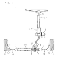
- FIG. is a schematic drawing showing an overall structure of a rack-and-pinion steering apparatus according to the present invention.
- numeral 1 designates a rack shaft, and the rack shaft 1 is movably supported in an axial direction thereof inside a cylindrical rack housing 10, so as to extend in a left and right direction of a vehicle body, which is not shown.
- the respective ends of the rack shaft 1 projecting from both sides of the rack housing 10 are connected to knuckle arms 12, 12 of the left and right front wheels 11, 11, serving as the wheels for steering, via respective tie rods 13, 13.
- a pinion housing 20 is connected such that the central axes intersect with each other, and inside the pinion housing 20 a pinion shaft 2 is pivotably supported around its axis.
- a portion of the pinion shaft 2 projects upward from the pinion housing 20 by an appropriate length, and the tip of the projecting portion is connected to a steering wheel 22, corresponding to the steering member, via a column shaft 21.
- a lower portion of the pinion shaft 2 extending inside the pinion housing 20 includes a larger-diameter portion over an appropriate length, and pinion teeth 4 are provided on an outer circumferential surface of the larger-diameter portion.
- the rack shaft 1 supported inside the rack housing 10 is provided with rack teeth 3 formed over an appropriate length including a portion opposing the pinion shaft 2, and the rack teeth 3 are meshed with the pinion teeth 4 provided on the circumferential surface of the pinion shaft 2.
- Such movement of the rack shaft 1 is transmitted to the left and right knuckle arms 12, 12 via the tie rods 13, 13 connected to the respective ends of the rack shaft 1, so that the knuckle arms 12, 12 push or pull the left and right front wheels 11, 11 so as to steer these wheels in the manipulating direction of the steering wheel 22, by an angle corresponding to the amount of the manipulation.
- the rack-and-pinion steering apparatus shown in FIG. 1 is constituted as an electric power steering apparatus including a motor 5 that assists the steering operation executed as above
- the motor 5 for steering assistance is mounted substantially orthogonally to the column shaft 21, on an outer periphery of a portion close to the lower end of a cylindrical column housing 23 supporting the column shaft 21, and connected to a worm gear reduction apparatus (not shown) disposed inside the column housing 23, so that the rotation of the motor 5 for steering assistance is transmitted to the column shaft 21 through speed reduction by the worm gear reduction apparatus.
- a torque detecting unit 24 that detects the rotating torque (steering torque) applied to the column shaft 21 is disposed at an upper position from the mounting position of the motor 5, and the steering torque detected by the torque detecting unit 24 is utilized for drive control of the motor 5 for steering assistance.
- the steering torque applied to the column shaft 21 is detected by the torque detecting unit 24, and the rotational force of the motor 5 controlled based on the detected torque is applied to the column shaft 21, and then transmitted from the column shaft 21 to the pinion shaft 2, so that an axial moving force is applied to the rack shaft 1, for assisting the steering operation executed as above.
- the feature of the rack-and-pinion steering apparatus according to the present invention lies, as described above, in the configuration of the pinion teeth 4 provided on the pinion shaft 2 which rotates with the manipulating force of the steering wheel 22 and the rotational force of the motor 5 applied thereto.
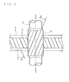
- FIG.2 is an enlarged view showing a portion around the intersection of the rack shaft 1 and the pinion shaft 2.
- the pinion teeth 4 provided on the pinion shaft 2 are formed as helical teeth having a predetermined helix angle 6 with respect to the axial centerline of the pinion shaft 2.
- the rack teeth 3 provided on the rack shaft 1 are formed as skewed teeth inclined by an angle corresponding to the helix angle ⁇ with respect to a direction orthogonal to the axial direction of the rack shaft 1, and meshed with the pinion teeth 4 at the intersection with the pinion shaft 2.
- FIG.3 is a horizontal cross-sectional view showing a mesh portion between the rack teeth 3 and the pinion teeth 4.
- the rack teeth. 3 has, as shown in FIG. 3 , a pressure angle ⁇ , i.e. an angle ⁇ of the tooth surface with respect to the tooth profile direction, and the pressure angle of the pinion teeth 4 meshed with the rack teeth 3 is also ⁇ .
- the rack shaft 1 is biased with pressure toward the pinion shaft 2 by known pressurizing means that utilizes a spring load, so that the rack teeth 3 and the pinion teeth 4 are meshed without backlash, as shown in FIG.3 .
- This can reduce a rattling noise produced by collision of the rack teeth 3 and the pinion teeth 4 at the mesh portion thereof, for example upon switching the steering direction by reverse manipulation of the steering wheel 22, or when a reverse input from the rack shaft 1 is applied.
- pressure angle ⁇ has an upper limit because of processability restriction, and it is difficult to form a pressure angle a exceeding 30°.
- the pressure angle ⁇ of the pinion teeth 4 is selected out of a range of 24° to 30°, which is sufficiently larger than the standard pressure angle stipulated in JIS.
- a stroke ratio S representing a travel amount of the rack shaft 1 per rotation of the pinion shaft 2 is specified, as a requirement from the vehicle on which the steering apparatus is incorporated.
- the stroke ratio S is given from a range of 35 to 60 mm, in ordinary vehicles.
- FIG. 4 is a flowchart showing the selection procedure of the tooth specifications of the pinion teeth 4. For the selection, firstly the pressure angle ⁇ and the stroke ratio S are set (step 1).
- the employable angle is restricted depending on the tooth cutting tool. Accordingly, for example, the foregoing lower limit of 24° is set as the initial value, and the following steps are carried out under different set values at a pitch determined by the restriction of the tool, up to the upper limit of 30°.
- the stroke ratio S although in an actual designing job this is a fixed value provided by the vehicle on which the steering apparatus is mounted as design requirements, herein the following steps are carried out under gradually varying set values of the stroke ratio S between the lower limit of 35 mm and the upper limit of 60 mm, for determining an appropriate range of the module m and the number of teeth z.
- the module m and the number of teeth z of the pinion teeth 4 are calculated based on those set values (step 2).
- the calculation is performed through a known method based on peripheral dimensions such as the outer diameter of the pinion shaft 2 on which the pinion teeth 4 are provided and the center distance between the pinion shaft 2 and the rack shaft 1, and the pressure angle ⁇ and the stroke ratio S, such that the module m and the number of teeth z are specified in combinations of a plurality of numbers of teeth z that are only integers, and the corresponding module m.
- a plurality of helix angle values B of the pinion teeth 4 is set within a range under a predetermined upper limit angle (step 3), and a plurality tooth depth values h is set within a predetermined range including the module m (step 4).
- the upper limit angle of the helix angle ⁇ which is determined by the thrust load capacity of the bearing supporting the pinion shaft 2 provided with the pinion teeth 4 inside the pinion housing 20, is usually set at around 40°.
- the helix angle ⁇ is determined in a range of 30° to 35° which is close to the upper limit, because when the helix angle ⁇ is smaller, the length of the path of contact along the tooth trace direction between the pinion teeth 4 and the rack teeth 3 becomes short, which makes it difficult to satisfy the strength condition to be subsequently described, herein the helix angle ⁇ is set over the entire range from the upper limit angle of 40° to the lower limit angle of 0°, in order to determine an appropriate range of the module m and the number of teeth z, for executing the following steps.
- step 5 predetermined geometrical requirements
- step 6 predetermined strength requirements
- step 7 predetermined strength requirements
- One of the geometrical requirements serving as the criterion at the step 5 is whether the pinion teeth 4 and the rack teeth 3 can he meshed without interference, and another is whether the addendum of the pinion teeth 4 is provided with a sufficient tooth thickness.
- the former i.e. the meshing status is judged for example based on whether a trochoid interference clearance of 0.3 mm or more is secured upon calculation hy the following equation.
- X designates an addendum modification coefficient, given as a value obtained by dividing the addendum modification specified for the pinion teeth 4 with the module m.
- t stands for the trochoid interference clearance, serving as the index indicating whether a phenomenon that the tooth tip of a rack tooth 3 that has passed the predetermined meshing position interferes with the dedendum of a pinion tooth 4 as if gouging out the same under the meshing status of the rack teeth 3 and the pinion teeth 4 as shown in FIG.3 , i.e. what is known as trochoid interference, takes place.
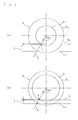
- FIGS. 5(a) and 5(b) are diagrams for explaining the trochoid interference clearance.
- P 1 designates a base circle of the pinion teeth 4
- P 2 designates an addendum circle of the pinion teeth 4
- R 1 designates a base circle of the rack teeth 3
- R 2 designates an addendum circle of the rack teeth 3.
- ⁇ bs stands for a working pressure angle
- the working pressure angle ⁇ bs at the mesh portion between the rack teeth 3 and the pinion teeth 4 is equal to the pressure angle ⁇ of the rack teeth 3 and the pinion teeth 4.
- FIG. 5(a) depicts a case where a difference in diameter between the base circle P 1 and the addendum circle P 2 of the pinion teeth 4 is large
- FIG. 5(b) depicts a case where the difference in diameter is small.
- the trochoid interference clearance t is given as a distance between a point a where a contact line b inclined by the working pressure angle ⁇ bs toward a side of the contact center line intersects with the base circle P 1 of the pinion teeth 4 and the addendum circle R 2 of the rack teeth 3.
- the intersection point a in FIG.5(a) is located at an inner position (on the dedendum side) from the addendum circle R 2 of the rack teeth 3
- the intersection point a in FIG.5(b) is located at an outer position from the addendum circle R 2 of the rack teeth 3, and therefore the trochoid interference between the rack teeth 3 and the pinion teeth 4 takes place under the state shown in FIG.5(a) .
- the trochoid interference clearance t obtained by the equation (1) becomes negative under the state shown in FIG. 5(a) and becomes positive under the state shown in FIG. 5(b) , according to the geometrical positional relation between the rack teeth 3 and the pinion teeth 4 shown in FIGS. 5(a) and 5(b) , and at the step 5 the pressure angle ⁇ , the helix angle ⁇ , the module in and the number of teeth z, which are set as above, are substituted in the equation (1) to sequentially calculate the trochoid interference clearance t, to thereby decide that the meshing may be executed provided that the calculated value turns out to be 0.3 mm or more, as already stated.
- a purpose of setting the lower limit of the trochoid interference clearance t at 0.3 mm is to eliminate an influence of a processing error of the pinion teeth 4 and the rack teeth 3, and also an influence of distortion that emerges on the pinion teeth 4 or the rack teeth 3, during the foregoing operation.
- the latter condition i.e.. whether the tooth thickness of the addendum is acceptable, is provided for preventing excessive hardening in a heat treatment after a teeth cutting process, and may be decided, for example, depending on whether the tooth thickness (in a direction perpendicular to the tooth profile) S kn of the addendum of the pinion teeth 4 calculated by the following equations is 0.3m (m designates the module), which is employed as a threshold value in the designing of force transmitting gears.
- s k designates a transverse tooth thickness of the pinion teeth 4; rk designates an addendum circle radius of the pinion teeth 4; and ⁇ k designates a helix angle of the pinion teeth 4 on the addendum circle.
- ⁇ ks stands for a gear rotation angle corresponding to the tooth tip position, and ⁇ s designates a pressure angle on the standard pitch circle, which can be obtained through the following equations.
- r g designates a base circle radius of the pinion teeth 4.
- the pressure angle ⁇ , the number of teeth z and the helix angle ⁇ , which are set as above, are substituted in the equations (2), (3), and (4) to sequentially calculate the tooth thickness (in a direction perpendicular to the tooth profile) s kn of the addendum of the pinion teeth 4, to thereby decide that the tooth thickness of the addendum is acceptable provided that the calculated value turns out to be 0.3m or more, as already stated.
- one of the strength requirements serving as the criterion for the decision is the bending strength of the dedendum of the pinion teeth 4, and another is the fatigue strength of the tooth surface.
- the bending strength of the dedendum is evaluated with the following equation (Lewis equation) employed for calculation of bending stress of o B of a spur gear.
- ⁇ B F N ⁇ h F ⁇ cos ⁇ s F b 2 6
- F N designates a tooth surface normal load, given as a designing condition from the vehicle on which the rack-and-pinion steering apparatus is to be mounted.
- ⁇ in the equation represents a complementary angle of an angle defined by the load line and the tooth profile center line;
- h F represents a distance from the intersection point of the load line and the tooth profile center line to the critical section;
- s F represents a tooth thickness of the critical section, which can be obtained by the following equations, when the pinion teeth 4 are skewed teeth.
- ⁇ 0 in these equations represents a pressure angle of the tool; ⁇ 0 represents a radius of an addendum profile of the tool; h a represents the tooth depth of the addendum; and 0 can be obtained from the following equations.
- the fatigue strength of the tooth surface is evaluated based on the tooth surface contact stress ⁇ H obtained by the following equation, applying the elastic contact theory of Hertz.
- ⁇ H 0.35 ⁇ E ⁇ P n ⁇ z 1 + z 2 z 2 ⁇ cos 2 ⁇ ⁇ g N b ⁇ ⁇ s ⁇ b ⁇ d b ⁇ sin ⁇ bs
- P n represents a tangent load perpendicular to the tooth and d b represents a working pitch circle diameter of the smaller gear, each of which can be obtained from the following equations.
- the tooth specifications for the pinion teeth 4 that enable smooth meshing and provides a sufficient bending strength and fatigue strength can be determined, with a pressure angle ⁇ within a range of 24° to 30° and an ordinary stroke ratio S within a range of 35 to 60 mm, and such tooth specifications can be defined as follows:
- the optimum tooth specifications for the pinion teeth 4 are determined as 1.8 mm for the module m, and 7 for the number of teeth z, as shown in FIG.3 .
- the module m is smaller but the number of teeth z is greater, and thus a larger number of small-sized pinion teeth 4 are provided.
- the rotating torque stands for the meshing friction between the rack teeth 3 and the pinion teeth 4, and hence it is obvious that the rack-and-pinion steering apparatus according to the present invention can significantly reduce the meshing friction, even taking into account some error in condition setting for the experiments, thereby allowing a reaction force from the road surface to propagate directly to the driver manipulating the steering wheel 22 thereby achieving, for example, improvement in steering feeling when driving at a high speed on a low- ⁇ road that provides only a small reaction force from the road surface
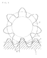
- FIG.6 is a schematic drawing for explaining desirable tooth surface modification.
- FIG. 6 depicts the tooth surface of the pinion teeth 4 divided in a mesh pattern in vertical and horizontal directions.
- a negative pressure angle error is set in a direction of the tooth profile, such that the pressure angle of the addendum is made larger than the pressure angle of the dedendum, i.e. the pressure angle error in such a direction that increases the mesh stress with the rack teeth 3, and besides such tooth surface modification is applied as forming a central portion thereof in a convex shape, and crowning along a direction of the tooth trace.
- Such tooth surface modification enables leveling off distribution of the contact stress on the surface of the pinion teeth 4 in a direction of the tooth trace as well as in a direction of the tooth profile, thereby preventing uneven abrasion of the tooth surface thus to compensate the shortage in strength of the dedendum, which results in improved durability. It is to be noted that in the pinion teeth 4 according to the foregoing tooth specifications, an appropriate amount of the crowning is approximately 10 ⁇ m at maximum at a central portion, and an appropriate error of the tooth thickness is approximately 20 ⁇ m at maximum at the addendum.
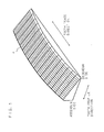
- FIG.7 is a graph showing a result of measurement of abrasion loss of the surface of the pinion teeth 4 after executing the predetermined durability test, carried out for examining the effect of the tooth surface modification.
- White bars in FIG. 7 represent the result obtained after the foregoing tooth surface modification; hatched bars in FIG. 7 represent the result obtained without the tooth surface modification respectively; and cross-hatched bars in FIG. 7 represent the result obtained after the tooth surface modification only including the crowning in the direction of the tooth trace.
- Three bar groups on the left side in FIG. 7 indicate the abrasion loss distribution in the direction of the tooth trace in the vicinity of the base circle, and the measured values with respect to the vicinity of the line of tooth bearing on the tip portion side of the pinion shaft 2, the vicinity of the central portion of the pinion shaft 2 in the direction of the tooth trace, and the vicinity of the line of tooth bearing on the base portion side of the pinion shaft 2, in order from the left respectively.
- Two bar groups on the right side in FIG. 7 indicate the abrasion loss distribution in the direction of the tooth profile, such that left group represents the measured value with respect to the vicinity of the addendum, while the right group represents the measured value with respect to a substantially central portion in the direction of the tooth profile.
- a negative pressure angle error is granted, i.e. the pressure angle of the addendum is made larger than the pressure angle of the dedendum, for providing the pressure angle error oriented so as to increase the mesh stress in the direction of the tooth profile between the rack teeth 3 and the pinion teeth 4, granting a positive pressure angle error, i.e. making the pressure angle of the dedendum larger than the pressure angle of the addendum can also increase the mesh stress.
- the forgoing embodiment refers to application of the rack-and-pinion steering apparatus to the electric power steering apparatus including the motor for steering assistance between the steering member and the pinion shaft, so as to transmit the rotational force of the motor to the pinion shaft thus to assist the steering operation performed based on the rotation of the pinion shaft, i.e.
- the rack-and pinion steering apparatus may be structured as a different type electric power steering apparatus, or as a manual steering apparatus that executes the steering operation only with the steering torque applied by the driver via the steering wheel 22 serving as the steering member, and further as a hydraulic power steering apparatus that applies to the rack shaft 1 a force generated by a hydraulic cylinder disposes halfway of the rack housing 10, thus to assist the steering operation.
Landscapes
- Engineering & Computer Science (AREA)
- General Engineering & Computer Science (AREA)
- Mechanical Engineering (AREA)
- Chemical & Material Sciences (AREA)
- Combustion & Propulsion (AREA)
- Transportation (AREA)
- Power Steering Mechanism (AREA)
- Transmission Devices (AREA)
- Gears, Cams (AREA)
Applications Claiming Priority (2)
| Application Number | Priority Date | Filing Date | Title |
|---|---|---|---|
| JP2004006094A JP4419574B2 (ja) | 2004-01-13 | 2004-01-13 | ラックピニオン式操舵装置 |
| PCT/JP2005/000251 WO2005068878A1 (ja) | 2004-01-13 | 2005-01-12 | ラックピ二オン式操舵装置 |
Publications (3)
| Publication Number | Publication Date |
|---|---|
| EP1731799A1 EP1731799A1 (en) | 2006-12-13 |
| EP1731799A4 EP1731799A4 (en) | 2011-05-04 |
| EP1731799B1 true EP1731799B1 (en) | 2012-03-14 |
Family
ID=34792126
Family Applications (1)
| Application Number | Title | Priority Date | Filing Date |
|---|---|---|---|
| EP05703490A Ceased EP1731799B1 (en) | 2004-01-13 | 2005-01-12 | Rack and pinion-type steering device |
Country Status (4)
| Country | Link |
|---|---|
| US (1) | US8683887B2 (enExample) |
| EP (1) | EP1731799B1 (enExample) |
| JP (1) | JP4419574B2 (enExample) |
| WO (1) | WO2005068878A1 (enExample) |
Cited By (1)
| Publication number | Priority date | Publication date | Assignee | Title |
|---|---|---|---|---|
| CN108167416A (zh) * | 2017-11-15 | 2018-06-15 | 山东农业大学 | 一种变比转向器变厚齿扇齿条副中变比齿条的建模方法 |
Families Citing this family (22)
| Publication number | Priority date | Publication date | Assignee | Title |
|---|---|---|---|---|
| JP4419574B2 (ja) | 2004-01-13 | 2010-02-24 | 株式会社ジェイテクト | ラックピニオン式操舵装置 |
| US8517884B2 (en) * | 2006-03-24 | 2013-08-27 | Gkn Sinter Metals, Llc | Powder forged differential gear |
| WO2008069172A1 (ja) * | 2006-12-05 | 2008-06-12 | Thk Co., Ltd. | ボールねじを用いたステアリング装置 |
| JP2009160960A (ja) * | 2007-12-28 | 2009-07-23 | Nsk Ltd | ラック・アンド・ピニオン式ステアリング装置 |
| US8181549B2 (en) | 2008-04-03 | 2012-05-22 | Honda Motor Co., Ltd. | Steering apparatus |
| JP5273460B2 (ja) * | 2008-11-28 | 2013-08-28 | 株式会社ジェイテクト | 操舵機構の設計方法 |
| KR101685422B1 (ko) * | 2011-05-30 | 2016-12-12 | 한화테크윈 주식회사 | 촬상 장치 지지용 조립체 |
| US9512898B2 (en) * | 2011-12-06 | 2016-12-06 | Honda Motor Co., Ltd. | Worm gear mechanism |
| DE102011089021A1 (de) * | 2011-12-19 | 2013-06-20 | Zf Friedrichshafen Ag | Getriebevorrichtung mit einem innenverzahnten Hohlrad sowie zwei damit kämmenden Stirnrädern |
| JP5880155B2 (ja) * | 2012-03-08 | 2016-03-08 | 株式会社ジェイテクト | ステアリング装置 |
| JP2014016000A (ja) * | 2012-07-10 | 2014-01-30 | Nsk Ltd | 動力伝達部材 |
| SG2012086039A (en) | 2012-11-22 | 2014-06-27 | Cal Comp Prec Singapore Ltd | Scan mechanism and scan module |
| US9145956B2 (en) | 2013-01-25 | 2015-09-29 | Gustomsc Resources B.V. | Torque sharing drive and torque sharing process |
| US9531237B2 (en) | 2013-12-19 | 2016-12-27 | Gustomsc Resources B.V. | Dual rack output pinion drive |
| IN2013MU04054A (enExample) * | 2013-12-25 | 2015-07-31 | Rotex Manufacturers And Engineers Private Ltd | |
| JP6555210B2 (ja) * | 2016-08-09 | 2019-08-07 | トヨタ自動車株式会社 | 歯車機構およびその製造方法 |
| US10150498B2 (en) * | 2016-08-10 | 2018-12-11 | Jtekt Corporation | Steering system |
| ES2858073T3 (es) | 2017-05-24 | 2021-09-29 | Ims Gear Se & Co Kgaa | Par de ruedas dentadas para un engranaje helicoidal, engranaje helicoidal con un par de ruedas dentadas de este tipo, así como uso de un par de ruedas dentadas de este tipo en engranajes helicoidales |
| EP3406939B1 (de) * | 2017-05-24 | 2020-04-01 | IMS Gear SE & Co. KGaA | Zahnradpaarung für ein schraubradgetriebe oder ein stirnradgetriebe, schraubradgetriebe oder stirnradgetriebe mit einer derartigen zahnradpaarung sowie verwendung einer derartigen zahnradpaarung in schraubradgetrieben und stirnradgetrieben |
| CN112664629A (zh) * | 2019-10-15 | 2021-04-16 | 雅邦企业股份有限公司 | 低噪音升降调整装置 |
| CN110805680B (zh) * | 2019-10-29 | 2021-02-02 | 西安交通大学 | 一种高强度齿轮齿根过渡曲线的优化方法 |
| JP7762082B2 (ja) * | 2022-01-26 | 2025-10-29 | Nskステアリング&コントロール株式会社 | 電動パワーステアリング装置、および、電動パワーステアリング装置用ラック軸 |
Family Cites Families (17)
| Publication number | Priority date | Publication date | Assignee | Title |
|---|---|---|---|---|
| FR2293642A1 (fr) | 1974-12-04 | 1976-07-02 | Rouverol William | Engrenage a couple moteur eleve |
| JPS5631551A (en) | 1979-08-20 | 1981-03-30 | Honda Motor Co Ltd | Combination mechanism of rack and pinion |
| JPS626925Y2 (enExample) | 1981-01-12 | 1987-02-18 | ||
| JPS63180766A (ja) | 1987-01-23 | 1988-07-25 | Toyota Motor Corp | 歯形修正歯車 |
| JP2836426B2 (ja) | 1993-03-26 | 1998-12-14 | 株式会社日立製作所 | 遊星歯車装置及び増減速歯車装置 |
| JPH09133187A (ja) | 1995-11-10 | 1997-05-20 | Toyota Central Res & Dev Lab Inc | 3軸歯車装置及び歯車装置 |
| JP3552234B2 (ja) * | 1996-10-02 | 2004-08-11 | トヨタ自動車株式会社 | 歯車設計方法、歯車製造方法、およびその製造方法で製造された歯車 |
| JP3133005B2 (ja) * | 1996-12-25 | 2001-02-05 | 加茂精工株式会社 | 回転運動と直線運動の変換装置 |
| JP2000130560A (ja) | 1998-10-27 | 2000-05-12 | Fuji Kiko Co Ltd | 少歯数サイクロイド歯車 |
| JP2000211535A (ja) | 1999-01-21 | 2000-08-02 | Kayaba Ind Co Ltd | ラックピニオン式ステアリング装置 |
| JP2001163228A (ja) | 1999-12-07 | 2001-06-19 | Honda Motor Co Ltd | 電動パワーステアリング装置 |
| JP2004001679A (ja) | 2001-12-03 | 2004-01-08 | Nsk Ltd | 電動式パワーステアリング装置 |
| JP3800145B2 (ja) * | 2002-07-30 | 2006-07-26 | トヨタ自動車株式会社 | 車両操舵装置 |
| JP4414688B2 (ja) | 2003-06-26 | 2010-02-10 | 株式会社ジェイテクト | 歯車機構 |
| JPWO2005056367A1 (ja) | 2003-12-08 | 2007-12-06 | 株式会社ジェイテクト | 電動パワーステアリング装置 |
| JP4419574B2 (ja) | 2004-01-13 | 2010-02-24 | 株式会社ジェイテクト | ラックピニオン式操舵装置 |
| JP6238579B2 (ja) | 2013-06-06 | 2017-11-29 | デンカ株式会社 | 炭酸化建材用の結合材およびその製造方法。 |
-
2004
- 2004-01-13 JP JP2004006094A patent/JP4419574B2/ja not_active Expired - Fee Related
-
2005
- 2005-01-12 US US10/585,759 patent/US8683887B2/en not_active Expired - Fee Related
- 2005-01-12 EP EP05703490A patent/EP1731799B1/en not_active Ceased
- 2005-01-12 WO PCT/JP2005/000251 patent/WO2005068878A1/ja not_active Ceased
Cited By (2)
| Publication number | Priority date | Publication date | Assignee | Title |
|---|---|---|---|---|
| CN108167416A (zh) * | 2017-11-15 | 2018-06-15 | 山东农业大学 | 一种变比转向器变厚齿扇齿条副中变比齿条的建模方法 |
| CN108167416B (zh) * | 2017-11-15 | 2019-08-02 | 山东农业大学 | 一种变厚齿扇齿条副中变比齿条的建模方法 |
Also Published As
| Publication number | Publication date |
|---|---|
| JP2005199776A (ja) | 2005-07-28 |
| JP4419574B2 (ja) | 2010-02-24 |
| US8683887B2 (en) | 2014-04-01 |
| EP1731799A1 (en) | 2006-12-13 |
| EP1731799A4 (en) | 2011-05-04 |
| US20080223163A1 (en) | 2008-09-18 |
| WO2005068878A1 (ja) | 2005-07-28 |
Similar Documents
| Publication | Publication Date | Title |
|---|---|---|
| EP1731799B1 (en) | Rack and pinion-type steering device | |
| US7654167B2 (en) | Electric power steering apparatus equipped with worm gear mechanism | |
| EP1767436B1 (en) | Electric power steering device | |
| US9512898B2 (en) | Worm gear mechanism | |
| CN117208079A (zh) | 转向架及其制造方法 | |
| US7520366B2 (en) | Method for producing electric power steering apparatus | |
| JP5172754B2 (ja) | 電動パワーステアリング装置 | |
| JP4361350B2 (ja) | 車両用歯車機構 | |
| EP1702830B1 (en) | Electric power steering device | |
| EP1547904B1 (en) | Method of manufacturing rack shaft | |
| US11781633B2 (en) | Rack bar and steering apparatus | |
| EP1757842A1 (en) | Pinion shaft | |
| JP4957964B2 (ja) | 電動パワーステアリング装置 | |
| JPWO2005017393A1 (ja) | 減速装置及び該減速装置を製造する方法及び装置、及び該減速装置を備えた電動式パワーステアリング装置 | |
| JP2005125972A (ja) | ラックアンドピニオン式ステアリング装置 | |
| KR100794456B1 (ko) | 피스톤랙의 강도가 보강된 파워스티어링장치 | |
| KR101104498B1 (ko) | 랙바의 비틀림이 방지되는 자동차의 조향장치 | |
| JP2005035513A (ja) | 電動パワーステアリング装置 | |
| JP2007090968A (ja) | ラックアンドピニオン式電動パワーステアリング装置 | |
| KR20110125339A (ko) | 랙바와 이 랙바를 구비한 조향장치 및 랙바의 제조방법 | |
| JP2012163179A (ja) | 減速機構および電動パワーステアリング装置 | |
| JP2016223595A (ja) | ウオームホイール |
Legal Events
| Date | Code | Title | Description |
|---|---|---|---|
| PUAI | Public reference made under article 153(3) epc to a published international application that has entered the european phase |
Free format text: ORIGINAL CODE: 0009012 |
|
| 17P | Request for examination filed |
Effective date: 20060727 |
|
| AK | Designated contracting states |
Kind code of ref document: A1 Designated state(s): DE FR GB |
|
| DAX | Request for extension of the european patent (deleted) | ||
| RBV | Designated contracting states (corrected) |
Designated state(s): DE FR GB |
|
| A4 | Supplementary search report drawn up and despatched |
Effective date: 20110406 |
|
| GRAP | Despatch of communication of intention to grant a patent |
Free format text: ORIGINAL CODE: EPIDOSNIGR1 |
|
| RIC1 | Information provided on ipc code assigned before grant |
Ipc: B62D 5/22 20060101ALI20110707BHEP Ipc: F16H 19/04 20060101ALI20110707BHEP Ipc: F16H 55/08 20060101AFI20110707BHEP Ipc: B62D 5/04 20060101ALI20110707BHEP Ipc: B62D 3/12 20060101ALI20110707BHEP |
|
| GRAS | Grant fee paid |
Free format text: ORIGINAL CODE: EPIDOSNIGR3 |
|
| GRAA | (expected) grant |
Free format text: ORIGINAL CODE: 0009210 |
|
| AK | Designated contracting states |
Kind code of ref document: B1 Designated state(s): DE FR GB |
|
| REG | Reference to a national code |
Ref country code: GB Ref legal event code: FG4D |
|
| REG | Reference to a national code |
Ref country code: DE Ref legal event code: R096 Ref document number: 602005033139 Country of ref document: DE Effective date: 20120510 |
|
| PLBE | No opposition filed within time limit |
Free format text: ORIGINAL CODE: 0009261 |
|
| STAA | Information on the status of an ep patent application or granted ep patent |
Free format text: STATUS: NO OPPOSITION FILED WITHIN TIME LIMIT |
|
| 26N | No opposition filed |
Effective date: 20121217 |
|
| REG | Reference to a national code |
Ref country code: DE Ref legal event code: R097 Ref document number: 602005033139 Country of ref document: DE Effective date: 20121217 |
|
| GBPC | Gb: european patent ceased through non-payment of renewal fee |
Effective date: 20130112 |
|
| PG25 | Lapsed in a contracting state [announced via postgrant information from national office to epo] |
Ref country code: GB Free format text: LAPSE BECAUSE OF NON-PAYMENT OF DUE FEES Effective date: 20130112 |
|
| REG | Reference to a national code |
Ref country code: FR Ref legal event code: PLFP Year of fee payment: 12 |
|
| REG | Reference to a national code |
Ref country code: FR Ref legal event code: PLFP Year of fee payment: 13 |
|
| REG | Reference to a national code |
Ref country code: FR Ref legal event code: PLFP Year of fee payment: 14 |
|
| PGFP | Annual fee paid to national office [announced via postgrant information from national office to epo] |
Ref country code: FR Payment date: 20201210 Year of fee payment: 17 |
|
| PGFP | Annual fee paid to national office [announced via postgrant information from national office to epo] |
Ref country code: DE Payment date: 20201229 Year of fee payment: 17 |
|
| REG | Reference to a national code |
Ref country code: DE Ref legal event code: R119 Ref document number: 602005033139 Country of ref document: DE |
|
| PG25 | Lapsed in a contracting state [announced via postgrant information from national office to epo] |
Ref country code: DE Free format text: LAPSE BECAUSE OF NON-PAYMENT OF DUE FEES Effective date: 20220802 |
|
| PG25 | Lapsed in a contracting state [announced via postgrant information from national office to epo] |
Ref country code: FR Free format text: LAPSE BECAUSE OF NON-PAYMENT OF DUE FEES Effective date: 20220131 |