EP1724388A1 - Bügelmaschine - Google Patents
Bügelmaschine Download PDFInfo
- Publication number
- EP1724388A1 EP1724388A1 EP06007555A EP06007555A EP1724388A1 EP 1724388 A1 EP1724388 A1 EP 1724388A1 EP 06007555 A EP06007555 A EP 06007555A EP 06007555 A EP06007555 A EP 06007555A EP 1724388 A1 EP1724388 A1 EP 1724388A1
- Authority
- EP
- European Patent Office
- Prior art keywords
- laundry
- bulges
- storage surface
- storage
- hexagonal
- Prior art date
- Legal status (The legal status is an assumption and is not a legal conclusion. Google has not performed a legal analysis and makes no representation as to the accuracy of the status listed.)
- Granted
Links
Images

Classifications
-
- D—TEXTILES; PAPER
- D06—TREATMENT OF TEXTILES OR THE LIKE; LAUNDERING; FLEXIBLE MATERIALS NOT OTHERWISE PROVIDED FOR
- D06F—LAUNDERING, DRYING, IRONING, PRESSING OR FOLDING TEXTILE ARTICLES
- D06F67/00—Details of ironing machines provided for in groups D06F61/00, D06F63/00, or D06F65/00
Definitions
- the invention relates to a storage surface for emerging on the laundry output side of an ironing machine lacked laundry.
- From the DE 44 31 590 A1 is an ironing machine with a structured trained investment board for the laundry input side known.
- the structure in the guiding direction of the deficiency washing structure on the investment board should support the sliding behavior of the wet laundry when entering laundry in the direction of ironing roller and at the same time avoid slipping of the laundry items.
- Such a corrugated structure is not suitable for the design of the shelf on the laundry output side.
- a corrugated structure on the laundry output side is transferred into the still moist warm laundry items due to the weight of the laundry or stamped in this.
- condensate collects in the recesses of the structured surface and increases the rewetting of the laundry.
- the invention thus raises the problem of improving the sliding behavior of the laundry items on the laundry output side and to avoid rewetting the laundry.
- the achievable with the present invention consist in particular that arranged by the special design of the shelf with evenly distributed on the surface arranged bulges and arranged in the edge region of the vaults the otherwise often required hanging the laundry after mangling to evaporate the residual moisture can be omitted.
- the still moist warm laundry exits between the trough and the ironing roller and slides over the arched storage surface.
- the damp, still warm laundry has a thermal effect so that cool dry room air passes through the holes from below, thus cooling the laundry and taking the residual moisture out of the laundry in the air stream.
- the cooling process evaporates residual moisture on the shelf without rewetting.
- the partial resting of the laundry on the bulges also causes an improved sliding behavior of the laundry on the laundry output side. This prevents the laundry from accumulating on the shelf or wrinkling. A renewed creasing is thus prevented.
- the curvatures are designed as a hexagonal embossed structure aligned in the direction of the laundry.
- a single curvature is formed in the manner of a flat bump with a hexagonal base, with their dome forms a partial bearing surfaces for the laundry and thereby supports the slipping of the laundry.
- the holes are arranged at the edge of the base so that the overlying laundry can not close the air inlet openings. Such an arrangement of the holes supports the flow of air, which flows due to the thermal effect of still moist warm laundry from below through the laundry and entrains the residual moisture.
- the storage surface is designed in several parts. Several individual segments form interconnected via connecting elements a large storage area.
- storage areas of variable size can be adapted for different ironing roller dimensions of the ironing machines. As a result, even large storage areas can be better transported.
- the ironing machine with the heatable ironing 1 is shown schematically in the side view.
- the ironing machine has on the laundry input page E a conditioning board 3.
- On the laundry output side A of the ironing roller 2 is associated with a stripper 4, which strips the mangled laundry from the ironing roller 2 and passes to the storage surface 5.
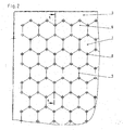
- the surface of the depositing surface 5 is shown in sections with bulges 6 distributed uniformly over the surface.
- a single curvature 6 is formed in the manner of a flat bump with a hexagonal base surface whose dome 7 forms a partial support surfaces for the laundry.
- holes 8 are arranged.
- the storage surface 5 is formed in the embodiment shown here with polygonal vaults 6 in the manner of a honeycomb-shaped arch structure. The vaults 6 and the crests 7 of the bulges are aligned in the direction of the laundry.
- the contiguous curvature edges of the hexagonal embossed structure are slightly deeper.
- the holes 8 are arranged in the corner points of the hexagonal curvature edges.
- it is also possible to form the surface of the storage surface with bulges e.g. have circular bases.
- the bumps can also be arranged at a distance from each other, the holes are then to be arranged in the intermediate between slightly lower areas.
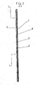
- FIG 3 shows a section through the support surface 5, in which the air flow L, which due to the thermal effect of the wet still warm laundry W flows from below through the holes 8, is indicated.
- the storage surface is formed in several parts. Several individual segments form interconnected via connecting elements a large storage area.
Landscapes
- Engineering & Computer Science (AREA)
- Textile Engineering (AREA)
- Accessory Of Washing/Drying Machine, Commercial Washing/Drying Machine, Other Washing/Drying Machine (AREA)
- Treatment Of Fiber Materials (AREA)
- Irons (AREA)
- Iron Core Of Rotating Electric Machines (AREA)
Abstract
Description
- Die Erfindung betrifft eine Ablagefläche für die auf der Wäscheausgabeseite einer Bügelmaschine austretende gemangelte Wäsche.
- Aus der
DE 43 39 601 C2 ist es bekannt, auf der Wäscheausgabeseite einer Bügelmaschine eine Abgabevorrichtung mit einer Ablagefläche für die gemangelte Wäsche anzuordnen. Diese Bügelmaschine weist eine beheizte Bügelmulde sowie eine drehbar gelagerte Bügelwalze auf. Die gemangelte Wäsche wird aus dem Muldenaustritt heraus auf die Ablagefläche geführt. - Durch das Aufliegen der noch feuchten warmen Wäsche auf der Ablagefläche kann die Restfeuchtigkeit aus der gemangelten Wäsche an der Ablagefläche kondensieren. Dies führt zu einer Rückbefeuchtung der Wäsche. Eine glatte Ablagefläche hat außerdem den Nachteil, dass noch leicht feuchte Wäschestücke nicht einwandfrei auf der Ablagefläche abgleiten. Die Wäsche legt sich auf dem Ablagetisch in Falten und es kann zu erneuter Knitterbildung kommen.
- Aus der
DE 44 31 590 A1 ist eine Bügelmaschine mit einem strukturiert ausgebildeten Anlagebrett für die Wäscheeingabeseite bekannt. Die in Führungsrichtung der Mangelwäsche ausgerichtete Struktur am Anlagebrett soll das Gleitverhalten der feuchten Wäsche bei der Wäscheeingabe in Richtung Bügelwalze unterstützen und gleichzeitig ein Abrutschen der Wäschestücke vermeiden. Eine derartige geriffelte Struktur ist für die Gestaltung der Ablagefläche auf der Wäscheausgabeseite nicht geeignet. Eine geriffelte Struktur auf der Wäscheausgabeseite wird in die noch feuchten warmen Wäschestücke bedingt durch das Eigengewicht der Wäsche übertragen bzw. in diese geprägt. Außerdem sammelt sich in den Vertiefungen der strukturierten Oberfläche Kondensat und erhöht das Rückbefeuchten der Wäsche. - Der Erfindung stellt sich somit das Problem, das Gleitverhalten der Wäschestücke auf der Wäscheausgabeseite zu verbessern und ein Rückbefeuchten der Wäsche zu vermeiden.
- Erfindungsgemäß wird dieses Problem durch eine Ablagefläche mit den Merkmalen des Patentanspruchs 1 gelöst. Vorteilhafte Ausgestaltungen und Weiterbildungen der Erfindung ergeben sich aus den nachfolgenden Unteransprüchen.
- Die mit der Erfindung erreichbaren Vorteile bestehen insbesondere darin, dass durch die besondere Ausbildung der Ablagefläche mit gleichmäßig auf der Oberfläche verteilt angeordneten Wölbungen und im Randbereich der Wölbungen angeordneten Bohrungen das sonst oft erforderliche Aufhängen der Wäsche nach dem Mangeln zum Abdampfen der Restfeuchtigkeit entfallen kann. Die noch feuchte warme Wäsche tritt zwischen Mulde und Bügelwalze aus und gleitet über die mit Wölbungen ausgebildete Ablagefläche. Die feuchte noch warme Wäsche hat eine Thermikwirkung so dass von unten kühle trockene Raumluft durch die Bohrungen durchtritt und so die Wäsche abkühlt und die Restfeuchtigkeit aus der Wäsche im Luftstrom mitnimmt. Durch den Abkühlprozess wird Restfeuchtigkeit auf der Ablagefläche ohne Rückbefeuchtung abgedampft.
- Das partielle Aufliegen der Wäsche auf den Wölbungen bewirkt außerdem ein verbessertes Gleitverhalten der Wäsche auf der Wäscheausgabeseite. Dadurch wird verhindert, dass sich die Wäsche auf der Ablagefläche aufstaut bzw. in Falten legt. Eine erneute Knitterbildung wird somit verhindert.
- Es ist vorteilhaft, die Ablagefläche mit vieleckigen Wölbungen in der Art einer wabenförmig ausgebildeten Wölbstruktur auszubilden. Die Bohrungen sind in einer vorteilhaften Weiterbildung in den Eckpunkten der hexagonalen Wölbungsränder angeordnet.
- In einer vorteilhaften Weiterbildung sind die Wölbungen als in Richtung der Wäsche ausgerichtete hexagonal geprägte Struktur ausgebildet. Eine einzelne Wölbung ist in der Art einer flachen Beule mit sechseckiger Grundfläche ausgebildet, wobei deren Kuppe eine partielle Auflageflächen für die Wäsche bildet und dadurch das Abgleiten der Wäsche unterstützt. Die Bohrungen sind am Rand der Grundfläche angeordnet, so dass die aufliegende Wäsche die Lufteintrittsöffnungen nicht verschließen kann. Eine derartige Anordnung der Bohrungen unterstützt den Luftstrom, welcher bedingt durch die Thermikwirkung der noch feuchten warmen Wäsche von unten durch die Wäsche strömt und die Restfeuchtigkeit mitnimmt.
- In einer vorteilhaften Ausgestaltung der Erfindung ist die Ablagefläche mehrteilig ausgebildet. Mehrere Einzelsegmente bilden über Verbindungselemente miteinander verbunden eine großflächige Ablagefläche. Durch die modulartigen Segmente können Ablageflächen variabler Größe für unterschiedliche Bügelwalzenmaße der Bügelmaschinen angepasst werden. Dadurch lassen sich auch großflächige Ablageflächen besser transportieren.
- Ein Ausführungsbeispiel der Erfindung ist in den Zeichnungen rein schematisch dargestellt und wird nachfolgend näher beschrieben. Es zeigen:
- Figur 1
- eine Bügelmaschine schematisch in der Seitenansicht mit daran angeordneter Ablagefläche;
- Figur 2
- die Oberfläche der Ablagefläche ausschnittsweise in Blickrichtung X und
- Figur 3
- einen Schnitt durch die Ablagefläche gemäß Schnittlinie A - A.
- In der Figur 1 ist die Bügelmaschine mit der beheizbaren Bügelmulde 1 in der Seitenansicht schematisch dargestellt. In der Bügelmulde 1 läuft die drehbar gelagerte Bügelwalze 2. Die Bügelmaschine weist auf der Wäscheeingabeseite E ein Anlagebrett 3 auf. Auf der Wäscheausgabeseite A ist der Bügelwalze 2 ein Abstreifer 4 zugeordnet, der die gemangelte Wäsche von der Bügelwalze 2 abstreift und auf die Ablagefläche 5 leitet.
- In der Figur 2 ist die Oberfläche der Ablagefläche 5 mit gleichmäßig auf der Oberfläche verteilt angeordneten Wölbungen 6 ausschnittsweise dargestellt. Eine einzelne Wölbung 6 ist in der Art einer flachen Beule mit sechseckiger Grundfläche ausgebildet wobei deren Kuppe 7 eine partielle Auflageflächen für die Wäsche bildet. Im Randbereich der Wölbungen sind Bohrungen 8 angeordnet. Die Ablagefläche 5 ist bei dem hier dargestellten Ausführungsbeispiel mit vieleckigen Wölbungen 6 in der Art einer wabenförmig ausgebildeten Wölbstruktur ausgebildet. Die Wölbungen 6 bzw. die Kuppen 7 der Beulen sind in Richtung der Wäsche ausgerichtet. Die aneinandergrenzenden Wölbungsränder der hexagonal geprägten Struktur liegen geringfügig tiefer. In den durch die Prägungen entstandenen Tälern 9 sind die Bohrungen 8 in den Eckpunkten der hexagonalen Wölbungsränder angeordnet. Es ist jedoch auch möglich, die Oberfläche der Ablagefläche mit Wölbungen auszubilden, die z.B. kreisrunde Grundflächen aufweisen. Die Beulen können außerdem auch mit Abstand zueinander angeordnet sein, wobei die Bohrungen dann in den dazwischen etwas tiefer liegenden Bereichen anzuordnen sind.
- Figur 3 zeigt einen Schnitt durch die Ablagefläche 5, in dem der Luftstrom L, welcher bedingt durch die Thermikwirkung der feuchten noch warmen Wäsche W von unten durch die Bohrungen 8 strömt, angedeutet ist.
- In einer nicht näher dargestellten Ausführung ist die Ablagefläche mehrteilig ausgebildet. Mehrere Einzelsegmente bilden über Verbindungselemente miteinander verbunden eine großflächige Ablagefläche.
Claims (5)
- Ablagefläche für die auf der Wäscheausgabeseite einer Bügelmaschine austretende gemangelte Wäsche,
dadurch gekennzeichnet,
dass die Ablagefläche (5) mit gleichmäßig auf der Oberfläche verteilt angeordneten Wölbungen (6) ausgebildet ist, wobei im Randbereich der Wölbungen (6) mindestens jeweils eine Bohrung (8) angeordnet ist. - Ablagefläche nach Anspruch 1,
dadurch gekennzeichnet,
dass die Ablagefläche (5) mit vieleckigen Wölbungen (6) in der Art einer wabenförmig ausgebildeten Wölbstruktur ausgebildet ist. - Ablagefläche nach Anspruch 1 oder 2,
dadurch gekennzeichnet,
dass die Bohrungen (8) in den Eckpunkten der hexagonalen Wölbungsränder angeordnet sind. - Ablagefläche nach einem oder mehreren der Ansprüche 1 bis 3,
dadurch gekennzeichnet,
dass die Wölbungen (6) als in Richtung der Wäsche (W) ausgerichtete hexagonal geprägte Struktur ausgebildet sind wobei eine einzelne Wölbung (6) in der Art einer flachen Beule mit sechseckiger Grundfläche ausgebildet ist, deren Kuppe (7) eine partielle Auflagefläche für die Wäsche (W) bildet und wobei die Bohrungen (8) am Rand der Grundfläche angeordnet sind. - Ablagefläche nach einem oder mehreren der Ansprüche 1 bis 4,
dadurch gekennzeichnet,
dass die Ablagefläche (5) mehrteilig ausgebildet ist und wobei die Einzelsegmente über Verbindungselemente modulartig zusammengesetzt eine in der Größe variable Ablagefläche bilden.
Applications Claiming Priority (1)
| Application Number | Priority Date | Filing Date | Title |
|---|---|---|---|
| DE102005018551A DE102005018551B3 (de) | 2005-04-20 | 2005-04-20 | Bügelmaschine |
Publications (2)
| Publication Number | Publication Date |
|---|---|
| EP1724388A1 true EP1724388A1 (de) | 2006-11-22 |
| EP1724388B1 EP1724388B1 (de) | 2010-09-15 |
Family
ID=36645757
Family Applications (1)
| Application Number | Title | Priority Date | Filing Date |
|---|---|---|---|
| EP06007555A Expired - Lifetime EP1724388B1 (de) | 2005-04-20 | 2006-04-11 | Bügelmaschine |
Country Status (4)
| Country | Link |
|---|---|
| EP (1) | EP1724388B1 (de) |
| AT (1) | ATE481526T1 (de) |
| DE (2) | DE102005018551B3 (de) |
| ES (1) | ES2349720T3 (de) |
Families Citing this family (2)
| Publication number | Priority date | Publication date | Assignee | Title |
|---|---|---|---|---|
| DE102012105814B4 (de) * | 2012-07-02 | 2015-01-08 | Miele & Cie. Kg | Bügelmaschine nach Art einer Mangel |
| DE102014104165B4 (de) * | 2014-03-26 | 2019-11-21 | Miele & Cie. Kg | Bügelmaschine nach Art einer Mangel |
Citations (5)
| Publication number | Priority date | Publication date | Assignee | Title |
|---|---|---|---|---|
| US2904982A (en) * | 1957-12-26 | 1959-09-22 | Gen Electric | Combination washer-dryer construction |
| DE7506317U (de) * | 1976-09-09 | Bosch-Siemens Hausgeraete Gmbh, 7000 Stuttgart | Bügelmaschine, insbesondere Haushaltbügelmaschine | |
| DE4431590A1 (de) * | 1994-09-05 | 1996-03-07 | Miele & Cie | Bügelmaschine oder Wäschemangel |
| DE4339601C2 (de) * | 1993-11-20 | 1996-09-26 | Miele & Cie | Bügelmaschine mit Abstreifern |
| EP0935687B1 (de) * | 1996-11-02 | 2001-06-13 | Miele & Cie. GmbH & Co. | Trommelwaschmaschine |
Family Cites Families (1)
| Publication number | Priority date | Publication date | Assignee | Title |
|---|---|---|---|---|
| DE1924806U (de) * | 1965-02-10 | 1965-10-07 | Siemens Elektrogeraete Gmbh | Anlegeplatte fuer buegelmaschinen. |
-
2005
- 2005-04-20 DE DE102005018551A patent/DE102005018551B3/de not_active Expired - Fee Related
-
2006
- 2006-04-11 AT AT06007555T patent/ATE481526T1/de active
- 2006-04-11 ES ES06007555T patent/ES2349720T3/es not_active Expired - Lifetime
- 2006-04-11 DE DE502006007873T patent/DE502006007873D1/de not_active Expired - Lifetime
- 2006-04-11 EP EP06007555A patent/EP1724388B1/de not_active Expired - Lifetime
Patent Citations (5)
| Publication number | Priority date | Publication date | Assignee | Title |
|---|---|---|---|---|
| DE7506317U (de) * | 1976-09-09 | Bosch-Siemens Hausgeraete Gmbh, 7000 Stuttgart | Bügelmaschine, insbesondere Haushaltbügelmaschine | |
| US2904982A (en) * | 1957-12-26 | 1959-09-22 | Gen Electric | Combination washer-dryer construction |
| DE4339601C2 (de) * | 1993-11-20 | 1996-09-26 | Miele & Cie | Bügelmaschine mit Abstreifern |
| DE4431590A1 (de) * | 1994-09-05 | 1996-03-07 | Miele & Cie | Bügelmaschine oder Wäschemangel |
| EP0935687B1 (de) * | 1996-11-02 | 2001-06-13 | Miele & Cie. GmbH & Co. | Trommelwaschmaschine |
Also Published As
| Publication number | Publication date |
|---|---|
| EP1724388B1 (de) | 2010-09-15 |
| DE502006007873D1 (de) | 2010-10-28 |
| DE102005018551B3 (de) | 2007-01-11 |
| ATE481526T1 (de) | 2010-10-15 |
| ES2349720T3 (es) | 2011-01-10 |
Similar Documents
| Publication | Publication Date | Title |
|---|---|---|
| DE112008000395T5 (de) | Wärmetauschermodul und traktfreier Trockner mit diesem | |
| DE102007027866A1 (de) | Kondensationstrockner mit einer Wärmepumpe sowie Verfahren zu seinem Betrieb | |
| EP1724388B1 (de) | Bügelmaschine | |
| EP3359732B1 (de) | Verfahren zum betreiben einer papiermaschine sowie papiermaschine | |
| DE102021102262A1 (de) | Vorwärmkammer zum Vorwärmen einer textilen Warenbahn mittels Luft, Trockenanordnung sowie Verwendung einer solchen in einer Maschine zur Herstellung oder Bearbeitung einer textilen Warenbahn | |
| DE212021000115U1 (de) | Eine Trocknungsvorrichtung zur Herstellung von medizinischen Schutzkleidungsstoffen | |
| WO2008128887A1 (de) | Automatische, zum trocknen eingerichtete waschmaschine | |
| DE102008007573B4 (de) | Bügeltisch | |
| EP2335000B1 (de) | Vorrichtung zur wärmerückgewinnung an einer anlage zur thermischen behandlung von textilen warenbahnen | |
| DE112008003825T5 (de) | Pressen- und Trockenpartie einer Bahnbildungsmaschine | |
| DE69015370T2 (de) | Bügelbrett. | |
| EP1150084A3 (de) | Relaxier-Trockner | |
| DE202007008127U1 (de) | Dampfbügeleisen | |
| DE102014204520B4 (de) | Trommel zum Pflegen von Wäschestücken mit zumindest einem Mitnehmer, sowie Maschine mit einer solchen | |
| DE102016215452A1 (de) | Trocknungsvorrichtung | |
| EP4110989A1 (de) | Vorrichtung und verfahren zum herstellen einer faserstoffbahn | |
| DE3615152A1 (de) | Trockenpartie einer papiermaschine | |
| EP1788143B1 (de) | Vorrichtung zum Mangeln von Flachwäschebahnen | |
| WO2007121758A1 (de) | Bügeltisch | |
| DE687248C (de) | Vorrichtung zum Dampfabsaugen bei Zylinderdampfmangeln | |
| EP1808522B1 (de) | Vorrichtung zum Glätten von Kleidung | |
| DE102009027087A1 (de) | Verfahren zur Konditionierung eines endlos umlaufenden Trockensiebbandes und Trockenvorrichtung mit einer Vorrichtung zur Konditionierung | |
| WO2023228163A1 (de) | Wärmerückgewinnungseinheit, finisher-system und finisher-anordnung | |
| DE102017120123A1 (de) | Lamellenrohrwärmeübertrager | |
| DE102008051852A1 (de) | Dampfbügelmaschine |
Legal Events
| Date | Code | Title | Description |
|---|---|---|---|
| PUAI | Public reference made under article 153(3) epc to a published international application that has entered the european phase |
Free format text: ORIGINAL CODE: 0009012 |
|
| AK | Designated contracting states |
Kind code of ref document: A1 Designated state(s): AT BE BG CH CY CZ DE DK EE ES FI FR GB GR HU IE IS IT LI LT LU LV MC NL PL PT RO SE SI SK TR |
|
| AX | Request for extension of the european patent |
Extension state: AL BA HR MK YU |
|
| 17P | Request for examination filed |
Effective date: 20070521 |
|
| AKX | Designation fees paid |
Designated state(s): AT BE BG CH CY CZ DE DK EE ES FI FR GB GR HU IE IS IT LI LT LU LV MC NL PL PT RO SE SI SK TR |
|
| 17Q | First examination report despatched |
Effective date: 20070727 |
|
| GRAP | Despatch of communication of intention to grant a patent |
Free format text: ORIGINAL CODE: EPIDOSNIGR1 |
|
| GRAS | Grant fee paid |
Free format text: ORIGINAL CODE: EPIDOSNIGR3 |
|
| GRAA | (expected) grant |
Free format text: ORIGINAL CODE: 0009210 |
|
| AK | Designated contracting states |
Kind code of ref document: B1 Designated state(s): AT BE BG CH CY CZ DE DK EE ES FI FR GB GR HU IE IS IT LI LT LU LV MC NL PL PT RO SE SI SK TR |
|
| REG | Reference to a national code |
Ref country code: GB Ref legal event code: FG4D Free format text: NOT ENGLISH Ref country code: CH Ref legal event code: EP |
|
| REG | Reference to a national code |
Ref country code: GB Ref legal event code: 746 Effective date: 20100907 |
|
| REG | Reference to a national code |
Ref country code: IE Ref legal event code: FG4D Free format text: LANGUAGE OF EP DOCUMENT: GERMAN |
|
| REF | Corresponds to: |
Ref document number: 502006007873 Country of ref document: DE Date of ref document: 20101028 Kind code of ref document: P |
|
| REG | Reference to a national code |
Ref country code: ES Ref legal event code: FG2A Effective date: 20101227 |
|
| REG | Reference to a national code |
Ref country code: SE Ref legal event code: TRGR |
|
| REG | Reference to a national code |
Ref country code: NL Ref legal event code: VDEP Effective date: 20100915 |
|
| PG25 | Lapsed in a contracting state [announced via postgrant information from national office to epo] |
Ref country code: FI Free format text: LAPSE BECAUSE OF FAILURE TO SUBMIT A TRANSLATION OF THE DESCRIPTION OR TO PAY THE FEE WITHIN THE PRESCRIBED TIME-LIMIT Effective date: 20100915 Ref country code: LT Free format text: LAPSE BECAUSE OF FAILURE TO SUBMIT A TRANSLATION OF THE DESCRIPTION OR TO PAY THE FEE WITHIN THE PRESCRIBED TIME-LIMIT Effective date: 20100915 |
|
| LTIE | Lt: invalidation of european patent or patent extension |
Effective date: 20100915 |
|
| PG25 | Lapsed in a contracting state [announced via postgrant information from national office to epo] |
Ref country code: CY Free format text: LAPSE BECAUSE OF FAILURE TO SUBMIT A TRANSLATION OF THE DESCRIPTION OR TO PAY THE FEE WITHIN THE PRESCRIBED TIME-LIMIT Effective date: 20100915 Ref country code: PL Free format text: LAPSE BECAUSE OF FAILURE TO SUBMIT A TRANSLATION OF THE DESCRIPTION OR TO PAY THE FEE WITHIN THE PRESCRIBED TIME-LIMIT Effective date: 20100915 Ref country code: SI Free format text: LAPSE BECAUSE OF FAILURE TO SUBMIT A TRANSLATION OF THE DESCRIPTION OR TO PAY THE FEE WITHIN THE PRESCRIBED TIME-LIMIT Effective date: 20100915 |
|
| REG | Reference to a national code |
Ref country code: DE Ref legal event code: R084 Ref document number: 502006007873 Country of ref document: DE |
|
| PG25 | Lapsed in a contracting state [announced via postgrant information from national office to epo] |
Ref country code: GR Free format text: LAPSE BECAUSE OF FAILURE TO SUBMIT A TRANSLATION OF THE DESCRIPTION OR TO PAY THE FEE WITHIN THE PRESCRIBED TIME-LIMIT Effective date: 20101216 Ref country code: LV Free format text: LAPSE BECAUSE OF FAILURE TO SUBMIT A TRANSLATION OF THE DESCRIPTION OR TO PAY THE FEE WITHIN THE PRESCRIBED TIME-LIMIT Effective date: 20100915 |
|
| REG | Reference to a national code |
Ref country code: IE Ref legal event code: FD4D |
|
| PG25 | Lapsed in a contracting state [announced via postgrant information from national office to epo] |
Ref country code: IE Free format text: LAPSE BECAUSE OF FAILURE TO SUBMIT A TRANSLATION OF THE DESCRIPTION OR TO PAY THE FEE WITHIN THE PRESCRIBED TIME-LIMIT Effective date: 20100915 |
|
| PG25 | Lapsed in a contracting state [announced via postgrant information from national office to epo] |
Ref country code: EE Free format text: LAPSE BECAUSE OF FAILURE TO SUBMIT A TRANSLATION OF THE DESCRIPTION OR TO PAY THE FEE WITHIN THE PRESCRIBED TIME-LIMIT Effective date: 20100915 Ref country code: CZ Free format text: LAPSE BECAUSE OF FAILURE TO SUBMIT A TRANSLATION OF THE DESCRIPTION OR TO PAY THE FEE WITHIN THE PRESCRIBED TIME-LIMIT Effective date: 20100915 Ref country code: SK Free format text: LAPSE BECAUSE OF FAILURE TO SUBMIT A TRANSLATION OF THE DESCRIPTION OR TO PAY THE FEE WITHIN THE PRESCRIBED TIME-LIMIT Effective date: 20100915 Ref country code: NL Free format text: LAPSE BECAUSE OF FAILURE TO SUBMIT A TRANSLATION OF THE DESCRIPTION OR TO PAY THE FEE WITHIN THE PRESCRIBED TIME-LIMIT Effective date: 20100915 Ref country code: PT Free format text: LAPSE BECAUSE OF FAILURE TO SUBMIT A TRANSLATION OF THE DESCRIPTION OR TO PAY THE FEE WITHIN THE PRESCRIBED TIME-LIMIT Effective date: 20110117 Ref country code: RO Free format text: LAPSE BECAUSE OF FAILURE TO SUBMIT A TRANSLATION OF THE DESCRIPTION OR TO PAY THE FEE WITHIN THE PRESCRIBED TIME-LIMIT Effective date: 20100915 Ref country code: IS Free format text: LAPSE BECAUSE OF FAILURE TO SUBMIT A TRANSLATION OF THE DESCRIPTION OR TO PAY THE FEE WITHIN THE PRESCRIBED TIME-LIMIT Effective date: 20110115 |
|
| PLBE | No opposition filed within time limit |
Free format text: ORIGINAL CODE: 0009261 |
|
| STAA | Information on the status of an ep patent application or granted ep patent |
Free format text: STATUS: NO OPPOSITION FILED WITHIN TIME LIMIT |
|
| 26N | No opposition filed |
Effective date: 20110616 |
|
| PG25 | Lapsed in a contracting state [announced via postgrant information from national office to epo] |
Ref country code: DK Free format text: LAPSE BECAUSE OF FAILURE TO SUBMIT A TRANSLATION OF THE DESCRIPTION OR TO PAY THE FEE WITHIN THE PRESCRIBED TIME-LIMIT Effective date: 20100915 |
|
| REG | Reference to a national code |
Ref country code: DE Ref legal event code: R097 Ref document number: 502006007873 Country of ref document: DE Effective date: 20110616 |
|
| BERE | Be: lapsed |
Owner name: MIELE & CIE. K.G. Effective date: 20110430 |
|
| PG25 | Lapsed in a contracting state [announced via postgrant information from national office to epo] |
Ref country code: MC Free format text: LAPSE BECAUSE OF NON-PAYMENT OF DUE FEES Effective date: 20110430 |
|
| REG | Reference to a national code |
Ref country code: CH Ref legal event code: PL |
|
| PG25 | Lapsed in a contracting state [announced via postgrant information from national office to epo] |
Ref country code: BE Free format text: LAPSE BECAUSE OF NON-PAYMENT OF DUE FEES Effective date: 20110430 Ref country code: CH Free format text: LAPSE BECAUSE OF NON-PAYMENT OF DUE FEES Effective date: 20110430 Ref country code: LI Free format text: LAPSE BECAUSE OF NON-PAYMENT OF DUE FEES Effective date: 20110430 |
|
| REG | Reference to a national code |
Ref country code: AT Ref legal event code: MM01 Ref document number: 481526 Country of ref document: AT Kind code of ref document: T Effective date: 20110411 |
|
| PG25 | Lapsed in a contracting state [announced via postgrant information from national office to epo] |
Ref country code: AT Free format text: LAPSE BECAUSE OF NON-PAYMENT OF DUE FEES Effective date: 20110411 |
|
| REG | Reference to a national code |
Ref country code: ES Ref legal event code: GC2A Effective date: 20130425 |
|
| PG25 | Lapsed in a contracting state [announced via postgrant information from national office to epo] |
Ref country code: LU Free format text: LAPSE BECAUSE OF NON-PAYMENT OF DUE FEES Effective date: 20110411 |
|
| PG25 | Lapsed in a contracting state [announced via postgrant information from national office to epo] |
Ref country code: BG Free format text: LAPSE BECAUSE OF FAILURE TO SUBMIT A TRANSLATION OF THE DESCRIPTION OR TO PAY THE FEE WITHIN THE PRESCRIBED TIME-LIMIT Effective date: 20101215 Ref country code: TR Free format text: LAPSE BECAUSE OF FAILURE TO SUBMIT A TRANSLATION OF THE DESCRIPTION OR TO PAY THE FEE WITHIN THE PRESCRIBED TIME-LIMIT Effective date: 20100915 |
|
| PG25 | Lapsed in a contracting state [announced via postgrant information from national office to epo] |
Ref country code: HU Free format text: LAPSE BECAUSE OF FAILURE TO SUBMIT A TRANSLATION OF THE DESCRIPTION OR TO PAY THE FEE WITHIN THE PRESCRIBED TIME-LIMIT Effective date: 20100915 |
|
| REG | Reference to a national code |
Ref country code: FR Ref legal event code: PLFP Year of fee payment: 11 |
|
| REG | Reference to a national code |
Ref country code: FR Ref legal event code: PLFP Year of fee payment: 12 |
|
| REG | Reference to a national code |
Ref country code: FR Ref legal event code: PLFP Year of fee payment: 13 |
|
| P01 | Opt-out of the competence of the unified patent court (upc) registered |
Effective date: 20230529 |
|
| PGFP | Annual fee paid to national office [announced via postgrant information from national office to epo] |
Ref country code: IT Payment date: 20230421 Year of fee payment: 18 Ref country code: FR Payment date: 20230421 Year of fee payment: 18 Ref country code: ES Payment date: 20230515 Year of fee payment: 18 Ref country code: DE Payment date: 20230430 Year of fee payment: 18 |
|
| PGFP | Annual fee paid to national office [announced via postgrant information from national office to epo] |
Ref country code: SE Payment date: 20230421 Year of fee payment: 18 |
|
| PGFP | Annual fee paid to national office [announced via postgrant information from national office to epo] |
Ref country code: GB Payment date: 20230418 Year of fee payment: 18 |
|
| REG | Reference to a national code |
Ref country code: DE Ref legal event code: R119 Ref document number: 502006007873 Country of ref document: DE |
|
| REG | Reference to a national code |
Ref country code: SE Ref legal event code: EUG |
|
| GBPC | Gb: european patent ceased through non-payment of renewal fee |
Effective date: 20240411 |
|
| PG25 | Lapsed in a contracting state [announced via postgrant information from national office to epo] |
Ref country code: DE Free format text: LAPSE BECAUSE OF NON-PAYMENT OF DUE FEES Effective date: 20241105 |
|
| PG25 | Lapsed in a contracting state [announced via postgrant information from national office to epo] |
Ref country code: GB Free format text: LAPSE BECAUSE OF NON-PAYMENT OF DUE FEES Effective date: 20240411 |
|
| PG25 | Lapsed in a contracting state [announced via postgrant information from national office to epo] |
Ref country code: FR Free format text: LAPSE BECAUSE OF NON-PAYMENT OF DUE FEES Effective date: 20240430 |
|
| PG25 | Lapsed in a contracting state [announced via postgrant information from national office to epo] |
Ref country code: GB Free format text: LAPSE BECAUSE OF NON-PAYMENT OF DUE FEES Effective date: 20240411 Ref country code: FR Free format text: LAPSE BECAUSE OF NON-PAYMENT OF DUE FEES Effective date: 20240430 Ref country code: DE Free format text: LAPSE BECAUSE OF NON-PAYMENT OF DUE FEES Effective date: 20241105 |
|
| PG25 | Lapsed in a contracting state [announced via postgrant information from national office to epo] |
Ref country code: IT Free format text: LAPSE BECAUSE OF NON-PAYMENT OF DUE FEES Effective date: 20240411 |
|
| REG | Reference to a national code |
Ref country code: ES Ref legal event code: FD2A Effective date: 20250527 |
|
| PG25 | Lapsed in a contracting state [announced via postgrant information from national office to epo] |
Ref country code: ES Free format text: LAPSE BECAUSE OF NON-PAYMENT OF DUE FEES Effective date: 20240412 |
|
| PG25 | Lapsed in a contracting state [announced via postgrant information from national office to epo] |
Ref country code: SE Free format text: LAPSE BECAUSE OF NON-PAYMENT OF DUE FEES Effective date: 20240412 |