EP1715103B1 - Machine de nettoyage de sols - Google Patents
Machine de nettoyage de sols Download PDFInfo
- Publication number
- EP1715103B1 EP1715103B1 EP20060008307 EP06008307A EP1715103B1 EP 1715103 B1 EP1715103 B1 EP 1715103B1 EP 20060008307 EP20060008307 EP 20060008307 EP 06008307 A EP06008307 A EP 06008307A EP 1715103 B1 EP1715103 B1 EP 1715103B1
- Authority
- EP
- European Patent Office
- Prior art keywords
- coupling member
- cleaning machine
- floor cleaning
- holding arm
- arm arrangement
- Prior art date
- Legal status (The legal status is an assumption and is not a legal conclusion. Google has not performed a legal analysis and makes no representation as to the accuracy of the status listed.)
- Not-in-force
Links
Images


Classifications
-
- E—FIXED CONSTRUCTIONS
- E01—CONSTRUCTION OF ROADS, RAILWAYS, OR BRIDGES
- E01H—STREET CLEANING; CLEANING OF PERMANENT WAYS; CLEANING BEACHES; DISPERSING OR PREVENTING FOG IN GENERAL CLEANING STREET OR RAILWAY FURNITURE OR TUNNEL WALLS
- E01H1/00—Removing undesirable matter from roads or like surfaces, with or without moistening of the surface
- E01H1/02—Brushing apparatus, e.g. with auxiliary instruments for mechanically loosening dirt
- E01H1/05—Brushing apparatus, e.g. with auxiliary instruments for mechanically loosening dirt with driven brushes
- E01H1/053—Brushing apparatus, e.g. with auxiliary instruments for mechanically loosening dirt with driven brushes having vertical axes
Definitions
- the invention relates to a movable over the floor to be cleaned floor cleaning machine with a cleaning device for receiving dirt from the floor and with at least one rotatably driven side brush to promote dirt in the receiving area of the cleaning device, which is supported on a Gararman für, pivotally mounted on a attached via a pivotal connection with the machine frame, held in a normal position in a starting position of the coupling member and on which an actuating device for positioning the Gararman extract between an inner end position and an outer end position with respect to the machine frame engages the Gararman extract to bring in an operating position in which the side brush is in a desired lateral position with respect to the scope of the floor cleaning device, wherein the Gararman extract is displaceable upon impact of the side brush on an obstacle under displacement of the coupling member from its initial position from the operating position.
- Such floor cleaning machines are known in the form of self-propelled sweepers, in which the cleaning device comprises, for example, a suction mouth or a rotatably driven roller brush, which carry the recorded dirt with the assistance of generated by a blower vacuum in a dirt receptacle of the sweeper, the one or more side brush outside Effective range of the cleaning device, ie outside of the area in which this dirt picks up from the ground, displace dirt located inwardly toward the area of action, so that it can be absorbed by the cleaning device during the sweeping machine.
- the cleaning device comprises, for example, a suction mouth or a rotatably driven roller brush, which carry the recorded dirt with the assistance of generated by a blower vacuum in a dirt receptacle of the sweeper, the one or more side brush outside Effective range of the cleaning device, ie outside of the area in which this dirt picks up from the ground, displace dirt located inwardly toward the area of action, so that it can be absorbed by the cleaning device during the sweeping machine.
- the lateral broom which is adjustable in its lateral position relative to the cleaning mirror, encounters an obstacle, such as a raised manhole cover, a curb, a park bench or the like.
- an obstacle such as a raised manhole cover, a curb, a park bench or the like.
- some deflection of the side broom over his set operating position to allow addition.
- the holding arm arrangement of the side brush is pivotally attached to a coupling member to which also the adjusting device which acts on the Gararman extract is attached.
- the Coupling member is pivotally mounted on the machine frame and is held in its normal position by spring force in its initial position.
- the setting of the desired operating position of the side broom takes place in that by actuating the adjusting device, which consists of a hydraulic cylinder, the holding arm assembly is pivoted relative to the coupling member so that the side brush enters the desired operating position.
- the unit of side brush, arm assembly and coupling member is pivoted against spring force around the articulation point of the coupling member on the machine frame, so that the side brush following the system pressure on a circular path to the point of articulation of the coupling member on the machine frame displaced rear until a further displacement movement is prevented by a stop.
- This shifting or evasive movement of the side broom gives the operator of the floor cleaning machine a certain amount of time to stop the machine.
- the known structure fulfills the desired function, but has the disadvantage that the side brush moves immediately after hitting the obstacle on a side brushes outward, namely on a circular arc away from the longitudinal center plane of the floor cleaning machine, so that he continues in the direction shifted to the lateral obstacle. As a result, its point of attack shifts further on the side brush to its more inner area, so that an initially perhaps just possible "slipping" of the outer circumference of the side brush on the obstacle can no longer occur.
- the document GB 22 44 741 discloses a floor cleaning machine having the features of the preamble of claim 1.
- a floor cleaning machine of the type mentioned is inventively designed such that the adjusting device is mounted on a frame-fixed point, which is closer to the longitudinal center plane of the floor cleaning machine than the pivotal connection of the coupling member to the machine frame, and that the Gararman extract at least when pivoting over their outer end position also pivots about the articulation of the adjusting device and this around which they are coupled to the machine frame frame fixed point, whereby the Gararman extract and coupling member connecting pivot axis is displaced opposite to the direction of displacement movement of the side brush carrying end of the Gararman nie.
- the actuator prevents such a shift from the operating position when it has a predetermined, unchangeable length, such as if it consists of a hydraulic cylinder with hydraulically releasable check valve, which ensures that the piston rod of the working cylinder is not extended by loading beyond the set position can be.
- a predetermined, unchangeable length such as if it consists of a hydraulic cylinder with hydraulically releasable check valve, which ensures that the piston rod of the working cylinder is not extended by loading beyond the set position can be.
- a predetermined, unchangeable length such as if it consists of a hydraulic cylinder with hydraulically releasable check valve, which ensures that the piston rod of the working cylinder is not extended by loading beyond the set position can be.
- the Haltearman eleven acts as a two-armed lever and caused by the pivotal connection with the coupling member that this pivots about its pivotal connection with the machine frame, wherein the Setting device pivots about its connection point with the machine frame.
- the pivot axis connecting the holding arm assembly and the coupling member moves in the direction opposite to the displacement movement of the outer arm of a two-armed lever forming Gararman eleven and possibly.
- the connecting line of articulation of the adjusting device and the frame-fixed point dead center is about the defined by the connecting line of articulation of the adjusting device and the frame-fixed point dead center.
- the size of the displacement movement is not limited, as in the prior art, by an approach movement of the coupling member and inner part of the Gararman extract to the body portion of the floor cleaning machine, but it is a larger Verlagerungsbwegung the Sobesens possible. However, this gives the operator more time to stop the floor cleaning machine to avoid damaging the side broom suspension.
- the corresponding displacement movement of the support arm assembly and link connecting pivot axis causes the support arm assembly, in addition to the rearward movement relative to the normal travel motion of the floor cleaning machine, to also inwardly toward the longitudinal center plane of the floor cleaning machine is moved. Due to the corresponding displacement of the side broom, therefore, it can in some cases slide past an obstacle that touches it only in the outer edge area.
- the coupling member can be held by a predetermined breaking element in its initial position, which then breaks when the holding arm as a result of hitting the side broom on an obstacle is charged. However, this requires that the operator replace the destroyed breakaway member before the cleaning operation can continue.
- the coupling member is held by spring force in its initial position. This spring force can be generated by a spring acting in the region of the pivot axis connecting the coupling member and the machine frame, for example by a corresponding torsion spring arrangement. This can then also allow the evasive movement of the coupling member, which is required to move the toggle device through the dead position.
- the displacement area of the coupling member is expediently limited by stops interacting with the latter and thereby defined precisely.
- the Gararman extract can be formed telescopically and compressible against spring pressure, so that the side brush can also avoid an obstacle to some extent when the Gararman extract is aligned substantially in the direction of travel.
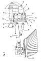
- floor cleaning machine 1 in the form of a street sweeper has a conventional basic structure with a machine frame on which the front wheels 2 and the rear wheels 3 are supported and which carries a body, which forms the driver's cab 4, inter alia.
- Structure of the drive which consists of driven brushes and cooperating with a negative pressure blower cleaning device and provided in the body dirt holding container including the various filter devices are well known as the placing of directly driven by a motor side brush 20, 21, whose location of the Operator between an inner end position, as in Fig. 1 is shown for the side brush 21, and an outer end position are adjustable, as in Fig. 1 for the side brush 20 is shown.
- a motor side brush 20 21 whose location of the Operator between an inner end position, as in Fig. 1 is shown for the side brush 21, and an outer end position are adjustable, as in Fig. 1 for the side brush 20 is shown.
- Fig. 1 for the side brush 20 is shown.
- Fig. 1 is indicated by the arrow A, the normal Vor lakeverfahrutter the floor cleaning machine 1: This arrow A is also found in the Fig. 2 . 4 . 5 and 6 to clarify the alignment of the various components.
- two support members 10, 11 extend forward beyond the body portion, which are part of a suspension for a cross member, which is displaceable by means of this suspension between a raised position and a lowered position. In each of these positions, the cross member is held substantially non-displaceable and can therefore be considered as part of the machine frame. From the cross member extends an arm-shaped portion 12 laterally outwardly, which has an approximately 45 ° angled end portion 12 '.
- Figures 2 and 4 can be pivoted to a position in which a further pivoting movement by conditioning the side edges of the coupling plates 30 ', 30 "to stops 50 (FIG. Figures 2 and 4 ) of the holding plate 44 "is prevented ( Fig. 5 ).
- connection part 24 is pivotally supported with respect to the coupling member by means of a screw pin 28 forming a pivot axis .
- This connection part 24 together with a pivotable about a horizontal axis a support arm assembly connected thereto at the forward end of the outer portion 22.
- the side brush 20, which is directly driven by a motor, is pivotally mounted at the front end of the outer portion 22.
- the support arm assembly 22, 24 is telescopically configured in a likewise conventional manner can be to allow a limited compression due to shock loads of the side brush 20, by means of a hydraulic working cylinder 26 which is articulated on the one hand on the outer portion 22 and on the other hand on the connecting part 24, between a raised displacement position and a lowered n work position are pivoted.
- a hydraulic working cylinder 32 forming an adjusting device is fastened pivotably about a pin 34.
- Its cylinder part is hinged about a pin 36 pivotally on a portion 14 of the cross member, which is held by the suspension elements containing the support elements 10, 11, i. the working cylinder 32 is articulated on the machine frame. This articulation is closer to the longitudinal center plane of the floor cleaning machine, ie further inside than the axis of rotation 40 '.
- the side brush 20 In normal cleaning operation, the side brush 20 is in a position in which it covers only a small extent or not at all the scope of the cleaning device of the floor cleaning machine, ie it is based on the median plane of the floor cleaning machine laterally pivoted outwards, so that the holding arm assembly 22nd , 24 points obliquely outward from the median plane of the floor cleaning machine. Therefore, when the side brush encounters an obstacle in this position, the holding arm assembly 22, 24 - in Fig. 1 seen from above - loaded in the direction of a counterclockwise pivoting. Since the working cylinder 32 is secured against extension under such load, the following will be described with reference to FIGS 4 to 6 described displacement movement from each intermediate operating position, ie also from a position according to Fig. 2 ,
Landscapes
- Engineering & Computer Science (AREA)
- Architecture (AREA)
- Civil Engineering (AREA)
- Structural Engineering (AREA)
- Cleaning Of Streets, Tracks, Or Beaches (AREA)
- Vehicle Cleaning, Maintenance, Repair, Refitting, And Outriggers (AREA)
- Cleaning Implements For Floors, Carpets, Furniture, Walls, And The Like (AREA)
Claims (10)
- Machine de nettoyage de sols qui se déplace sur le sol à nettoyer, comprenant un dispositif de nettoyage pour ramasser les saletés du sol ainsi qu'au moins un balai latéral (20 ; 21) qui peut être entraîné en rotation pour acheminer les saletés dans la zone de ramassage du dispositif de nettoyage, qui est supportée sur un ensemble de bras de support (22, 24), qui est monté à pivotement sur un élément de couplage (30) relié au châssis (10, 11, 12, 14) de la machine via un joint de pivotement et supporté en position de départ en fonctionnement normal et sur lequel s'engage un dispositif de réglage (32) pour positionner l'ensemble de support (22, 24) entre une position d'extrémité interne et une position d'extrémité externe par rapport au châssis (10, 11, 12, 14) de la machine, pour amener l'ensemble de support (22, 24) en position de fonctionnement, dans laquelle le balai latéral (20) se trouve dans une position latérale souhaitée par rapport à la zone d'action du dispositif de nettoyage, dans laquelle l'ensemble de support (22, 24) peut être décalé de la position de fonctionnement, lors de l'impact du balai latéral (20) sur un obstacle, par décalage de l'élément de couplage (30) de sa position de départ, dans laquelle le dispositif de réglage (32) est supporté en un point (36) fixé au châssis, qui est plus proche du plan central longitudinal de la machine de nettoyage de sols que le joint de pivotement de l'élément de couplage (30) avec le châssis (10, 11, 12, 14) de la machine, caractérisée en ce que l'ensemble de support (22, 24) pivote, au moins lors du pivotement via sa position d'extrémité externe autour de l'articulation (34) du dispositif de réglage (32) et celui-ci autour du point (36) fixé au châssis, qui le couple au châssis (10, 11, 12, 14) de la machine, si bien que l'axe pivot (28) reliant l'ensemble de support (22, 24) et l'élément de couplage (30) est décalé à l'opposé du sens du mouvement de décalage de l'extrémité de l'ensemble de support (22, 24) portant le balai latéral (20).
- Machine de nettoyage de sols selon la revendication 1, caractérisée en ce que l'ensemble de support (22, 24) peut être positionné dans une position de fonctionnement souhaitée dans la zone entre les deux positions d'extrémité.
- Machine de nettoyage de sols selon la revendication 1 ou 2, caractérisée en ce que le dispositif de réglage est un vérin (32).
- Machine de nettoyage de sols selon la revendication 3, caractérisée en ce que le vérin est un vérin hydraulique (32).
- Machine de nettoyage de sols selon l'une quelconque des revendications 1 à 5, caractérisée en ce que l'élément de couplage (30) est soumis à un pivotement depuis sa position de départ à l'encontre d'une force élastique.
- Machine de nettoyage de sols selon la revendication 5, caractérisée en ce que la force élastique est produite par un ressort (42) s'engageant dans la zone de l'axe pivot (40) reliant l'élément de couplage (30) et le châssis (10, 11, 12, 14) de la machine.
- Machine de nettoyage de sols selon la revendication 6, caractérisée en ce que le ressort se présente sous la forme d'un ressort à torsion (42).
- Machine de nettoyage de sols selon l'une quelconque des revendications 1 à 7, caractérisée en ce que l'axe pivot (28) reliant l'ensemble de support (22, 24) et l'élément de couplage (30) peut être décalé hors du point mort défini par la ligne de liaison de l'articulation (34) du dispositif de réglage (32) et de son point (36) fixé au châssis.
- Machine de nettoyage de sols selon l'une quelconque des revendications 1 à 8, caractérisée en ce que la zone de décalage de l'élément de couplage (30) est délimitée par des butées (48 ; 50) coopérant avec celui-ci.
- Machine de nettoyage de sols selon l'une quelconque des revendications 1 à 9, caractérisée en ce que l'ensemble de support (22, 24) a une forme télescopique et peut être comprimé à l'encontre d'une pression élastique.
Applications Claiming Priority (1)
| Application Number | Priority Date | Filing Date | Title |
|---|---|---|---|
| DE200510018883 DE102005018883B4 (de) | 2005-04-22 | 2005-04-22 | Bodenreinigungsmaschine |
Publications (3)
| Publication Number | Publication Date |
|---|---|
| EP1715103A2 EP1715103A2 (fr) | 2006-10-25 |
| EP1715103A3 EP1715103A3 (fr) | 2009-10-07 |
| EP1715103B1 true EP1715103B1 (fr) | 2011-02-02 |
Family
ID=36609544
Family Applications (1)
| Application Number | Title | Priority Date | Filing Date |
|---|---|---|---|
| EP20060008307 Not-in-force EP1715103B1 (fr) | 2005-04-22 | 2006-04-21 | Machine de nettoyage de sols |
Country Status (3)
| Country | Link |
|---|---|
| EP (1) | EP1715103B1 (fr) |
| DE (2) | DE102005018883B4 (fr) |
| ES (1) | ES2357966T3 (fr) |
Cited By (4)
| Publication number | Priority date | Publication date | Assignee | Title |
|---|---|---|---|---|
| EP2857586A1 (fr) | 2013-10-04 | 2015-04-08 | Hako GmbH | Machine de nettoyage du sol dotée de balai latéral |
| CN105350477A (zh) * | 2015-11-24 | 2016-02-24 | 界首市粮食机械有限责任公司 | 垃圾清扫车旋转扫把连接件 |
| CN107338751A (zh) * | 2017-07-06 | 2017-11-10 | 佛山高洁环保科技有限公司 | 一种具有输送带的扫地车 |
| CN111074822A (zh) * | 2019-12-31 | 2020-04-28 | 济南邦科清洗设备有限公司 | 一种轻重分离节能清扫系统 |
Families Citing this family (15)
| Publication number | Priority date | Publication date | Assignee | Title |
|---|---|---|---|---|
| EP1967653B1 (fr) * | 2007-03-07 | 2009-09-16 | Hako-Werke GMBH | Balayeuse |
| CN101725125B (zh) * | 2009-11-24 | 2011-06-29 | 深圳市金一泰实业有限公司 | 地面清扫车 |
| CN103952994B (zh) * | 2014-04-22 | 2016-06-01 | 牛力机械制造有限公司 | 扫地车边刷的双向防撞结构 |
| CN104563030A (zh) * | 2015-01-07 | 2015-04-29 | 芜湖爱瑞特环保科技有限公司 | 清扫保洁车边刷防撞装置 |
| WO2018096029A2 (fr) * | 2016-11-24 | 2018-05-31 | Lange Christian Sa | Balayeuse de voirie |
| BE1024757B1 (fr) * | 2016-11-24 | 2018-06-27 | Lange Christian Sa | Balayeuse de voirie |
| DE102018008269A1 (de) | 2018-04-13 | 2019-10-17 | Hako Gmbh | Straßenkehrmaschine |
| CN108755521B (zh) * | 2018-08-16 | 2024-04-26 | 吉林省北欧重型机械有限公司 | 马路护栏下地面清扫装置 |
| CN109457659B (zh) * | 2018-10-26 | 2020-05-05 | 中车山东机车车辆有限公司 | 一种适用于铁路清洁车的毛刷自动控制及监视系统 |
| CN110644401A (zh) * | 2019-09-25 | 2020-01-03 | 安徽爱瑞特新能源专用汽车股份有限公司 | 一种边刷前后双向防撞机构 |
| CN110670523A (zh) * | 2019-10-24 | 2020-01-10 | 山东浩睿智能科技有限公司 | 一种前置扫刷系统避障装置 |
| CN110904899A (zh) * | 2019-12-17 | 2020-03-24 | 吴明振 | 一种小区清扫推车的清扫装置 |
| CN111648286A (zh) * | 2020-07-01 | 2020-09-11 | 欧阳玲 | 一种便于更换边刷的扫地车边刷支架结构 |
| CN116145606A (zh) * | 2021-08-27 | 2023-05-23 | 上海高仙自动化科技发展有限公司 | 第三刷装置及具有其的地面清洁设备 |
| CN114847814B (zh) * | 2022-04-18 | 2023-12-26 | 广东美房智高机器人有限公司 | 一种清洁设备 |
Family Cites Families (5)
| Publication number | Priority date | Publication date | Assignee | Title |
|---|---|---|---|---|
| DE7210861U (de) * | 1972-03-22 | 1976-12-09 | Heidt, Guenter, 7987 Weingarten | Druckmittelbetaetigte, aus einem zylinder und einem kolben bestehende verstellvorrichtung fuer den tellerbesen von strassenreinigungsmaschinen |
| DD136989B1 (de) * | 1978-06-07 | 1982-06-30 | Sylvia Schultz | Vorrichtung zur halterung eines vorbaubesens an einer strassenkehrmaschine |
| WO1987001404A1 (fr) * | 1985-08-31 | 1987-03-12 | Morningfield Limited | Vehicules de nettoyage |
| GB2244741B (en) * | 1990-06-08 | 1995-02-15 | Schmidt Mfg & Equip | Brush mounting arm assembly for a cleaning vehicle |
| DE10106471A1 (de) * | 2001-02-13 | 2002-08-14 | Kuepper Weisser Gmbh | Kehrmaschine mit linear verlagerbarem Tellerbesen |
-
2005
- 2005-04-22 DE DE200510018883 patent/DE102005018883B4/de not_active Expired - Fee Related
-
2006
- 2006-04-21 ES ES06008307T patent/ES2357966T3/es active Active
- 2006-04-21 EP EP20060008307 patent/EP1715103B1/fr not_active Not-in-force
- 2006-04-21 DE DE200650008836 patent/DE502006008836D1/de active Active
Cited By (7)
| Publication number | Priority date | Publication date | Assignee | Title |
|---|---|---|---|---|
| EP2857586A1 (fr) | 2013-10-04 | 2015-04-08 | Hako GmbH | Machine de nettoyage du sol dotée de balai latéral |
| DE102013220147A1 (de) | 2013-10-04 | 2015-04-09 | Hako Gmbh | Bodenreinigungsmaschine mit Seitenbesen |
| DE102013220147B4 (de) * | 2013-10-04 | 2015-09-03 | Hako Gmbh | Bodenreinigungsmaschine mit Seitenbesen |
| CN105350477A (zh) * | 2015-11-24 | 2016-02-24 | 界首市粮食机械有限责任公司 | 垃圾清扫车旋转扫把连接件 |
| CN107338751A (zh) * | 2017-07-06 | 2017-11-10 | 佛山高洁环保科技有限公司 | 一种具有输送带的扫地车 |
| CN107338751B (zh) * | 2017-07-06 | 2019-03-26 | 佛山高洁环保科技有限公司 | 一种具有输送带的扫地车 |
| CN111074822A (zh) * | 2019-12-31 | 2020-04-28 | 济南邦科清洗设备有限公司 | 一种轻重分离节能清扫系统 |
Also Published As
| Publication number | Publication date |
|---|---|
| EP1715103A2 (fr) | 2006-10-25 |
| DE102005018883B4 (de) | 2010-04-01 |
| DE502006008836D1 (de) | 2011-03-17 |
| ES2357966T3 (es) | 2011-05-04 |
| DE102005018883A1 (de) | 2006-11-02 |
| EP1715103A3 (fr) | 2009-10-07 |
Similar Documents
| Publication | Publication Date | Title |
|---|---|---|
| EP1715103B1 (fr) | Machine de nettoyage de sols | |
| DE2438828C2 (de) | Stoßfänger für schwere Kraftfahrzeuge | |
| EP2408971B1 (fr) | Dispositif de brosses de balayage interchangeable et balayeuse comportant un tel dispositif de brosses de balayage | |
| EP1967653B1 (fr) | Balayeuse | |
| EP2721220A1 (fr) | Balayeuse de voirie comprenant un dispositif de réglage de disque de brosse | |
| DE2753069C2 (de) | Erntemaschine | |
| DE69908999T2 (de) | Kehrvorrichtung für Arbeitsfahrzeuge | |
| EP1714603B1 (fr) | Machine à nettoyer les sols | |
| EP2591653B2 (fr) | Machine de fenaison | |
| DE102007052401B4 (de) | Vorrichtung mit einer Kameraeinheit | |
| DE2437723C2 (de) | Straßenpflug, insbesondere zum Schneeabtragen | |
| DE202013103571U1 (de) | Boden-Reinigungsmaschine | |
| EP0482293A1 (fr) | Machine pour travailler le sol et train de roues | |
| DE10221351B4 (de) | Bodenreinigungsmaschine | |
| EP3596273B1 (fr) | Machine automotrice de nettoyage de voirie | |
| EP3274510B1 (fr) | Machine de nettoyage de sol et procédé pour faire fonctionner une machine de nettoyage de sol | |
| DE19715435A1 (de) | Überkopfwerfer-Reinigungsmaschine | |
| EP1612335B1 (fr) | Dispositif de balayage automobile | |
| EP1516965B1 (fr) | Dispositif de balayage pour une balayeuse | |
| EP1514506B1 (fr) | Machine pour nettoyer les sols | |
| DE10305611B4 (de) | Bodenreinigungsmaschine | |
| DE2853126C2 (de) | Straßenräumgerät | |
| DE102004025478B4 (de) | Landwirtschaftliche Maschine | |
| DE9116679U1 (de) | Bodenbearbeitungsvorrichtung, heb- und kippbarer Behälter sowie Fahrwerk | |
| DE202004012319U1 (de) | Einrichtung zum Bewegen des Saugmundstückes einer Kehrmaschine |
Legal Events
| Date | Code | Title | Description |
|---|---|---|---|
| PUAI | Public reference made under article 153(3) epc to a published international application that has entered the european phase |
Free format text: ORIGINAL CODE: 0009012 |
|
| AK | Designated contracting states |
Kind code of ref document: A2 Designated state(s): AT BE BG CH CY CZ DE DK EE ES FI FR GB GR HU IE IS IT LI LT LU LV MC NL PL PT RO SE SI SK TR |
|
| AX | Request for extension of the european patent |
Extension state: AL BA HR MK YU |
|
| PUAL | Search report despatched |
Free format text: ORIGINAL CODE: 0009013 |
|
| AK | Designated contracting states |
Kind code of ref document: A3 Designated state(s): AT BE BG CH CY CZ DE DK EE ES FI FR GB GR HU IE IS IT LI LT LU LV MC NL PL PT RO SE SI SK TR |
|
| AX | Request for extension of the european patent |
Extension state: AL BA HR MK YU |
|
| 17P | Request for examination filed |
Effective date: 20090918 |
|
| AKX | Designation fees paid |
Designated state(s): CH DE ES FR GB LI |
|
| GRAP | Despatch of communication of intention to grant a patent |
Free format text: ORIGINAL CODE: EPIDOSNIGR1 |
|
| GRAS | Grant fee paid |
Free format text: ORIGINAL CODE: EPIDOSNIGR3 |
|
| GRAA | (expected) grant |
Free format text: ORIGINAL CODE: 0009210 |
|
| AK | Designated contracting states |
Kind code of ref document: B1 Designated state(s): CH DE ES FR GB LI |
|
| REG | Reference to a national code |
Ref country code: GB Ref legal event code: FG4D Free format text: NOT ENGLISH |
|
| REG | Reference to a national code |
Ref country code: CH Ref legal event code: EP |
|
| REG | Reference to a national code |
Ref country code: CH Ref legal event code: NV Representative=s name: E. BLUM & CO. AG PATENT- UND MARKENANWAELTE VSP |
|
| REF | Corresponds to: |
Ref document number: 502006008836 Country of ref document: DE Date of ref document: 20110317 Kind code of ref document: P |
|
| REG | Reference to a national code |
Ref country code: DE Ref legal event code: R096 Ref document number: 502006008836 Country of ref document: DE Effective date: 20110317 |
|
| REG | Reference to a national code |
Ref country code: ES Ref legal event code: FG2A Ref document number: 2357966 Country of ref document: ES Kind code of ref document: T3 Effective date: 20110504 |
|
| PLBE | No opposition filed within time limit |
Free format text: ORIGINAL CODE: 0009261 |
|
| STAA | Information on the status of an ep patent application or granted ep patent |
Free format text: STATUS: NO OPPOSITION FILED WITHIN TIME LIMIT |
|
| 26N | No opposition filed |
Effective date: 20111103 |
|
| REG | Reference to a national code |
Ref country code: DE Ref legal event code: R097 Ref document number: 502006008836 Country of ref document: DE Effective date: 20111103 |
|
| REG | Reference to a national code |
Ref country code: FR Ref legal event code: PLFP Year of fee payment: 11 |
|
| PGFP | Annual fee paid to national office [announced via postgrant information from national office to epo] |
Ref country code: ES Payment date: 20160311 Year of fee payment: 11 |
|
| PGFP | Annual fee paid to national office [announced via postgrant information from national office to epo] |
Ref country code: CH Payment date: 20160411 Year of fee payment: 11 |
|
| REG | Reference to a national code |
Ref country code: FR Ref legal event code: PLFP Year of fee payment: 12 |
|
| REG | Reference to a national code |
Ref country code: CH Ref legal event code: PL |
|
| PG25 | Lapsed in a contracting state [announced via postgrant information from national office to epo] |
Ref country code: LI Free format text: LAPSE BECAUSE OF NON-PAYMENT OF DUE FEES Effective date: 20170430 Ref country code: CH Free format text: LAPSE BECAUSE OF NON-PAYMENT OF DUE FEES Effective date: 20170430 |
|
| REG | Reference to a national code |
Ref country code: FR Ref legal event code: PLFP Year of fee payment: 13 |
|
| REG | Reference to a national code |
Ref country code: ES Ref legal event code: FD2A Effective date: 20180703 |
|
| PG25 | Lapsed in a contracting state [announced via postgrant information from national office to epo] |
Ref country code: ES Free format text: LAPSE BECAUSE OF NON-PAYMENT OF DUE FEES Effective date: 20170422 |
|
| PGFP | Annual fee paid to national office [announced via postgrant information from national office to epo] |
Ref country code: FR Payment date: 20210309 Year of fee payment: 16 |
|
| PGFP | Annual fee paid to national office [announced via postgrant information from national office to epo] |
Ref country code: GB Payment date: 20210324 Year of fee payment: 16 |
|
| PGFP | Annual fee paid to national office [announced via postgrant information from national office to epo] |
Ref country code: DE Payment date: 20210323 Year of fee payment: 16 |
|
| REG | Reference to a national code |
Ref country code: DE Ref legal event code: R119 Ref document number: 502006008836 Country of ref document: DE |
|
| GBPC | Gb: european patent ceased through non-payment of renewal fee |
Effective date: 20220421 |
|
| PG25 | Lapsed in a contracting state [announced via postgrant information from national office to epo] |
Ref country code: GB Free format text: LAPSE BECAUSE OF NON-PAYMENT OF DUE FEES Effective date: 20220421 Ref country code: FR Free format text: LAPSE BECAUSE OF NON-PAYMENT OF DUE FEES Effective date: 20220430 Ref country code: DE Free format text: LAPSE BECAUSE OF NON-PAYMENT OF DUE FEES Effective date: 20221103 |