EP1715103B1 - Ground cleaning machine - Google Patents
Ground cleaning machine Download PDFInfo
- Publication number
- EP1715103B1 EP1715103B1 EP20060008307 EP06008307A EP1715103B1 EP 1715103 B1 EP1715103 B1 EP 1715103B1 EP 20060008307 EP20060008307 EP 20060008307 EP 06008307 A EP06008307 A EP 06008307A EP 1715103 B1 EP1715103 B1 EP 1715103B1
- Authority
- EP
- European Patent Office
- Prior art keywords
- coupling member
- cleaning machine
- floor cleaning
- holding arm
- arm arrangement
- Prior art date
- Legal status (The legal status is an assumption and is not a legal conclusion. Google has not performed a legal analysis and makes no representation as to the accuracy of the status listed.)
- Not-in-force
Links
Images


Classifications
-
- E—FIXED CONSTRUCTIONS
- E01—CONSTRUCTION OF ROADS, RAILWAYS, OR BRIDGES
- E01H—STREET CLEANING; CLEANING OF PERMANENT WAYS; CLEANING BEACHES; DISPERSING OR PREVENTING FOG IN GENERAL CLEANING STREET OR RAILWAY FURNITURE OR TUNNEL WALLS
- E01H1/00—Removing undesirable matter from roads or like surfaces, with or without moistening of the surface
- E01H1/02—Brushing apparatus, e.g. with auxiliary instruments for mechanically loosening dirt
- E01H1/05—Brushing apparatus, e.g. with auxiliary instruments for mechanically loosening dirt with driven brushes
- E01H1/053—Brushing apparatus, e.g. with auxiliary instruments for mechanically loosening dirt with driven brushes having vertical axes
Definitions
- the invention relates to a movable over the floor to be cleaned floor cleaning machine with a cleaning device for receiving dirt from the floor and with at least one rotatably driven side brush to promote dirt in the receiving area of the cleaning device, which is supported on a Gararman für, pivotally mounted on a attached via a pivotal connection with the machine frame, held in a normal position in a starting position of the coupling member and on which an actuating device for positioning the Gararman extract between an inner end position and an outer end position with respect to the machine frame engages the Gararman extract to bring in an operating position in which the side brush is in a desired lateral position with respect to the scope of the floor cleaning device, wherein the Gararman extract is displaceable upon impact of the side brush on an obstacle under displacement of the coupling member from its initial position from the operating position.
- Such floor cleaning machines are known in the form of self-propelled sweepers, in which the cleaning device comprises, for example, a suction mouth or a rotatably driven roller brush, which carry the recorded dirt with the assistance of generated by a blower vacuum in a dirt receptacle of the sweeper, the one or more side brush outside Effective range of the cleaning device, ie outside of the area in which this dirt picks up from the ground, displace dirt located inwardly toward the area of action, so that it can be absorbed by the cleaning device during the sweeping machine.
- the cleaning device comprises, for example, a suction mouth or a rotatably driven roller brush, which carry the recorded dirt with the assistance of generated by a blower vacuum in a dirt receptacle of the sweeper, the one or more side brush outside Effective range of the cleaning device, ie outside of the area in which this dirt picks up from the ground, displace dirt located inwardly toward the area of action, so that it can be absorbed by the cleaning device during the sweeping machine.
- the lateral broom which is adjustable in its lateral position relative to the cleaning mirror, encounters an obstacle, such as a raised manhole cover, a curb, a park bench or the like.
- an obstacle such as a raised manhole cover, a curb, a park bench or the like.
- some deflection of the side broom over his set operating position to allow addition.
- the holding arm arrangement of the side brush is pivotally attached to a coupling member to which also the adjusting device which acts on the Gararman extract is attached.
- the Coupling member is pivotally mounted on the machine frame and is held in its normal position by spring force in its initial position.
- the setting of the desired operating position of the side broom takes place in that by actuating the adjusting device, which consists of a hydraulic cylinder, the holding arm assembly is pivoted relative to the coupling member so that the side brush enters the desired operating position.
- the unit of side brush, arm assembly and coupling member is pivoted against spring force around the articulation point of the coupling member on the machine frame, so that the side brush following the system pressure on a circular path to the point of articulation of the coupling member on the machine frame displaced rear until a further displacement movement is prevented by a stop.
- This shifting or evasive movement of the side broom gives the operator of the floor cleaning machine a certain amount of time to stop the machine.
- the known structure fulfills the desired function, but has the disadvantage that the side brush moves immediately after hitting the obstacle on a side brushes outward, namely on a circular arc away from the longitudinal center plane of the floor cleaning machine, so that he continues in the direction shifted to the lateral obstacle. As a result, its point of attack shifts further on the side brush to its more inner area, so that an initially perhaps just possible "slipping" of the outer circumference of the side brush on the obstacle can no longer occur.
- the document GB 22 44 741 discloses a floor cleaning machine having the features of the preamble of claim 1.
- a floor cleaning machine of the type mentioned is inventively designed such that the adjusting device is mounted on a frame-fixed point, which is closer to the longitudinal center plane of the floor cleaning machine than the pivotal connection of the coupling member to the machine frame, and that the Gararman extract at least when pivoting over their outer end position also pivots about the articulation of the adjusting device and this around which they are coupled to the machine frame frame fixed point, whereby the Gararman extract and coupling member connecting pivot axis is displaced opposite to the direction of displacement movement of the side brush carrying end of the Gararman nie.
- the actuator prevents such a shift from the operating position when it has a predetermined, unchangeable length, such as if it consists of a hydraulic cylinder with hydraulically releasable check valve, which ensures that the piston rod of the working cylinder is not extended by loading beyond the set position can be.
- a predetermined, unchangeable length such as if it consists of a hydraulic cylinder with hydraulically releasable check valve, which ensures that the piston rod of the working cylinder is not extended by loading beyond the set position can be.
- a predetermined, unchangeable length such as if it consists of a hydraulic cylinder with hydraulically releasable check valve, which ensures that the piston rod of the working cylinder is not extended by loading beyond the set position can be.
- the Haltearman eleven acts as a two-armed lever and caused by the pivotal connection with the coupling member that this pivots about its pivotal connection with the machine frame, wherein the Setting device pivots about its connection point with the machine frame.
- the pivot axis connecting the holding arm assembly and the coupling member moves in the direction opposite to the displacement movement of the outer arm of a two-armed lever forming Gararman eleven and possibly.
- the connecting line of articulation of the adjusting device and the frame-fixed point dead center is about the defined by the connecting line of articulation of the adjusting device and the frame-fixed point dead center.
- the size of the displacement movement is not limited, as in the prior art, by an approach movement of the coupling member and inner part of the Gararman extract to the body portion of the floor cleaning machine, but it is a larger Verlagerungsbwegung the Sobesens possible. However, this gives the operator more time to stop the floor cleaning machine to avoid damaging the side broom suspension.
- the corresponding displacement movement of the support arm assembly and link connecting pivot axis causes the support arm assembly, in addition to the rearward movement relative to the normal travel motion of the floor cleaning machine, to also inwardly toward the longitudinal center plane of the floor cleaning machine is moved. Due to the corresponding displacement of the side broom, therefore, it can in some cases slide past an obstacle that touches it only in the outer edge area.
- the coupling member can be held by a predetermined breaking element in its initial position, which then breaks when the holding arm as a result of hitting the side broom on an obstacle is charged. However, this requires that the operator replace the destroyed breakaway member before the cleaning operation can continue.
- the coupling member is held by spring force in its initial position. This spring force can be generated by a spring acting in the region of the pivot axis connecting the coupling member and the machine frame, for example by a corresponding torsion spring arrangement. This can then also allow the evasive movement of the coupling member, which is required to move the toggle device through the dead position.
- the displacement area of the coupling member is expediently limited by stops interacting with the latter and thereby defined precisely.
- the Gararman extract can be formed telescopically and compressible against spring pressure, so that the side brush can also avoid an obstacle to some extent when the Gararman extract is aligned substantially in the direction of travel.
- floor cleaning machine 1 in the form of a street sweeper has a conventional basic structure with a machine frame on which the front wheels 2 and the rear wheels 3 are supported and which carries a body, which forms the driver's cab 4, inter alia.
- Structure of the drive which consists of driven brushes and cooperating with a negative pressure blower cleaning device and provided in the body dirt holding container including the various filter devices are well known as the placing of directly driven by a motor side brush 20, 21, whose location of the Operator between an inner end position, as in Fig. 1 is shown for the side brush 21, and an outer end position are adjustable, as in Fig. 1 for the side brush 20 is shown.
- a motor side brush 20 21 whose location of the Operator between an inner end position, as in Fig. 1 is shown for the side brush 21, and an outer end position are adjustable, as in Fig. 1 for the side brush 20 is shown.
- Fig. 1 for the side brush 20 is shown.
- Fig. 1 is indicated by the arrow A, the normal Vor lakeverfahrutter the floor cleaning machine 1: This arrow A is also found in the Fig. 2 . 4 . 5 and 6 to clarify the alignment of the various components.
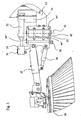
- two support members 10, 11 extend forward beyond the body portion, which are part of a suspension for a cross member, which is displaceable by means of this suspension between a raised position and a lowered position. In each of these positions, the cross member is held substantially non-displaceable and can therefore be considered as part of the machine frame. From the cross member extends an arm-shaped portion 12 laterally outwardly, which has an approximately 45 ° angled end portion 12 '.
- Figures 2 and 4 can be pivoted to a position in which a further pivoting movement by conditioning the side edges of the coupling plates 30 ', 30 "to stops 50 (FIG. Figures 2 and 4 ) of the holding plate 44 "is prevented ( Fig. 5 ).
- connection part 24 is pivotally supported with respect to the coupling member by means of a screw pin 28 forming a pivot axis .
- This connection part 24 together with a pivotable about a horizontal axis a support arm assembly connected thereto at the forward end of the outer portion 22.
- the side brush 20, which is directly driven by a motor, is pivotally mounted at the front end of the outer portion 22.
- the support arm assembly 22, 24 is telescopically configured in a likewise conventional manner can be to allow a limited compression due to shock loads of the side brush 20, by means of a hydraulic working cylinder 26 which is articulated on the one hand on the outer portion 22 and on the other hand on the connecting part 24, between a raised displacement position and a lowered n work position are pivoted.
- a hydraulic working cylinder 32 forming an adjusting device is fastened pivotably about a pin 34.
- Its cylinder part is hinged about a pin 36 pivotally on a portion 14 of the cross member, which is held by the suspension elements containing the support elements 10, 11, i. the working cylinder 32 is articulated on the machine frame. This articulation is closer to the longitudinal center plane of the floor cleaning machine, ie further inside than the axis of rotation 40 '.
- the side brush 20 In normal cleaning operation, the side brush 20 is in a position in which it covers only a small extent or not at all the scope of the cleaning device of the floor cleaning machine, ie it is based on the median plane of the floor cleaning machine laterally pivoted outwards, so that the holding arm assembly 22nd , 24 points obliquely outward from the median plane of the floor cleaning machine. Therefore, when the side brush encounters an obstacle in this position, the holding arm assembly 22, 24 - in Fig. 1 seen from above - loaded in the direction of a counterclockwise pivoting. Since the working cylinder 32 is secured against extension under such load, the following will be described with reference to FIGS 4 to 6 described displacement movement from each intermediate operating position, ie also from a position according to Fig. 2 ,
Description
Die Erfindung bezieht sich auf eine über den zu reinigenden Boden verfahrbare Bodenreinigungsmaschine mit einer Reinigungseinrichtung zur Aufnahme von Schmutz vom Boden sowie mit mindestens einem drehend antreibbaren Seitenbesen zur Förderung von Schmutz in den Aufnahmebereich der Reinigungseinrichtung, der an einer Haltearmanordnung gehaltert ist, die schwenkbar an einem über eine Schwenkverbindung mit dem Maschinenrahmen verbundenen, im normalen Betrieb in einer Ausgangsstellung gehaltenen Kopplungsglied angebracht ist und an der eine Stelleinrichtung zum Positionieren der Haltearmanordnung zwischen einer inneren Endstellung und einer äußeren End-stellung bezüglich dem Maschinenrahmen angreift, um die Haltearmanordnung in eine Betriebsstellung zu bringen, in der sich der Seitenbesen in einer gewünschten seitlichen Stellung bezüglich dem Wirkungsbereich der Bodenreinigungseinrichtung befindet, wobei die Haltearmanordnung beim Auftreffen des Seitenbesens auf ein Hindernis unter Verlagerung des Kopplungsglieds aus seiner Ausgangsstellung aus der Betriebsstellung verlagerbar ist.The invention relates to a movable over the floor to be cleaned floor cleaning machine with a cleaning device for receiving dirt from the floor and with at least one rotatably driven side brush to promote dirt in the receiving area of the cleaning device, which is supported on a Haltearmanordnung, pivotally mounted on a attached via a pivotal connection with the machine frame, held in a normal position in a starting position of the coupling member and on which an actuating device for positioning the Haltearmanordnung between an inner end position and an outer end position with respect to the machine frame engages the Haltearmanordnung to bring in an operating position in which the side brush is in a desired lateral position with respect to the scope of the floor cleaning device, wherein the Haltearmanordnung is displaceable upon impact of the side brush on an obstacle under displacement of the coupling member from its initial position from the operating position.
Derartige Bodenreinigungsmaschinen sind in Form von selbstfahrenden Kehrmaschinen bekannt, bei denen die Reinigungseinrichtung beispielsweise ein Saugmund oder eine drehend angetriebene Walzenbürste aufweist, die den aufgenommenen Schmutz mit Unterstützung von von einem Gebläse erzeugtem Unterdruck in einen Schmutzaufnahmebehälter der Kehrmaschine befördern, wobei der oder die Seitenbesen außerhalb des Wirkungsbereichs der Reinigungseinrichtung, d.h. außerhalb des Bereichs, in dem diese Schmutz vom Boden aufnimmt, befindlichen Schmutz nach innen in Richtung auf den Wirkungsbereich verlagern, so dass er beim Verfahren der Kehrmaschine von der Reinigungseinrichtung aufgenommen werden kann.Such floor cleaning machines are known in the form of self-propelled sweepers, in which the cleaning device comprises, for example, a suction mouth or a rotatably driven roller brush, which carry the recorded dirt with the assistance of generated by a blower vacuum in a dirt receptacle of the sweeper, the one or more side brush outside Effective range of the cleaning device, ie outside of the area in which this dirt picks up from the ground, displace dirt located inwardly toward the area of action, so that it can be absorbed by the cleaning device during the sweeping machine.
Im Betrieb kommt es vor, dass der in seiner seitlichen Stellung bezüglich dem Reinigungsspiegel verstellbare Seitenbesen auf ein Hindernis trifft, etwa einen erhöhten Gullideckel, einen Kantstein, eine Parkbank o.Ä. Um zu verhindern, dass bei einem derartigen Auftreffen die Halterung des Seitenbesens dauerhaft verformt wird oder bricht, und um der Bedienungsperson die Möglichkeit zu geben, die Maschine anzuhalten, bevor eine Beschädigung eintritt, ist es auch bereits bekannt, ein gewisses Ausweichen des Seitenbesens über seine eingestellte Betriebsstellung hinaus zuzulassen. Hierzu ist beispielsweise bei der Bodenreinigungsmaschine Citymaster 1800 der Anmelderin die Haltearmanordnung des Seitenbesens schwenkbar an einem Kopplungsglied befestigt, an dem auch die Stelleinrichtung, die an der Haltearmanordnung angreift, befestigt ist. Das Kopplungsglied ist schwenkbar am Maschinenrahmen gehaltert und wird im normalen Betrieb mittels Federkraft in seiner Ausgangsstellung gehalten. Die Einstellung der gewünschten Betriebsstellung des Seitenbesens erfolgt dadurch, dass durch Betätigung der Stelleinrichtung, die aus einem hydraulischen Arbeitszylinder besteht, die Haltearmanordnung gegenüber dem Kopplungsglied so verschwenkt wird, dass der Seitenbesen in die gewünschte Betriebsstellung gelangt.In operation, it can happen that the lateral broom, which is adjustable in its lateral position relative to the cleaning mirror, encounters an obstacle, such as a raised manhole cover, a curb, a park bench or the like. In order to prevent the support of the side broom from being permanently deformed or broken in such impact, and to give the operator the opportunity to stop the machine before damage occurs, it is also known that some deflection of the side broom over his set operating position to allow addition. For this purpose, for example, in the floor cleaning machine Citymaster 1800 of the applicant, the holding arm arrangement of the side brush is pivotally attached to a coupling member to which also the adjusting device which acts on the Haltearmanordnung is attached. The Coupling member is pivotally mounted on the machine frame and is held in its normal position by spring force in its initial position. The setting of the desired operating position of the side broom takes place in that by actuating the adjusting device, which consists of a hydraulic cylinder, the holding arm assembly is pivoted relative to the coupling member so that the side brush enters the desired operating position.
Wenn der Seitenbesen jedoch im Reinigungsbetrieb auf ein Hindernis trifft, wird die Einheit aus Seitenbesen, Haltearmanordnung und Kopplungsglied gegen Federkraft um den Anlenkpunkt des Kopplungsglieds am Maschinenrahmen verschwenkt, so dass sich der Seitenbesen dem Anlagedruck folgend auf einer Kreisbahn um den Anlenkpunkt des Kopplungsglieds am Maschinenrahmen nach hinten verlagert, bis eine weitere Verlagerungsbewegung durch einen Anschlag verhindert wird. Diese Verlagerungs- oder Ausweichbewegung des Seitenbesens gibt der Bedienungsperson der Bodenreinigungsmaschine eine gewisse Zeit, die Maschine anzuhalten.However, if the side brush encounters an obstacle in the cleaning operation, the unit of side brush, arm assembly and coupling member is pivoted against spring force around the articulation point of the coupling member on the machine frame, so that the side brush following the system pressure on a circular path to the point of articulation of the coupling member on the machine frame displaced rear until a further displacement movement is prevented by a stop. This shifting or evasive movement of the side broom gives the operator of the floor cleaning machine a certain amount of time to stop the machine.
Der bekannte Aufbau erfüllt die gewünschte Funktion, hat jedoch den Nachteil, dass sich der Seitenbesen unmittelbar nach Auftreffen auf das Hindernis auf einer den Seitenbesen weiter nach außen, nämlich auf einem Kreisbogen weg von der Längsmittelebene der Bodenreinigungsmaschine bewegt, so dass er sich weiter in Richtung auf das seitlich liegende Hindernis verlagert. Dadurch verlagert sich dessen Angriffspunkt am Seitenbesen weiter zu dessen mehr innen liegenden Bereich, so dass ein zunächst vielleicht gerade noch mögliches "Abgleiten" des äußeren Umfangs des Seitenbesens am Hindernis nicht mehr erfolgen kann.The known structure fulfills the desired function, but has the disadvantage that the side brush moves immediately after hitting the obstacle on a side brushes outward, namely on a circular arc away from the longitudinal center plane of the floor cleaning machine, so that he continues in the direction shifted to the lateral obstacle. As a result, its point of attack shifts further on the side brush to its more inner area, so that an initially perhaps just possible "slipping" of the outer circumference of the side brush on the obstacle can no longer occur.
Da sich die verhältnismäßig lange Einheit aus Haltearmanordnung und Kopplungsglied um den Anlenkpunkt des Kopplungsglieds am Maschinenrahmen verlagert, führen die dabei in den vorderen äußeren Randbereich der Karosserie der Bodenreinigungsmaschine gelangenden Abschnitte von Haltearmanordnung und/oder Kopplungsglied eine verhältnismäßig große Verlagerungsbewegung aus. Hierdurch gelangen sie relativ bald in den Karosseriebereich, so dass eine frühe Begrenzung der Verlagerungsbewegung durch einen Anschlag erforderlich ist.Since the relatively long unit of Haltearmanordnung and coupling member to the pivot point of the coupling member displaced on the machine frame, thereby leading into the front outer edge region of the body of the floor cleaning machine sections of the holding arm assembly and / or coupling member perform a relatively large displacement movement. As a result, they arrive relatively soon in the body area, so that an early limitation of the displacement movement is required by a stop.
Das Dokument
Es ist Aufgabe der Erfindung, eine Bodenreinigungsmaschine dahingehend zu verbessern, dass bei kompaktem Aufbau das Vorbeigleiten des Seitenbesens an einem mit ihm in Berührung kommenden Hindernis unterstützt und ein möglichst großer Verlagerungsbereich des Seitenbesens beim Auftreffen auf ein Hindernis erreicht wird.It is an object of the invention to improve a floor cleaning machine to the effect that in a compact structure, the sliding past the side broom on an obstacle coming into contact with it and the largest possible displacement of the side broom is achieved when hitting an obstacle.
Zur Lösung dieser Aufgabe wird eine Bodenreinigungsmaschine der eingangs erwähnten Art erfindungsgemäß derart ausgestaltet, dass die Stelleinrichtung an einem rahmenfesten Punkt, der näher zur Längsmittelebene der Bodenreinigungsmaschine als die Schwenkungsverbindung des Kopplungsglieds mit dem Maschinenrahmen liegt, gehaltert ist und dass die Haltearmanordnung zumindest beim Verschwenken über ihre äußere Endstellung hinaus um die Anlenkung der Stelleinrichtung und diese um den sie mit dem Maschinenrahmen koppelnden rahmenfesten Punkt schwenkt, wodurch die Haltearmanordnung und Kopplungsglied verbindende Schwenkachse entgegengesetzt zur Richtung der Verlagerungsbewegung des den Seitenbesen tragenden Endes der Haltearmanordnung verlagert wird.To solve this problem, a floor cleaning machine of the type mentioned is inventively designed such that the adjusting device is mounted on a frame-fixed point, which is closer to the longitudinal center plane of the floor cleaning machine than the pivotal connection of the coupling member to the machine frame, and that the Haltearmanordnung at least when pivoting over their outer end position also pivots about the articulation of the adjusting device and this around which they are coupled to the machine frame frame fixed point, whereby the Haltearmanordnung and coupling member connecting pivot axis is displaced opposite to the direction of displacement movement of the side brush carrying end of the Haltearmanordnung.
Während also zur Einstellung der gewünschten Betriebsstellung die den Seitenbesen halternde Haltearmanordnung, wie auch bei der vorbekannten Bodenreinigungsmaschine, gegenüber dem Kopplungsglied in die gewünschte Stellung verschwenkt wird, ist die an der Haltearmanordnung angreifende Stelleinrichtung nicht, wie bei der bekannten Bodenreinigungsmaschine, am Kopplungsglied, sondern an einem weiter innen als die Schwenkverbindung von Kopplungsglied und Maschinenrahmen liegenden, rahmenfesten Punkt gehaltert. Wenn daher der Seitenbesen auf ein Hindernis trifft, wirkt die Stelleinrichtung einer Verlagerung ihres Anlenkpunkts an der Haltearmanordnung entgegen. Hierbei verhindert die Stelleinrichtung eine solche Verlagerung aus der Betriebsstellung, wenn sie eine vorgegebene, unveränderbare Länge hat, etwa wenn sie aus einem hydraulischen Arbeitszylinder mit hydraulisch entsperrbarem Rückschlagventil besteht, das sicherstellt, dass die Kolbenstange des Arbeitszylinders nicht durch Belastung über die eingestellte Stellung hinaus ausgefahren werden kann. Wenn jedoch beispielsweise eine Stelleinrichtung in Form eines Arbeitszylinders ohne eine derartige Auszugsperre verwendet wird und dieser sich noch nicht in seiner voll gestreckten Stellung befindet, erfolgt zunächst eine Verlagerung des Angriffspunkts des Arbeitszylinders an der Haltearmanordnung, bis der Arbeitszylinder maximal gestreckt ist, die Haltearmanordnung sich also in ihrer äußeren Endstellung befindet. Bei weiterer Belastung des Seitenbesens durch den Eingriff mit dem Hindernis schwenkt nunmehr die Haltearmanordnung um den Angriffspunkt der Stelleinrichtung, d.h. die Haltearmanordnung wirkt als zweiarmiger Hebel und bewirkt durch die Schwenkverbindung mit dem Kopplungsglied, dass dieses um seine Schwenkverbindung mit dem Maschinenrahmen schwenkt, wobei auch die Stelleinrichtung um ihren Verbindungspunkt mit dem Maschinenenrahmen schwenkt. Hierbei bewegt sich die die Haltearmanordnung und das Kopplungsglied verbindende Schwenkachse in Richtung entgegengesetzt der Verlagerungsbewegung des äußeren Arms der einen zweiarmigen Hebel bildenden Haltearmanordnung und ggfs. über den durch die Verbindungslinie von Anlenkung der Stelleinrichtung und deren rahmenfesten Punkt definierten Totpunkt hinaus.Thus, while adjusting the desired operating position, the side brush holder holding arm assembly, as in the prior art floor cleaning machine, is pivoted relative to the coupling member in the desired position, the attacking on the Haltearmanordnung actuator is not, as in the known floor cleaning machine, on the coupling member, but held on a farther inside than the pivotal connection of coupling member and machine frame, frame-fixed point. Therefore, when the side brush encounters an obstacle, the actuator counteracts a displacement of its pivot point on the Haltearmanordnung. Here, the actuator prevents such a shift from the operating position when it has a predetermined, unchangeable length, such as if it consists of a hydraulic cylinder with hydraulically releasable check valve, which ensures that the piston rod of the working cylinder is not extended by loading beyond the set position can be. However, if, for example, an adjusting device in the form of a working cylinder is used without such a slide lock and this is not yet in its fully extended position, there is first a displacement of the point of application of the working cylinder on the Haltearmanordnung until the working cylinder is maximally stretched, so the Haltearmanordnung located in its outer end position. Upon further loading of the side brush by the engagement with the obstacle now pivots the Haltearmanordnung to the point of the actuator, ie the Haltearmanordnung acts as a two-armed lever and caused by the pivotal connection with the coupling member that this pivots about its pivotal connection with the machine frame, wherein the Setting device pivots about its connection point with the machine frame. In this case, the pivot axis connecting the holding arm assembly and the coupling member moves in the direction opposite to the displacement movement of the outer arm of a two-armed lever forming Haltearmanordnung and possibly. About the defined by the connecting line of articulation of the adjusting device and the frame-fixed point dead center.
Durch den erfindungsgemäßen Aufbau wird erreicht, dass sich im Falle des Auftreffens des Seitenbesens auf ein Hindernis derjenige Teil der Haltearmanordnung, der zwischen Kopplungsglied und Anlenkung der Stelleinrichtung liegt, und auch das Kopplungsglied entgegengesetzt der Annäherungsbewegung des äußeren Teils der Haltearmanordnung an die Karosserie der Bodenreinigungsmaschine bewegen. Dadurch entfernen sich Kopplungsglied und innerer Teil der Haltearmanordnung vom Karosseriebereich, während der äußere Teil der Haltearmanordnung einschließlich Seitenbesen unter Verschwenkung der Stelleinrichtung um ihren maschinenfesten Punkt um die Anlenkung der Stelleinrichtung und nicht um die Schwenkverbindung des Kopplungsglieds mit dem Maschinenenrahmen schwenkt. Auf diese Weise wird die Größe der Verlagerungsbewegung nicht, wie beim Stand der Technik, durch eine Annäherungsbewegung von Kopplungsglied und innerem Teil der Haltearmanordnung an den Karosseriebereich der Bodenreinigungsmaschine begrenzt, sondern es ist eine größere Verlagerungsbwegung des Seitenbesens möglich. Dies gibt der Bedienungsperson jedoch mehr Zeit, die Bodenreinigungsmaschine anzuhalten, um eine Beschädigung der Aufhängung des Seitenbesens zu vermeiden.By the construction according to the invention it is achieved that in case of hitting the side brush on an obstacle one Part of the Haltearmanordnung, which lies between the coupling member and articulation of the actuator, and also the coupling member opposite to the approach movement of the outer part of the Haltearmanordnung move to the body of the floor cleaning machine. As a result, the coupling member and inner part of the retaining arm assembly move away from the body portion, while the outer portion of the retaining arm assembly, including the side brush pivots about its machine fixed point about the articulation of the actuator and not about the pivotal connection of the coupling member with the machine frame pivoting the actuator. In this way, the size of the displacement movement is not limited, as in the prior art, by an approach movement of the coupling member and inner part of the Haltearmanordnung to the body portion of the floor cleaning machine, but it is a larger Verlagerungsbwegung the Seitenbesens possible. However, this gives the operator more time to stop the floor cleaning machine to avoid damaging the side broom suspension.
Insbesondere, wenn sich die Stelleinrichtung in der äußeren Endstellung der Haltearmanordnung befindet, führt die entsprechende Verlagerungsbewegung der Haltearmanordnung und Kopplungsglied verbindenden Schwenkachse dazu, dass die Haltearmanordnung zusätzlich zu der Bewegung nach hinten, bezogen auf die normale Verfahrbewegung der Bodenreinigungsmaschine, auch nach innen in Richtung auf die Längsmittelebene der Bodenreinigungsmaschine verlagert wird. Durch die entsprechende Verlagerung des Seitenbesens kann daher dieser in einzelnen Fällen an einem Hindernis vorbei gleiten, das ihn nur im äußeren Randbereich berührt.In particular, when the actuator is in the outer end position of the support arm assembly, the corresponding displacement movement of the support arm assembly and link connecting pivot axis causes the support arm assembly, in addition to the rearward movement relative to the normal travel motion of the floor cleaning machine, to also inwardly toward the longitudinal center plane of the floor cleaning machine is moved. Due to the corresponding displacement of the side broom, therefore, it can in some cases slide past an obstacle that touches it only in the outer edge area.
Das Kopplungsglied kann durch ein Sollbruchelement in seiner Ausgangsstellung gehalten werden, das dann bricht, wenn der Haltearm infolge Auftreffens des Seitenbesens auf ein Hindernis belastet wird. Dies erfordert jedoch, dass die Bedienungsperson das zerstörte Sollbruchelement ersetzt, bevor der Reinigungsbetrieb fortgesetzt werden kann. In einer bevorzugten Ausgestaltung wird daher das Kopplungsglied durch Federkraft in seiner Ausgangsstellung gehalten. Diese Federkraft kann von einer im Bereich der das Kopplungsglied und den Maschinenrahmen verbindenden Schwenkachse angreifenden Feder erzeugt werden, beispielsweise von einer entsprechenden Torsionsfederanordnung. Diese kann dann auch die Ausweichbewegung des Kopplungsglieds ermöglichen, die erforderlich ist, um die Kniehebeleinrichtung durch die Totstellung zu bewegen.The coupling member can be held by a predetermined breaking element in its initial position, which then breaks when the holding arm as a result of hitting the side broom on an obstacle is charged. However, this requires that the operator replace the destroyed breakaway member before the cleaning operation can continue. In a preferred embodiment, therefore, the coupling member is held by spring force in its initial position. This spring force can be generated by a spring acting in the region of the pivot axis connecting the coupling member and the machine frame, for example by a corresponding torsion spring arrangement. This can then also allow the evasive movement of the coupling member, which is required to move the toggle device through the dead position.
Der Verlagerungsbereich des Kopplungsglieds wird zweckmäßigerweise durch mit diesem zusammenwirkende Anschläge begrenzt und dadurch genau definiert.The displacement area of the coupling member is expediently limited by stops interacting with the latter and thereby defined precisely.
In bekannter Weise kann die Haltearmanordnung teleskopförmig ausgebildet und gegen Federdruck zusammendrückbar sein, so dass der Seitenbesen auch dann in gewissem Umfang einem Hindernis ausweichen kann, wenn die Haltearmanordnung im Wesentlichen in Fahrtrichtung ausgerichtet ist.In a known manner, the Haltearmanordnung can be formed telescopically and compressible against spring pressure, so that the side brush can also avoid an obstacle to some extent when the Haltearmanordnung is aligned substantially in the direction of travel.
Die Erfindung wird im Folgenden anhand der schematisch ein Ausführungsbeispiel zeigenden Figuren näher erläutert.
- Fig. 1
- zeigt in perspektivischer Darstellung eine Bodenreinigungsmaschine.
- Fig. 2
- zeigt in einer schematischen Teildarstellung einen Seitenbesen mit seiner Halterung in einer nach innen geschwenkten Stellung.
- Fig. 3
- zeigt in einer Teildarstellung den Aufbau der Anordnung aus
Fig. 1 in einer Seitenansicht. - Fig. 4
- zeigt in einer Darstellung entsprechend
Fig. 2 den Seitenbesen in seiner äußeren Endstellung. - Fig. 5
- zeigt in einer Darstellung entsprechend
Fig. 2 und4 den Seitenbesen in einer über die äußere Endstellung hinaus verlagerten Stellung. - Fig. 6
- zeigt in einer Darstellung entsprechend
Fig. 5 den Seitenbesen bei über den Totpunkt hinaus verlagerter Haltearmanordnung und Kopplungsglied verbindender Schwenkachse.
- Fig. 1
- shows a perspective view of a floor cleaning machine.
- Fig. 2
- shows in a schematic partial representation of a side brush with its holder in an inwardly pivoted position.
- Fig. 3
- shows in a partial view of the structure of the arrangement
Fig. 1 in a side view. - Fig. 4
- shows in a representation accordingly
Fig. 2 the side brush in its outer end position. - Fig. 5
- shows in a representation accordingly
Fig. 2 and4 the side brush in a displaced beyond the outer end position position. - Fig. 6
- shows in a representation accordingly
Fig. 5 the side brush at over the dead point of addition displaced Haltearmanordnung and coupling member connecting pivot axis.
Die in
In
Die Ausbildung und die Funktionsweisen der Halterungen der Seitenbesen 20, 21 sind gleich, und sie werden im Folgenden nur unter Bezugnahme auf die Halterung des Seitenbesens 20 erläutert.The construction and operation of the holders of the side brushes 20, 21 are the same, and will be explained below only with reference to the support of the
Vom nicht gezeigten Maschinenrahmen erstrecken sich zwei Trägerelemente 10, 11 nach vorn über den Karosseriebereich hinaus, die Teil einer Aufhängung für einen Querträger sind, der mittels dieser Aufhängung zwischen einer angehobenen Stellung und einer abgesenkten Stellung verlagerbar ist. In jeder dieser Stellungen ist der Querträger im Wesentlichen unverlagerbar gehalten und kann daher als Teil des Maschinenrahmens angesehen werden. Vom Querträger erstreckt sich ein armförmiger Abschnitt 12 seitlich nach außen, der einen etwa unter 45° abgewinkelten Endbereich 12' hat. An diesem Endbereich sind im Abstand voneinander Halteplatten 44', 44" befestigt, zwischen denen eine an sich bekannte Torsionsfederanordnung 42 aus mehreren Kautschuk- oder Kunststoffpuffern befestigt ist. Diese Torsionsfederanordnung ist mit zwei ein Kopplungsglied 30 bildenden, am oberen und unteren Ende der Torsionsfederanordnung 42 angreifenden Kopplungsplatten 30', 30" so verbunden, dass zwischen den Halteplatten 44', 44" und den Kopplungsplatten 30', 30" eine sich in etwa mittig durch die Torsionsfederanordnung 42 erstreckende, im Wesentlichen senkrechte Drehachse 40 gebildet wird, um die das Kopplungsglied 30 gegen die Kraft der Torsionsfederanordnung aus einer inneren Endstellung, in der das Kopplungsglied 30 mit Vorsprüngen 46 an an der Halteplatte 44' vorgesehenen Anschlägen 48 (
Im Abstand von der Drehachse 40 ist im äußeren Endbereich des Kopplungsglieds 30 zwischen den Kopplungsplatten 30', 30" mittels eines eine Schwenkachse bildenden Schraubenbolzens 28 ein Anschlussteil 24 bezüglich dem Kopplungsglied schwenkbar gehaltert. Dieses Anschlussteil 24 bildet zusammen mit einem um eine horizontale Achse schwenkbar mit ihm verbundenen äußeren Abschnitt 22 eine Haltearmanordnung. Am vorderem Ende des äußeren Abschnitts 22 ist in üblicher Weise der direkt von einem Motor antreibbare Seitenbesen 20 schwenkbar befestigt, der die Form eines Tellerbesens hat. Die Haltearmanordnung 22, 24, die in ebenfalls üblicher Weise teleskopartig ausgebildet sein kann, um eine begrenzte Zusammendrückung infolge Stoßbelastungen des Seitenbesens 20 zu ermöglichen, kann mittels eines hydraulischen Arbeitszylinders 26, der einerseits am äußeren Abschnitt 22 und andererseits am Anschlussteil 24 angelenkt ist, zwischen einer angehobenen Verfahrstellung und einer abgesenkten Arbeitsstellung verschwenkt werden.At a distance from the axis of
Am oberen Ende des Anschlussteils 24 ist der Kolben eines eine Stelleinrichtung bildenden hydraulischen Arbeitszylinders 32 um einen Zapfen 34 verschwenkbar befestigt. Sein Zylinderteil ist um einen Zapfen 36 schwenkbar an einem Abschnitt 14 des Querträgers angelenkt, der von der die Trägerelementen 10, 11 enthaltenden Aufhängung gehaltenen ist, d.h. der Arbeitszylinder 32 ist am Maschinenrahmen angelenkt. Diese Anlenkung liegt näher an der Längsmittelebene der Bodenreinigungmaschine, also weiter innen, als die Drehachse 40'.At the upper end of the connecting
Im normalen Betrieb der Bodenreinigungsmaschine 1 kann der Seitenbesen 20 durch Verschwenken seiner Haltearmanordnung 22, 24 mittels des Arbeitszylinders 32 um den Schraubenbolzen 28 zwischen einer inneren Endstellung, die derjenigen des Seitenbesens 21 in
Im normalen Reinigungsbetrieb befindet sich der Seitenbesen 20 in einer Stellung, in der er nur in geringem Umfang oder auch gar nicht den Wirkungsbereich der Reinigungseinrichtung der Bodenreinigungsmaschine überdeckt, d.h. er ist bezogen auf die Mittelebene der Bodenreinigungsmaschine seitlich nach außen verschwenkt, so dass die Haltearmanordnung 22, 24 von der Mittelebene der Bodenreinigungsmaschine schräg nach außen weist. Wenn daher der Seitenbesen in dieser Stellung auf ein Hindernis trifft, wird die Haltearmanordnung 22, 24 - in
In der durch volles Ausfahren des Arbeitszylinders 32 erhaltenen äußeren Endstellung des Seitenbesens 20 hat sich, wie ein Vergleich der
Bei der Verlagerung der Haltearmanordnung 22, 24 um die Anlenkung 34 des Arbeitszylinders 32 erfolgt somit, wie ein Vergleich der
Die Rückführung der Haltearmanordnung 22, 24 einschließlich Seitenbesen 20 aus der Stellung gemäß
Claims (10)
- Floor cleaning machine which can be driven over the floor to be cleaned with a cleaning device for picking up dirt from the floor and with at least one rotary driven side brush (20; 21) for conveying dirt into the pick-up section of the cleaning device, which pick-up section is secured onto a holding arm arrangement (22, 24), which is attached pivotably onto a coupling member (30) connected via a pivot connection to the machine frame (10, 11, 12, 14) and held in a starting position in normal operation, and to which holding arm arrangement an adjusting device (32) connects for positioning the holding arm arrangement (22, 24) between an inner end position and an outer end position with respect to the machine frame (10, 11, 12, 14), in order to move the holding arm arrangement (22, 24) into an operating position, in which the side brush (20) is located in a desired lateral position with respect to the effective range of the cleaning device, whereby the holding arm arrangement (22, 24) can be displaced when the side brush (20) hits an obstacle with the displacement of the coupling member (30) out of its starting position from the operating position, whereby the adjusting device (32) is secured onto a frame-anchored point (36), which is closer to the longitudinal middle plane of the floor cleaning machine than the pivot connection of the coupling member (30) with the machine frame (10, 11, 12, 14), characterised in that the holding arm arrangement (22, 24) pivots at least on pivoting beyond its outer end position about the linkage (34) of the adjusting device (32) and pivots the latter about the frame-anchored point (36) coupling it to the machine frame (10, 11, 12, 14), whereby the pivot axis (28) connecting the holding arm arrangement (22, 24) and coupling member (30) is moved opposite the direction of the displacement movement of the end of the holding arm arrangement (22, 24) supporting the side brush (20).
- Floor cleaning machine according to claim 1, characterised in that the holding arm arrangement (22, 24) can be positioned in a desired operating position in the area between the two end positions.
- Floor cleaning machine according to claim 1 or 2, characterised in that the adjusting device is a working cylinder (32).
- Floor cleaning machine according to claim 3, characterised in that the working cylinder is a hydraulic working cylinder (32).
- Floor cleaning machine according to any one of claims 1 to 5, characterised in that the coupling member (30) is pivoted against spring force out of its initial position.
- Floor cleaning machine according to claim 5, characterised in that the spring force is produced by a spring (42) engaging in the region of the pivot axis (40) connecting the coupling member (30) and the machine frame (10, 11, 12, 14).
- Floor cleaning machine according to claim 6, characterised in that the spring is formed by a torsion spring arrangement (42).
- Floor cleaning machine according to any one of claims 1 to 7, characterised in that the pivot axis (28) connecting the holding arm arrangement (22, 24) and coupling member (30) can be displaced beyond the dead centre defined by the connecting line of the linkage (34) of the adjusting device (32) and its frame-anchored point (36).
- Floor cleaning machine according to any one of claims 1 to 8, characterised in that the displacement area of the coupling member (30) is delimited by stops (48; 50) cooperating with the latter.
- Floor cleaning machine according to any one of claims 1 to 9, characterised in that the holding arm arrangement (22, 24) is designed to be telescopic and compressible against spring pressure.
Applications Claiming Priority (1)
| Application Number | Priority Date | Filing Date | Title |
|---|---|---|---|
| DE200510018883 DE102005018883B4 (en) | 2005-04-22 | 2005-04-22 | Floor cleaning machine |
Publications (3)
| Publication Number | Publication Date |
|---|---|
| EP1715103A2 EP1715103A2 (en) | 2006-10-25 |
| EP1715103A3 EP1715103A3 (en) | 2009-10-07 |
| EP1715103B1 true EP1715103B1 (en) | 2011-02-02 |
Family
ID=36609544
Family Applications (1)
| Application Number | Title | Priority Date | Filing Date |
|---|---|---|---|
| EP20060008307 Not-in-force EP1715103B1 (en) | 2005-04-22 | 2006-04-21 | Ground cleaning machine |
Country Status (3)
| Country | Link |
|---|---|
| EP (1) | EP1715103B1 (en) |
| DE (2) | DE102005018883B4 (en) |
| ES (1) | ES2357966T3 (en) |
Cited By (4)
| Publication number | Priority date | Publication date | Assignee | Title |
|---|---|---|---|---|
| EP2857586A1 (en) | 2013-10-04 | 2015-04-08 | Hako GmbH | Floor cleaning machine with side brush |
| CN105350477A (en) * | 2015-11-24 | 2016-02-24 | 界首市粮食机械有限责任公司 | Rotation besom connecting piece of rubbish sweeping vehicle |
| CN107338751A (en) * | 2017-07-06 | 2017-11-10 | 佛山高洁环保科技有限公司 | A kind of road sweeper with conveyer belt |
| CN111074822A (en) * | 2019-12-31 | 2020-04-28 | 济南邦科清洗设备有限公司 | Light-heavy separation energy-saving cleaning system |
Families Citing this family (14)
| Publication number | Priority date | Publication date | Assignee | Title |
|---|---|---|---|---|
| DE502007001538D1 (en) * | 2007-03-07 | 2009-10-29 | Hako Gmbh | sweeper |
| CN101725125B (en) * | 2009-11-24 | 2011-06-29 | 深圳市金一泰实业有限公司 | Ground sweeper |
| CN103952994B (en) * | 2014-04-22 | 2016-06-01 | 牛力机械制造有限公司 | The way anti-collision structure of road sweeper limit brush |
| CN104563030A (en) * | 2015-01-07 | 2015-04-29 | 芜湖爱瑞特环保科技有限公司 | Anti-collision device for side brush of cleaning vehicle |
| BE1024757B1 (en) | 2016-11-24 | 2018-06-27 | Lange Christian Sa | ROAD SWEEPER |
| WO2018096029A2 (en) * | 2016-11-24 | 2018-05-31 | Lange Christian Sa | Street sweeper |
| DE102018008269A1 (en) | 2018-04-13 | 2019-10-17 | Hako Gmbh | street sweeper |
| CN108755521A (en) * | 2018-08-16 | 2018-11-06 | 吉林省北欧重型机械有限公司 | Ground swe eper under road guardrail |
| CN109457659B (en) * | 2018-10-26 | 2020-05-05 | 中车山东机车车辆有限公司 | Brush automatic control and monitoring system suitable for railway cleaning vehicle |
| CN110670523A (en) * | 2019-10-24 | 2020-01-10 | 山东浩睿智能科技有限公司 | Obstacle avoidance device of front-mounted sweeping system |
| CN110904899A (en) * | 2019-12-17 | 2020-03-24 | 吴明振 | Cleaning device of district cleaning cart |
| CN111648286A (en) * | 2020-07-01 | 2020-09-11 | 欧阳玲 | Sweeper limit brush supporting structure convenient to change limit brush |
| CN113652993B (en) * | 2021-08-27 | 2023-04-11 | 上海高仙自动化科技发展有限公司 | Third brush device and floor cleaning equipment with same |
| CN114847814B (en) * | 2022-04-18 | 2023-12-26 | 广东美房智高机器人有限公司 | Cleaning equipment |
Family Cites Families (5)
| Publication number | Priority date | Publication date | Assignee | Title |
|---|---|---|---|---|
| DE7210861U (en) * | 1972-03-22 | 1976-12-09 | Heidt, Guenter, 7987 Weingarten | PRESSURE-ACTUATED ADJUSTMENT DEVICE FOR THE DISC BRUSH OF STREET CLEANING MACHINES, COMPOSING A CYLINDER AND A PISTON |
| DD136989B1 (en) * | 1978-06-07 | 1982-06-30 | Sylvia Schultz | DEVICE FOR MOUNTING A BUILDING SUITE ON A ROAD TRAFFIC MACHINE |
| AU591519B2 (en) * | 1985-08-31 | 1989-12-07 | Morningfield Limited | Cleaning vehicle |
| GB2244741B (en) * | 1990-06-08 | 1995-02-15 | Schmidt Mfg & Equip | Brush mounting arm assembly for a cleaning vehicle |
| DE10106471A1 (en) * | 2001-02-13 | 2002-08-14 | Kuepper Weisser Gmbh | Sweeping machine with rotary plate brush reciprocated via linear guide device relative to suction opening |
-
2005
- 2005-04-22 DE DE200510018883 patent/DE102005018883B4/en not_active Expired - Fee Related
-
2006
- 2006-04-21 EP EP20060008307 patent/EP1715103B1/en not_active Not-in-force
- 2006-04-21 ES ES06008307T patent/ES2357966T3/en active Active
- 2006-04-21 DE DE200650008836 patent/DE502006008836D1/en active Active
Cited By (7)
| Publication number | Priority date | Publication date | Assignee | Title |
|---|---|---|---|---|
| EP2857586A1 (en) | 2013-10-04 | 2015-04-08 | Hako GmbH | Floor cleaning machine with side brush |
| DE102013220147A1 (en) | 2013-10-04 | 2015-04-09 | Hako Gmbh | Floor cleaning machine with side brush |
| DE102013220147B4 (en) * | 2013-10-04 | 2015-09-03 | Hako Gmbh | Floor cleaning machine with side brush |
| CN105350477A (en) * | 2015-11-24 | 2016-02-24 | 界首市粮食机械有限责任公司 | Rotation besom connecting piece of rubbish sweeping vehicle |
| CN107338751A (en) * | 2017-07-06 | 2017-11-10 | 佛山高洁环保科技有限公司 | A kind of road sweeper with conveyer belt |
| CN107338751B (en) * | 2017-07-06 | 2019-03-26 | 佛山高洁环保科技有限公司 | A kind of road sweeper with conveyer belt |
| CN111074822A (en) * | 2019-12-31 | 2020-04-28 | 济南邦科清洗设备有限公司 | Light-heavy separation energy-saving cleaning system |
Also Published As
| Publication number | Publication date |
|---|---|
| EP1715103A3 (en) | 2009-10-07 |
| ES2357966T3 (en) | 2011-05-04 |
| EP1715103A2 (en) | 2006-10-25 |
| DE102005018883B4 (en) | 2010-04-01 |
| DE502006008836D1 (en) | 2011-03-17 |
| DE102005018883A1 (en) | 2006-11-02 |
Similar Documents
| Publication | Publication Date | Title |
|---|---|---|
| EP1715103B1 (en) | Ground cleaning machine | |
| EP1967653B1 (en) | Road sweeper | |
| DE2753069C2 (en) | Harvester | |
| DE102009014560A1 (en) | Replaceable sweeping brush and sweeper with such sweeping brush device | |
| WO2012171579A1 (en) | Sweeping vehicle having a brush disk adjuster | |
| DE69908999T2 (en) | Sweeper for work vehicles | |
| EP1714603B1 (en) | Floor cleaning machine | |
| DE102007059943A1 (en) | wheelchair lift | |
| EP2591653B2 (en) | Haymaking machine | |
| DE102007052401B4 (en) | Device with a camera unit | |
| DE2437723C2 (en) | Street plow, especially for removing snow | |
| EP1266551A2 (en) | Working machine for mounting on a vehicle | |
| EP0482293A1 (en) | Groundworking machine and undercarriage | |
| EP3596273B1 (en) | Self-propelled street cleaning machine | |
| DE10149364A1 (en) | mower | |
| EP3274510B1 (en) | Ground-cleaning machine and method for operating a ground-cleaning machine | |
| DE19715435A1 (en) | Street cleaning machine with brushes | |
| DE10221351B4 (en) | Floor cleaning machine | |
| EP1612335B1 (en) | Automotive sweeping apparatus | |
| EP1516965B1 (en) | Sweeping device for a sweeping apparatus | |
| DE10221352B4 (en) | Floor cleaning machine | |
| DE2558029A1 (en) | STREET CLEANING VEHICLE | |
| EP1514506B1 (en) | Floor cleaning machine | |
| DE10305611B4 (en) | Floor cleaning machine | |
| DE2853126C2 (en) | Road clearing device |
Legal Events
| Date | Code | Title | Description |
|---|---|---|---|
| PUAI | Public reference made under article 153(3) epc to a published international application that has entered the european phase |
Free format text: ORIGINAL CODE: 0009012 |
|
| AK | Designated contracting states |
Kind code of ref document: A2 Designated state(s): AT BE BG CH CY CZ DE DK EE ES FI FR GB GR HU IE IS IT LI LT LU LV MC NL PL PT RO SE SI SK TR |
|
| AX | Request for extension of the european patent |
Extension state: AL BA HR MK YU |
|
| PUAL | Search report despatched |
Free format text: ORIGINAL CODE: 0009013 |
|
| AK | Designated contracting states |
Kind code of ref document: A3 Designated state(s): AT BE BG CH CY CZ DE DK EE ES FI FR GB GR HU IE IS IT LI LT LU LV MC NL PL PT RO SE SI SK TR |
|
| AX | Request for extension of the european patent |
Extension state: AL BA HR MK YU |
|
| 17P | Request for examination filed |
Effective date: 20090918 |
|
| AKX | Designation fees paid |
Designated state(s): CH DE ES FR GB LI |
|
| GRAP | Despatch of communication of intention to grant a patent |
Free format text: ORIGINAL CODE: EPIDOSNIGR1 |
|
| GRAS | Grant fee paid |
Free format text: ORIGINAL CODE: EPIDOSNIGR3 |
|
| GRAA | (expected) grant |
Free format text: ORIGINAL CODE: 0009210 |
|
| AK | Designated contracting states |
Kind code of ref document: B1 Designated state(s): CH DE ES FR GB LI |
|
| REG | Reference to a national code |
Ref country code: GB Ref legal event code: FG4D Free format text: NOT ENGLISH |
|
| REG | Reference to a national code |
Ref country code: CH Ref legal event code: EP |
|
| REG | Reference to a national code |
Ref country code: CH Ref legal event code: NV Representative=s name: E. BLUM & CO. AG PATENT- UND MARKENANWAELTE VSP |
|
| REF | Corresponds to: |
Ref document number: 502006008836 Country of ref document: DE Date of ref document: 20110317 Kind code of ref document: P |
|
| REG | Reference to a national code |
Ref country code: DE Ref legal event code: R096 Ref document number: 502006008836 Country of ref document: DE Effective date: 20110317 |
|
| REG | Reference to a national code |
Ref country code: ES Ref legal event code: FG2A Ref document number: 2357966 Country of ref document: ES Kind code of ref document: T3 Effective date: 20110504 |
|
| PLBE | No opposition filed within time limit |
Free format text: ORIGINAL CODE: 0009261 |
|
| STAA | Information on the status of an ep patent application or granted ep patent |
Free format text: STATUS: NO OPPOSITION FILED WITHIN TIME LIMIT |
|
| 26N | No opposition filed |
Effective date: 20111103 |
|
| REG | Reference to a national code |
Ref country code: DE Ref legal event code: R097 Ref document number: 502006008836 Country of ref document: DE Effective date: 20111103 |
|
| REG | Reference to a national code |
Ref country code: FR Ref legal event code: PLFP Year of fee payment: 11 |
|
| PGFP | Annual fee paid to national office [announced via postgrant information from national office to epo] |
Ref country code: ES Payment date: 20160311 Year of fee payment: 11 |
|
| PGFP | Annual fee paid to national office [announced via postgrant information from national office to epo] |
Ref country code: CH Payment date: 20160411 Year of fee payment: 11 |
|
| REG | Reference to a national code |
Ref country code: FR Ref legal event code: PLFP Year of fee payment: 12 |
|
| REG | Reference to a national code |
Ref country code: CH Ref legal event code: PL |
|
| PG25 | Lapsed in a contracting state [announced via postgrant information from national office to epo] |
Ref country code: LI Free format text: LAPSE BECAUSE OF NON-PAYMENT OF DUE FEES Effective date: 20170430 Ref country code: CH Free format text: LAPSE BECAUSE OF NON-PAYMENT OF DUE FEES Effective date: 20170430 |
|
| REG | Reference to a national code |
Ref country code: FR Ref legal event code: PLFP Year of fee payment: 13 |
|
| REG | Reference to a national code |
Ref country code: ES Ref legal event code: FD2A Effective date: 20180703 |
|
| PG25 | Lapsed in a contracting state [announced via postgrant information from national office to epo] |
Ref country code: ES Free format text: LAPSE BECAUSE OF NON-PAYMENT OF DUE FEES Effective date: 20170422 |
|
| PGFP | Annual fee paid to national office [announced via postgrant information from national office to epo] |
Ref country code: FR Payment date: 20210309 Year of fee payment: 16 |
|
| PGFP | Annual fee paid to national office [announced via postgrant information from national office to epo] |
Ref country code: GB Payment date: 20210324 Year of fee payment: 16 |
|
| PGFP | Annual fee paid to national office [announced via postgrant information from national office to epo] |
Ref country code: DE Payment date: 20210323 Year of fee payment: 16 |
|
| REG | Reference to a national code |
Ref country code: DE Ref legal event code: R119 Ref document number: 502006008836 Country of ref document: DE |
|
| GBPC | Gb: european patent ceased through non-payment of renewal fee |
Effective date: 20220421 |
|
| PG25 | Lapsed in a contracting state [announced via postgrant information from national office to epo] |
Ref country code: GB Free format text: LAPSE BECAUSE OF NON-PAYMENT OF DUE FEES Effective date: 20220421 Ref country code: FR Free format text: LAPSE BECAUSE OF NON-PAYMENT OF DUE FEES Effective date: 20220430 Ref country code: DE Free format text: LAPSE BECAUSE OF NON-PAYMENT OF DUE FEES Effective date: 20221103 |