EP1684502B1 - Image pickup apparatus and image pickup method therefor as well as image pickup program implementing the method and storage medium storing the program - Google Patents
Image pickup apparatus and image pickup method therefor as well as image pickup program implementing the method and storage medium storing the program Download PDFInfo
- Publication number
- EP1684502B1 EP1684502B1 EP06250347A EP06250347A EP1684502B1 EP 1684502 B1 EP1684502 B1 EP 1684502B1 EP 06250347 A EP06250347 A EP 06250347A EP 06250347 A EP06250347 A EP 06250347A EP 1684502 B1 EP1684502 B1 EP 1684502B1
- Authority
- EP
- European Patent Office
- Prior art keywords
- image pickup
- pickup apparatus
- shake
- panning
- correction
- Prior art date
- Legal status (The legal status is an assumption and is not a legal conclusion. Google has not performed a legal analysis and makes no representation as to the accuracy of the status listed.)
- Not-in-force
Links
- 238000000034 method Methods 0.000 title claims description 30
- 238000004091 panning Methods 0.000 claims description 123
- 230000000694 effects Effects 0.000 claims description 14
- 230000007704 transition Effects 0.000 description 24
- 238000010586 diagram Methods 0.000 description 11
- 230000002265 prevention Effects 0.000 description 10
- 230000006870 function Effects 0.000 description 9
- 230000008569 process Effects 0.000 description 8
- 230000003287 optical effect Effects 0.000 description 7
- 230000001419 dependent effect Effects 0.000 description 3
- 230000015556 catabolic process Effects 0.000 description 2
- 230000008859 change Effects 0.000 description 2
- 238000006731 degradation reaction Methods 0.000 description 2
- 230000010354 integration Effects 0.000 description 2
- 238000004891 communication Methods 0.000 description 1
- 230000000994 depressogenic effect Effects 0.000 description 1
- 238000009432 framing Methods 0.000 description 1
- 230000000630 rising effect Effects 0.000 description 1
- 238000005070 sampling Methods 0.000 description 1
Images


Classifications
-
- H—ELECTRICITY
- H04—ELECTRIC COMMUNICATION TECHNIQUE
- H04N—PICTORIAL COMMUNICATION, e.g. TELEVISION
- H04N23/00—Cameras or camera modules comprising electronic image sensors; Control thereof
- H04N23/60—Control of cameras or camera modules
- H04N23/68—Control of cameras or camera modules for stable pick-up of the scene, e.g. compensating for camera body vibrations
-
- G—PHYSICS
- G02—OPTICS
- G02B—OPTICAL ELEMENTS, SYSTEMS OR APPARATUS
- G02B27/00—Optical systems or apparatus not provided for by any of the groups G02B1/00 - G02B26/00, G02B30/00
- G02B27/0025—Optical systems or apparatus not provided for by any of the groups G02B1/00 - G02B26/00, G02B30/00 for optical correction, e.g. distorsion, aberration
- G02B27/0068—Optical systems or apparatus not provided for by any of the groups G02B1/00 - G02B26/00, G02B30/00 for optical correction, e.g. distorsion, aberration having means for controlling the degree of correction, e.g. using phase modulators, movable elements
-
- G—PHYSICS
- G02—OPTICS
- G02B—OPTICAL ELEMENTS, SYSTEMS OR APPARATUS
- G02B27/00—Optical systems or apparatus not provided for by any of the groups G02B1/00 - G02B26/00, G02B30/00
- G02B27/64—Imaging systems using optical elements for stabilisation of the lateral and angular position of the image
- G02B27/646—Imaging systems using optical elements for stabilisation of the lateral and angular position of the image compensating for small deviations, e.g. due to vibration or shake
-
- G—PHYSICS
- G03—PHOTOGRAPHY; CINEMATOGRAPHY; ANALOGOUS TECHNIQUES USING WAVES OTHER THAN OPTICAL WAVES; ELECTROGRAPHY; HOLOGRAPHY
- G03B—APPARATUS OR ARRANGEMENTS FOR TAKING PHOTOGRAPHS OR FOR PROJECTING OR VIEWING THEM; APPARATUS OR ARRANGEMENTS EMPLOYING ANALOGOUS TECHNIQUES USING WAVES OTHER THAN OPTICAL WAVES; ACCESSORIES THEREFOR
- G03B17/00—Details of cameras or camera bodies; Accessories therefor
-
- H—ELECTRICITY
- H04—ELECTRIC COMMUNICATION TECHNIQUE
- H04N—PICTORIAL COMMUNICATION, e.g. TELEVISION
- H04N23/00—Cameras or camera modules comprising electronic image sensors; Control thereof
- H04N23/60—Control of cameras or camera modules
- H04N23/68—Control of cameras or camera modules for stable pick-up of the scene, e.g. compensating for camera body vibrations
- H04N23/681—Motion detection
- H04N23/6815—Motion detection by distinguishing pan or tilt from motion
-
- H—ELECTRICITY
- H04—ELECTRIC COMMUNICATION TECHNIQUE
- H04N—PICTORIAL COMMUNICATION, e.g. TELEVISION
- H04N23/00—Cameras or camera modules comprising electronic image sensors; Control thereof
- H04N23/60—Control of cameras or camera modules
- H04N23/68—Control of cameras or camera modules for stable pick-up of the scene, e.g. compensating for camera body vibrations
- H04N23/682—Vibration or motion blur correction
- H04N23/685—Vibration or motion blur correction performed by mechanical compensation
- H04N23/687—Vibration or motion blur correction performed by mechanical compensation by shifting the lens or sensor position
-
- G—PHYSICS
- G03—PHOTOGRAPHY; CINEMATOGRAPHY; ANALOGOUS TECHNIQUES USING WAVES OTHER THAN OPTICAL WAVES; ELECTROGRAPHY; HOLOGRAPHY
- G03B—APPARATUS OR ARRANGEMENTS FOR TAKING PHOTOGRAPHS OR FOR PROJECTING OR VIEWING THEM; APPARATUS OR ARRANGEMENTS EMPLOYING ANALOGOUS TECHNIQUES USING WAVES OTHER THAN OPTICAL WAVES; ACCESSORIES THEREFOR
- G03B2217/00—Details of cameras or camera bodies; Accessories therefor
- G03B2217/005—Blur detection
Definitions
- the present invention relates to an image pickup apparatus and an image pickup method therefor as well as an image pickup program implementing the method and a storage medium storing the program, and more particularly to an image pickup apparatus equipped with a shake correction function and an image pickup method therefor as well as an image pickup program implementing the method and a storage medium storing the program.
- Some image pickup apparatuses such as cameras or video cameras, incorporate an optical shake correction device so as to exert a shake correction function.
- Shake correction by this shake correction device is performed by driving a shift lens as a part of taking lenses in a direction perpendicular to the optical axis of the taking lenses to thereby change the optical axis of the taking lenses.
- FIG. 8 is a block diagram schematically showing the arrangement of an image pickup apparatus incorporating the conventional shake correction device.
- the correction of a shake of an image pickup apparatus is performed in two directions, i.e. a horizontal direction and a vertical direction, on a plane perpendicular to the optical axis of the taking lenses of the image pickup apparatus.
- a horizontal direction i.e. a horizontal direction
- a vertical direction i.e. a plane perpendicular to the optical axis of the taking lenses of the image pickup apparatus.
- FIG. 8 the image pickup apparatus configured to perform shake correction only in the horizontal direction.
- the image pickup apparatus 800 is comprised of an angular velocity sensor 101' that outputs an angular velocity signal representative of a shake of the image pickup apparatus 800, a high-pass filter (HPF) 102' that eliminates a drift and other undesired components of the angular velocity signal output from the angular velocity sensor 101', an amplifier 103' that amplifies the angular velocity signal output from the angular velocity sensor 101', a camera system control microcomputer (hereinafter simply referred to as "the microcomputer") 120' that controls camera functions including shake correction, autofocus (AF), zoom, and automatic exposure (AE), a shift lens 133' as a part of taking lenses, not shown, a position sensor 115' that detects the position of the shift lens 133' to output a position signal, an amplifier 116' that amplifies the position signal output from the position sensor 115', and an H bridge driver 114' that drives the shift lens 133' horizontally on a plane perpendicular to the optical
- the microcomputer 120' is comprised of a built-in A/D converter 104' that converts the angular velocity signal into a digital signal to provide angular velocity data, an HPF 105' and a phase compensation filter 106' that perform predetermined signal processing on the angular velocity data, a variable HPF 107' that is capable of changing a cut-off frequency for panning control, described in detail hereinafter, an integrator 108' that generates an angular signal to provide a correction signal as a target drive value for driving the shift lens 133', a built-in A/D converter 117' that converts the position signal amplified by the amplifier 116' into a digital signal to provide position data, an adder 111' that calculates the difference between the current position of the shift lens 133' and the target drive value to output an actual correction amount, a low-pass filter (LPF) 112' that filters the output from the adder 111' to reduce drive noise generated by the H bridge driver 114', and a pulse width modulator
- the microcomputer 120' drives the shift lens 133' on a plane perpendicular to the lens optical axis by the H bridge driver 114' in accordance with the PWMed output from the PWM section 113', to thereby perform shake correction.
- the panning control includes, by way of example, changing the cut-off frequency of the variable HPF 107' when the output from the integrator 108' exceeds a predetermined correction range, so as to eliminate low-frequency signal components of the integrator output to thereby limit the amount of shake correction.
- this panning control makes the shake correction signal, indicative of a target position, closer to a central position of the image pickup area, thereby eliminating the above-mentioned inconvenience.
- FIG. 9 is a diagram showing changes in the HPF cut-off frequency (Hz) dependent on changes in the magnitude of the output from the integrator in FIG. 8 .
- a line graph shows the relationship between the magnitude of the output from the integrator 108' and the HPF cut-off frequency (Hz).
- the HPF cut-off frequency (Hz) of the variable HPF 107' becomes higher with an increase in the output from the integrator 108'.
- the HPF cut-off frequency (Hz) rises more sharply so as to prevent occurrence of the correction end-hitting phenomenon.
- the amount of shake correction is limited during the panning operation by changing the HPF cut-off frequency (Hz) of the variable HPF 107' according to the magnitude of the output from the integrator 108', as described above, whereby an image can be moved as intended by the photographer.
- Hz HPF cut-off frequency
- the shake prevention effect is higher so as to pick up an unblurred image.
- panning control is sometimes executed, which can cause degradation of the shake prevention effect.
- a method has been proposed in which the panning control is switched between moving image shooting and still image shooting (see e.g. Japanese Laid-Open Patent Publication (Kokai) No. 2002-209136).
- another method has been proposed in which the panning control is inhibited during still image shooting (see e.g. Japanese Laid-Open Patent Publication (Kokai) No. 2002-359768 ).
- US2002/0027599 A1 discloses a camera which adapts the blur correction to the detected amount of shake and to the shutter speed, such that when the shutter speed is set slower, the limitation of the correction amount is set larger.
- the present invention is intended to provide an image pickup apparatus and an image pickup method therefor which are capable of changing panning control according to the shutter speed to thereby provide a shake prevention effect suitable for shooting conditions, as well as an image pickup program implementing the method and a storage medium storing the program.
- the panning control characteristic when the image pickup apparatus is in a panning condition is changed according to the shutter speed. Therefore, it is possible to change the panning control according to the shutter speed to thereby provide a shake prevention effect suitable for shooting conditions.
- FIG. 1 is a block diagram schematically showing the arrangement of an image pickup apparatus according to an embodiment of the present invention.
- the image pickup apparatus 100 is comprised of a lens unit 130, a CCD 135 that photoelectrically converts an object image formed by the lens unit 130, an analog signal processing section 136 that is comprises of a CDS (Co-related Double Sampling) circuit and an AGC (Automatic Gain Control) circuit and performs predetermined processing on a signal obtained by the CCD 135 to generate an analog image pickup signal, and a camera signal processing circuit 137 that incorporates an A/D converter and performs digital signal processing to generate a final output video signal. These components are connected in series.
- the lens unit 130 is comprised of a fixed lens group 131, a zoom lens group 132, a shift lens group 133, and a focus compensation lens group 134.
- the image pickup apparatus 100 is provided with an angular velocity sensor 101 that detects an angular velocity, i.e. a shake of the image pickup apparatus to output an angular velocity signal, a high-pass filter (HPF) 102 that eliminates a drift and other undesired components of the angular velocity signal output from the angular velocity sensor 101, an amplifier 103 that amplifies the angular velocity signal high-pass filtered by the HPF 102, a camera system control microcomputer (hereinafter simply referred to as "the microcomputer") 120 that controls camera functions including shake correction, autofocus (AF), zoom, and automatic exposure (AE). These components are connected in series.
- an angular velocity sensor 101 that detects an angular velocity, i.e. a shake of the image pickup apparatus to output an angular velocity signal
- HPF high-pass filter
- the microcomputer 120 that controls camera functions including shake correction, autofocus (AF), zoom, and automatic exposure (AE).
- the image pickup apparatus 100 is provided with an H bridge driver 114 connected to the shift lens group 133, and a pulse width modulator (PWM) section 113, referred to hereinafter; a CCD drive circuit 138 connected to the CCD 135, and a shutter control section 121, described hereinafter, to drivingly control the CCD 135; a position sensor 115 that detects the position of the shift lens group 133; and an amplifier 116 connected to the position sensor 115, and an A/D converter 117, referred to hereinafter.
- PWM pulse width modulator
- the microcomputer 120 is comprised of an A/D converter 104 that converts the angular velocity signal into a digital signal to provide angular velocity data, a high-pass filter (HPF) 105 and a phase compensation filter 106 that perform predetermined signal processing on the angular velocity data, a variable high-pass filter (HPF) 107 that is capable of changing a cut-off frequency for panning control, and an integrator 108 that generates an angular signal to output a correction signal as a target drive value for driving the shift lens group 133. These components are connected in series.
- the microcomputer 120 includes the A/D converter 117 that converts the output amplified by the amplifier 116 into a digital signal to provide position data, an adder 111 that calculates the difference between the current position of the shift lens group 133 and the target drive value to output an actual correction amount, a low-pass filter (LPF) 112 that reduces drive noise generated during driving of the shift lens group 133 by the H bridge driver 114, and the PWM section 113 that performs pulse width modulation (PWM) on the output from the LPF 112.
- LPF low-pass filter
- PWM pulse width modulation
- the microcomputer 120 includes a panning control section 122 that is connected to the variable HPF 107 and the integrator 108 and performs panning control by setting a panning transition threshold according to shutter speed and by changing the cut-off frequency of the variable HPF 107 based on the correction signal output from the integrator 108, and a shutter control section 121 that is connected to the panning control section 122 and the CCD drive circuit 138 and sets optimum shutter speed based on the output video signal output from the camera signal processing circuit 137 to thereby control the CCD drive circuit 138 and transmit information on the current shutter speed to the panning control section 122.
- a panning control section 122 that is connected to the variable HPF 107 and the integrator 108 and performs panning control by setting a panning transition threshold according to shutter speed and by changing the cut-off frequency of the variable HPF 107 based on the correction signal output from the integrator 108
- a shutter control section 121 that is connected to the panning control section 122 and the CCD drive circuit 138 and
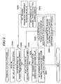
- FIG. 2 is a flowchart showing a panning control process which is executed by the image pickup apparatus in FIG. 1 .
- a set value of the shutter speed is read in (step S201), and then it is determined whether the shutter speed is not lower than a first predetermined speed (step S202).
- the first predetermined speed is set, basically based on a lens focal length, to a value at and above which the shake correction is unnecessary. For example, if the lens focal length corresponds to 250 mm on a 135 film camera, the first predetermined speed is set to a shutter speed of 1/250 sec.
- the panning transition threshold is set to a minimum value (step S203), and the image pick-up device 100 is set to a normal panning control characteristic (step S204).
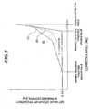
- the normal panning control characteristic is represented by a line graph (1) in FIG. 3 , which shows that the cut-off frequency of the variable HPF 107 starts rising at a time point the correction angle exceeds the minimum value of the panning transition threshold, and further, when the correction angle has increased to some extent, the slope of the line graph (1) is made sharper, to thereby prevent occurrence of the correction end-hitting phenomenon.
- the ordinate represents the set value of the HPF cut-off frequency in the panning control operation
- the abscissa represents the shake correction angle (shake correction amount) calculated by using the correction signal output from the integrator 108 and taking into account the focal length of the lens unit 130, etc.
- the shutter speed is below the first predetermined speed, i.e. if the shutter speed is slower than the first predetermined speed, it is determined whether or not the shutter speed is not higher than a second predetermined speed (step S205).
- the second predetermined speed is set to a lower shutter speed value e.g. 1/8 sec at and below which shake correction is estimated to be undoubtedly required.
- the panning transition threshold is set to a maximum value (step S206), and the image pickup apparatus 100 is set to a panning control characteristic for low-shutter speed (step S207).
- the panning control characteristic of the image pickup apparatus 100 is set to one represented by a line graph (2) in FIG. 3 . More specifically, the panning transition threshold is set to be close to a maximum correction angle (correction end), which enables correction of a large blur.
- the cut-off frequency of the variable HPF 107 is highly increased to suppress an inappropriate operation due to correction end hitting as much as possible.
- the panning control characteristic is set to one for low-shutter speed, the inappropriate operation due to the correction end hitting is suppressed by the integration effect of images stored in the CCD 135 over a long time period (e.g. 1/8 sec.).
- an interpolated panning transition threshold is calculated from the maximum value of the panning transition threshold and the minimum value of the same according to the shutter speed (step S208), and the panning control characteristic is set so as to be suited to the shutter speed (step S209).
- the panning control characteristic set according to the shutter speed is represented by a line graph (3) as an intermediate characteristic between ones represented by the line graphs (1) and (2).
- the shutter speed read in the step S201 corresponds to the length of a time period over which an image is stored in the CCD 135.
- data associated with respective values of the shutter speed are provided as shown in FIG. 4 so as to facilitate computation of the panning transition threshold and enable high-speed computation of the panning transition threshold.
- transition to panning control is made more ready to occur during the high-speed shutter operation in which the influence of a camera shake does not tend to be noticeable, and is made more difficult to occur in the low-speed shutter operation in which the influence of a camera shake tends to be noticeable, thereby making it possible to enhance the shake prevention effect, and hence provide a shake prevention effect suitable for shooting conditions.
- the minimum value of the panning transition threshold (step S203), the maximum value of the same (step S206), and the panning control characteristic (steps S204 and S207) are set in advance in association with respective predetermined values of the shutter speed, and the panning transition threshold (step S208) and the panning control characteristic (step S209) are calculated by interpolation according to the shutter speed.
- this is not limitative.
- values of the panning transition threshold and panning control characteristics associated with respective values of the shutter speed are set as a data table in the microcomputer, and a panning transition threshold and a panning control characteristic are read out from the set data table according to the shutter speed. Any other method enabling optimum panning control according to the shutter speed may also be employed.
- the relationship between the panning transition threshold and the panning control characteristic which are set according to the shutter speed may be tabulated.
- This table is set in the microcomputer in advance, and data is read according to a set value of the shutter speed.
- FIG. 9 here, the abscissa is regarded as representative of the correction angle
- the panning transition threshold (point A) is 0.14 deg
- a width or distance between the point A and a point B is 0.09 deg.
- the slope of the line graph is 0.8 in a range from the point A to the point B, and 2.0 in a range exceeding the point B.
- FIG. 6 is a block diagram schematically showing the arrangement of a variation of the image pickup apparatus in FIG. 1 .
- the image pickup apparatus in FIG. 6 has basically the same arrangement as that in FIG. 1 . Therefore, the same component parts and elements corresponding to those in FIG. 1 are designated by the same reference numerals, and duplicate description thereof is omitted, but only different points from the image pickup apparatus in FIG. 1 will be described.
- the image pickup apparatus 100 is provided with a release device 140 in addition to the component parts and elements shown in FIG. 1 .
- This release device 140 includes a release switch, and when the release switch is depressed to a first stage, the same operation as shown in FIG. 2 is carried out.
- FIG. 7 is a flowchart showing the procedure of a panning control process which is executed by the image pickup apparatus in FIG. 6 .
- step S601 it is determined whether or not the release switch has been operated. If the release switch has been operated, the set value of the shutter speed is read in (step S602), and then it is determined whether the shutter speed is not lower than the first predetermined speed (step S603).
- the panning transition threshold is set to its minimum value so as to set the image pickup apparatus 100 to the normal panning control characteristic (step S607), whereas if the shutter speed is lower than the first predetermined speed, it is determined whether the shutter speed is not higher than the second predetermined speed (step S604).
- the panning transition threshold is set to its maximum value so as to set the panning control characteristic to the characteristic for low-shutter speed (step S605), whereas if the shutter speed is higher than the second predetermined speed, the interpolated panning transition threshold is calculated from the maximum and minimum values of the panning transition threshold according to the shutter speed, and the panning control characteristic corresponding to the shutter speed is calculated (step S606).
- the panning transition threshold is set to its minimum value so as to set the image pickup apparatus 100 to the normal panning control characteristic (step S607).
- step S607 when the image pickup apparatus 100 is set to low-shutter speed, panning transition is performed as in the high-shutter speed (step S607) before the release switch is operated (NO to the step S601), and upon operation of the release switch, the image pickup apparatus 100 is set to the panning control characteristic for low-shutter speed (step S605). Therefore, at normal times, framing can be easily performed even in the low-shutter speed, and at actual shooting times, it is possible to enhance the shake prevention effect.
- panning control is performed by changing the cut-off frequency of the variable HPF 107 according to the magnitude (correction angle) of the output from the integrator 108, it is also possible to execute the same panning control by changing the integration constant of the integrator 108.
- the object of the present invention may also be accomplished by supplying a system or an apparatus with a storage medium in which a program code of software, which realizes the functions of the above described embodiment is stored, and causing a computer (or CPU or MPU) of the system or apparatus to read out and execute the program code stored in the storage medium.
- the program code itself read from the storage medium realizes the novel functions of the present invention, and hence the program code and a storage medium on which the program code is stored constitute the present invention.
- Examples of the storage medium for supplying the program code include a flexible disk, a hard disk, a magneto-optical disk, an optical disk such as a CD-ROM, a CD-R, a CD-RW, a DVD-ROM, a DVD-RAM, a DVD-RW, or a DVD+RW, a magnetic tape, a nonvolatile memory card, and a ROM.
- the program code may be downloaded from a server computer via a communication network.
- the functions of the above described embodiment may be accomplished by writing a program code read out from the storage medium into a memory provided in an expansion board inserted into a computer or a memory provided in an expansion unit connected to the computer and then causing a CPU or the like provided in the expansion board or the expansion unit to perform a part or all of the actual operations based on instructions of the program code.
Landscapes
- Physics & Mathematics (AREA)
- General Physics & Mathematics (AREA)
- Engineering & Computer Science (AREA)
- Multimedia (AREA)
- Signal Processing (AREA)
- Optics & Photonics (AREA)
- Studio Devices (AREA)
- Adjustment Of Camera Lenses (AREA)
- Exposure Control For Cameras (AREA)
Applications Claiming Priority (1)
| Application Number | Priority Date | Filing Date | Title |
|---|---|---|---|
| JP2005016134A JP4642489B2 (ja) | 2005-01-24 | 2005-01-24 | 撮像装置及び撮像方法、並びに撮像プログラム及び記憶媒体 |
Publications (2)
| Publication Number | Publication Date |
|---|---|
| EP1684502A1 EP1684502A1 (en) | 2006-07-26 |
| EP1684502B1 true EP1684502B1 (en) | 2008-05-21 |
Family
ID=36097244
Family Applications (1)
| Application Number | Title | Priority Date | Filing Date |
|---|---|---|---|
| EP06250347A Not-in-force EP1684502B1 (en) | 2005-01-24 | 2006-01-23 | Image pickup apparatus and image pickup method therefor as well as image pickup program implementing the method and storage medium storing the program |
Country Status (6)
Families Citing this family (16)
| Publication number | Priority date | Publication date | Assignee | Title |
|---|---|---|---|---|
| US7791643B2 (en) * | 2005-01-28 | 2010-09-07 | Hewlett-Packard Development Company, L.P. | Sequenced response image stabilization |
| JP2007199182A (ja) * | 2006-01-24 | 2007-08-09 | Pentax Corp | 防振機能付きカメラ |
| JP4853320B2 (ja) * | 2007-02-15 | 2012-01-11 | ソニー株式会社 | 画像処理装置、画像処理方法 |
| JP2008225550A (ja) * | 2007-03-08 | 2008-09-25 | Sony Corp | 画像処理装置、画像処理方法、およびプログラム |
| JP4424364B2 (ja) * | 2007-03-19 | 2010-03-03 | ソニー株式会社 | 画像処理装置、画像処理方法 |
| JP4396720B2 (ja) * | 2007-03-26 | 2010-01-13 | ソニー株式会社 | 画像処理装置、画像処理方法、およびプログラム |
| JP2009003334A (ja) * | 2007-06-25 | 2009-01-08 | Sony Corp | 画像撮像装置、撮像制御方法 |
| US7986178B2 (en) * | 2007-12-14 | 2011-07-26 | Supertex, Inc. | Pulse width modulation driver for electroactive lens |
| JP4986175B2 (ja) * | 2007-12-28 | 2012-07-25 | カシオ計算機株式会社 | 撮像装置及びプログラム |
| JP5031690B2 (ja) * | 2008-07-15 | 2012-09-19 | キヤノン株式会社 | 防振制御装置及び撮像装置並びに防振制御装置の制御方法 |
| JP5501119B2 (ja) * | 2010-06-29 | 2014-05-21 | キヤノン株式会社 | 撮像装置およびその制御方法 |
| TWI441515B (zh) * | 2010-09-15 | 2014-06-11 | Altek Corp | 具有光學防手振模組的攝像裝置及具有周邊驅動晶片的光學防手振攝像裝置 |
| JP5869812B2 (ja) * | 2011-09-13 | 2016-02-24 | キヤノン株式会社 | 像ぶれ補正装置及びそれを備えた撮像装置、像ぶれ補正装置の制御方法 |
| WO2013190946A1 (ja) * | 2012-06-22 | 2013-12-27 | 富士フイルム株式会社 | 撮像装置およびその動作制御方法 |
| JP6581352B2 (ja) * | 2014-03-05 | 2019-09-25 | キヤノン株式会社 | 像振れ補正装置及びその制御方法、撮像装置、レンズ装置、プログラム、記憶媒体 |
| JP2017191140A (ja) * | 2016-04-11 | 2017-10-19 | キヤノン株式会社 | 撮像装置、及びその制御方法 |
Family Cites Families (16)
| Publication number | Priority date | Publication date | Assignee | Title |
|---|---|---|---|---|
| JPH02151180A (ja) * | 1988-12-02 | 1990-06-11 | Canon Inc | 撮像装置 |
| US5262820A (en) | 1991-05-27 | 1993-11-16 | Minolta Camera Kabushiki Kaisha | Camera having a blur detecting device |
| DE69324620T2 (de) * | 1992-02-06 | 1999-12-02 | Nikon Corp., Tokio/Tokyo | Photoapparat mit Detektor für panoramische Aufnahme |
| JPH10257374A (ja) | 1997-03-14 | 1998-09-25 | Canon Inc | カメラ制御システムおよびその制御方法および記憶媒体 |
| JPH11168657A (ja) * | 1997-12-05 | 1999-06-22 | Sony Corp | 撮像装置 |
| US6982746B1 (en) * | 1998-02-24 | 2006-01-03 | Canon Kabushiki Kaisha | Apparatus and method for correcting shake by controlling sampling timing of shake signal |
| JP2001028708A (ja) | 1999-07-13 | 2001-01-30 | Canon Inc | 画像撮影システム及び方法 |
| JP2004000720A (ja) * | 2000-05-31 | 2004-01-08 | Namco Ltd | ゲームシステム、プログラムおよび情報記憶媒体 |
| JP3740398B2 (ja) * | 2000-08-31 | 2006-02-01 | キヤノン株式会社 | 振れ補正装置、振れ補正装置に適用される制御装置、振れ補正装置に適用される制御方法、振れ補正装置に適用される制御プログラム、撮像装置 |
| US7064777B2 (en) * | 2000-08-31 | 2006-06-20 | Canon Kabushiki Kaisha | Blur correction aparatus, control apparatus to be used in a blur correction apparatus, image taking apparatus, control method to be used in these apparatuses and computer program product to be used with these apparatuses |
| JP2002209136A (ja) | 2001-01-05 | 2002-07-26 | Canon Inc | 撮影装置 |
| JP3897993B2 (ja) | 2001-05-30 | 2007-03-28 | 松下電器産業株式会社 | 撮像装置、画像補正方法、プログラム、及び記録媒体 |
| JP2003333438A (ja) | 2002-05-14 | 2003-11-21 | Matsushita Electric Ind Co Ltd | 画像動き補正装置 |
| JP3951177B2 (ja) | 2002-10-22 | 2007-08-01 | フジノン株式会社 | 像振れ補正装置 |
| JP2004228809A (ja) * | 2003-01-21 | 2004-08-12 | Canon Inc | 撮像装置 |
| JP2006080837A (ja) | 2004-09-09 | 2006-03-23 | Canon Inc | 撮像装置 |
-
2005
- 2005-01-24 JP JP2005016134A patent/JP4642489B2/ja not_active Expired - Fee Related
-
2006
- 2006-01-23 DE DE602006001212T patent/DE602006001212D1/de active Active
- 2006-01-23 US US11/337,288 patent/US7496289B2/en not_active Expired - Fee Related
- 2006-01-23 EP EP06250347A patent/EP1684502B1/en not_active Not-in-force
- 2006-01-24 KR KR1020060007288A patent/KR100731193B1/ko not_active Expired - Fee Related
- 2006-01-24 CN CNB2006100016842A patent/CN100403776C/zh not_active Expired - Fee Related
Also Published As
| Publication number | Publication date |
|---|---|
| US7496289B2 (en) | 2009-02-24 |
| JP4642489B2 (ja) | 2011-03-02 |
| JP2006201723A (ja) | 2006-08-03 |
| DE602006001212D1 (de) | 2008-07-03 |
| KR20060085598A (ko) | 2006-07-27 |
| CN100403776C (zh) | 2008-07-16 |
| CN1812501A (zh) | 2006-08-02 |
| EP1684502A1 (en) | 2006-07-26 |
| US20060165396A1 (en) | 2006-07-27 |
| KR100731193B1 (ko) | 2007-06-22 |
Similar Documents
| Publication | Publication Date | Title |
|---|---|---|
| EP1684502B1 (en) | Image pickup apparatus and image pickup method therefor as well as image pickup program implementing the method and storage medium storing the program | |
| JP5230398B2 (ja) | 撮像装置及びその制御方法 | |
| US7668447B2 (en) | Image stabilization apparatus and optical apparatus | |
| JP4969508B2 (ja) | 振動補正制御回路およびそれを搭載する撮像装置 | |
| JP4072348B2 (ja) | 振れ補正装置、撮像装置、振れ補正方法、振れ補正装置の制御プログラム、及び記憶媒体 | |
| JP5409342B2 (ja) | 撮像装置及びその制御方法 | |
| KR101117010B1 (ko) | 진동 보정 제어 회로 및 그것을 탑재하는 촬상 장치 | |
| US8369697B2 (en) | Optical device | |
| JP2006285040A (ja) | 像振れ補正装置 | |
| KR101148695B1 (ko) | 진동 보정 제어 회로 및 그것을 탑재하는 촬상 장치 | |
| US20140125826A1 (en) | Image capturing apparatus and method of controlling image capturing apparatus | |
| JP2008187617A (ja) | 撮像装置、撮像装置の制御方法、および撮像装置の制御プログラム | |
| JP5441296B2 (ja) | 撮像装置及び撮像装置の絞り羽根の制御方法 | |
| JP6165052B2 (ja) | 振れ補正装置、それを有する撮像装置、振れ補正方法、およびプログラム | |
| JP2005326776A (ja) | 像振れ補正装置 | |
| JP2009265446A (ja) | 振動補正制御回路およびそれを搭載する撮像装置 | |
| US11678052B2 (en) | Control apparatus, image pickup apparatus, control method, and storage medium | |
| JPH10336509A (ja) | 撮像装置、撮像システム及び記録媒体 | |
| JP2009265447A (ja) | 振動補正制御回路およびそれを搭載する撮像装置 |
Legal Events
| Date | Code | Title | Description |
|---|---|---|---|
| PUAI | Public reference made under article 153(3) epc to a published international application that has entered the european phase |
Free format text: ORIGINAL CODE: 0009012 |
|
| AK | Designated contracting states |
Kind code of ref document: A1 Designated state(s): AT BE BG CH CY CZ DE DK EE ES FI FR GB GR HU IE IS IT LI LT LU LV MC NL PL PT RO SE SI SK TR |
|
| AX | Request for extension of the european patent |
Extension state: AL BA HR MK YU |
|
| 17P | Request for examination filed |
Effective date: 20070126 |
|
| AKX | Designation fees paid |
Designated state(s): DE FR GB |
|
| GRAP | Despatch of communication of intention to grant a patent |
Free format text: ORIGINAL CODE: EPIDOSNIGR1 |
|
| GRAS | Grant fee paid |
Free format text: ORIGINAL CODE: EPIDOSNIGR3 |
|
| GRAA | (expected) grant |
Free format text: ORIGINAL CODE: 0009210 |
|
| AK | Designated contracting states |
Kind code of ref document: B1 Designated state(s): DE FR GB |
|
| REG | Reference to a national code |
Ref country code: GB Ref legal event code: FG4D |
|
| REF | Corresponds to: |
Ref document number: 602006001212 Country of ref document: DE Date of ref document: 20080703 Kind code of ref document: P |
|
| PLBE | No opposition filed within time limit |
Free format text: ORIGINAL CODE: 0009261 |
|
| STAA | Information on the status of an ep patent application or granted ep patent |
Free format text: STATUS: NO OPPOSITION FILED WITHIN TIME LIMIT |
|
| 26N | No opposition filed |
Effective date: 20090224 |
|
| REG | Reference to a national code |
Ref country code: FR Ref legal event code: PLFP Year of fee payment: 10 |
|
| PGFP | Annual fee paid to national office [announced via postgrant information from national office to epo] |
Ref country code: DE Payment date: 20150131 Year of fee payment: 10 |
|
| PGFP | Annual fee paid to national office [announced via postgrant information from national office to epo] |
Ref country code: FR Payment date: 20150126 Year of fee payment: 10 |
|
| REG | Reference to a national code |
Ref country code: DE Ref legal event code: R119 Ref document number: 602006001212 Country of ref document: DE |
|
| REG | Reference to a national code |
Ref country code: FR Ref legal event code: ST Effective date: 20160930 |
|
| PG25 | Lapsed in a contracting state [announced via postgrant information from national office to epo] |
Ref country code: DE Free format text: LAPSE BECAUSE OF NON-PAYMENT OF DUE FEES Effective date: 20160802 |
|
| PG25 | Lapsed in a contracting state [announced via postgrant information from national office to epo] |
Ref country code: FR Free format text: LAPSE BECAUSE OF NON-PAYMENT OF DUE FEES Effective date: 20160201 |
|
| PGFP | Annual fee paid to national office [announced via postgrant information from national office to epo] |
Ref country code: GB Payment date: 20170130 Year of fee payment: 12 |
|
| GBPC | Gb: european patent ceased through non-payment of renewal fee |
Effective date: 20180123 |
|
| PG25 | Lapsed in a contracting state [announced via postgrant information from national office to epo] |
Ref country code: GB Free format text: LAPSE BECAUSE OF NON-PAYMENT OF DUE FEES Effective date: 20180123 |