EP1682437B2 - Rolle für einen förderer, insbesondere gurt- oder bandförderer - Google Patents
Rolle für einen förderer, insbesondere gurt- oder bandförderer Download PDFInfo
- Publication number
- EP1682437B2 EP1682437B2 EP04786723A EP04786723A EP1682437B2 EP 1682437 B2 EP1682437 B2 EP 1682437B2 EP 04786723 A EP04786723 A EP 04786723A EP 04786723 A EP04786723 A EP 04786723A EP 1682437 B2 EP1682437 B2 EP 1682437B2
- Authority
- EP
- European Patent Office
- Prior art keywords
- wall
- roller
- roller according
- conveyor
- bearing seats
- Prior art date
- Legal status (The legal status is an assumption and is not a legal conclusion. Google has not performed a legal analysis and makes no representation as to the accuracy of the status listed.)
- Expired - Lifetime
Links
- 238000005096 rolling process Methods 0.000 claims description 5
- 229910000831 Steel Inorganic materials 0.000 claims description 4
- 239000004033 plastic Substances 0.000 claims description 4
- 229920003023 plastic Polymers 0.000 claims description 4
- 239000010959 steel Substances 0.000 claims description 4
- 230000004323 axial length Effects 0.000 claims description 3
- 239000006260 foam Substances 0.000 description 4
- 238000004519 manufacturing process Methods 0.000 description 4
- 238000007373 indentation Methods 0.000 description 3
- 239000000463 material Substances 0.000 description 3
- 238000003466 welding Methods 0.000 description 3
- 229920005830 Polyurethane Foam Polymers 0.000 description 2
- 238000005452 bending Methods 0.000 description 2
- 238000005422 blasting Methods 0.000 description 2
- 239000013590 bulk material Substances 0.000 description 2
- 238000005553 drilling Methods 0.000 description 2
- 239000002184 metal Substances 0.000 description 2
- 238000005457 optimization Methods 0.000 description 2
- 229920002635 polyurethane Polymers 0.000 description 2
- 239000004814 polyurethane Substances 0.000 description 2
- 239000011496 polyurethane foam Substances 0.000 description 2
- 230000015572 biosynthetic process Effects 0.000 description 1
- 239000000356 contaminant Substances 0.000 description 1
- 230000007423 decrease Effects 0.000 description 1
- 238000009434 installation Methods 0.000 description 1
- 238000004898 kneading Methods 0.000 description 1
- 239000000314 lubricant Substances 0.000 description 1
- 238000000034 method Methods 0.000 description 1
- 238000005065 mining Methods 0.000 description 1
- 210000003739 neck Anatomy 0.000 description 1
- 239000002984 plastic foam Substances 0.000 description 1
- ITMCEJHCFYSIIV-UHFFFAOYSA-M triflate Chemical compound [O-]S(=O)(=O)C(F)(F)F ITMCEJHCFYSIIV-UHFFFAOYSA-M 0.000 description 1
Images

Classifications
-
- B—PERFORMING OPERATIONS; TRANSPORTING
- B65—CONVEYING; PACKING; STORING; HANDLING THIN OR FILAMENTARY MATERIAL
- B65G—TRANSPORT OR STORAGE DEVICES, e.g. CONVEYORS FOR LOADING OR TIPPING, SHOP CONVEYOR SYSTEMS OR PNEUMATIC TUBE CONVEYORS
- B65G39/00—Rollers, e.g. drive rollers, or arrangements thereof incorporated in roller-ways or other types of mechanical conveyors
- B65G39/02—Adaptations of individual rollers and supports therefor
- B65G39/09—Arrangements of bearing or sealing means
Definitions
- the invention relates to a roller for a conveyor, in particular belt or belt conveyor, with a hollow cylindrical roller body and mounted in at least two bearings axle shaft, wherein the bearings are arranged in a respective bearing seat.
- each 3 rollers are arranged V-shaped to each other, so that the belt forms a trough.
- the length of such conveyors is up to several kilometers.
- An example of such rollers, which are arranged in a V-shape, is in the US 1,958,412 A disclosed.
- a pressurized lubricant is conveyed by a hollow axle shaft from a lateral stop to the bearings and on to the axle shaft of an adjacent roller.
- the rollers Due to the high weight of the material to be conveyed, the rollers must be made stable.
- a bearing holder are used at its ends, in which a seat is designed for a rolling bearing.
- the bearing holder is then welded to the inner wall of the reel body. Due to the temperature input during welding of the bearing holder, the wall of the roller body and also the bearing seat warps, so that both the roller body and the bearing seat must be reworked. So that sufficiently high forces can be transmitted, the bearing holder must be made very stable.
- the welding of the bearing holder must be done very carefully, so that later a good concentricity of the roll is achieved. The production of such a role is very time-consuming and thus costly due to the various processing steps.
- the role must also be correspondingly stable formed with fairly high wall thicknesses, so that it is correspondingly heavy.
- the weight of a roll is a not inconsiderable size in the design of the conveyor, especially when the conveyor line is several kilometers. Since the rollers must be set in rotation, the drive system must be designed correspondingly powerful.
- a generic role is characterized in that the formation of the bearing seats, the wall of the roller body at its two ends by rollers axially inwardly deformed, and that the axial ends of the inwardly formed wall run radially outward and so a support ring form out.
- the wall thickness of the wall increases in the area of the bearing seats. This can be done further weight optimization.
- the outer wall of the reel body can be selected as thin as the requirements imposed by the conveyor (transport load) allow, while the wall in the area of the bearing seats is made so thick that the bearing forces are transmitted safely. In the area of the bearing seats, the wall thickness is in particular preferably at least doubled. Compared to conventional wheels, a weight of up to 25 kg is saved with this embodiment, which, based on the total number of rollers present in a long conveyor system, means that the drive unit necessary for operating the conveyor must provide significantly less power.
- the bearing seats are machined after forming. In the bearing seats then commercially available bearings can be pressed.
- the axle shaft is preferably hollow. If the axle shaft has at least one radial bore, a simple exchange of air between the interior of the reel body and the atmosphere is possible. The necessary air exchange is due to differences in temperature caused by the operation of the conveyor. The roll warms up. The air trapped inside the rolling body expands. When the conveyor is stopped, the roller cools and the trapped air contracts. By drilling in the roller axle, not only is air exchange quickly possible, but it also ensures that the air does not flow through the bearings and pulls contaminants that reduce bearing life.
- the ends of the axle shaft preferably at least two diametrical flattenings (two-edge) on.
- the wall of the axle shaft extends between two flats preferably at least one side obliquely radially inward.
- the role of the hollow cylindrical roller body is first over-rotated from the outside to obtain a constant outer diameter and then sprayed a polyurethane foam in the interior and set the roller in rotation. Due to the centrifugal forces, the foam settles over the full axial length the inner wall. The layer thickness of the foam increases or decreases in the region of the imbalance, so that the imbalance is compensated. After a while, the foam cures and the reel body is permanently balanced with high accuracy. By this method, a quick and easy balancing is possible, which further reduces the production time for the role. In the plastic layer steel balls such as those used for steel blasting - be embedded, which then larger imbalances can be compensated.
- FIG. 9 shows a conventional role, as used for belt or belt conveyor, which are used for the transport of bulk material, such as ores, gravel or the like. Such systems are several kilometers long and have a plurality of parallel spaced rollers.
- the belt width is for example 2300 mm.
- To form a trough-shaped belt three roles in V-shape (see. FIG. 10 ) arranged.
- the roller consists of the hollow cylindrical roller body 1, the axle shaft 2 and two bearing holders 3a inserted at the ends of the roller body 1 and welded to the inner wall, in which a seat 3 for the roller bearings 4 is formed, which are sealed to the outside via a labyrinth seal 5 ,
- the roller according to the invention consists of the hollow cylindrical roller body 1, the hollow axle shaft 2 and the rolling bearings 4a, 4b.
- the two ends of the reel body 1 are deformed by rollers axially inward and form the Lüsitze 3 from.
- the forming of the ends is done by the metal tube forming the roller body 1 is pulled over an internal mandrel and inductively heated.
- the heated tube is then rotated and a correspondingly profiled mold rotates on the pipe end and crimps the wall inwards.
- the material of the wall flows during the forming in the radial direction, so that the wall thickness of the indentation 7 is substantially greater than the wall thickness of the rest of the tube.
- the axle shaft 2 is hollow and its central portion is formed larger in diameter than the ends which are mounted in the rolling bearings 4a, 4b.
- a radial bore 8 is introduced, via which the exchange of air between the interior 10 of the roll and the atmosphere can take place.
- the roller body 1 After the bearing seats 3 have been milled, the roller body 1 is over-turned on the outside and then the roller body 1 is balanced.
- a plastic foam 9 is injected into the rotating roller body 1, which applies due to the centrifugal forces on the inner wall 1 'over the full axial length and cures after a certain time, which forms according to the imbalance, the thickness of the polyurethane layer 9 differently.
- the polyurethane foam can be mixed with a diameter of 1.5 mm, not shown here metal balls. Such balls are used for example for steel blasting.
- the ends of the axle shaft 2 have two diametrical flattening 11 so that the roller can be used against rotation in a frame not shown here in detail.
- the ends of the axle shaft 2 between the flats 11 may on one side have a radial taper 12, which form a "triflate" with the flats 11.
- the wall thickness of the axle shaft 2 is thinner in the middle region than at the ends, into which the force is introduced via the roller bearings 4a, 4b.
- the different wall thickness is achieved by first a tube with a cylindrical outer diameter and over the length of constant wall thickness is placed on a mandrel and in the area, which is later the middle portion of the axle 2, the wall thickness is reduced by from the outside a kneading tool is moved up to the pipe.
- the inner diameter of the tube remains constant, the middle region with the reduced wall thickness has a smaller outer diameter than the pipe ends with greater wall thickness.
- a tool is rotationally approached against the pipe ends from the outside, which deforms the material radially inward until the ends have the same outer diameters as the central region.
Landscapes
- Engineering & Computer Science (AREA)
- Mechanical Engineering (AREA)
- Rolls And Other Rotary Bodies (AREA)
- Rollers For Roller Conveyors For Transfer (AREA)
- Structure Of Belt Conveyors (AREA)
- Belt Conveyors (AREA)
- Compositions Of Macromolecular Compounds (AREA)
Description
- Die Erfindung betrifft eine Rolle für einen Förderer, insbesondere Gurt- oder Bandförderer, mit einem hohlzylindrischen Rollenkörper und einer in mindestens zwei Lagern gelagerten Achswelle, wobei die Lager in je einem Lagersitz angeordnet sind.
- Eine Vielzahl solcher Rollen werden parallel nebeneinander in ein Gestell eingesetzt. Über diese Rollen läuft der Fördergurt. Für das Fördern von Schüttgut, beispielsweise im Bergbau, werden jeweils 3 Rollen zueinander V-förmig angeordnet, so dass der Gurt eine Wanne ausbildet. Die Länge solcher Förderer beträgt bis zu mehreren Kilometern. Ein Beispiel für derartige Rollen, die V-förmig angeordnet sind, ist in der
US 1,958,412 A offenbart. Dort ist vorgesehen, dass ein unter Druck stehendes Schmiermittel durch eine hohle Achswelle von einem seitlichen Anschlag zu den Lagern und weiter zu der Achswelle einer benachbarten Rolle gefördert wird. - Durch das hohe Gewicht des Fördergutes müssen die Rollen stabil ausgebildet sein. In den hohlzylindrischen Rollenkörper werden an seinen Enden je ein Lagerhalter eingesetzt, in dem ein Sitz für ein Wälzlager ausgebildet ist. Der Lagerhalter wird dann mit der Innenwandung des Rollenkörpers verschweißt. Durch den Temperatureintrag beim Einschweißen des Lagerhalters verzieht sich die Wandung des Rollenkörpers und auch der Lagersitz, so dass sowohl der Rollenkörper als auch der Lagersitz nachbearbeitet werden müssen. Damit ausreichend hohe Kräfte übertragen werden können, müssen die Lagerhalter sehr stabil ausgebildet sein. Das Einschweißen der Lagerhalter muss sehr sorgfältig erfolgen, damit später ein guter Rundlauf der Rolle erzielt wird. Die Fertigung einer solchen Rolle ist durch die verschiedenen Bearbeitungsschritte sehr zeitaufwändig und damit kostenträchtig. Aufgrund der hohen zu übertragenden Kräfte muss die Rolle auch entsprechend stabil mit recht hohen Wandstärken ausgebildet sein, so dass sie entsprechend schwer ist. Das Gewicht einer Rolle ist bei der Auslegung des Förderers eine nicht unbeachtliche Größe, insbesondere wenn die Förderstrecke mehrere Kilometer beträgt. Da die Rollen in Drehung versetzt werden müssen, muss das Antriebssystem entsprechend leistungsstark ausgebildet sein.
- Von dieser Problemstellung ausgehend soll die eingangs beschriebene Rolle verbessert werden. Insbesondere soll ihre Herstellung vereinfacht und ihr Gewicht reduziert werden.
- Zur Problemlösung zeichnet sich eine gattungsgemäße Rolle dadurch aus, dass zur Ausbildung der Lagersitze die Wandung des Rollenkörpers an seinen beiden Enden durch Fließrollen axial nach innen umgeformt ist, und dass die axialen Enden der nach innen umgeformten Wandung nach radial außen aus laufen und so einen Stützring aus bilden.
- Durch diese Ausgestaltung wird die Stabilität gegen Biegung erhöht und es entfallen die beiden Lagerhalter, wodurch nicht nur das Gewicht reduziert wird, sondern auch die Herstellzeit verkürzt wird, da der Arbeitsgang des Einschweißens entfällt. Die Enden sind so nach innen umgeformt, dass zwischen der zylindrischen Wandung und dem eingebogenen Teil der Wandung ein Ringspalt ausgebildet ist, wodurch die Stabilität des Lagersitzes erhöht ist. Das Umformen erfolgt durch Fließrollen, das bekannt ist, um Rohrenden druckdicht zu verschließen oder Hälse anzuformen. Werkzeug und Werkstück werden rotierend angetrieben. Fließrollmaschinen werden beispielsweise von der Firma GFU-Maschinenbau, Bitburg (www.gfu-forming.com) angeboten.
- Die Wandstärke der Wandung nimmt im Bereich der Lagersitze zu. Dadurch kann eine weitere Gewichtsoptimierung erfolgen. Die Außenwandung des Rollenkörpers kann so dünn gewählt werden, wie es die Anforderungen, die vom Förderer (Transportlast) vorgegeben werden, zulassen, während die Wandung im Bereich der Lagersitze so dick gewählt wird, dass die Lagerkräfte sicher übertragen werden. Im Bereich der Lagersitze ist die Wandstärke insbesondere vorzugsweise mindestens verdoppelt. Gegenüber herkömmlichen Rollen wird mit dieser Ausgestaltung ein Gewicht bis zu 25 kg eingespart, was bezogen auf die Gesamtanzahl der in einem langen Fördersystem vorhandenen Rollen dazu führt, dass die zum Betrieb des Förderers notwendige Antriebseinheit deutlich weniger Leistung zur Verfügung stellen muss.
- Die Lagersitze werden nach dem Umformen spanabhebend bearbeitet. In die Lagersitze können dann handelsübliche Wälzlager eingepresst werden.
- Zur weiteren Gewichtsoptimierung ist die Achswelle vorzugsweise hohl ausgebildet. Wenn die Achswelle mindestens eine radiale Bohrung aufweist, ist ein einfacher Luftaustausch zwischen dem Inneren des Rollenkörpers und der Atmosphäre möglich. Der notwendiger Luftaustausch beruht aufTemperaturunterschieden, die durch den Betrieb des Förderers entstehen. Die Rolle erwärmt sich. Die im Inneren des Rollkkörpers eingeschlossene Luft dehnt sich aus. Wird der Förderer stillgesetzt, kühlt sich die Rolle ab und die eingeschlossene Luft zieht sich zusammen. Durch die Bohrung in der Rollenachse ist der Luftaustausch nicht nur schnell möglich, sondern es ist auch sichergestellt, dass die Luft nicht durch die Wälzlager strömt und Verunreinigungen mitzieht, die die Lebensdauer der Lager reduzieren.
- Zum einfachen Einbau der Rolle in das Gestell weisen die Enden der Achswelle vorzugsweise mindestens zwei diametrale Abflachungen (Zweikant) auf. Die Wandung der Achswelle verläuft zwischen zwei Abflachungen vorzugsweise zumindest einseitig schräg nach radial innen.
- Zum Auswuchten der Rolle wird der hohlzylindrische Rollenkörper zunächst von außen überdreht, um einen konstanten Außendurchmesser zu erhalten und dann ein Polyurethanschaum in das Innere eingesprüht und die Rolle in Rotation versetzt. Der Schaum legt sich aufgrund der Fliehkräfte über die volle axiale Länge an der Innenwandung an. Die Schichtdicke des Schaumes nimmt im Bereich der Unwucht zu bzw. ab, so dass die Unwucht ausgeglichen wird. Nach einer gewissen Zeit härtet der Schaum aus und der Rollenkörper ist mit hoher Genauigkeit dauerhaft ausgewuchtet. Durch dieses Verfahren ist eine rasche und einfache Auswuchtung möglich, was die Herstellzeit für die Rolle weiter reduziert. In die Kunststoffschicht können Stahlkugeln wie sie beispielsweise zum Stahlstrahlen verwendet werden - eingebettet sein, wodurch dann auch größere Unwuchten ausgeglichen werden können.
- Mit Hilfe einer Zeichnung soll ein Ausführungsbeispiel der Erfindung nachfolgend näher beschrieben werden. Es zeigt:
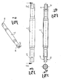
- Figur 1 -
- den Längsschnitt durch eine Rolle;
- Figur 2 -
- die perspektivische Ansicht einer ersten Achswelle;
- Figur 3 -
- die Ansicht der Achswelle nach
Figur 2 ; - Figur 4a -
- die Stirnansicht der Achswelle;
- Figur 4b -
- den Schnitt entlang der Linie IV-IV nach
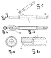
Figur 3 ; - Figur 5 -
- die perspektivische Darstellung einer zweiten Achswelle,
- Figur 6 -
- die Ansicht der Achswelle nach
Figur 5 ; - Figur 7a -
- die Stirnansicht der Achswelle;
- Figur 7b -
- den Schnitt entlang der Linie VII-VII nach
Figur 6 ; - Figur 8a -
- die vergrößerte Stirnansicht der Achswelle;
- Figur 8b -
- die Einzelheit VIII nach
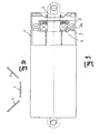
Figur 7b ; - Figur 9 -
- eine Rolle nach dem Stand der Technik;
- Figur 10 -
- die V-förmige Anordnung dreier Rollen zur Ausbildung einer Wanne.
-
Figur 9 zeigt eine herkömmliche Rolle, wie sie für Band- oder Gurtförderer Verwendung findet, die zum Transport von Schüttgut, wie Erze, Kies oder dergleichen verwendet werden. Solche Anlagen sind mehrere Kilometer lang und weisen eine Vielzahl parallel beabstandeter Rollen auf. Die Gurtbreite beträgt beispielsweise 2300 mm. Zur Ausbildung eines wannenförmigen Gurtes werden drei Rollen in V-Form (vgl.Figur 10 ) angeordnet. Die Rolle besteht aus dem hohlzylindrischen Rollenkörper 1, der Achswelle 2 und zwei an den Enden des Rollenkörpers 1 eingesetzten und mit der Innenwandung verschweißten Lagerhaltern 3a, in denen ein Sitz 3 für die Wälzlager 4 ausgebildet ist, die nach außen über eine Labyrinthdichtung 5 abgedichtet sind. - Die erfindungsgemäße Rolle besteht aus dem hohlzylindrischen Rollenkörper 1, der hohlen Achswelle 2 und den Wälzlagern 4a, 4b. Die beiden Enden des Rollenkörpers 1 sind durch Fließrollen nach axial innen umgeformt und bilden die Lagesitze 3 aus. Das Umformen der Enden geschieht, indem das den Rollenkörper 1 bildende Metallrohr über einen Innendorn gezogen und induktiv erwärmt wird. Das erwärmte Rohr wird dann in Rotation versetzt und ein entsprechend profiliertes Formwerkzeug fährt rotierend auf das Rohrende auf und bördelt die Wandung nach innen. Das Material der Wandung fließt beim Umformen in radiale Richtung, so dass die Wandstärke der Einstülpung 7 wesentlich größer ist als die Wandstärke des übrigen Rohres. Durch entsprechende Profilierung des Formwerkzeuges wandern beim Umformen die Enden der Einstülpung 7 nach radial außen und bilden einen Stützring 6 aus, durch den die Stabilität gegen Biegung des Rollenkörpers 1 bzw. der Lagersitze 3 erhöht wird. Nach dem Umformen werden in der Einstülpung 7 die Lagersitze 3 gefräst, die die Wälzlager 4a, 4b aufnehmen.
- Die Achswelle 2 ist hohl ausgebildet und ihr mittlerer Bereich ist gegenüber den Enden, die in den Wälzlagern 4a, 4b gelagert sind, im Durchmesser größer ausgebildet. In dem durchmessergrößeren Bereich der Achswelle 2 ist eine radiale Bohrung 8 eingebracht, über die der Luftaustausch zwischen dem Inneren 10 der Rolle und der Atmosphäre erfolgen kann.
- Nachdem die Lagersitze 3 gefräst worden sind, wird der Rollenkörper 1 außen überdreht und dann wird der Rollenkörper 1 ausgewuchtet. Hierzu wird ein Kunststoffschaum 9 in den rotierenden Rollenkörper 1 eingespritzt, der sich infolge der Fliehkräfte an der Innenwandung 1' über die volle axiale Länge anlegt und nach einer gewissen Zeit aushärtet, wobei sich entsprechend der Unwucht die Dicke der Polyurethanschicht 9 unterschiedlich ausbildet. In den Polyurethanschaum können hier nicht näher dargestellte Metallkugeln mit einem Durchmesser von 1,5 mm eingemischt sein. Solche Kugeln werden beispielsweise zum Stahlstrahlen benutzt.
- Die Enden der Achswelle 2 weisen zwei diametrale Abflachungen 11 auf, damit die Rolle verdrehsicher in ein hier nicht näher dargestelltes Gestell eingesetzt werden kann. Wie
Figuren 5 - 8b zeigen, können die Enden der Achswelle 2 zwischen den Abflachungen 11 einseitig eine radiale Abschrägung 12 aufweisen, die mit den Abflachungen 11 einen "Dreiflach" bilden. - Es ist ersichtlich, dass die Wandstärke der Achswelle 2 im mittleren Bereich dünner ist als an den Enden, in die über die Wälzlager 4a, 4b die Kraft eingeleitet wird. Die unterschiedliche Wandstärke wird dadurch erzielt, dass zunächst ein Rohr mit durchgehend zylindrischen Außendurchmesser und über die Länge konstanter Wandstärke auf einen Dorn aufgesetzt wird und im Bereich, der später der mittlere Bereich der Achswelle 2 ist, die Wandstärke dadurch reduziert wird, dass von außen ein Knetwerkzeug an das Rohr herangefahren wird. Der Innendurchmesser des Rohres bleibt konstant, der mittlere Bereich mit der reduzierten Wandstärke weist einen geringeren Außendurchmesser auf als die Rohrenden mit größerer Wandstärke. Dann wird gegen die Rohrenden von außen ein Werkzeug rotierend angefahren, das das Material nach radial innen umformt, bis die Enden denselben Außendurchmessern aufweisen wie der mittlere Bereich.
-
- 1
- Rollenkörper
- 1'
- Innenwandung
- 2
- Achswelle
- 3
- Lagersitz
- 3a
- Lagerhalter
- 4a
- Wälzlager
- 4b
- Wälzlager
- 5
- Labyrinthdichtung
- 6
- Stützring
- 7
- Einstülpung
- 8
- Bohrung
- 9
- Kunststoffschicht/Polyurethanschicht/Schaum
- 10
- Innenraum
- 11
- Abflachung
- 12
- radiale Schräge
Claims (9)
- Rolle für einen Förderer, insbesondere Gurt- oder Bandförderer, mit einem hohlzylindrischen Rollenkörper (1) und einer in mindestens zwei Lagern (4a, 4b) gelagerten Achswelle (2), wobei die Lager (4a, 4b) in je einem Lagersitz (3) angeordnet sind, dadurch gekennzeichnet, dass zur Ausbildung der Lagersitze (3) die Wandung des Rollenkörpers (1) an seinen beiden Enden durch Fließrollen axial nach innen umgeformt ist, wobei die Wandstärke der Wandung im Bereich der Lagersitze (3) zunimmt, und dass die axialen Enden (7) der nach innen umgeformten Wandung nach radial außen auslaufen und einen Stützring (6) ausbilden.
- Rolle nach Anspruch 1, dadurch gekennzeichnet, dass sich die Wandstärke der Wandung im Bereich der Lagersitze (3) mindestens verdoppelt.
- Rolle nach Anspruch 1 oder 2, dadurch gekennzeichnet, dass die Lagersitze (3) spanabhebend bearbeitet sind.
- Rolle nach einem oder mehreren der vorstehenden Ansprüche, dadurch gekennzeichnet, dass die Achswelle (2) hohl ausgebildet ist.
- Rolle nach Anspruch 4, dadurch gekennzeichnet, dass die Achswelle (2) mindestens eine radiale Bohrung (8) aufweist.
- Rolle nach einem oder mehreren der vorstehenden Ansprüche, dadurch gekennzeichnet, dass die Enden der Achswelle (2) mindestens zwei diametrale Abflachungen (11) aufweisen.
- Rolle nach Anspruch 6, dadurch gekennzeichnet, dass die Wandung der Achswelle (2) zwischen zwei Abflachungen (11) zumindest einseitig schräg nach radial innen verläuft.
- Rolle nach Anspruch 1, dadurch gekennzeichnet, dass an der Innenwandung (1') des Rollenkörpers (1) eine Kunststoffschicht (9) vorgesehen ist, die über die volle axiale Länge reicht.
- Rolle nach Anspruch 8, dadurch gekennzeichnet, dass in der Kunststoffschicht (9) Stahlkugeln eingebettet sind.
Priority Applications (1)
| Application Number | Priority Date | Filing Date | Title |
|---|---|---|---|
| PL04786723T PL1682437T3 (pl) | 2003-09-10 | 2004-09-07 | Rolka dla transportera, zwłaszcza transportera pasowego lub taśmowego |
Applications Claiming Priority (2)
| Application Number | Priority Date | Filing Date | Title |
|---|---|---|---|
| DE10342099A DE10342099A1 (de) | 2003-09-10 | 2003-09-10 | Rolle für einen Förderer, insbesondere Gurt- oder Bandförderer |
| PCT/DE2004/002001 WO2005023687A1 (de) | 2003-09-10 | 2004-09-07 | Rolle für einen förderer, insbesondere gurt- oder bandförderer |
Publications (3)
| Publication Number | Publication Date |
|---|---|
| EP1682437A1 EP1682437A1 (de) | 2006-07-26 |
| EP1682437B1 EP1682437B1 (de) | 2008-02-27 |
| EP1682437B2 true EP1682437B2 (de) | 2012-12-19 |
Family
ID=34258589
Family Applications (1)
| Application Number | Title | Priority Date | Filing Date |
|---|---|---|---|
| EP04786723A Expired - Lifetime EP1682437B2 (de) | 2003-09-10 | 2004-09-07 | Rolle für einen förderer, insbesondere gurt- oder bandförderer |
Country Status (10)
| Country | Link |
|---|---|
| EP (1) | EP1682437B2 (de) |
| AT (1) | ATE387390T1 (de) |
| AU (1) | AU2004270321B2 (de) |
| CA (1) | CA2538387C (de) |
| CZ (1) | CZ299905B6 (de) |
| DE (2) | DE10342099A1 (de) |
| ES (1) | ES2300824T3 (de) |
| PL (1) | PL1682437T3 (de) |
| PT (1) | PT1682437E (de) |
| WO (1) | WO2005023687A1 (de) |
Families Citing this family (7)
| Publication number | Priority date | Publication date | Assignee | Title |
|---|---|---|---|---|
| DE102006024125A1 (de) * | 2006-05-22 | 2007-11-29 | Gurtec Gmbh | Förderrolle |
| DE102006039983C5 (de) * | 2006-08-25 | 2023-03-30 | Rulmeca Faa Gmbh | Rolle |
| DE102008012752A1 (de) | 2008-03-05 | 2009-09-24 | Ab Skf | Rolle |
| CN101830344A (zh) * | 2010-04-26 | 2010-09-15 | 徐州中部矿山设备有限公司 | 压十二点轴承座 |
| DE102010037561A1 (de) * | 2010-09-15 | 2012-03-15 | Artur Küpper GmbH & Co. KG | Tragrolle für eine Trag- oder Förderbandanlage |
| DE102013018338A1 (de) | 2013-10-23 | 2015-04-23 | Komotzki Bergbaubedarf Gmbh | Tragrolle für Band- oder Gurtförderer |
| USD828419S1 (en) | 2016-02-23 | 2018-09-11 | Joy Global Underground Mining Llc | Idler roller |
Citations (8)
| Publication number | Priority date | Publication date | Assignee | Title |
|---|---|---|---|---|
| US1919495A (en) † | 1930-12-05 | 1933-07-25 | Lamson Co | Conveyer |
| US2030818A (en) † | 1932-03-07 | 1936-02-11 | Babcock & Wilcox Co | Method of forming a pressure vessel |
| USRE22465E (en) † | 1944-04-04 | Method and apparatus for shaping | ||
| US2446616A (en) † | 1945-12-07 | 1948-08-10 | Franklin N Smith | Bearing structure for conveyer rollers and the like |
| DE2827365A1 (de) † | 1978-06-22 | 1980-01-03 | Precismeca Gmbh | Tragrolle |
| DE3024750A1 (de) † | 1978-06-22 | 1982-02-04 | Precismeca Gesellschaft für Fördertechnik mbH, 6603 Sulzbach | Verfahren zum herstellen einer tragrolle |
| DE4431517C1 (de) † | 1994-08-11 | 1996-02-08 | Manfred Klever | Verfahren zum Formen von Endstücken an rohrförmigen Werkstücken aus Metall |
| DE19607010C1 (de) † | 1996-02-24 | 1996-12-12 | Gfu Ges Fuer Umformung Und Mas | Vorrichtung zum Formen eines Endstückes an einem rohrförmigen Werkstück aus Metall und damit hergestellter Druckbehälter |
Family Cites Families (14)
| Publication number | Priority date | Publication date | Assignee | Title |
|---|---|---|---|---|
| DE7204154U (de) * | 1972-04-27 | Hans Vom Stein Ohg | Rolle für Fördervorrichtungen | |
| DE7216869U (de) * | 1972-09-21 | Precismeca Ges Mbh | Trommel oder Tragrolle für Förderbänder un d dgl | |
| GB232854A (en) * | 1924-09-12 | 1925-04-30 | Timken Roller Bearing Co | Improvements in roller conveyors |
| US1958412A (en) * | 1932-01-09 | 1934-05-15 | Robins Conveying Belt Co | Idler roll |
| US3246357A (en) * | 1963-12-02 | 1966-04-19 | American Associated Companies | Roller mop |
| DE2338950B2 (de) * | 1973-08-01 | 1976-12-23 | Interroll Fördertechnik GmbH & Co KG, 5679 Dhünn Er : Specht, Dieter, 5679 Dhünn | Rolle fuer foerderanlagen |
| DE2723808A1 (de) * | 1977-05-26 | 1978-11-30 | Weserhuette Ag Eisenwerk | Tragrollenkoerper fuer tragrollen |
| GB1599670A (en) * | 1977-07-01 | 1981-10-07 | Nat Res Dev | Rotary mechanisms including locking devices |
| US4174031A (en) * | 1978-03-27 | 1979-11-13 | Rexnord Inc. | Lubricating system and method |
| DE3062860D1 (en) * | 1979-03-09 | 1983-06-01 | Skf Uk Ltd | End cap assemblies for conveyor rollers |
| US4311226A (en) * | 1980-01-28 | 1982-01-19 | Gifford-Hill & Company, Inc. | Trapped-axle conveyor roll |
| US4643300A (en) * | 1985-04-10 | 1987-02-17 | Continental Conveyor & Equipment Co. | Idler roll assembly |
| DE9403168U1 (de) * | 1994-02-25 | 1994-04-14 | Nedcon Magazijninrichting B.V., Doetinchem | Transportvorrichtung für schwere Gegenstände, insbesondere für beladene Industriepaletten |
| DE19833114A1 (de) * | 1998-07-23 | 2000-01-27 | Schaeffler Waelzlager Ohg | Rolle, insbesondere Druckrolle für Textilmaschinen |
-
2003
- 2003-09-10 DE DE10342099A patent/DE10342099A1/de not_active Ceased
-
2004
- 2004-09-07 EP EP04786723A patent/EP1682437B2/de not_active Expired - Lifetime
- 2004-09-07 AT AT04786723T patent/ATE387390T1/de not_active IP Right Cessation
- 2004-09-07 ES ES04786723T patent/ES2300824T3/es not_active Expired - Lifetime
- 2004-09-07 AU AU2004270321A patent/AU2004270321B2/en not_active Ceased
- 2004-09-07 WO PCT/DE2004/002001 patent/WO2005023687A1/de not_active Ceased
- 2004-09-07 PL PL04786723T patent/PL1682437T3/pl unknown
- 2004-09-07 DE DE502004006348T patent/DE502004006348D1/de not_active Expired - Lifetime
- 2004-09-07 PT PT04786723T patent/PT1682437E/pt unknown
- 2004-09-07 CA CA002538387A patent/CA2538387C/en not_active Expired - Lifetime
- 2004-09-07 CZ CZ20060139A patent/CZ299905B6/cs not_active IP Right Cessation
Patent Citations (8)
| Publication number | Priority date | Publication date | Assignee | Title |
|---|---|---|---|---|
| USRE22465E (en) † | 1944-04-04 | Method and apparatus for shaping | ||
| US1919495A (en) † | 1930-12-05 | 1933-07-25 | Lamson Co | Conveyer |
| US2030818A (en) † | 1932-03-07 | 1936-02-11 | Babcock & Wilcox Co | Method of forming a pressure vessel |
| US2446616A (en) † | 1945-12-07 | 1948-08-10 | Franklin N Smith | Bearing structure for conveyer rollers and the like |
| DE2827365A1 (de) † | 1978-06-22 | 1980-01-03 | Precismeca Gmbh | Tragrolle |
| DE3024750A1 (de) † | 1978-06-22 | 1982-02-04 | Precismeca Gesellschaft für Fördertechnik mbH, 6603 Sulzbach | Verfahren zum herstellen einer tragrolle |
| DE4431517C1 (de) † | 1994-08-11 | 1996-02-08 | Manfred Klever | Verfahren zum Formen von Endstücken an rohrförmigen Werkstücken aus Metall |
| DE19607010C1 (de) † | 1996-02-24 | 1996-12-12 | Gfu Ges Fuer Umformung Und Mas | Vorrichtung zum Formen eines Endstückes an einem rohrförmigen Werkstück aus Metall und damit hergestellter Druckbehälter |
Also Published As
| Publication number | Publication date |
|---|---|
| CA2538387C (en) | 2009-08-04 |
| EP1682437B1 (de) | 2008-02-27 |
| PL1682437T3 (pl) | 2008-07-31 |
| ATE387390T1 (de) | 2008-03-15 |
| PT1682437E (pt) | 2008-05-08 |
| EP1682437A1 (de) | 2006-07-26 |
| CZ299905B6 (cs) | 2008-12-29 |
| WO2005023687A1 (de) | 2005-03-17 |
| AU2004270321B2 (en) | 2008-03-06 |
| DE10342099A1 (de) | 2005-04-21 |
| ES2300824T3 (es) | 2008-06-16 |
| CZ2006139A3 (cs) | 2006-07-12 |
| CA2538387A1 (en) | 2005-03-17 |
| AU2004270321A1 (en) | 2005-03-17 |
| DE502004006348D1 (de) | 2008-04-10 |
Similar Documents
| Publication | Publication Date | Title |
|---|---|---|
| DE2315046C3 (de) | Einrichtung zum Verbinden der Schmierkanäle benachbarter Förderrollen | |
| DE102008013131B4 (de) | Lageranordnung für eine Tragrolle | |
| EP1682437B2 (de) | Rolle für einen förderer, insbesondere gurt- oder bandförderer | |
| DE3514316C2 (de) | ||
| DE3017942C2 (de) | Friktionsrollenbahn | |
| EP0110194B1 (de) | Vorrichtung zur Reduzierung der Wanddicke eines Rohres durch Walzen | |
| DE10035532A1 (de) | Windungsleger mit Legerohr für schnellbewegten Walzdraht | |
| DE2832966A1 (de) | Einrichtung zum drehfesten verbinden von mit wellen oder wellenzapfen umlaufenden maschinenteilen, beispielsweise walzen | |
| EP2740549B1 (de) | Treiberrolle einer Haspelanlage eines Walzwerkes | |
| EP1901980A1 (de) | Förderrolle | |
| DE19542850A1 (de) | Walze, insbesondere Transport-, Trag- oder Führungswalze, in Verbundbauweise | |
| DE3940925C2 (de) | ||
| DE3528588A1 (de) | Walze zum ausueben einer presskraft auf eine faserstoffbahn | |
| DE102010051057A1 (de) | Planetentrieb | |
| DE10004656C1 (de) | Wellenricht- und -härtemaschine | |
| DE102008064051A1 (de) | Tragrollenanordnung | |
| DE10024951C2 (de) | Rohrhalterung für Förderleitungen, insbesondere in pneumatischen Langsamfördersystemen | |
| DE102019135078A1 (de) | Wälzlagerring und Verfahren zur Bearbeitung eines Wälzlagerrings | |
| AT388718B (de) | Geraeuscharme stuetzrolle und ihre anordnung in einem rollengang | |
| DE2734712A1 (de) | Waelzlager, insbesondere grossen durchmessers | |
| DE19719063C2 (de) | Vorrichtung zur Herstellung eines Relining-Schlauchs | |
| EP2500467B1 (de) | Walze | |
| EP0829314A1 (de) | Lagerung für biegesteife Mantelwalzen auf einer Tragachse oder Tragwelle | |
| DE19803535C2 (de) | Zentrifuge und Leitung zum Zuführen und/oder Abführen mindestens eines Fluids von der Separationseinheit einer Zentrifuge zu einer ortsfesten Anschlußstelle | |
| DE29906184U1 (de) | Tragrolle |
Legal Events
| Date | Code | Title | Description |
|---|---|---|---|
| PUAI | Public reference made under article 153(3) epc to a published international application that has entered the european phase |
Free format text: ORIGINAL CODE: 0009012 |
|
| 17P | Request for examination filed |
Effective date: 20060606 |
|
| AK | Designated contracting states |
Kind code of ref document: A1 Designated state(s): AT BE BG CH CY CZ DE DK EE ES FI FR GB GR HU IE IT LI LU MC NL PL PT RO SE SI SK TR |
|
| DAX | Request for extension of the european patent (deleted) | ||
| GRAP | Despatch of communication of intention to grant a patent |
Free format text: ORIGINAL CODE: EPIDOSNIGR1 |
|
| GRAS | Grant fee paid |
Free format text: ORIGINAL CODE: EPIDOSNIGR3 |
|
| GRAA | (expected) grant |
Free format text: ORIGINAL CODE: 0009210 |
|
| AK | Designated contracting states |
Kind code of ref document: B1 Designated state(s): AT BE BG CH CY CZ DE DK EE ES FI FR GB GR HU IE IT LI LU MC NL PL PT RO SE SI SK TR |
|
| REG | Reference to a national code |
Ref country code: GB Ref legal event code: FG4D Free format text: NOT ENGLISH |
|
| REG | Reference to a national code |
Ref country code: CH Ref legal event code: EP |
|
| REG | Reference to a national code |
Ref country code: IE Ref legal event code: FG4D Free format text: LANGUAGE OF EP DOCUMENT: GERMAN |
|
| REF | Corresponds to: |
Ref document number: 502004006348 Country of ref document: DE Date of ref document: 20080410 Kind code of ref document: P |
|
| REG | Reference to a national code |
Ref country code: RO Ref legal event code: EPE |
|
| REG | Reference to a national code |
Ref country code: PT Ref legal event code: SC4A Free format text: AVAILABILITY OF NATIONAL TRANSLATION Effective date: 20080424 |
|
| RAP2 | Party data changed (patent owner data changed or rights of a patent transferred) |
Owner name: SANDVIK MINING AND CONSTRUCTION SUPPLY GMBH |
|
| REG | Reference to a national code |
Ref country code: GR Ref legal event code: EP Ref document number: 20080401094 Country of ref document: GR |
|
| REG | Reference to a national code |
Ref country code: SE Ref legal event code: TRGR |
|
| GBT | Gb: translation of ep patent filed (gb section 77(6)(a)/1977) |
Effective date: 20080501 |
|
| REG | Reference to a national code |
Ref country code: ES Ref legal event code: FG2A Ref document number: 2300824 Country of ref document: ES Kind code of ref document: T3 |
|
| NLT2 | Nl: modifications (of names), taken from the european patent patent bulletin |
Owner name: SANDVIK MINING AND CONSTRUCTION SUPPLY GMBH Effective date: 20080514 |
|
| REG | Reference to a national code |
Ref country code: PL Ref legal event code: T3 |
|
| REG | Reference to a national code |
Ref country code: PT Ref legal event code: PD4A Owner name: SANDVIK MINING AND CONSTRUCTION SUPPLY GMBH, DE Effective date: 20080428 |
|
| PLBI | Opposition filed |
Free format text: ORIGINAL CODE: 0009260 |
|
| PG25 | Lapsed in a contracting state [announced via postgrant information from national office to epo] |
Ref country code: SI Free format text: LAPSE BECAUSE OF FAILURE TO SUBMIT A TRANSLATION OF THE DESCRIPTION OR TO PAY THE FEE WITHIN THE PRESCRIBED TIME-LIMIT Effective date: 20080227 |
|
| 26 | Opposition filed |
Opponent name: PRECISMECA-MONTAN GES. FUER FOERDERTECHNIK MBH Effective date: 20080823 |
|
| PG25 | Lapsed in a contracting state [announced via postgrant information from national office to epo] |
Ref country code: SK Free format text: LAPSE BECAUSE OF FAILURE TO SUBMIT A TRANSLATION OF THE DESCRIPTION OR TO PAY THE FEE WITHIN THE PRESCRIBED TIME-LIMIT Effective date: 20080227 Ref country code: DK Free format text: LAPSE BECAUSE OF FAILURE TO SUBMIT A TRANSLATION OF THE DESCRIPTION OR TO PAY THE FEE WITHIN THE PRESCRIBED TIME-LIMIT Effective date: 20080227 |
|
| NLT1 | Nl: modifications of names registered in virtue of documents presented to the patent office pursuant to art. 16 a, paragraph 1 |
Owner name: SANDVIK MINING AND CONSTRUCTION SUPPLY GMBH |
|
| REG | Reference to a national code |
Ref country code: FR Ref legal event code: CD |
|
| ET | Fr: translation filed | ||
| PLBI | Opposition filed |
Free format text: ORIGINAL CODE: 0009260 |
|
| NLR1 | Nl: opposition has been filed with the epo |
Opponent name: PRECISMECA-MONTAN GES. FUER FOERDERTECHNIK MBH |
|
| PLBI | Opposition filed |
Free format text: ORIGINAL CODE: 0009260 |
|
| PLAX | Notice of opposition and request to file observation + time limit sent |
Free format text: ORIGINAL CODE: EPIDOSNOBS2 |
|
| REG | Reference to a national code |
Ref country code: HU Ref legal event code: AG4A Ref document number: E003822 Country of ref document: HU |
|
| 26 | Opposition filed |
Opponent name: ARTUR KUEPPER GMBH & CO. KG Effective date: 20081126 Opponent name: PRECISMECA-MONTAN GES. FUER FOERDERTECHNIK MBH Effective date: 20080823 |
|
| 26 | Opposition filed |
Opponent name: RULMECA FAA GMBH Effective date: 20081126 Opponent name: ARTUR KUEPPER GMBH & CO. KG Effective date: 20081126 Opponent name: PRECISMECA-MONTAN GES. FUER FOERDERTECHNIK MBH Effective date: 20080823 |
|
| NLR1 | Nl: opposition has been filed with the epo |
Opponent name: RULMECA FAA GMBH Opponent name: ARTUR KUEPPER GMBH & CO. KG Opponent name: PRECISMECA-MONTAN GES. FUER FOERDERTECHNIK MBH |
|
| PG25 | Lapsed in a contracting state [announced via postgrant information from national office to epo] |
Ref country code: EE Free format text: LAPSE BECAUSE OF FAILURE TO SUBMIT A TRANSLATION OF THE DESCRIPTION OR TO PAY THE FEE WITHIN THE PRESCRIBED TIME-LIMIT Effective date: 20080227 Ref country code: MC Free format text: LAPSE BECAUSE OF NON-PAYMENT OF DUE FEES Effective date: 20080930 |
|
| REG | Reference to a national code |
Ref country code: CH Ref legal event code: PL |
|
| PLAF | Information modified related to communication of a notice of opposition and request to file observations + time limit |
Free format text: ORIGINAL CODE: EPIDOSCOBS2 |
|
| PLBB | Reply of patent proprietor to notice(s) of opposition received |
Free format text: ORIGINAL CODE: EPIDOSNOBS3 |
|
| PG25 | Lapsed in a contracting state [announced via postgrant information from national office to epo] |
Ref country code: CY Free format text: LAPSE BECAUSE OF FAILURE TO SUBMIT A TRANSLATION OF THE DESCRIPTION OR TO PAY THE FEE WITHIN THE PRESCRIBED TIME-LIMIT Effective date: 20080227 |
|
| PLAB | Opposition data, opponent's data or that of the opponent's representative modified |
Free format text: ORIGINAL CODE: 0009299OPPO |
|
| R26 | Opposition filed (corrected) |
Opponent name: RULMECA GERMANY GMBH Effective date: 20081126 Opponent name: ARTUR KUEPPER GMBH & CO. KG Effective date: 20081126 Opponent name: PRECISMECA-MONTAN GES. FUER FOERDERTECHNIK MBH Effective date: 20080823 |
|
| PG25 | Lapsed in a contracting state [announced via postgrant information from national office to epo] |
Ref country code: LI Free format text: LAPSE BECAUSE OF NON-PAYMENT OF DUE FEES Effective date: 20080930 Ref country code: CH Free format text: LAPSE BECAUSE OF NON-PAYMENT OF DUE FEES Effective date: 20080930 Ref country code: AT Free format text: LAPSE BECAUSE OF NON-PAYMENT OF DUE FEES Effective date: 20080907 |
|
| NLR1 | Nl: opposition has been filed with the epo |
Opponent name: RULMECA GERMANY GMBH Opponent name: PRECISMECA-MONTAN GES. FUER FOERDERTECHNIK MBH Opponent name: ARTUR KUEPPER GMBH & CO. KG |
|
| PG25 | Lapsed in a contracting state [announced via postgrant information from national office to epo] |
Ref country code: LU Free format text: LAPSE BECAUSE OF NON-PAYMENT OF DUE FEES Effective date: 20080907 |
|
| PGFP | Annual fee paid to national office [announced via postgrant information from national office to epo] |
Ref country code: CZ Payment date: 20110829 Year of fee payment: 8 |
|
| PLAB | Opposition data, opponent's data or that of the opponent's representative modified |
Free format text: ORIGINAL CODE: 0009299OPPO |
|
| R26 | Opposition filed (corrected) |
Opponent name: RULMECA GERMANY GMBH Effective date: 20081126 Opponent name: ARTUR KUEPPER GMBH & CO. KG Effective date: 20081126 Opponent name: PRECISMECA-MONTAN GES. FUER FOERDERTECHNIK MBH Effective date: 20080823 |
|
| PLAB | Opposition data, opponent's data or that of the opponent's representative modified |
Free format text: ORIGINAL CODE: 0009299OPPO |
|
| R26 | Opposition filed (corrected) |
Opponent name: RULMECA GERMANY GMBH Effective date: 20081126 Opponent name: PRECISMECA-MONTAN GES. FUER FOERDERTECHNIK MBH Effective date: 20080823 Opponent name: ARTUR KUEPPER GMBH & CO. KG Effective date: 20081126 |
|
| PGFP | Annual fee paid to national office [announced via postgrant information from national office to epo] |
Ref country code: FI Payment date: 20120919 Year of fee payment: 9 Ref country code: RO Payment date: 20120903 Year of fee payment: 9 Ref country code: IE Payment date: 20120918 Year of fee payment: 9 Ref country code: SE Payment date: 20120920 Year of fee payment: 9 Ref country code: GB Payment date: 20120920 Year of fee payment: 9 |
|
| PUAH | Patent maintained in amended form |
Free format text: ORIGINAL CODE: 0009272 |
|
| STAA | Information on the status of an ep patent application or granted ep patent |
Free format text: STATUS: PATENT MAINTAINED AS AMENDED |
|
| PGFP | Annual fee paid to national office [announced via postgrant information from national office to epo] |
Ref country code: TR Payment date: 20120903 Year of fee payment: 9 Ref country code: GR Payment date: 20120927 Year of fee payment: 9 Ref country code: PL Payment date: 20120724 Year of fee payment: 9 Ref country code: BG Payment date: 20120924 Year of fee payment: 9 |
|
| 27A | Patent maintained in amended form |
Effective date: 20121219 |
|
| AK | Designated contracting states |
Kind code of ref document: B2 Designated state(s): AT BE BG CH CY CZ DE DK EE ES FI FR GB GR HU IE IT LI LU MC NL PL PT RO SE SI SK TR |
|
| PGFP | Annual fee paid to national office [announced via postgrant information from national office to epo] |
Ref country code: ES Payment date: 20120924 Year of fee payment: 9 Ref country code: HU Payment date: 20120905 Year of fee payment: 9 Ref country code: IT Payment date: 20120925 Year of fee payment: 9 |
|
| PGFP | Annual fee paid to national office [announced via postgrant information from national office to epo] |
Ref country code: NL Payment date: 20120920 Year of fee payment: 9 Ref country code: PT Payment date: 20120307 Year of fee payment: 9 Ref country code: BE Payment date: 20120919 Year of fee payment: 9 Ref country code: FR Payment date: 20121008 Year of fee payment: 9 |
|
| REG | Reference to a national code |
Ref country code: DE Ref legal event code: R102 Ref document number: 502004006348 Country of ref document: DE Effective date: 20121219 |
|
| REG | Reference to a national code |
Ref country code: PT Ref legal event code: MP4A Effective date: 20130419 |
|
| PG25 | Lapsed in a contracting state [announced via postgrant information from national office to epo] |
Ref country code: FI Free format text: LAPSE BECAUSE OF FAILURE TO SUBMIT A TRANSLATION OF THE DESCRIPTION OR TO PAY THE FEE WITHIN THE PRESCRIBED TIME-LIMIT Effective date: 20121219 Ref country code: ES Free format text: LAPSE BECAUSE OF FAILURE TO SUBMIT A TRANSLATION OF THE DESCRIPTION OR TO PAY THE FEE WITHIN THE PRESCRIBED TIME-LIMIT Effective date: 20080607 |
|
| REG | Reference to a national code |
Ref country code: SE Ref legal event code: NAV |
|
| REG | Reference to a national code |
Ref country code: NL Ref legal event code: VDEP Effective date: 20121219 |
|
| PG25 | Lapsed in a contracting state [announced via postgrant information from national office to epo] |
Ref country code: GR Free format text: LAPSE BECAUSE OF FAILURE TO SUBMIT A TRANSLATION OF THE DESCRIPTION OR TO PAY THE FEE WITHIN THE PRESCRIBED TIME-LIMIT Effective date: 20130320 |
|
| PG25 | Lapsed in a contracting state [announced via postgrant information from national office to epo] |
Ref country code: ES Free format text: LAPSE BECAUSE OF FAILURE TO SUBMIT A TRANSLATION OF THE DESCRIPTION OR TO PAY THE FEE WITHIN THE PRESCRIBED TIME-LIMIT Effective date: 20130330 |
|
| PG25 | Lapsed in a contracting state [announced via postgrant information from national office to epo] |
Ref country code: NL Free format text: LAPSE BECAUSE OF FAILURE TO SUBMIT A TRANSLATION OF THE DESCRIPTION OR TO PAY THE FEE WITHIN THE PRESCRIBED TIME-LIMIT Effective date: 20121219 Ref country code: PT Free format text: LAPSE BECAUSE OF FAILURE TO SUBMIT A TRANSLATION OF THE DESCRIPTION OR TO PAY THE FEE WITHIN THE PRESCRIBED TIME-LIMIT Effective date: 20130429 |
|
| BERE | Be: lapsed |
Owner name: SANDVIK MINING AND CONSTRUCTION SUPPLY G.M.B.H. Effective date: 20130930 |
|
| PG25 | Lapsed in a contracting state [announced via postgrant information from national office to epo] |
Ref country code: CZ Free format text: LAPSE BECAUSE OF FAILURE TO SUBMIT A TRANSLATION OF THE DESCRIPTION OR TO PAY THE FEE WITHIN THE PRESCRIBED TIME-LIMIT Effective date: 20080227 Ref country code: RO Free format text: LAPSE BECAUSE OF NON-PAYMENT OF DUE FEES Effective date: 20130907 |
|
| GBPC | Gb: european patent ceased through non-payment of renewal fee |
Effective date: 20130907 |
|
| REG | Reference to a national code |
Ref country code: FR Ref legal event code: ST Effective date: 20140530 |
|
| REG | Reference to a national code |
Ref country code: IE Ref legal event code: MM4A |
|
| PG25 | Lapsed in a contracting state [announced via postgrant information from national office to epo] |
Ref country code: IE Free format text: LAPSE BECAUSE OF NON-PAYMENT OF DUE FEES Effective date: 20130907 Ref country code: GB Free format text: LAPSE BECAUSE OF NON-PAYMENT OF DUE FEES Effective date: 20130907 Ref country code: BE Free format text: LAPSE BECAUSE OF NON-PAYMENT OF DUE FEES Effective date: 20130930 |
|
| PG25 | Lapsed in a contracting state [announced via postgrant information from national office to epo] |
Ref country code: IT Free format text: LAPSE BECAUSE OF NON-PAYMENT OF DUE FEES Effective date: 20130907 Ref country code: FR Free format text: LAPSE BECAUSE OF NON-PAYMENT OF DUE FEES Effective date: 20130930 |
|
| PG25 | Lapsed in a contracting state [announced via postgrant information from national office to epo] |
Ref country code: HU Free format text: LAPSE BECAUSE OF NON-PAYMENT OF DUE FEES Effective date: 20130908 |
|
| PG25 | Lapsed in a contracting state [announced via postgrant information from national office to epo] |
Ref country code: BG Free format text: LAPSE BECAUSE OF NON-PAYMENT OF DUE FEES Effective date: 20130930 |
|
| REG | Reference to a national code |
Ref country code: DE Ref legal event code: R082 Ref document number: 502004006348 Country of ref document: DE Representative=s name: GRAMM, LINS & PARTNER PATENT- UND RECHTSANWAEL, DE |
|
| PG25 | Lapsed in a contracting state [announced via postgrant information from national office to epo] |
Ref country code: SE Free format text: LAPSE BECAUSE OF NON-PAYMENT OF DUE FEES Effective date: 20130908 |
|
| PG25 | Lapsed in a contracting state [announced via postgrant information from national office to epo] |
Ref country code: TR Free format text: LAPSE BECAUSE OF NON-PAYMENT OF DUE FEES Effective date: 20130907 |
|
| PG25 | Lapsed in a contracting state [announced via postgrant information from national office to epo] |
Ref country code: CZ Free format text: THE PATENT HAS BEEN ANNULLED BY A DECISION OF A NATIONAL AUTHORITY Effective date: 20080227 |
|
| PG25 | Lapsed in a contracting state [announced via postgrant information from national office to epo] |
Ref country code: PL Free format text: THE PATENT HAS BEEN ANNULLED BY A DECISION OF A NATIONAL AUTHORITY Effective date: 20080227 |
|
| REG | Reference to a national code |
Ref country code: DE Ref legal event code: R081 Ref document number: 502004006348 Country of ref document: DE Owner name: CONV AUSTRALIA HOLDING PTY LTD, AU Free format text: FORMER OWNER: SANDVIK MINING AND CONSTRUCTION SUPPLY GMBH, 38170 SCHOEPPENSTEDT, DE |
|
| PGFP | Annual fee paid to national office [announced via postgrant information from national office to epo] |
Ref country code: DE Payment date: 20230920 Year of fee payment: 20 |
|
| REG | Reference to a national code |
Ref country code: DE Ref legal event code: R071 Ref document number: 502004006348 Country of ref document: DE |