EP1681071B1 - Apparatus for producing a breathing circuit component - Google Patents
Apparatus for producing a breathing circuit component Download PDFInfo
- Publication number
- EP1681071B1 EP1681071B1 EP06005171A EP06005171A EP1681071B1 EP 1681071 B1 EP1681071 B1 EP 1681071B1 EP 06005171 A EP06005171 A EP 06005171A EP 06005171 A EP06005171 A EP 06005171A EP 1681071 B1 EP1681071 B1 EP 1681071B1
- Authority
- EP
- European Patent Office
- Prior art keywords
- bead
- conduit
- laying head
- breathable
- thread
- Prior art date
- Legal status (The legal status is an assumption and is not a legal conclusion. Google has not performed a legal analysis and makes no representation as to the accuracy of the status listed.)
- Expired - Lifetime
Links
Images


Classifications
-
- A—HUMAN NECESSITIES
- A61—MEDICAL OR VETERINARY SCIENCE; HYGIENE
- A61M—DEVICES FOR INTRODUCING MEDIA INTO, OR ONTO, THE BODY; DEVICES FOR TRANSDUCING BODY MEDIA OR FOR TAKING MEDIA FROM THE BODY; DEVICES FOR PRODUCING OR ENDING SLEEP OR STUPOR
- A61M16/00—Devices for influencing the respiratory system of patients by gas treatment, e.g. ventilators; Tracheal tubes
- A61M16/08—Bellows; Connecting tubes ; Water traps; Patient circuits
- A61M16/0808—Condensation traps
-
- A—HUMAN NECESSITIES
- A61—MEDICAL OR VETERINARY SCIENCE; HYGIENE
- A61M—DEVICES FOR INTRODUCING MEDIA INTO, OR ONTO, THE BODY; DEVICES FOR TRANSDUCING BODY MEDIA OR FOR TAKING MEDIA FROM THE BODY; DEVICES FOR PRODUCING OR ENDING SLEEP OR STUPOR
- A61M16/00—Devices for influencing the respiratory system of patients by gas treatment, e.g. ventilators; Tracheal tubes
- A61M16/08—Bellows; Connecting tubes ; Water traps; Patient circuits
- A61M16/0816—Joints or connectors
- A61M16/0833—T- or Y-type connectors, e.g. Y-piece
-
- A—HUMAN NECESSITIES
- A61—MEDICAL OR VETERINARY SCIENCE; HYGIENE
- A61M—DEVICES FOR INTRODUCING MEDIA INTO, OR ONTO, THE BODY; DEVICES FOR TRANSDUCING BODY MEDIA OR FOR TAKING MEDIA FROM THE BODY; DEVICES FOR PRODUCING OR ENDING SLEEP OR STUPOR
- A61M16/00—Devices for influencing the respiratory system of patients by gas treatment, e.g. ventilators; Tracheal tubes
- A61M16/08—Bellows; Connecting tubes ; Water traps; Patient circuits
- A61M16/0875—Connecting tubes
-
- A—HUMAN NECESSITIES
- A61—MEDICAL OR VETERINARY SCIENCE; HYGIENE
- A61M—DEVICES FOR INTRODUCING MEDIA INTO, OR ONTO, THE BODY; DEVICES FOR TRANSDUCING BODY MEDIA OR FOR TAKING MEDIA FROM THE BODY; DEVICES FOR PRODUCING OR ENDING SLEEP OR STUPOR
- A61M16/00—Devices for influencing the respiratory system of patients by gas treatment, e.g. ventilators; Tracheal tubes
- A61M16/08—Bellows; Connecting tubes ; Water traps; Patient circuits
- A61M16/0883—Circuit type
-
- A—HUMAN NECESSITIES
- A61—MEDICAL OR VETERINARY SCIENCE; HYGIENE
- A61M—DEVICES FOR INTRODUCING MEDIA INTO, OR ONTO, THE BODY; DEVICES FOR TRANSDUCING BODY MEDIA OR FOR TAKING MEDIA FROM THE BODY; DEVICES FOR PRODUCING OR ENDING SLEEP OR STUPOR
- A61M16/00—Devices for influencing the respiratory system of patients by gas treatment, e.g. ventilators; Tracheal tubes
- A61M16/10—Preparation of respiratory gases or vapours
- A61M16/1045—Devices for humidifying or heating the inspired gas by using recovered moisture or heat from the expired gas
-
- A—HUMAN NECESSITIES
- A61—MEDICAL OR VETERINARY SCIENCE; HYGIENE
- A61M—DEVICES FOR INTRODUCING MEDIA INTO, OR ONTO, THE BODY; DEVICES FOR TRANSDUCING BODY MEDIA OR FOR TAKING MEDIA FROM THE BODY; DEVICES FOR PRODUCING OR ENDING SLEEP OR STUPOR
- A61M16/00—Devices for influencing the respiratory system of patients by gas treatment, e.g. ventilators; Tracheal tubes
- A61M16/10—Preparation of respiratory gases or vapours
- A61M16/105—Filters
- A61M16/106—Filters in a path
- A61M16/1065—Filters in a path in the expiratory path
-
- B—PERFORMING OPERATIONS; TRANSPORTING
- B29—WORKING OF PLASTICS; WORKING OF SUBSTANCES IN A PLASTIC STATE IN GENERAL
- B29C—SHAPING OR JOINING OF PLASTICS; SHAPING OF MATERIAL IN A PLASTIC STATE, NOT OTHERWISE PROVIDED FOR; AFTER-TREATMENT OF THE SHAPED PRODUCTS, e.g. REPAIRING
- B29C48/00—Extrusion moulding, i.e. expressing the moulding material through a die or nozzle which imparts the desired form; Apparatus therefor
- B29C48/001—Combinations of extrusion moulding with other shaping operations
- B29C48/0019—Combinations of extrusion moulding with other shaping operations combined with shaping by flattening, folding or bending
-
- B—PERFORMING OPERATIONS; TRANSPORTING
- B29—WORKING OF PLASTICS; WORKING OF SUBSTANCES IN A PLASTIC STATE IN GENERAL
- B29C—SHAPING OR JOINING OF PLASTICS; SHAPING OF MATERIAL IN A PLASTIC STATE, NOT OTHERWISE PROVIDED FOR; AFTER-TREATMENT OF THE SHAPED PRODUCTS, e.g. REPAIRING
- B29C48/00—Extrusion moulding, i.e. expressing the moulding material through a die or nozzle which imparts the desired form; Apparatus therefor
- B29C48/25—Component parts, details or accessories; Auxiliary operations
- B29C48/30—Extrusion nozzles or dies
- B29C48/301—Extrusion nozzles or dies having reciprocating, oscillating or rotating parts
-
- B—PERFORMING OPERATIONS; TRANSPORTING
- B29—WORKING OF PLASTICS; WORKING OF SUBSTANCES IN A PLASTIC STATE IN GENERAL
- B29C—SHAPING OR JOINING OF PLASTICS; SHAPING OF MATERIAL IN A PLASTIC STATE, NOT OTHERWISE PROVIDED FOR; AFTER-TREATMENT OF THE SHAPED PRODUCTS, e.g. REPAIRING
- B29C48/00—Extrusion moulding, i.e. expressing the moulding material through a die or nozzle which imparts the desired form; Apparatus therefor
- B29C48/25—Component parts, details or accessories; Auxiliary operations
- B29C48/30—Extrusion nozzles or dies
- B29C48/32—Extrusion nozzles or dies with annular openings, e.g. for forming tubular articles
-
- B—PERFORMING OPERATIONS; TRANSPORTING
- B29—WORKING OF PLASTICS; WORKING OF SUBSTANCES IN A PLASTIC STATE IN GENERAL
- B29C—SHAPING OR JOINING OF PLASTICS; SHAPING OF MATERIAL IN A PLASTIC STATE, NOT OTHERWISE PROVIDED FOR; AFTER-TREATMENT OF THE SHAPED PRODUCTS, e.g. REPAIRING
- B29C53/00—Shaping by bending, folding, twisting, straightening or flattening; Apparatus therefor
- B29C53/56—Winding and joining, e.g. winding spirally
- B29C53/58—Winding and joining, e.g. winding spirally helically
- B29C53/583—Winding and joining, e.g. winding spirally helically for making tubular articles with particular features
- B29C53/585—Winding and joining, e.g. winding spirally helically for making tubular articles with particular features the cross-section varying along their axis, e.g. tapered, with ribs, or threads, with socket-ends
-
- B—PERFORMING OPERATIONS; TRANSPORTING
- B29—WORKING OF PLASTICS; WORKING OF SUBSTANCES IN A PLASTIC STATE IN GENERAL
- B29C—SHAPING OR JOINING OF PLASTICS; SHAPING OF MATERIAL IN A PLASTIC STATE, NOT OTHERWISE PROVIDED FOR; AFTER-TREATMENT OF THE SHAPED PRODUCTS, e.g. REPAIRING
- B29C53/00—Shaping by bending, folding, twisting, straightening or flattening; Apparatus therefor
- B29C53/56—Winding and joining, e.g. winding spirally
- B29C53/58—Winding and joining, e.g. winding spirally helically
- B29C53/60—Winding and joining, e.g. winding spirally helically using internal forming surfaces, e.g. mandrels
- B29C53/62—Winding and joining, e.g. winding spirally helically using internal forming surfaces, e.g. mandrels rotatable about the winding axis
- B29C53/64—Winding and joining, e.g. winding spirally helically using internal forming surfaces, e.g. mandrels rotatable about the winding axis and moving axially
-
- B—PERFORMING OPERATIONS; TRANSPORTING
- B29—WORKING OF PLASTICS; WORKING OF SUBSTANCES IN A PLASTIC STATE IN GENERAL
- B29C—SHAPING OR JOINING OF PLASTICS; SHAPING OF MATERIAL IN A PLASTIC STATE, NOT OTHERWISE PROVIDED FOR; AFTER-TREATMENT OF THE SHAPED PRODUCTS, e.g. REPAIRING
- B29C53/00—Shaping by bending, folding, twisting, straightening or flattening; Apparatus therefor
- B29C53/56—Winding and joining, e.g. winding spirally
- B29C53/58—Winding and joining, e.g. winding spirally helically
- B29C53/60—Winding and joining, e.g. winding spirally helically using internal forming surfaces, e.g. mandrels
- B29C53/68—Winding and joining, e.g. winding spirally helically using internal forming surfaces, e.g. mandrels with rotatable winding feed member
- B29C53/70—Winding and joining, e.g. winding spirally helically using internal forming surfaces, e.g. mandrels with rotatable winding feed member and moving axially
-
- A—HUMAN NECESSITIES
- A61—MEDICAL OR VETERINARY SCIENCE; HYGIENE
- A61M—DEVICES FOR INTRODUCING MEDIA INTO, OR ONTO, THE BODY; DEVICES FOR TRANSDUCING BODY MEDIA OR FOR TAKING MEDIA FROM THE BODY; DEVICES FOR PRODUCING OR ENDING SLEEP OR STUPOR
- A61M39/00—Tubes, tube connectors, tube couplings, valves, access sites or the like, specially adapted for medical use
- A61M39/08—Tubes; Storage means specially adapted therefor
- A61M2039/082—Multi-lumen tubes
-
- A—HUMAN NECESSITIES
- A61—MEDICAL OR VETERINARY SCIENCE; HYGIENE
- A61M—DEVICES FOR INTRODUCING MEDIA INTO, OR ONTO, THE BODY; DEVICES FOR TRANSDUCING BODY MEDIA OR FOR TAKING MEDIA FROM THE BODY; DEVICES FOR PRODUCING OR ENDING SLEEP OR STUPOR
- A61M2205/00—General characteristics of the apparatus
- A61M2205/75—General characteristics of the apparatus with filters
- A61M2205/7536—General characteristics of the apparatus with filters allowing gas passage, but preventing liquid passage, e.g. liquophobic, hydrophobic, water-repellent membranes
-
- A—HUMAN NECESSITIES
- A61—MEDICAL OR VETERINARY SCIENCE; HYGIENE
- A61M—DEVICES FOR INTRODUCING MEDIA INTO, OR ONTO, THE BODY; DEVICES FOR TRANSDUCING BODY MEDIA OR FOR TAKING MEDIA FROM THE BODY; DEVICES FOR PRODUCING OR ENDING SLEEP OR STUPOR
- A61M2207/00—Methods of manufacture, assembly or production
- A61M2207/10—Device therefor
-
- A—HUMAN NECESSITIES
- A61—MEDICAL OR VETERINARY SCIENCE; HYGIENE
- A61M—DEVICES FOR INTRODUCING MEDIA INTO, OR ONTO, THE BODY; DEVICES FOR TRANSDUCING BODY MEDIA OR FOR TAKING MEDIA FROM THE BODY; DEVICES FOR PRODUCING OR ENDING SLEEP OR STUPOR
- A61M2230/00—Measuring parameters of the user
- A61M2230/40—Respiratory characteristics
- A61M2230/43—Composition of exhalation
- A61M2230/432—Composition of exhalation partial CO2 pressure (P-CO2)
-
- A—HUMAN NECESSITIES
- A61—MEDICAL OR VETERINARY SCIENCE; HYGIENE
- A61M—DEVICES FOR INTRODUCING MEDIA INTO, OR ONTO, THE BODY; DEVICES FOR TRANSDUCING BODY MEDIA OR FOR TAKING MEDIA FROM THE BODY; DEVICES FOR PRODUCING OR ENDING SLEEP OR STUPOR
- A61M39/00—Tubes, tube connectors, tube couplings, valves, access sites or the like, specially adapted for medical use
- A61M39/08—Tubes; Storage means specially adapted therefor
-
- B—PERFORMING OPERATIONS; TRANSPORTING
- B29—WORKING OF PLASTICS; WORKING OF SUBSTANCES IN A PLASTIC STATE IN GENERAL
- B29C—SHAPING OR JOINING OF PLASTICS; SHAPING OF MATERIAL IN A PLASTIC STATE, NOT OTHERWISE PROVIDED FOR; AFTER-TREATMENT OF THE SHAPED PRODUCTS, e.g. REPAIRING
- B29C48/00—Extrusion moulding, i.e. expressing the moulding material through a die or nozzle which imparts the desired form; Apparatus therefor
- B29C48/03—Extrusion moulding, i.e. expressing the moulding material through a die or nozzle which imparts the desired form; Apparatus therefor characterised by the shape of the extruded material at extrusion
- B29C48/04—Particle-shaped
-
- B—PERFORMING OPERATIONS; TRANSPORTING
- B29—WORKING OF PLASTICS; WORKING OF SUBSTANCES IN A PLASTIC STATE IN GENERAL
- B29C—SHAPING OR JOINING OF PLASTICS; SHAPING OF MATERIAL IN A PLASTIC STATE, NOT OTHERWISE PROVIDED FOR; AFTER-TREATMENT OF THE SHAPED PRODUCTS, e.g. REPAIRING
- B29C48/00—Extrusion moulding, i.e. expressing the moulding material through a die or nozzle which imparts the desired form; Apparatus therefor
- B29C48/03—Extrusion moulding, i.e. expressing the moulding material through a die or nozzle which imparts the desired form; Apparatus therefor characterised by the shape of the extruded material at extrusion
- B29C48/07—Flat, e.g. panels
-
- B—PERFORMING OPERATIONS; TRANSPORTING
- B29—WORKING OF PLASTICS; WORKING OF SUBSTANCES IN A PLASTIC STATE IN GENERAL
- B29C—SHAPING OR JOINING OF PLASTICS; SHAPING OF MATERIAL IN A PLASTIC STATE, NOT OTHERWISE PROVIDED FOR; AFTER-TREATMENT OF THE SHAPED PRODUCTS, e.g. REPAIRING
- B29C48/00—Extrusion moulding, i.e. expressing the moulding material through a die or nozzle which imparts the desired form; Apparatus therefor
- B29C48/03—Extrusion moulding, i.e. expressing the moulding material through a die or nozzle which imparts the desired form; Apparatus therefor characterised by the shape of the extruded material at extrusion
- B29C48/09—Articles with cross-sections having partially or fully enclosed cavities, e.g. pipes or channels
-
- B—PERFORMING OPERATIONS; TRANSPORTING
- B29—WORKING OF PLASTICS; WORKING OF SUBSTANCES IN A PLASTIC STATE IN GENERAL
- B29L—INDEXING SCHEME ASSOCIATED WITH SUBCLASS B29C, RELATING TO PARTICULAR ARTICLES
- B29L2023/00—Tubular articles
- B29L2023/005—Hoses, i.e. flexible
- B29L2023/007—Medical tubes other than catheters
-
- B—PERFORMING OPERATIONS; TRANSPORTING
- B29—WORKING OF PLASTICS; WORKING OF SUBSTANCES IN A PLASTIC STATE IN GENERAL
- B29L—INDEXING SCHEME ASSOCIATED WITH SUBCLASS B29C, RELATING TO PARTICULAR ARTICLES
- B29L2031/00—Other particular articles
- B29L2031/753—Medical equipment; Accessories therefor
Definitions
- the present invention relates to components for breathing circuits and in particular to components for use in the expiratory arm of a breathing circuit. More particularly, the invention relates to an apparatus for forming a breathing circuit conduit.
- GB 587,163 discloses a multi-layer helically wound tube and apparatus for forming the same.
- the tube is characterised in that sandwiched between the inner and outer helically wound layers, is longitudinal band which has a label or other indicia printed on it.
- the outer helical layer is constructed from a transparent material so that the indicia on the longitudinal layer are visible.
- US 5,454,061 discloses a helically wound and helically ribbed plastic tube and apparatus for forming the same.
- a plastic ribbon is wound about an axis into a tube with one edge of each lap over lapping and heat bonded to an edge of the preceding lap as the tubing is rotated.
- a conductive wire is embedded in the ribbon and a bead is applied and heat sealed onto the tubing.
- an apparatus for forming a breathing circuit conduit comprising:
- breathable material that allows the passage of water vapour without allowing the passage of liquid water or respiratory gases. Materials may be breathable due to their composition, physical structure a combination thereof.
- conduit 4 of the expiratory limb of a breathing circuit is formed having one or more longitudinal strips 2, 3 of breathable membrane as part of the wall 1 thereof.
- One possible material for the breathable regions is an activated perfluorinated polymer material having extreme hydrophilic properties.
- An example of this polymer material is marketed under the trade mark NAFION by DuPont Fluoro products of Fayetteville USA. This material is useful due to its extreme hydrophilic properties and due to its ability to be extruded, particularly to be co-extruded in combination with other plastic materials.
- the preferred material is a hydrophilic polyester block copolymer formed into a homogeneous flat film.
- An example of such a film is sold under the brand SYMPATEX. This material is particularly suited to thin film productions.
- FIG. 6 an alternative configuration of the expiratory limb is shown in which the entire flexible wall membrane of the conduit is formed from a breathable plastic membrane, extruded and wound helically with edges of adjacent turns sealed to one another.
- FIGS 9a to 9i , 7 and 8 Further variations on the configuration of Figure 6 are depictured in Figures 9a to 9i , 7 and 8 .
- the flexible wall membrane of the conduit is supplemented by reinforcing to provide resistance to lateral crushing and to longitudinal stretching of the conduit.
- Further variations are shown including variants having multiple breathable plastic membranes. Apparatus for forming such conduits is described with reference to Figures 10 , 11 and 12 .
- an expiratory limb conduit according to the present invention is provided as the inner conduit of a coaxial conduit configuration, such that expiratory gases and inspiratory gases each flow in one of the inner conduit or the space between the inner conduit and the outer conduit and in use water vapour but not liquid water is transmitted from the expiratory gases passageway to the inspiratory gases passageway.
- a further component is a catheter mount.
- the application of the invention to a catheter mount is described with reference to Figure 13 .
- one or more longitudinal sections (lengths) of the conduit being formed of the breathable material or isolated regions of the conduit wall being formed from the material.
- the configurations described herein are preferred due to their apparent simplicity of manufacture, being capable of linear manufacture, either by continuous stitching, gluing or welding, by co extrusion or by winding onto a former.
- conduit wall be manufactured to have a relatively low wall thickness, so much so that the conduit wall membrane may be insufficiently sturdy to be self supporting.
- a spiral or helical internal (or external) reinforcing members may be provided outside (or inside) the tubular membrane to provide support.
- the helical, spiral or hoop supporting members may for example be formed from polymer plastic materials, such as the material used in the wall of the conduit (not being the breathable regions), or alternatively may for example be a metal wire support, such as drawn steel wire.
- the conduit shown in Figure 2 may be formed in any one of a number of methods.
- the tubular membrane may be supplied in a continuous tube.
- the membrane Supplied as extruded tape, the membrane may be wound helically onto a former.
- the helical supporting rib provided in a semi molten state is then laid on the overlap between adjacent turns. The heat from the helical supporting rib bonds the two adjacent strips with the rib forming a flexible resilient conduit once cooled.
- an additional sheathing layer 83 may be provided over the outside of the conduit.
- the sheathing layer 83 is supported on the apexes of the ribs 30.
- the sheathing layer 83 may be a further strip or tape of extruded plastic film wound helically onto the conduit formed on the former.
- This additional sheath may have a number of purposes and benefits.
- the sheathing layer 83 may be formed to provide additional strength, reinforcement and protection, for example by selecting an appropriate material or by selecting an appropriate material thickness.
- the material may be a breathable material, such as that which may be the basis of the inner conduit wall or may be formed from a less expensive non-permeable material.
- a series of holes or perforations 85 are preferably provided along the strip or tape 84 to provide egress of water vapour or collected condensed water.
- the holes or perforations 85 may advantageously be formed by pricking holes in the tape 84 using a heated lance during the forming process. Shrinking of the plastic film away from the heated lance has been found to produce consistent and suitably sized holes with an annulus of built up material providing reinforcing at the lip of the hole.
- the sheath 83 in addition to providing reinforcement and protection for the inner conduit, also provides a barrier to air flow over the inner conduit thereby providing an insulating effect. The insulating effect is greater where there are no perforations 85 through the sheath 83.
- An alternative structure may be used as a longitudinal reinforcement for the tube.
- This reinforcement is preferably provided in a form of an additional sheath having an open or mesh structure.
- the sheath may be provided by a plurality of parallel extruded polymer threads running parallel to the axis of the conduit, a plurality of extruded polymer threads braided or similarly arranged about the conduit and having a substantial axial component in their direction, or by a pre-formed or continuously formed mesh, formed to make a sheath in a similar fashion to the method used for forming the breathable wall.
- Such a mesh material may be produced by forming a nonwoven or woven mesh of individual polymer threads or by stretching a micro perforated sheet to make an expanded mesh, or by other suitable processes. Part or each of these processes may be conducted at the time of, or immediately preceding, using the mesh in forming the reinforcing sheath.
- a conduit is formed from an extruded tape 200 helically wound on a former to form the breathable wall.
- a mesh sheath 202 is formed from a mesh tape helically wound onto the outside of the breathable membrane 200.
- the overlapping edges of the mesh tape and the breathable membrane tape coincide and a molten plastic bead 201 is laid along these edges.
- the molten bead preferably provokes thermal bonding of all four coinciding layers, two of breathable membrane and two of polymer mesh.
- the polymer mesh may be on the inside or outside of the breathable membrane.
- the internal surface of the conduit wall be smooth and hence it is preferred that the mesh tape be applied to the outside of the breathable membrane.
- each turn of mesh tape may be applied directly over each turn of breathable membrane contemporaneously so that the edges of adjacent turns overlap an edge of mesh tape comes between the edges of adjacent turns of breathable membrane tape, which is alternative to how it is depicted in Figure 9a .
- either or both of the breathable membrane tape and the mesh tape may be formed contemporaneously with forming the conduit therefrom and the mesh and membrane may accordingly bond over some or all of their contacting surfaces in addition to bonding achieved by heat from the bead 201.
- a conduit is formed having the same construction of breathable membrane 200, mesh 202 and bead 201.
- a further sheath of breathable membrane 203 may be applied to the outside of the conduit, with the edges of adj acent turns 203 pressed onto and bonded to the outside of bead 201. This provides additional thermal insulation while allowing for dehumidification of the space between the inner and outer walls.
- the conduit of 9a is shown having breathable membrane wall 200, mesh sheath 202 and bead 201.
- a further breathable membrane sheath 204 is provided on the outside of the mesh sheath 202.
- the effect of this is to encapsulate the mesh 202 providing an improved aesthetic appearance and more acceptable external surface.
- a disadvantage of this constriction is the multitude of layers which the heat from bead 201 is required to thermally bond. Accordingly a construction of this type may require additional localised heating to thermally weld the overlapping edges of adjacent turns of membranes 200, 202, and 204.
- FIG 9d a variation on the configuration shown in Figure 9c is depicted.
- the outer breathable membrane 205 is inflated away from the mesh membrane 202 where in Figure 9c the outer breathable membrane 204 lay against or bonded with the mesh membrane 202.
- the breathable 205 is supported away from the underlying membranes 200, 202 by an inflated pocket 211.
- This may be considered a variant of Figure 9b wherein the bead 201 is provided entirely on the outside of the conduit.
- the multitude of layers at adjoining edges poses the same forming difficulties as the embodiment of Figure 9c .
- FIGe a section of the conduit in which the mesh sheath is provided spaced from the breathable membrane conduit wall 200.
- the mesh sheath 206 is provided over the bead 201 at least in the vicinity of the joining of adjacent turns of the breathable membrane 200.
- adjacent turns 206 of the wound tape bond over the bead 201 upon action of the heat residing in the bead 201.
- This configuration reduces the number of adjacent layers required to be bonded by the bead 201 and allows the layers of breathable membrane and mesh respectively to operate independently making this tube more supple than for example for tube in Figure 9a .
- Figure 9f is a variation of the configuration of Figure 9e . While an air space was provided between the mesh layer 206 and the breathable membrane layer 200 in Figure 9e , in Figure 9f the mesh layer 207 is shrunk, vacuumed or collapsed to lie adjacent the breathable membrane layer 200. Where one or more of the breathable membrane and mesh are formed contemporaneous with forming of the conduit then where these layers 207 and 200 meet they may bond across some or all of their contacting area. This configuration provides the formative advantages of Figure 9e and a construction having similar qualities to that of Figure 9a .
- an additional breathable membrane is provided to the embodiment of Figure 9f , spanning between turns of bead 201 and the outside of the mesh 207.
- a further bead 209 may be provided on the outside of the second breathable layer 208.
- FIG. 9h a still further configuration is shown which is a variation of the configuration shown in Figure 9g .
- a second layer of breathable membrane 210 is provided on the outside of second bead 209. This is instead of being between the second bead 209 and the mesh layer 207 as the second breathable layer 208 was in the embodiment Figure 9g .
- This provides a larger included air space between breathable layers 202 and 210 and at any time only a double thickness of polymer, film or mesh is required to be bonded by the beads 201 or 209.
- FIG. 9i a still further configuration is shown, being a variation of the configuration shown in 9h.
- the mesh layer 206 rather than being the deflated, collapsed or vacuumed form as in Figures 9f - 9h , it is taut between turns of bead 201, in the fashion of 9e.
- This provides a pair of air spaces between the breathable layers 200 and 210, with the mesh layer 206 partially inhibiting the free air flow between the layers.
- this construction has the disadvantage that the freely suspended mesh 206 may encourage rain out in the space enclosed between the breathable membranes 200 and 210, thereby retaining liquid water within the helical wall cavity.
- conduits may include replacement of the outer breathable layer in Figures 9b,c,d,g,h and i with a perforated non permeable layer, as desired.
- such variation does not provide the full insulative effect while retaining liquid vapour transmission from the insulating space to allow for further transmission through the conduit wall.
- FIG 10 An example of forming apparatus suitable for manufacturing the product the breathing tube according to configurations described Figures 9a - 9i is shown in Figure 10 .
- the apparatus is shown forming a conduit according to Figures 9h or 9i .
- the apparatus includes a former 300 preferably of a known type including a plurality of rotating rods arranged around a central support rod. The rods extend from and are rotated by a gearbox within a machine stock 301. At least in the tube forming region the rotating rods follow a helical path. The pitch angle of the rods relative to the support rod controls the pitch angle of the tube being formed.
- a machine is a spiral pipeline mandrel available from OLMAS SRL of Italy.
- Tube being formed on the former is rotated and advanced in the direction of arrow 303 by the movement of the rotating rods.
- the advance speed of the former is selected relative to the rotational speed so that the pitch of the helical laying of the strip or tape on to the former 300 is a little less than the width of the strip so that adjacent turns narrowly overlap.
- a first extruder 304 extrudes a tape 314 of breathable polymer materials.
- the tape 314 deposits on the former 300 in a helical fashion by action of the former.
- the pitch of the helical disposition of tape 314 is slightly less than the width of tape 314.
- the helical deposition of tape 314 forms the inner breathable wall 200 of the conduit.
- a second extruder 305 extrudes a bead 315 of polymer material.
- the bead 315 deposits on the former over the joint or overlap between adjacent turns of tape 314 forming a raised bead 201 along this join.
- a tape 316 of reinforcing membrane is unrolled from a reel 306 to have edges depositing on adjacent turns of bead 201.
- the helically deposited reinforcing tape 316 forms reinforcing layer 206.
- a third extruder 307 extrudes a second molten polymer bead 317.
- the bead 317 is helically deposited along the overlap between adjacent turns of reinforcing tape 316.
- a fourth extruder 308 extrudes a second tape 318 of breathable polymer.
- the second tape 318 of breathable polymer is deposited on the former 300 to span between adjacent turns of second bead 317. Adjacent turns of tape 318 overlap while sufficiently molten to fuse above the second bead 209, forming outer breathable sheath 210.
- active fusing techniques may be applied. This may be particularly useful where a layer of longitudinal reinforcement or scrim is provided immediately adjacent the breathable film layer. Active methods may include hot air welding, hot rollers or radio frequency welding. In hot air welding a stream of hot air is blown on to the overlap of adjacent turns of breathable film, melting or fusing the adjacent edges together. This method has been found reasonably successful.
- hot roller welding For hot roller welding a heated roller or rollers run in contact with the overlap and melt the film together. Like hot air welding hot roller welding relies on the application of a localised direct heating to the film overlap.
- the film acts as an insulation layer between a pair of plates.
- a charge is passed between the plates melting and fusing the plastic film overlap together.
- the plates may take the form of a pair of rollers, one inside and one outside the tube, or a roller and one of the rotating rods of the former. Providing the plates as rollers (or as roller and forming mandrel) may render the radio frequency welding a continuous process with similar advantages to hot air welding and hot roller welding.
- the breathable film tube may be manufactured having a longitudinal seam rather than being formed as a continuous helical strip.
- a wider web of film would be wrapped around a mandrel as it is extruded or unrolled from a reel. Longitudinal edges would overlap and be seam welded by any of the above mentioned methods.
- a rotary extruder may then extrude a reinforcing bead or beads on to the plastic film. Further reinforcing or film layers and helical beads may be applied by additional wrapping stations or rotating extruders as required.
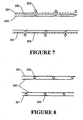
- FIG. 7 and 8 Still further configurations of a expiratory breathing conduit inc luding longitudinal reinforcement are depicted in Figures 7 and 8 . These configurations utilise longitudinal reinforcing threads running parallel to the axis of the conduit.
- the conduit includes an inner breathable polymer wall 250 with a plurality of axially extending reinforcing threads 251 running the length of said wall and spaced around the perimeter of the tube.
- the threads 251 are aligned parallel to one another and to the major axis of the conduit.
- a helical bead 253 is fused or adhered to the outside of the mesh 252.
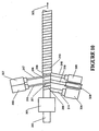
- both the inner, breathable, tube 250 and longitudinal reinforcement layer 252 are formed by helically wrapping a preformed tape or strip of the base material (breathable polymer strip 260 or mesh strip 262 respectively) on to a rotating former 270 (such as described earlier with reference to Figure 10 ).
- the strip 260 or 262 unrolls from reels 273 and 274 respectively.
- Adjacent turns of breathable polymer 260 overlap at their edges. These overlapping edges are fused by thermal welding. Thermal welding is conducted as a continuous process by a hot air welding head 275.
- Rotation and advancement of the former 270 by the rotation head 271 continually passes the seam between adjacent turns of tape 260 past the head 275.
- a freely rotatable thread laying head 276 is located over the former 270 at a position between the hot air welding head 275 and the mesh spool 274.
- the rotating head 276 carries a plurality of spools 279 holding the reinforcing threads 251.
- the head 276 is rotatable by an electric motor and drive belt 277 and 278 respectively.
- the head 276 is preferably rotated at a speed synchronized with the speed of rotation of the former 270.
- Advancement of the former 270 draws thread 280 from the spools 279 to be laid as parallel threads 251 on the outside of the breathable membrane 250.
- the tape 262 of longitudinal reinforcement is subsequently applied over the threads 251 as a helical arrangement with edges of adjacent turns overlapping to form a continuous sheath.
- a bead 263 is extruded by an extruder 281 on to the overlap between adjacent turns of the mesh tape 262 to thereby form the helical reinforcing bead 253.
- This embodiment of the invention provides a breathable exhalation limb reinforced against crushing by the helical bead and against longitudinal extension by the axial threads 251.
- the mesh sheath 252 protects the axial threads from snagging or pulling.
- the conduit includes an inner breathable polymer wall 350.
- a helical bead 353 is fused or adhered to the inner breathable wall 350.
- a plurality of reinforcing threads 251 running the length of the wall and spaced around the perimeter of the tube are aligned parallel to one another and to the major axis of the conduit.
- the threads 351 are supported on the helical bead 353, with the threads spanning the spaces between turns of the helical bead.
- the axial threads 351 may be a spun or braided fibres, drawn or extruded mono filaments or other equivalent forms.
- the breathable tube 350 is formed by helically wrapping a preformed tape or strip of breathable polymer strip 360 on to a rotating former 370.
- the strip 360 unrolls from reels 373.
- Adjacent turns ofbreathable polymer 360 overlap at their edges. These overlapping edges are fused by thermal welding.
- Thermal welding is conducted as a continuous process by a hot air welding head 375. Rotation and advancement of the former 370 continually passes the seam between adjacent turns of tape 360 past the head 375.
- a bead 363 is extruded by an extruder 381 on to the overlap between adjacent turns of the breathable tape 362 to thereby form the helical reinforcing bead 353.
- a freely rotatable threadlaying head 376 is located over the former after the bead extruder 381.
- the rotating head 376 carries a plurality of spools 379 holding the reinforcing threads 351.
- the head 376 is rotatable by an electric motor and drive belt 377 and 378 respectively.
- the head 376 is preferably rotated at a speed synchronized with the speed of rotation of the former 370. Advancement of tube along the former 370 draws thread 380 from the spools 379 to be laid as parallel threads 351 on the outside of the reinforcing bead.
- This embodiment of the invention provides a breathable exhalation limb reinforced against crushing by the helical bead and against longitudinal extension by the axial threads 351.
- the spanning threads prevent direct contact between a user and the surface of the breathable tube, reducing the risk of punctures and the like.
- conduit such as that shown in Figure 1
- other forms of the conduit may be formed by co extrusion of the breathable material (where the material is a suitable extrudable material) with a plastic material forming the remainder of the conduit wall.
- a suitable co extrusion die 9 is depicted in Figure 3 in which a pair of circumferential sections 7 of the die opening have the breathable plastic material extruded therethrough, and the remainder sections 8 of the annular extrusion opening have the non permeable plastic wall material extruded therethrough.
- the purpose of the breathable region or regions of the conduit wall is to allow diffusion of water vapour from the expiratory limb of the breathing circuit along the path thereof independent of specific drain locations. This eliminates the build up of condensation within the expiratory limb by drying the humidified gases during their flow through the expiratory limb. This furthermore reduces the humidity of the gases arriving at ancillary equipment, such as filters, ventilators and the like reducing the risk of condensation accumulation, thereby improving their operation.
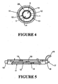
- the conduit incorporating one or more longitudinal strips of breathable membrane may further be incorporated in a coaxial breathing circuit as a passive humidification device.
- the coaxial breathing circuit may include an outer conduit 11 and an inner conduit 10.
- the inner conduit 10 carries the inspiratory flow in the space 12 there within.
- the expiratory flow is preferably carried in the space 13 between the inner conduit 10 and the outer conduit 11.
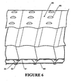
- This airflow configuration is indicated by arrows 20, 19 respectively in Figure 5 .
- the inner conduit 10 is formed having one or more longitudinal strips 2, 3 of breathable membrane in the wall 1 thereof, as has previously been described with reference to Figures 1, 2 and 3 .
- humidity in the expiratory flow space 13 may pass through the sections 2, 3 of breathable membrane to humidify the inspiratory flow in inspiratory flow space 12.
- the breathable membrane works on relative partial pressures of water vapour so, with the flows in a counter flow arrangement substantial passive humidification of the inspiratory flow can be achieved.
- FIG. 5 a circuit configured including the coaxial conduit depicted in Figure 4 is represented.
- the conduit has a patient end connector 15 and a ventilator end connector 16 having inspiratory port 17 and an expiratory port 18.
- the inspiratory 20 and expiratory 19 counter flows are indicated.
- the ventilator may not become aware of the leak in the interior conduit.
- a leak may short circuit the patient meaning that the patient will not be supplied with sufficient oxygen.
- Such a short circuit may be detected by placement of a sensor at the patient end.
- this sensor may be located in the patient end connector 15.
- a short circuit closer to the ventilator will lead to continued patient rebreathing of the air volume close to the patient. This will lead to a rise in the concentration of carbon dioxide in the conduit close to the patient which can be detected directly by a CO 2 sensor.
- Such a sensor may comprise any one of a number of such sensors as is currently commercially available.
- this re breathing may be detected by monitoring the temperature of the gases at the patient end connector 15, wherein a rise in temperature above a predetermined level indicates that rebreathing is occurring.
- a heater means such as a resistance heater wire, may be provided within either the inner or outer conduit, disposed within the gases spaces 12 or 13 or within the conduit walls themselves.
- the heater wire may also serve as a reinforcing support (helical wire 25 in Figure 4 ) within the inner conduit 10 or in the outside conduit as with coaxial conduit.
- a further breathing circuit component is catheter mounts.
- a catheter mount connects between a patient interfacing component such as a mouth piece, nasal mask or endotracheal tube and the dual limbs of a breathing circuit. Connection with the dual limbs of the breathing circuit is generally via a wye connector.
- the dual limbs of the breathing circuit each have a distinct role, one as inhalation conduit and one as exhalation conduit.
- the catheter mount serves a dual role, transporting both inhaled and exhaled gases. Accordingly, the catheter mount can have significant disadvantages.
- a volume of exhaled air remains in the catheter mount between exhalation and inhalation. Accordingly some air is re-breathed by the patient. While not unacceptable, rebreathing is not generally desirable and where significant rebreathing is likely, a boost in oxygen supply levels may be required.
- Gases inhaled by a patient are, in a well managed ventilation system, delivered in a condition having humidity near a saturation level and at close to body temperature, usually at a temperature between 33°C and 37°C. This temperature may be maintained by a heater in the inhalation conduit right up to the point where the gases enter the catheter mount. Gases exhaled by a patient are returned fully saturated and are subj ected to further cooling as they flow through the catheter mount. Accordingly, although little condensation forms on the interior walls during patient inhalation, significant condensation levels may form during patient exhalation. The condensation, or rain out, occurring inside the catheter mount is particularly deleterious due to its proximity to the patient. Mobile condensate breathed or inhaled by a patient may lead to coughing fits or other discomfort.
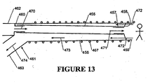
- a catheter mount is depicted in Figure 13 .
- the catheter mount incorporates the wye connector at the ventilator end.
- An internal conduit 455 extends coaxially with the outer conduit 456.
- the internal conduit 455 is supported at its patient end on a internal conduit connector 457 which is turn is supported via support struts 458 from patient end connector 459.
- the inner conduit 455 is supported at its other end on an inner conduit connector 460 which forms part of the ventilator end connector 461.
- the ventilator end inner conduit connector 460 communicates with the inspiratory conduit connector 462.
- the outer conduit 456 has at least a part of its wall being made from a breathable material.
- the outer conduit 456 is formed entirely from breathable material, and may also include lateral reinforcement (a spiral reinforcing bead 467) and longitudinal reinforcement (axially oriented threads 490) on the outside thereof.
- the spiral bead 467 is laid on the overlap between consecutive turns of the extruded tape and assists fusion of the overlap and reinforcement against crushing.
- the catheter mount according to Figure 13 has an inspiratory flow entering the catheter mount as indicated by arrow 470.
- the inspiratory flow passes through the inner conduit to exit to the patient through the patient end connector 459 as indicated by arrows 471.
- expired gases pass through connector 459 and into the space surrounding the inner conduit 455 as indicated by arrows 472.
- These gases pass along the inside of the wall of outer conduit 456 as indicated by arrows 473 and out through the expiratory tube connector 463 of ventilation connector 461 as indicated by arrow 474.
- water vapour may pass through the water vapour permeable portions of the outer conduit 456.
- the entire of outer conduit 456, apart from any reinforcing rib is breathable.
- the expired gases may experience some temperature drop as they pass through the catheter mount to the expiratory conduit connector 463, hand in hand with this temperature drop is a reduction in humidity by water vapour passing through the breathable membrane of the outer conduit. Accordingly, relative saturation of the expiratory flow is reduced and rain out is reduced.
- the catheter mount includes explicit division of the inspiratory and expiratory flows through the catheter mount - significantly reducing rebreathing. Rain out is also reduced by reducing the humidity of the expired gases even as the temperature of those gases reduces.
Landscapes
- Health & Medical Sciences (AREA)
- Engineering & Computer Science (AREA)
- Mechanical Engineering (AREA)
- Life Sciences & Earth Sciences (AREA)
- General Health & Medical Sciences (AREA)
- Pulmonology (AREA)
- Anesthesiology (AREA)
- Biomedical Technology (AREA)
- Heart & Thoracic Surgery (AREA)
- Hematology (AREA)
- Veterinary Medicine (AREA)
- Animal Behavior & Ethology (AREA)
- Emergency Medicine (AREA)
- Public Health (AREA)
- Manufacturing & Machinery (AREA)
- Materials For Medical Uses (AREA)
- Respiratory Apparatuses And Protective Means (AREA)
- Rigid Pipes And Flexible Pipes (AREA)
- Thermotherapy And Cooling Therapy Devices (AREA)
- Details Of Indoor Wiring (AREA)
- Shaping Of Tube Ends By Bending Or Straightening (AREA)
- Orthopedics, Nursing, And Contraception (AREA)
Priority Applications (2)
| Application Number | Priority Date | Filing Date | Title |
|---|---|---|---|
| EP08169317.8A EP2025359B1 (en) | 2000-05-10 | 2001-05-09 | Components for breathing circuits |
| EP10184899.2A EP2305336B1 (en) | 2000-05-10 | 2001-05-09 | Components for breathing circuits |
Applications Claiming Priority (3)
| Application Number | Priority Date | Filing Date | Title |
|---|---|---|---|
| NZ50443900 | 2000-05-10 | ||
| NZ50904100 | 2000-12-20 | ||
| EP01111359A EP1153627B1 (en) | 2000-05-10 | 2001-05-09 | Components for breathing circuits |
Related Parent Applications (1)
| Application Number | Title | Priority Date | Filing Date |
|---|---|---|---|
| EP01111359A Division EP1153627B1 (en) | 2000-05-10 | 2001-05-09 | Components for breathing circuits |
Related Child Applications (2)
| Application Number | Title | Priority Date | Filing Date |
|---|---|---|---|
| EP10184899.2A Division EP2305336B1 (en) | 2000-05-10 | 2001-05-09 | Components for breathing circuits |
| EP08169317.8A Division EP2025359B1 (en) | 2000-05-10 | 2001-05-09 | Components for breathing circuits |
Publications (3)
| Publication Number | Publication Date |
|---|---|
| EP1681071A2 EP1681071A2 (en) | 2006-07-19 |
| EP1681071A3 EP1681071A3 (en) | 2006-07-26 |
| EP1681071B1 true EP1681071B1 (en) | 2009-02-18 |
Family
ID=26652172
Family Applications (5)
| Application Number | Title | Priority Date | Filing Date |
|---|---|---|---|
| EP06005171A Expired - Lifetime EP1681071B1 (en) | 2000-05-10 | 2001-05-09 | Apparatus for producing a breathing circuit component |
| EP04017661A Expired - Lifetime EP1477200B1 (en) | 2000-05-10 | 2001-05-09 | Components for breathing circuits |
| EP01111359A Revoked EP1153627B1 (en) | 2000-05-10 | 2001-05-09 | Components for breathing circuits |
| EP10184899.2A Expired - Lifetime EP2305336B1 (en) | 2000-05-10 | 2001-05-09 | Components for breathing circuits |
| EP08169317.8A Expired - Lifetime EP2025359B1 (en) | 2000-05-10 | 2001-05-09 | Components for breathing circuits |
Family Applications After (4)
| Application Number | Title | Priority Date | Filing Date |
|---|---|---|---|
| EP04017661A Expired - Lifetime EP1477200B1 (en) | 2000-05-10 | 2001-05-09 | Components for breathing circuits |
| EP01111359A Revoked EP1153627B1 (en) | 2000-05-10 | 2001-05-09 | Components for breathing circuits |
| EP10184899.2A Expired - Lifetime EP2305336B1 (en) | 2000-05-10 | 2001-05-09 | Components for breathing circuits |
| EP08169317.8A Expired - Lifetime EP2025359B1 (en) | 2000-05-10 | 2001-05-09 | Components for breathing circuits |
Country Status (8)
| Country | Link |
|---|---|
| US (7) | US6769431B2 (enExample) |
| EP (5) | EP1681071B1 (enExample) |
| JP (9) | JP5100932B2 (enExample) |
| AU (1) | AU777186B2 (enExample) |
| BR (1) | BR0102116B1 (enExample) |
| CA (6) | CA3003007C (enExample) |
| DE (3) | DE60137733D1 (enExample) |
| SG (1) | SG100691A1 (enExample) |
Cited By (2)
| Publication number | Priority date | Publication date | Assignee | Title |
|---|---|---|---|---|
| US9802020B2 (en) | 2000-05-10 | 2017-10-31 | Fisher & Paykel Healthcare Limited | Expiratory limb for a breathing circuit |
| US10252017B2 (en) | 2000-06-21 | 2019-04-09 | Fisher & Paykel Healthcare Limited | Conduit with heating element |
Families Citing this family (155)
| Publication number | Priority date | Publication date | Assignee | Title |
|---|---|---|---|---|
| DE10007506B4 (de) * | 2000-02-18 | 2006-02-02 | Map Medizin-Technologie Gmbh | Atemgasschlauchanordnung zur Zufuhr eines Atemgases |
| AU780911C (en) * | 2000-06-21 | 2005-09-22 | Fisher & Paykel Healthcare Limited | Conduit with heated wick |
| AU2001295791A1 (en) * | 2000-11-02 | 2002-05-15 | Astrazeneca Ab | 4-substituted quinolines as antitumor agents |
| US7708013B2 (en) | 2000-12-08 | 2010-05-04 | Vapotherm, Inc. | Apparatus and method for delivering water vapor to a gas |
| EP1387700A2 (en) * | 2001-04-24 | 2004-02-11 | Medi-Physics, Inc. | Methods and devices for moisturizing hyperpolarized noble gases and pharmaceutical products thereof |
| ITMI20011073A1 (it) * | 2001-05-22 | 2002-11-22 | Mallinckrodt Holding Bv | Dispositivo per incrementare l'umidificazione del flusso d'aria respirata da un paziente |
| SE0201855D0 (sv) | 2002-06-18 | 2002-06-18 | Siemens Elema Ab | Anordning för gasdosering |
| US7291240B2 (en) * | 2002-09-09 | 2007-11-06 | Fisher & Paykel Healthcare Limited | Method of forming a conduit using a wound sacrificial layer |
| AU2003244171B2 (en) | 2002-09-09 | 2007-11-15 | Fisher & Paykel Healthcare Limited | Limb for Breathing Circuit |
| CA2685020C (en) * | 2002-09-11 | 2012-01-24 | Fisher & Paykel Healthcare Limited | Conduits and method of forming |
| US7007691B2 (en) * | 2003-05-13 | 2006-03-07 | Roger Daugherty | Apparatus and method for humidification of inspired gases |
| US7493902B2 (en) | 2003-05-30 | 2009-02-24 | Fisher & Paykel Healthcare Limited | Breathing assistance apparatus |
| AU2004203870B2 (en) * | 2003-09-17 | 2011-03-03 | Fisher & Paykel Healthcare Limited | Breathable Respiratory Mask |
| US7766050B2 (en) * | 2003-11-28 | 2010-08-03 | Fisher & Paykel Healthcare Limited | Conduit and method of forming |
| US8590032B2 (en) | 2003-12-10 | 2013-11-19 | Aventail Llc | Rule-based routing to resources through a network |
| US8661158B2 (en) * | 2003-12-10 | 2014-02-25 | Aventail Llc | Smart tunneling to resources in a network |
| US8255973B2 (en) * | 2003-12-10 | 2012-08-28 | Chris Hopen | Provisioning remote computers for accessing resources |
| JP4503322B2 (ja) * | 2004-03-22 | 2010-07-14 | 株式会社メトラン | 呼吸回路用の蛇管 |
| WO2005094663A1 (ja) * | 2004-04-02 | 2005-10-13 | Jms Co., Ltd. | 医療用器具の生体挿入用補助具 |
| US7753991B2 (en) * | 2004-07-30 | 2010-07-13 | Kertzman Systems, Inc. | Water transport method and assembly including a thin film membrane for the addition or removal of water from gases or liquids |
| WO2006044820A2 (en) * | 2004-10-14 | 2006-04-27 | Aventail Corporation | Rule-based routing to resources through a network |
| US7428902B2 (en) * | 2004-12-15 | 2008-09-30 | Newport Medical Instruments, Inc. | Humidifier system for artificial respiration |
| DE102005000922A1 (de) * | 2005-01-07 | 2006-07-20 | Seleon Gmbh | Luftbrille, Nasenstück, Y-Stück sowie Verfahren |
| US7655584B2 (en) * | 2005-07-29 | 2010-02-02 | Gore Enterprise Holdings, Inc. | Highly porous self-cohered web materials |
| US20070090290A1 (en) * | 2005-10-04 | 2007-04-26 | Rose Thomas H | Compact sample extraction and conditioning device for infrared carbon dioxide monitor for rebreather life support systems |
| KR101377900B1 (ko) | 2005-10-13 | 2014-03-27 | 신세스 게엠바하 | 약물-함침 용기 |
| GB0521349D0 (en) | 2005-10-20 | 2005-11-30 | Intersurgical Ltd | Improvements relating to ventilation tubes |
| WO2007109837A1 (en) | 2006-03-24 | 2007-10-04 | Resmed Ltd | Air delivery conduit |
| US7900626B2 (en) * | 2006-04-17 | 2011-03-08 | Daly Robert W | Method and system for controlling breathing |
| US8944056B2 (en) * | 2007-02-09 | 2015-02-03 | Resmed Limited | Humidification arrangement for a respiratory apparatus |
| FR2914192B1 (fr) * | 2007-04-02 | 2010-03-26 | Georges Boussignac | Sonde respiratoire. |
| WO2008123831A1 (en) * | 2007-04-05 | 2008-10-16 | Aerocrine Ab | Adapter, apparatus and method for exhaled breath measurements |
| US8105410B2 (en) * | 2007-07-17 | 2012-01-31 | Teleflex Medical Incorporated | Water dissipation device with capillary action |
| US8252081B2 (en) * | 2007-07-17 | 2012-08-28 | Teleflex Medical Incorporated | Water dissipation device and method |
| US8236081B2 (en) * | 2007-07-17 | 2012-08-07 | Teleflex Medical Incorporated | Permeable membrane water dissipation device |
| US8240306B2 (en) * | 2007-07-18 | 2012-08-14 | Vapotherm, Inc. | Base unit for breathing gas heating and humidification system |
| US8905023B2 (en) | 2007-10-05 | 2014-12-09 | Vapotherm, Inc. | Hyperthermic humidification system |
| KR100831077B1 (ko) * | 2007-12-14 | 2008-05-22 | (주) 아모센스 | 스트립형 면상 발열체를 이용한 동파방지 기능을 갖는파이프 및 그의 제조방법 |
| GB2455962A (en) | 2007-12-24 | 2009-07-01 | Ethicon Inc | Reinforced adhesive backing sheet, for plaster |
| CN101959480B (zh) | 2008-03-05 | 2013-06-05 | 凯希特许有限公司 | 用于将减压施加到组织部位并收集和存储组织部位的流体的敷料和方法 |
| US8967139B2 (en) * | 2008-04-29 | 2015-03-03 | Carefusion Corporation | Respiratory connector and arrangement for connecting an inspiratory tube and an expiratory tube to a medical apparatus |
| DE102008022663B4 (de) | 2008-05-07 | 2012-10-31 | Schauenburg Hose Technology Gmbh | Stretch-Schlauch |
| US9505164B2 (en) | 2009-12-30 | 2016-11-29 | Schauenburg Technology Se | Tapered helically reinforced hose and its manufacture |
| EP3974015A1 (en) | 2008-05-12 | 2022-03-30 | Fisher & Paykel Healthcare Limited | Interface |
| US9032952B2 (en) * | 2008-08-15 | 2015-05-19 | Honeywell International Inc. | Apparatus having cross conditioned breathing air |
| US9964238B2 (en) | 2009-01-15 | 2018-05-08 | Globalmed, Inc. | Stretch hose and hose production method |
| IT1400376B1 (it) * | 2009-06-23 | 2013-05-31 | N G C Medical S P A | Struttura tubolare a diametro variabile, particolarmente per uso biomedicale. |
| US20110001314A1 (en) * | 2009-07-01 | 2011-01-06 | Xerox Corporation | Security codes within scratch-off layers and method of embedding thereof |
| US8479740B2 (en) * | 2009-11-23 | 2013-07-09 | Covidien Lp | Airway devices with integral humidification |
| CA3177059A1 (en) * | 2009-12-22 | 2011-06-30 | Fisher & Paykel Healthcare Limited | Components for medical circuits |
| GB2489183B (en) * | 2009-12-23 | 2016-06-08 | Fisher & Paykel Healthcare Ltd | Improvements relating to systems for laparoscopic surgery |
| CN104888330B (zh) | 2009-12-23 | 2019-01-08 | 费雪派克医疗保健有限公司 | 加湿气体输送装置及其控制方法 |
| US12226569B2 (en) | 2009-12-23 | 2025-02-18 | Fisher & Paykel Healthcare Limted | Systems for laparoscopic surgery |
| US8814842B2 (en) | 2010-03-16 | 2014-08-26 | Kci Licensing, Inc. | Delivery-and-fluid-storage bridges for use with reduced-pressure systems |
| JP6005631B2 (ja) | 2010-05-25 | 2016-10-12 | フィッシャー アンド ペイケル ヘルスケア リミテッド | 改良型呼吸管 |
| GB2527221B (en) * | 2010-10-18 | 2016-06-22 | Fisher & Paykel | A nasal cannula, conduit and securement system |
| GB2488749A (en) | 2011-01-31 | 2012-09-12 | Systagenix Wound Man Ip Co Bv | Laminated silicone coated wound dressing |
| NZ772270A (en) * | 2011-03-15 | 2022-08-26 | ResMed Pty Ltd | Air delivery conduit |
| CN102219132B (zh) * | 2011-04-07 | 2012-07-18 | 江苏星辰星汽车附件有限公司 | 无纺布空气滤芯进气管缠绕机及其缠绕工艺 |
| CN102234042B (zh) * | 2011-04-07 | 2012-07-18 | 江苏星辰星汽车附件有限公司 | 无纺布空气滤芯进气管缠绕机 |
| GB201106491D0 (en) | 2011-04-15 | 2011-06-01 | Systagenix Wound Man Ip Co Bv | Patterened silicone coating |
| BR112013030962B1 (pt) * | 2011-06-03 | 2021-03-02 | Fisher & Paykel Healthcare Limited | tubo médico alongado e método de fabicação do tubo médico alongado |
| AU2012321401B2 (en) | 2011-10-14 | 2017-09-14 | Fisher & Paykel Healthcare Limited | Medical tubes and methods of manufacture |
| CN103987348B (zh) | 2011-12-16 | 2016-05-11 | 凯希特许有限公司 | 可释放的医用布单 |
| US10940047B2 (en) | 2011-12-16 | 2021-03-09 | Kci Licensing, Inc. | Sealing systems and methods employing a hybrid switchable drape |
| TWI590843B (zh) | 2011-12-28 | 2017-07-11 | 信迪思有限公司 | 膜及其製造方法 |
| CN105307715B (zh) | 2012-03-15 | 2017-11-17 | 费雪派克医疗保健有限公司 | 呼吸气体加湿系统 |
| AU2013240675B2 (en) * | 2012-03-30 | 2017-10-19 | Fisher & Paykel Healthcare Limited | Humidification system |
| CN107335122B (zh) | 2012-04-27 | 2022-02-18 | 费雪派克医疗保健有限公司 | 用于呼吸增湿系统的可用性特征 |
| EP4223348B1 (en) | 2012-06-25 | 2025-02-19 | Fisher & Paykel Healthcare Limited | Humidification chamber with microstructures |
| EP2708219A1 (en) | 2012-09-12 | 2014-03-19 | PARI Pharma GmbH | Opening element for opening an ampoule in an aerosol generation device and aerosol generation device comprising the opening element |
| AU2013345487B2 (en) | 2012-11-14 | 2018-08-09 | Fisher & Paykel Healthcare Limited | Zone heating for respiratory circuits |
| JP6324983B2 (ja) | 2012-11-16 | 2018-05-16 | ケーシーアイ ライセンシング インコーポレイテッド | パターン化された接着剤層を有する医療用ドレープおよびその製造方法 |
| US9795756B2 (en) | 2012-12-04 | 2017-10-24 | Mallinckrodt Hospital Products IP Limited | Cannula for minimizing dilution of dosing during nitric oxide delivery |
| DK3173116T3 (da) | 2012-12-04 | 2020-03-02 | Mallinckrodt Hospital Products Ip Ltd | Kanyle til minimering af fortynding af dosering under indgivelse af nitrogenoxid |
| ES2856688T3 (es) | 2012-12-04 | 2021-09-28 | Fisher & Paykel Healthcare Ltd | Tubos médicos y procedimientos de fabricación |
| CN104853796B (zh) * | 2012-12-17 | 2017-11-21 | 皇家飞利浦有限公司 | 旋转流体联接件 |
| GB201222770D0 (en) | 2012-12-18 | 2013-01-30 | Systagenix Wound Man Ip Co Bv | Wound dressing with adhesive margin |
| DE102013001888B4 (de) * | 2013-02-02 | 2017-07-20 | Drägerwerk AG & Co. KGaA | Vorrichtung und Verfahren zur Bereitstellung eines Atemgasstromes |
| US10092721B2 (en) * | 2013-03-13 | 2018-10-09 | Teleflex Medical Incorporated | Multi-lumen breathing circuit including a flexible printed circuit board assembly |
| GB2527226B (en) | 2013-03-14 | 2020-05-13 | Fisher & Paykel Healthcare Ltd | Medical components with microstructures for humidification and condensate management |
| CN116899065A (zh) | 2013-03-15 | 2023-10-20 | 费雪派克医疗保健有限公司 | 鼻套管组件和相关部件 |
| EP2968823B8 (en) * | 2013-03-15 | 2022-02-16 | Fisher & Paykel Healthcare Limited | Components for medical circuits |
| US10500364B2 (en) | 2013-03-15 | 2019-12-10 | Fisher & Paykel Healthcare Limited | Drying expiratory limb with tailored temperature profile and multi-lumen configuration |
| JP6456935B2 (ja) | 2013-06-21 | 2019-01-23 | デピュイ・シンセス・プロダクツ・インコーポレイテッド | フィルム及び製造方法 |
| EP3030299B1 (en) | 2013-08-09 | 2020-07-01 | Fisher & Paykel Healthcare Limited | Asymmetrical nasal delivery elements and fittings for nasal interfaces |
| EP3043850B1 (en) | 2013-09-12 | 2019-07-03 | Mayo Foundation for Medical Education and Research | Insulated endotracheal devices and systems for transpulmonary thermal transfer |
| DE112014004197T5 (de) | 2013-09-13 | 2016-06-02 | Fisher & Paykel Healthcare Limited | Verbindungen für Befeuchtungssystem |
| US10814091B2 (en) | 2013-10-24 | 2020-10-27 | Fisher & Paykel Healthcare Limited | System for delivery of respiratory gases |
| EP3062753B1 (en) | 2013-10-28 | 2018-11-21 | KCI Licensing, Inc. | Hybrid sealing tape |
| WO2015065616A1 (en) | 2013-10-30 | 2015-05-07 | Kci Licensing, Inc. | Dressing with sealing and retention intereface |
| EP3384883B1 (en) | 2013-10-30 | 2021-02-24 | 3M Innovative Properties Company | Dressing with diffrentially sized perforations |
| EP3656362A1 (en) | 2013-10-30 | 2020-05-27 | KCI Licensing, Inc. | Condensate absorbing and dissipating system related application |
| WO2015065615A1 (en) | 2013-10-30 | 2015-05-07 | Kci Licensing, Inc. | Absorbent conduit and system |
| HUE062413T2 (hu) | 2013-12-20 | 2023-10-28 | Fisher & Paykel Healthcare Ltd | Párásító rendszer csatlakozásai |
| WO2015119515A1 (en) | 2014-02-07 | 2015-08-13 | Fisher & Paykel Healthcare Limited | Respiratory humidification system |
| EP3479803B1 (en) | 2014-02-28 | 2021-03-31 | 3M Innovative Properties Company | Hybrid drape having a gel-coated perforated mesh |
| US11026844B2 (en) | 2014-03-03 | 2021-06-08 | Kci Licensing, Inc. | Low profile flexible pressure transmission conduit |
| AU2015232050B2 (en) | 2014-03-17 | 2020-01-23 | Fisher & Paykel Healthcare Limited | Medical tubes for respiratory systems |
| EP3129093B1 (en) * | 2014-04-11 | 2019-12-04 | Fisher & Paykel Healthcare Limited | Gas therapy system |
| WO2015168681A1 (en) | 2014-05-02 | 2015-11-05 | Kci Licensing, Inc. | Fluid storage devices, systems, and methods |
| EP3607988B1 (en) | 2014-06-03 | 2025-09-10 | Fisher & Paykel Healthcare Limited | A humidification chamber for a respiratory therapy apparatus |
| AU2015269359B2 (en) | 2014-06-05 | 2019-08-15 | Kci Licensing, Inc. | Dressing with fluid acquisition and distribution characteristics |
| EP3888728B1 (en) * | 2014-07-07 | 2022-10-26 | Fisher & Paykel Healthcare Limited | Medical tubes and connectors for gases delivery systems |
| DE102014215064A1 (de) * | 2014-07-31 | 2016-02-04 | Pari GmbH Spezialisten für effektive Inhalation | Vernebler |
| CN119236261A (zh) | 2014-09-03 | 2025-01-03 | 费雪派克医疗保健有限公司 | 确定性受控的增湿系统 |
| CN106999694B (zh) * | 2014-09-24 | 2020-06-09 | 费雪派克医疗保健有限公司 | 用于医疗系统的导管 |
| CN114344657A (zh) * | 2014-11-25 | 2022-04-15 | 费雪派克医疗保健有限公司 | 用于气体治疗设备的物质递送装置 |
| US10398604B2 (en) | 2014-12-17 | 2019-09-03 | Kci Licensing, Inc. | Dressing with offloading capability |
| US10596345B2 (en) | 2014-12-31 | 2020-03-24 | Vapotherm, Inc. | Systems and methods for humidity control |
| US10398871B2 (en) | 2015-03-31 | 2019-09-03 | Vapotherm, Inc. | Systems and methods for patient-proximate vapor transfer for respiratory therapy |
| US11471636B2 (en) | 2015-04-15 | 2022-10-18 | Medline Industries, Lp | Moisture removal and condensation and humidity management apparatus for a breathing circuit |
| EP3574877B1 (en) | 2015-05-08 | 2022-08-17 | 3M Innovative Properties Company | Low-acuity dressing with integral pump |
| EP3344320B1 (en) * | 2015-08-31 | 2021-03-31 | Vapotherm, Inc. | High flow therapy with built-in oxygen concentrator |
| WO2017040045A1 (en) | 2015-09-01 | 2017-03-09 | Kci Licensing, Inc. | Dressing with increased apposition force |
| CN112972856B (zh) | 2015-09-09 | 2024-12-27 | 费雪派克医疗保健有限公司 | 对呼吸回路的分区加热 |
| EP3892310B1 (en) | 2015-09-17 | 2025-10-29 | Solventum Intellectual Properties Company | Hybrid silicone and acrylic adhesive cover for use with wound treatment |
| US11504492B2 (en) * | 2015-10-08 | 2022-11-22 | ResMed Pty Ltd | Air conduit for a respiratory device |
| JP2019521723A (ja) | 2016-05-26 | 2019-08-08 | メリット・メディカル・システムズ・インコーポレイテッドMerit Medical Systems,Inc. | 拡張可能導入器アセンブリ |
| US12102768B2 (en) | 2016-06-07 | 2024-10-01 | Fisher & Paykel Healthcare Limited | Breathing circuit components for respiratory apparatus |
| AU2017297978B2 (en) | 2016-07-21 | 2022-08-25 | Fisher & Paykel Healthcare Limited | Medical tubes for breathing circuit |
| USD870269S1 (en) | 2016-09-14 | 2019-12-17 | Fisher & Paykel Healthcare Limited | Nasal cannula assembly |
| CN213642639U (zh) | 2016-10-14 | 2021-07-09 | 蒸汽热能公司 | 用于呼吸治疗单元中的流体循环的系统和蒸气转移系统 |
| WO2018075638A1 (en) * | 2016-10-19 | 2018-04-26 | Teleflex Medical Incorporated | Moisture removal and condensation and humidity management apparatus for a breathing circuit |
| FR3058842B1 (fr) * | 2016-11-16 | 2020-11-06 | Saipem Sa | Machine pour la pose simultanee et en helice de cables sur la surface externe d'un element unitaire de conduite de transport de fluides |
| EP3551978B1 (en) | 2016-12-07 | 2022-01-26 | Fisher&Paykel Healthcare Limited | Sensing arrangements for medical devices |
| EP4523724A1 (en) | 2016-12-22 | 2025-03-19 | Fisher & Paykel Healthcare Limited | Medical tubes and methods of manufacture |
| CA3053834C (en) | 2017-01-30 | 2020-09-01 | Globalmed, Inc. | Heated respiratory hose assembly |
| US10953185B2 (en) | 2017-03-31 | 2021-03-23 | Koninklijke Philips N.V. | Moisture wicking conduit and system |
| ES2979252T3 (es) * | 2017-05-26 | 2024-09-25 | Fisher & Paykel Healthcare Ltd | Tubos médicos neonatales flexibles e híbridos |
| US20180343809A1 (en) * | 2017-05-31 | 2018-12-06 | Jenna Sherman | Zippered Transplant Grow Pot |
| EP3651843B1 (en) | 2017-07-10 | 2022-12-07 | Medline Industries, LP | Moisture removal and condensation and humidity management apparatus for a breathing circuit |
| WO2019093910A1 (en) * | 2017-11-13 | 2019-05-16 | Auckland University Of Technology | Fabric and method of manufacturing |
| BR112020016864A2 (pt) | 2018-02-23 | 2020-12-22 | Fisher & Paykel Healthcare Limited | Tubos médicos para circuito respiratório |
| DK180026B1 (en) | 2018-03-12 | 2020-01-24 | Mbh-International A/S | A flexible double lumen tube and a tube coupling system for same |
| EP4458398A3 (en) | 2018-04-18 | 2025-01-01 | Fisher & Paykel Healthcare Limited | Conduits and other components with wicking properties and associated methods |
| GB201812444D0 (en) * | 2018-07-28 | 2018-09-12 | Smith Medical International Ltd | Tracheal tubes |
| US11911563B2 (en) | 2018-11-08 | 2024-02-27 | Plastiflex Group | Moisture permeable conduit for a breathing circuit |
| US20200152354A1 (en) * | 2018-11-14 | 2020-05-14 | Minnesota Wire | Integrated circuits in cable |
| EP4454692A3 (en) | 2018-11-26 | 2025-01-01 | Fisher & Paykel Healthcare Limited | Diffuser for a component of a respiratory therapy system |
| EP4631558A3 (en) | 2019-02-13 | 2025-10-29 | ResMed Pty Ltd | Textile tube for a therapy device |
| AU2020278993A1 (en) * | 2019-05-20 | 2021-11-04 | ResMed Asia Pte Ltd | Air delivery conduit |
| US12496422B2 (en) | 2019-05-20 | 2025-12-16 | ResMed Asia Pte. Ltd. | Air delivery conduit |
| CN110293662B (zh) * | 2019-06-04 | 2025-05-20 | 深圳市源泰医疗器械有限公司 | 一种呼吸管路生产装置及呼吸管路生产方法 |
| CN110755726A (zh) * | 2019-10-21 | 2020-02-07 | 斯莱达医疗用品(惠州)有限公司 | 一种同轴加热呼吸管路 |
| US20210145453A1 (en) * | 2019-11-18 | 2021-05-20 | Silk Road Medical, Inc. | Embolic protection in connection with transcarotid carotid artery revascularization |
| EP4081284A4 (en) * | 2019-12-26 | 2024-01-24 | Fisher & Paykel Healthcare Limited | RESPIRATORY THERAPY SYSTEM, INCUBATOR AND ITS MEDICAL RESPIRATORY GAS DISTRIBUTION DUCT |
| US12064562B2 (en) | 2020-03-12 | 2024-08-20 | Vapotherm, Inc. | Respiratory therapy unit with non-contact sensing and control |
| AU2021252828A1 (en) * | 2020-04-09 | 2022-12-08 | Fisher & Paykel Healthcare Limited | A respiratory conduit |
| AU2021221439A1 (en) | 2020-12-23 | 2022-07-07 | Fisher & Paykel Healthcare Limited | Tube and/or patient interface for delivery of gas |
| GB2607347B (en) * | 2021-06-04 | 2024-03-27 | Flexicare Group Ltd | A breathing assembly |
| EP4504310A1 (en) | 2022-04-08 | 2025-02-12 | Fisher & Paykel Healthcare Limited | Medical gases conduit |
| WO2024130313A1 (en) * | 2022-12-21 | 2024-06-27 | Colin Dunlop | An apparatus for delivering fluid to a small patient |
| CN117398558B (zh) * | 2023-11-24 | 2024-04-05 | 河北悦之恒医疗器械有限公司 | 一种湿化呼吸机 |
| CN118807066A (zh) * | 2024-07-30 | 2024-10-22 | 中国人民解放军总医院第一医学中心 | 一种脱机状态下气管插管加湿的装置 |
Family Cites Families (180)
| Publication number | Priority date | Publication date | Assignee | Title |
|---|---|---|---|---|
| US373559A (en) * | 1887-11-22 | Fredeeick j | ||
| DE28036C (de) | 1884-02-12 | 1884-07-23 | J. WOLFF in Grofs-Gerau, Gr. Hessen | Freiluftathmer |
| GB587163A (en) * | 1944-02-04 | 1947-04-16 | Wingfoot Corp | Improvements relating to tubes or packages and methods of making the same |
| US2868199A (en) | 1955-05-20 | 1959-01-13 | Charles H Hudson | Cannula |
| GB975819A (enExample) | 1960-04-01 | |||
| NL128859C (enExample) | 1960-09-19 | |||
| US3303105A (en) | 1963-03-25 | 1967-02-07 | Gen Electric | Diffusion of water vapor through slicone rubber |
| US3296343A (en) * | 1963-03-27 | 1967-01-03 | Phillips Petroleum Co | Method and apparatus for producing blown thermoplastic tubing |
| US3245206A (en) | 1963-08-02 | 1966-04-12 | Engelhard Ind Inc | Diffusion purification apparatus |
| US3292346A (en) | 1964-03-06 | 1966-12-20 | Renard P Adams | Gas drying apparatus |
| US3367850A (en) | 1964-12-07 | 1968-02-06 | Exxon Research Engineering Co | Method and apparatus for determining moisture content of hydrocarbon fluids |
| US3292646A (en) * | 1965-03-26 | 1966-12-20 | David W Pollock | Bottle cleaning device |
| US3307330A (en) | 1965-04-30 | 1967-03-07 | Du Pont | Diffusion process and apparatus |
| US3434471A (en) | 1966-04-06 | 1969-03-25 | Smithkline Corp | Therapeutic intermittent positive pressure respirator |
| US3513844A (en) | 1968-04-30 | 1970-05-26 | Metro Hospital Supply Co Inc | Adjustable nonrestrictive nasal cannula |
| US3639970A (en) * | 1969-10-02 | 1972-02-08 | Phillips Petroleum Co | Method and apparatus for forming plastic-lined metal conduit |
| US3682171A (en) | 1971-03-31 | 1972-08-08 | Baxter Laboratories Inc | Nasal cannula |
| US3754552A (en) | 1971-06-08 | 1973-08-28 | Sandoz Ag | Flexible nasal cannula |
| US3735558A (en) | 1971-06-29 | 1973-05-29 | Perma Pure Process Inc | Process for separating fluids and apparatus |
| US3891556A (en) | 1971-11-15 | 1975-06-24 | Oxy Metal Ind Intra Inc | Multi-layer braided tubular membrane reinforcement |
| US3735559A (en) | 1972-02-02 | 1973-05-29 | Gen Electric | Sulfonated polyxylylene oxide as a permselective membrane for water vapor transport |
| US3856051A (en) * | 1972-02-28 | 1974-12-24 | J Bain | Flexible tube device |
| US3803810A (en) | 1972-05-01 | 1974-04-16 | Pall Corp | Liquid-gas separator and filter |
| US3910808A (en) | 1972-08-30 | 1975-10-07 | Steward Plastics | Apparatus for making helically wound plastic tubing |
| DE2321553C2 (de) | 1972-08-30 | 1983-10-20 | Steward Plastics, Inc., Santa Ana, Calif. | Vorrichtung zum Herstellen eines wendelförmig gewickelten flexiblen Rohres |
| US3871373A (en) * | 1972-10-30 | 1975-03-18 | Richard R Jackson | Humidifying gas |
| US3912795A (en) * | 1972-10-30 | 1975-10-14 | Richard R Jackson | Humidifying gas |
| FR2226608A1 (en) * | 1973-04-20 | 1974-11-15 | Automation Ind Inc | Reinforced flexible pipe from helical strip - has wire embedded in matrix within helical seam |
| US3895630A (en) | 1973-06-04 | 1975-07-22 | Del Mar Eng Lab | Respiratory gas analyzer including a carbon dioxide and respiratory quotient computer |
| US3889717A (en) | 1973-12-14 | 1975-06-17 | Deere & Co | Reinforced flexible tube |
| US4007737A (en) | 1974-01-28 | 1977-02-15 | Paluch Bernard R | Anesthesia breathing system |
| US3895530A (en) * | 1974-05-16 | 1975-07-22 | Elster Ag | Tubular swirl flow meter |
| CH581474A5 (enExample) * | 1974-06-27 | 1976-11-15 | Draegerwerk Ag | |
| US3963856A (en) | 1974-11-25 | 1976-06-15 | Steward Plastics, Inc. | Flexible, corrugated, plastic tubing having conductive helical bead |
| DE2529050C2 (de) | 1975-06-30 | 1983-01-05 | Drägerwerk AG, 2400 Lübeck | Feuchtigkeitsaustauscher in Geräten für Atmung und Narkose |
| DE2711236C2 (de) * | 1976-05-14 | 1982-09-23 | Shiro Osaka Ibaragi Kanao | Verfahren und Vorrichtung zum kontinuierlichen Herstellen eines Rohres |
| US4327775A (en) | 1977-05-09 | 1982-05-04 | The Gates Rubber Company | Formable hose with a reformable insert |
| US4204562A (en) | 1978-04-27 | 1980-05-27 | Kelly Walter F | Two-ply duct core |
| US4207457A (en) | 1978-06-29 | 1980-06-10 | The Kanthal Corporation | Porcupine wire coil electric resistance fluid heater |
| US4262704A (en) * | 1978-08-30 | 1981-04-21 | Caterpillar Tractor Co. | High pressure reinforced hydraulic hose |
| US4216769A (en) | 1978-09-29 | 1980-08-12 | Grimes Jerry L | Bi-flow nasal cup |
| US4265239A (en) | 1978-11-27 | 1981-05-05 | Fischer Jr Charles M | Gas scavenging exhaust system |
| US4265235A (en) * | 1979-05-11 | 1981-05-05 | Fukunaga Atsuo F | Anesthetic system |
| US4456034A (en) | 1980-02-19 | 1984-06-26 | Bixby Guy T | Formable hose |
| US4337800A (en) * | 1980-07-07 | 1982-07-06 | Steward Plastics, Inc. | Two piece extruded hose |
| US4336796A (en) * | 1980-08-04 | 1982-06-29 | Andrews E Trent | Adjustable lower extremity splint with single point suspension |
| US4327718A (en) | 1980-09-18 | 1982-05-04 | Becton, Dickinson And Company | Continuously draining trap for removal of condensate from a patient breathing circuit |
| US4653542A (en) | 1980-10-02 | 1987-03-31 | The Kendall Company | Medical tubing and connector |
| US4336798A (en) | 1980-10-06 | 1982-06-29 | Anthony V. Beran | Medical corrugated respiratory tube |
| US4462397A (en) * | 1981-04-03 | 1984-07-31 | Terumo Corporation | Breathing circuit |
| JPS57190571A (en) * | 1981-05-20 | 1982-11-24 | Terumo Corp | Bellow pipe with reduced extensibility for breathing apparatus |
| US4463755A (en) * | 1981-05-18 | 1984-08-07 | Terumo Corporation | Breathing circuit |
| SE428345C (sv) * | 1981-12-23 | 1989-04-17 | Gambro Engstrom Ab | Foerfarande vid maetning och anordning foer maetning av koncentrationen av en eller flera givna komponenter i en av en patient in- och eller utandad andningsgas |
| US4420016A (en) | 1982-01-07 | 1983-12-13 | Nichols Ralph A | Kink-preventing spine for aquarium air hoses |
| US4409283A (en) | 1982-01-25 | 1983-10-11 | Boyle Jr Donald E | Formable viscid caulking member and method of making same |
| US4406283A (en) | 1982-02-04 | 1983-09-27 | Phillip Bir | Oxygen cannulae for continuous administration of oxygen, and its associated mounting structure and method for mounting same onto the head of a patient |
| GB2139110B (en) | 1982-12-27 | 1987-05-20 | Gen Electric | Water vapor exchange system |
| JPS59119304U (ja) | 1983-01-29 | 1984-08-11 | 株式会社エルマ | 液体中の溶存ガス脱気装置 |
| US4682010A (en) | 1983-03-07 | 1987-07-21 | Safeway Products, Inc. | In-line electric heater for an aerosol delivery system |
| US4490575A (en) | 1983-05-26 | 1984-12-25 | Automation Industries, Inc. | Flexible hose with external sheathed electrical conductor |
| FR2564733B1 (fr) | 1984-05-22 | 1987-05-29 | Centre Nat Rech Scient | Appareil portable de lutte contre l'hypothermie chez l'homme, par inhalation d'air chaud et humidifie |
| US4773410A (en) | 1984-10-09 | 1988-09-27 | Transpirator Technologies, Inc. | Method and apparatus for the treatment of the respiratory track with vapor-phase water |
| JPH0310464Y2 (enExample) | 1984-10-22 | 1991-03-14 | ||
| SU1342514A1 (ru) | 1984-11-26 | 1987-10-07 | Всесоюзный научно-исследовательский институт горноспасательного дела | Влаготеплообменное устройство дыхательного аппарата на химически св занном кислороде |
| WO1986004660A1 (fr) | 1985-02-04 | 1986-08-14 | Witzenmann Gmbh Metallschlauch-Fabrik Pforzheim | Tuyau flexible avec ondes annulaires paralleles les unes aux autres et support axial |
| DE3650465T2 (de) | 1985-02-09 | 1996-09-12 | Asahi Chemical Ind | Durchlässige Polymer-Membran für die Gastrocknung |
| GB2173274B (en) | 1985-04-04 | 1989-02-01 | Boc Group Plc | Improvements in inhalation apparatus |
| AU581986B2 (en) | 1985-05-22 | 1989-03-09 | Fisher & Paykel Healthcare Limited | Improvements in or relating to methods of and/or apparatus for humidifying gases |
| US4722334A (en) | 1985-07-16 | 1988-02-02 | Transpirator Technologies, Inc. | Method and apparatus for pulmonary and cardiovascular conditioning of racehorses and competition animals |
| US4698890A (en) | 1985-10-31 | 1987-10-13 | The Gates Rubber Company | Method for making a formable and curve shape retentive hose |
| JPS62236724A (ja) | 1986-04-08 | 1987-10-16 | Taigaasu Polymer Kk | 可撓管の製造方法 |
| US4705543A (en) * | 1986-09-19 | 1987-11-10 | Perma Pure Products, Inc. | Fluid drying tube |
| US4808201A (en) * | 1986-09-19 | 1989-02-28 | Perma Pure Products, Inc. | Connector construction for fluid drying tube |
| US4753233A (en) | 1987-02-10 | 1988-06-28 | Advantage Medical | Nasal cannula |
| SE459155B (sv) | 1987-04-14 | 1989-06-12 | Siemens Elema Ab | Foerfarande och anording foer aateranvaendning av anestesimedel |
| WO1989002447A1 (en) | 1987-09-10 | 1989-03-23 | Hewlett-Packard Company | Water-vapour permeable material |
| WO1989003523A1 (en) * | 1987-10-09 | 1989-04-20 | Cascadia Technology Corporation | Gas analyzer |
| JPH01194927A (ja) | 1988-01-27 | 1989-08-04 | Japan Gore Tex Inc | 水蒸気選択透過膜 |
| US5335656A (en) | 1988-04-15 | 1994-08-09 | Salter Laboratories | Method and apparatus for inhalation of treating gas and sampling of exhaled gas for quantitative analysis |
| US5233996A (en) * | 1988-05-20 | 1993-08-10 | Boc Health Care, Inc. | Patient interfacing system and method to prevent water contamination |
| NZ226784A (en) * | 1988-09-29 | 1992-10-28 | Fisher & Paykel | Gas humidifier with microporous wall |
| US4915105A (en) | 1988-10-28 | 1990-04-10 | Lee Tien Chu | Miniature respiratory apparatus |
| FR2638361B1 (fr) | 1988-10-28 | 1991-01-11 | Diffusion Tech Francaise Sarl | Embout narinaire adaptable sur tous appareils a usage medical du type nebuliseurs et autres |
| US4967744A (en) * | 1988-11-03 | 1990-11-06 | Airoflex Medical, Inc. | Flexible breathing circuit |
| US4915104A (en) | 1989-01-09 | 1990-04-10 | Cynthia L. Vogt | Nasal oxygen tube support and method |
| US4995384A (en) | 1989-10-30 | 1991-02-26 | Keeling James L | Neck support for nasal cannula |
| JP2889294B2 (ja) * | 1989-11-29 | 1999-05-10 | 古河電気工業株式会社 | カテーテル用チューブ |
| WO1991008012A1 (en) | 1989-12-01 | 1991-06-13 | Borody Thomas J | Oxygenating oral medical appliance |
| US5230119A (en) | 1990-04-13 | 1993-07-27 | M. J. Woods, Inc. | Multilayer laminated pad |
| US5042500A (en) * | 1990-06-18 | 1991-08-27 | Medical Graphics Corporation | Drying sample line |
| JP3057831B2 (ja) | 1991-08-27 | 2000-07-04 | ダイキン工業株式会社 | 加湿器及び熱交換器 |
| SE502780C2 (sv) | 1991-09-25 | 1996-01-08 | Siemens Elema Ab | Avfuktningsanordning |
| US5284160A (en) * | 1991-11-13 | 1994-02-08 | Dryden Gale E | Consolidated anesthesia circuit |
| DE9200567U1 (de) | 1992-01-18 | 1992-07-02 | HEW - Kabel Heinz Eilentropp KG, 5272 Wipperfürth | Beheizbarer Beatmungsschlauch |
| US5165395A (en) | 1992-02-14 | 1992-11-24 | Ricci Mark R | Ultra-violet germicidal mask system |
| US5186035A (en) | 1992-02-18 | 1993-02-16 | General Electric Company | Tube loading sleeve for pilger mill |
| GB9215154D0 (en) * | 1992-07-16 | 1992-08-26 | Smiths Industries Plc | Tubing and humidification systems |
| US5915378A (en) | 1993-01-29 | 1999-06-29 | Aradigm Corporation | Creating an aerosolized formulation of insulin |
| US5389430A (en) | 1993-02-05 | 1995-02-14 | Th. Goldschmidt Ag | Textiles coated with waterproof, moisture vapor permeable polymers |
| JPH06254164A (ja) * | 1993-03-02 | 1994-09-13 | Terumo Corp | 医療用チューブの製造方法 |
| IT229819Y1 (it) | 1993-04-19 | 1999-02-05 | Dar Spa | Struttura di tubo spiralato per apparecchiature di ventilazione artificiale di pazienti |
| US5392770A (en) | 1993-06-29 | 1995-02-28 | Clawson; Burrell E. | Tubing circuit systems for humidified respiratory gas |
| US5411474A (en) | 1993-07-14 | 1995-05-02 | Douglas E. Ott | Method and apparatus for conditioning insufflation gas for laparoscopic surgery |
| CA2168756C (en) | 1993-08-06 | 2004-12-07 | Joachim Brandenburger | A method and apparatus of producing a tubular lining hose |
| SE501042C2 (sv) | 1993-09-17 | 1994-10-24 | Gibeck Respiration Ab | Anordning vid fukt-värmeväxlare |
| US5427291A (en) | 1993-09-21 | 1995-06-27 | Smith; David S. | Ski carrier and method employing same |
| US5595174A (en) | 1994-02-28 | 1997-01-21 | Gwaltney; Max R. | Nasal adaptor, mask, and method |
| JPH08109984A (ja) | 1994-03-15 | 1996-04-30 | Fisher & Paykel Ltd | 加湿ガスを送るための導管及びその製造工程 |
| DE4410921C2 (de) * | 1994-03-29 | 1996-12-19 | Atochem Elf Deutschland | Polymermischung und deren Verwendung |
| JPH07275637A (ja) | 1994-04-08 | 1995-10-24 | Asahi Glass Co Ltd | 除湿方法 |
| US5513634A (en) | 1994-05-06 | 1996-05-07 | Chek-Med Systems, Inc. | Combination integral bite block airway and nasal cannula |
| US5454061A (en) | 1994-05-27 | 1995-09-26 | Steward Plastics, Inc. | Apparatus and method for making flexible tubing with helically wound heating conductor |
| US5848223A (en) | 1994-05-27 | 1998-12-08 | Steward Plastics, Inc. | Double-walled flexible tubing product with helical support bead and heating conductor and apparatus and method for making |
| US5653228A (en) | 1994-10-25 | 1997-08-05 | Byrd; Timothy N. | Medical tube holding device and associated securing strap |
| FR2727738A1 (fr) | 1994-12-05 | 1996-06-07 | Coflexip | Conduite tubulaire flexible comportant une nappe d'armure agrafee |
| US5709762A (en) * | 1995-01-27 | 1998-01-20 | Karen F. Hurwitz And Daniel N. Lundeen, P.C. | Method for making reinforced flexible ducting |
| GB9503012D0 (en) | 1995-02-16 | 1995-04-05 | Smiths Industries Plc | Humidifier systems |
| US5630409A (en) | 1995-03-22 | 1997-05-20 | Bono; Michael | Nebulizer and inhalation device containing same |
| US5586551A (en) | 1995-07-17 | 1996-12-24 | Hilliard; Kenneth R. | Oxygen mask with nebulizer |
| US5603991A (en) | 1995-09-29 | 1997-02-18 | Target Therapeutics, Inc. | Method for coating catheter lumens |
| WO1997018001A1 (en) | 1995-11-13 | 1997-05-22 | Fisher & Paykel Limited | Heated respiratory conduit |
| US5829428A (en) | 1996-05-29 | 1998-11-03 | Alliance Pharmaceutical Corp. | Methods and apparatus for reducing the loss of respiratory promoters |
| DE19621541C1 (de) | 1996-05-29 | 1997-04-10 | Draegerwerk Ag | Beatmungsanfeuchter |
| FI104312B1 (fi) | 1996-06-27 | 1999-12-31 | Instrumentarium Oy | Sovitelma intuboidun potilaan hengityskaasun käsittelemiseksi |
| JP3748466B2 (ja) | 1996-08-23 | 2006-02-22 | 株式会社メトラン | 加湿調整ユニット及び加湿調整ユニットの製造方法 |
| US5704344A (en) | 1996-09-06 | 1998-01-06 | Cole; Jeanne M. | Device for relieving anxiety in respiratory patients |
| US5722391A (en) | 1996-11-12 | 1998-03-03 | Par Medical, Inc. | Anesthesia tube assembly |
| US5778872A (en) * | 1996-11-18 | 1998-07-14 | Medlis, Inc. | Artificial ventilation system and methods of controlling carbon dioxide rebreathing |
| JP3304049B2 (ja) | 1997-02-17 | 2002-07-22 | タイガースポリマー株式会社 | 可撓性ホース |
| JP3547109B2 (ja) * | 1997-03-13 | 2004-07-28 | 大陽東洋酸素株式会社 | 医療用ガスの加湿方法及びその供給管 |
| CA2621113C (en) | 1997-06-17 | 2011-10-11 | Fisher & Paykel Healthcare Limited | Respiratory humidification system |
| FR2766547B1 (fr) * | 1997-07-24 | 1999-09-17 | Gessil | Conduit flexible, par exemple tuyau a usage medical ou chirurgical |
| US6119694A (en) | 1997-07-24 | 2000-09-19 | Respironics Georgia, Inc. | Nasal mask and headgear |
| US6216732B1 (en) | 1997-10-30 | 2001-04-17 | Rpm Industries, Inc. | Portable fluid transfer conduit |
| US6039696A (en) * | 1997-10-31 | 2000-03-21 | Medcare Medical Group, Inc. | Method and apparatus for sensing humidity in a patient with an artificial airway |
| NL1007699C2 (nl) | 1997-12-04 | 1999-06-09 | Medisize Bv | Beademingssysteem. |
| GB9726820D0 (en) | 1997-12-20 | 1998-02-18 | Smiths Industries Plc | Tubes |
| US6167883B1 (en) | 1998-01-23 | 2001-01-02 | Respiratory Support Products, Inc. | Medical air hose internal flow heater |
| IL123122A0 (en) | 1998-01-29 | 1998-09-24 | Oridion Medical Ltd | Oral/nasal cannula |
| JP3451336B2 (ja) | 1998-05-13 | 2003-09-29 | 真佐子 中村 | 土木用排水材 |
| JP2000024113A (ja) * | 1998-07-09 | 2000-01-25 | Tonokura Ika Kogyo Kk | 医療用チューブ装置 |
| US6363930B1 (en) | 1998-07-10 | 2002-04-02 | Enternet Medical, Inc. | Apparatus for providing heat/moisture to respiratory gases |
| JP2000024111A (ja) | 1998-07-13 | 2000-01-25 | Senko Medical Instr Mfg Co Ltd | 呼吸回路 |
| JP3354104B2 (ja) * | 1998-08-04 | 2002-12-09 | ソニー株式会社 | 陰極線管の絶縁方法 |
| US6105576A (en) | 1998-10-14 | 2000-08-22 | Enternet Medical, Inc. | Apparatus for treating respiratory gases including liquid trap |
| US6637434B2 (en) | 1998-10-30 | 2003-10-28 | Linda J. Noble | Nasal gas delivery system and method for use thereof |
| US6595215B2 (en) | 2000-03-13 | 2003-07-22 | Innomed Technologies, Inc. | Ventilation interface for sleep apnea therapy |
| AU4910900A (en) | 1999-05-28 | 2000-12-18 | Euromedico Ltd. | Gas-supplying device |
| DE10014792A1 (de) | 1999-06-17 | 2001-01-18 | Daimler Chrysler Ag | Vorrichtung und Verfahren zur Gastrocknung |
| AU775872B2 (en) | 1999-08-10 | 2004-08-19 | Fisher & Paykel Healthcare Limited | A ventilation system and/or breathing tube |
| US6536436B1 (en) | 1999-10-26 | 2003-03-25 | Mcglothen Roberta | Strap for nasal cannula |
| EP1237614B1 (en) | 1999-12-10 | 2005-10-19 | Vapotherm, Inc. | Apparatus for respiratory tract therapy |
| US6412481B1 (en) | 1999-12-23 | 2002-07-02 | Robert Bienvenu | Sealed backpressure attachment device for nebulizer |
| US6523538B1 (en) * | 2000-01-05 | 2003-02-25 | Instrumentarium Corp. | Breathing circuit having improved water vapor removal |
| JP2001284433A (ja) | 2000-01-28 | 2001-10-12 | Sony Corp | 基板移載装置及び基板移載方法 |
| US6516798B1 (en) | 2000-03-07 | 2003-02-11 | Timothy A. Davies | Method of breathing tracheally |
| US6539937B1 (en) | 2000-04-12 | 2003-04-01 | Instrumentarium Corp. | Method of maximizing the mechanical displacement of a piezoelectric nebulizer apparatus |
| BR0102116B1 (pt) | 2000-05-10 | 2010-09-21 | componente para um membro de circuito de respiração. | |
| US6367510B1 (en) | 2000-06-02 | 2002-04-09 | Eric Carlson | Tubing product having a helical support bead with lumen and method |
| AU780911C (en) | 2000-06-21 | 2005-09-22 | Fisher & Paykel Healthcare Limited | Conduit with heated wick |
| US7559324B2 (en) | 2000-06-21 | 2009-07-14 | Fisher & Paykel Healthcare Limited | Conduit with heated wick |
| ITMI20011073A1 (it) | 2001-05-22 | 2002-11-22 | Mallinckrodt Holding Bv | Dispositivo per incrementare l'umidificazione del flusso d'aria respirata da un paziente |
| JP2003111774A (ja) | 2001-07-31 | 2003-04-15 | Senko Medical Instr Mfg Co Ltd | 気腹ガス用加温加湿器及び気腹装置 |
| CA2370995C (en) | 2001-09-13 | 2010-08-17 | Fisher & Paykel Healthcare Limited | Breathing assistance apparatus |
| US6779522B2 (en) * | 2001-10-16 | 2004-08-24 | Perma Pure, Inc. | Method and apparatus for treating breathing gases |
| US6769432B1 (en) | 2002-04-10 | 2004-08-03 | Hamilton Medical, Inc. | Method and apparatus for non-abrasive cushioning seal of assisted breathing devices |
| AU2003244171B2 (en) | 2002-09-09 | 2007-11-15 | Fisher & Paykel Healthcare Limited | Limb for Breathing Circuit |
| US7291240B2 (en) | 2002-09-09 | 2007-11-06 | Fisher & Paykel Healthcare Limited | Method of forming a conduit using a wound sacrificial layer |
| US7493902B2 (en) | 2003-05-30 | 2009-02-24 | Fisher & Paykel Healthcare Limited | Breathing assistance apparatus |
| US7856982B2 (en) | 2004-03-11 | 2010-12-28 | Ric Investments, Llc | Patient interface device |
| WO2006120683A2 (en) | 2005-05-10 | 2006-11-16 | Oridion Medical Ltd. | Fluid drying mechanism |
| US20070235100A1 (en) | 2005-10-12 | 2007-10-11 | Arrowhead Products Corporation | Double walled, self-insulating, lightweight duct |
| US7658208B2 (en) | 2006-09-25 | 2010-02-09 | Veyance Technologies, Inc. | Kink, crush, and burst resistant flexible hose construction |
| US20090025724A1 (en) | 2007-07-16 | 2009-01-29 | Herron Jr Roy Howard | System for removal of water from a hose and the hygroscopic hose utilized |
| JP5052378B2 (ja) | 2008-03-25 | 2012-10-17 | オリンパスメディカルシステムズ株式会社 | 顕微鏡 |
| US9067035B2 (en) | 2009-03-03 | 2015-06-30 | Oridion Medical (1987) Ltd. | Drying substances, preparation and use thereof |
| CA3177059A1 (en) * | 2009-12-22 | 2011-06-30 | Fisher & Paykel Healthcare Limited | Components for medical circuits |
| WO2012077052A1 (en) | 2010-12-08 | 2012-06-14 | Koninklijke Philips Electronics N.V. | Proximal humidifier comprising hydrophobic membrane |
| ES2856688T3 (es) | 2012-12-04 | 2021-09-28 | Fisher & Paykel Healthcare Ltd | Tubos médicos y procedimientos de fabricación |
| US10500364B2 (en) | 2013-03-15 | 2019-12-10 | Fisher & Paykel Healthcare Limited | Drying expiratory limb with tailored temperature profile and multi-lumen configuration |
-
2001
- 2001-05-07 BR BRPI0102116-8A patent/BR0102116B1/pt not_active IP Right Cessation
- 2001-05-08 CA CA3003007A patent/CA3003007C/en not_active Expired - Lifetime
- 2001-05-08 CA CA2346628A patent/CA2346628C/en not_active Expired - Lifetime
- 2001-05-08 US US09/850,797 patent/US6769431B2/en not_active Expired - Lifetime
- 2001-05-08 CA CA2697142A patent/CA2697142C/en not_active Expired - Lifetime
- 2001-05-08 CA CA2833707A patent/CA2833707C/en not_active Expired - Lifetime
- 2001-05-08 CA CA2980806A patent/CA2980806C/en not_active Expired - Lifetime
- 2001-05-08 CA CA2934358A patent/CA2934358C/en not_active Expired - Lifetime
- 2001-05-09 EP EP06005171A patent/EP1681071B1/en not_active Expired - Lifetime
- 2001-05-09 EP EP04017661A patent/EP1477200B1/en not_active Expired - Lifetime
- 2001-05-09 EP EP01111359A patent/EP1153627B1/en not_active Revoked
- 2001-05-09 EP EP10184899.2A patent/EP2305336B1/en not_active Expired - Lifetime
- 2001-05-09 DE DE60137733T patent/DE60137733D1/de not_active Expired - Lifetime
- 2001-05-09 SG SG200102699A patent/SG100691A1/en unknown
- 2001-05-09 AU AU43823/01A patent/AU777186B2/en not_active Expired
- 2001-05-09 EP EP08169317.8A patent/EP2025359B1/en not_active Expired - Lifetime
- 2001-05-09 DE DE60131315T patent/DE60131315T2/de not_active Expired - Lifetime
- 2001-05-09 DE DE60123679T patent/DE60123679T2/de not_active Expired - Lifetime
- 2001-05-10 JP JP2001140405A patent/JP5100932B2/ja not_active Expired - Lifetime
-
2003
- 2003-07-18 US US10/622,755 patent/US7140366B2/en not_active Expired - Lifetime
-
2006
- 2006-03-09 US US11/371,389 patent/US20060162726A1/en not_active Abandoned
- 2006-04-19 JP JP2006115614A patent/JP4699268B2/ja not_active Expired - Fee Related
-
2008
- 2008-12-04 US US12/328,200 patent/US9802020B2/en not_active Expired - Fee Related
-
2010
- 2010-07-20 JP JP2010163144A patent/JP5411078B2/ja not_active Expired - Lifetime
-
2012
- 2012-11-15 JP JP2012251582A patent/JP5564093B2/ja not_active Expired - Lifetime
-
2014
- 2014-03-05 JP JP2014043100A patent/JP6482177B2/ja not_active Expired - Lifetime
-
2015
- 2015-07-10 JP JP2015138521A patent/JP6341891B2/ja not_active Expired - Lifetime
-
2016
- 2016-12-21 JP JP2016248163A patent/JP2017051816A/ja not_active Withdrawn
-
2017
- 2017-06-26 US US15/633,557 patent/US20170296769A1/en not_active Abandoned
- 2017-11-17 US US15/816,965 patent/US10159814B2/en not_active Expired - Fee Related
-
2018
- 2018-03-19 JP JP2018051411A patent/JP2018089495A/ja active Pending
- 2018-09-11 JP JP2018169865A patent/JP2019018028A/ja active Pending
- 2018-12-06 US US16/211,909 patent/US10286174B2/en not_active Expired - Fee Related
Cited By (4)
| Publication number | Priority date | Publication date | Assignee | Title |
|---|---|---|---|---|
| US9802020B2 (en) | 2000-05-10 | 2017-10-31 | Fisher & Paykel Healthcare Limited | Expiratory limb for a breathing circuit |
| US10159814B2 (en) | 2000-05-10 | 2018-12-25 | Fisher & Paykel Healthcare Limited | Components for breathing circuits |
| US10286174B2 (en) | 2000-05-10 | 2019-05-14 | Fisher & Paykel Healthcare Limited | Components for breathing circuits |
| US10252017B2 (en) | 2000-06-21 | 2019-04-09 | Fisher & Paykel Healthcare Limited | Conduit with heating element |
Also Published As
Similar Documents
| Publication | Publication Date | Title |
|---|---|---|
| US10286174B2 (en) | Components for breathing circuits | |
| AU2004202878B2 (en) | Components For Breathing Circuits | |
| HK1090312B (en) | Apparatus for producing a breathing circuit component | |
| HK1126433A (en) | Components for breathing circuits | |
| HK1126433B (en) | Components for breathing circuits | |
| HK1037551B (en) | Components for breathing circuits | |
| HK1156265A (en) | Components for breathing circuits |
Legal Events
| Date | Code | Title | Description |
|---|---|---|---|
| PUAI | Public reference made under article 153(3) epc to a published international application that has entered the european phase |
Free format text: ORIGINAL CODE: 0009012 |
|
| PUAL | Search report despatched |
Free format text: ORIGINAL CODE: 0009013 |
|
| 17P | Request for examination filed |
Effective date: 20060314 |
|
| AC | Divisional application: reference to earlier application |
Ref document number: 1153627 Country of ref document: EP Kind code of ref document: P |
|
| AK | Designated contracting states |
Kind code of ref document: A2 Designated state(s): DE FR GB IT |
|
| AK | Designated contracting states |
Kind code of ref document: A3 Designated state(s): DE FR GB IT |
|
| REG | Reference to a national code |
Ref country code: HK Ref legal event code: DE Ref document number: 1090312 Country of ref document: HK |
|
| AKX | Designation fees paid |
Designated state(s): DE FR GB IT |
|
| 17Q | First examination report despatched |
Effective date: 20070515 |
|
| GRAP | Despatch of communication of intention to grant a patent |
Free format text: ORIGINAL CODE: EPIDOSNIGR1 |
|
| GRAS | Grant fee paid |
Free format text: ORIGINAL CODE: EPIDOSNIGR3 |
|
| GRAA | (expected) grant |
Free format text: ORIGINAL CODE: 0009210 |
|
| AC | Divisional application: reference to earlier application |
Ref document number: 1153627 Country of ref document: EP Kind code of ref document: P |
|
| AK | Designated contracting states |
Kind code of ref document: B1 Designated state(s): DE FR GB IT |
|
| REG | Reference to a national code |
Ref country code: GB Ref legal event code: FG4D |
|
| REF | Corresponds to: |
Ref document number: 60137733 Country of ref document: DE Date of ref document: 20090402 Kind code of ref document: P |
|
| REG | Reference to a national code |
Ref country code: HK Ref legal event code: GR Ref document number: 1090312 Country of ref document: HK |
|
| PLBE | No opposition filed within time limit |
Free format text: ORIGINAL CODE: 0009261 |
|
| STAA | Information on the status of an ep patent application or granted ep patent |
Free format text: STATUS: NO OPPOSITION FILED WITHIN TIME LIMIT |
|
| 26N | No opposition filed |
Effective date: 20091119 |
|
| REG | Reference to a national code |
Ref country code: FR Ref legal event code: PLFP Year of fee payment: 16 |
|
| REG | Reference to a national code |
Ref country code: FR Ref legal event code: PLFP Year of fee payment: 17 |
|
| REG | Reference to a national code |
Ref country code: FR Ref legal event code: PLFP Year of fee payment: 18 |
|
| PGFP | Annual fee paid to national office [announced via postgrant information from national office to epo] |
Ref country code: FR Payment date: 20200528 Year of fee payment: 20 |
|
| PGFP | Annual fee paid to national office [announced via postgrant information from national office to epo] |
Ref country code: GB Payment date: 20200528 Year of fee payment: 20 Ref country code: IT Payment date: 20200522 Year of fee payment: 20 |
|
| PGFP | Annual fee paid to national office [announced via postgrant information from national office to epo] |
Ref country code: DE Payment date: 20200728 Year of fee payment: 20 |
|
| REG | Reference to a national code |
Ref country code: DE Ref legal event code: R071 Ref document number: 60137733 Country of ref document: DE |
|
| REG | Reference to a national code |
Ref country code: GB Ref legal event code: PE20 Expiry date: 20210508 |
|
| PG25 | Lapsed in a contracting state [announced via postgrant information from national office to epo] |
Ref country code: GB Free format text: LAPSE BECAUSE OF EXPIRATION OF PROTECTION Effective date: 20210508 |