EP1680818B1 - Ensemble diode électroluminescente comprenant une platine dissipant la chaleur - Google Patents
Ensemble diode électroluminescente comprenant une platine dissipant la chaleur Download PDFInfo
- Publication number
- EP1680818B1 EP1680818B1 EP04818383.4A EP04818383A EP1680818B1 EP 1680818 B1 EP1680818 B1 EP 1680818B1 EP 04818383 A EP04818383 A EP 04818383A EP 1680818 B1 EP1680818 B1 EP 1680818B1
- Authority
- EP
- European Patent Office
- Prior art keywords
- light
- emitting diode
- diode chip
- arrangement according
- plate
- Prior art date
- Legal status (The legal status is an assumption and is not a legal conclusion. Google has not performed a legal analysis and makes no representation as to the accuracy of the status listed.)
- Active
Links
- 229910052751 metal Inorganic materials 0.000 claims description 16
- 239000002184 metal Substances 0.000 claims description 16
- 239000000463 material Substances 0.000 claims description 15
- 239000000758 substrate Substances 0.000 claims description 12
- 238000006243 chemical reaction Methods 0.000 claims description 9
- 239000000853 adhesive Substances 0.000 claims description 5
- 230000001070 adhesive effect Effects 0.000 claims description 5
- 230000017525 heat dissipation Effects 0.000 claims description 5
- 239000002313 adhesive film Substances 0.000 claims description 3
- 229910017083 AlN Inorganic materials 0.000 claims 1
- PIGFYZPCRLYGLF-UHFFFAOYSA-N Aluminum nitride Chemical compound [Al]#N PIGFYZPCRLYGLF-UHFFFAOYSA-N 0.000 claims 1
- 239000010410 layer Substances 0.000 description 26
- 239000004020 conductor Substances 0.000 description 7
- 230000000694 effects Effects 0.000 description 7
- 239000000126 substance Substances 0.000 description 6
- 239000000919 ceramic Substances 0.000 description 4
- PMHQVHHXPFUNSP-UHFFFAOYSA-M copper(1+);methylsulfanylmethane;bromide Chemical compound Br[Cu].CSC PMHQVHHXPFUNSP-UHFFFAOYSA-M 0.000 description 3
- 239000012790 adhesive layer Substances 0.000 description 2
- 230000004888 barrier function Effects 0.000 description 2
- 239000003822 epoxy resin Substances 0.000 description 2
- 238000009413 insulation Methods 0.000 description 2
- 230000004048 modification Effects 0.000 description 2
- 238000012986 modification Methods 0.000 description 2
- 229920000647 polyepoxide Polymers 0.000 description 2
- 239000004065 semiconductor Substances 0.000 description 2
- RYGMFSIKBFXOCR-UHFFFAOYSA-N Copper Chemical compound [Cu] RYGMFSIKBFXOCR-UHFFFAOYSA-N 0.000 description 1
- 239000004593 Epoxy Substances 0.000 description 1
- OAICVXFJPJFONN-UHFFFAOYSA-N Phosphorus Chemical compound [P] OAICVXFJPJFONN-UHFFFAOYSA-N 0.000 description 1
- 239000002390 adhesive tape Substances 0.000 description 1
- 229910052782 aluminium Inorganic materials 0.000 description 1
- XAGFODPZIPBFFR-UHFFFAOYSA-N aluminium Chemical compound [Al] XAGFODPZIPBFFR-UHFFFAOYSA-N 0.000 description 1
- 238000003491 array Methods 0.000 description 1
- 239000010953 base metal Substances 0.000 description 1
- 239000000969 carrier Substances 0.000 description 1
- 239000012876 carrier material Substances 0.000 description 1
- 229910010293 ceramic material Inorganic materials 0.000 description 1
- 239000012141 concentrate Substances 0.000 description 1
- 238000001816 cooling Methods 0.000 description 1
- 229910052802 copper Inorganic materials 0.000 description 1
- 239000010949 copper Substances 0.000 description 1
- 230000006378 damage Effects 0.000 description 1
- 230000001419 dependent effect Effects 0.000 description 1
- 230000007613 environmental effect Effects 0.000 description 1
- 239000000945 filler Substances 0.000 description 1
- 238000010438 heat treatment Methods 0.000 description 1
- 238000009434 installation Methods 0.000 description 1
- 238000002955 isolation Methods 0.000 description 1
- 150000002739 metals Chemical class 0.000 description 1
- 238000000034 method Methods 0.000 description 1
- 230000007935 neutral effect Effects 0.000 description 1
- 239000011368 organic material Substances 0.000 description 1
- 229910052594 sapphire Inorganic materials 0.000 description 1
- 239000010980 sapphire Substances 0.000 description 1
Images

Classifications
-
- H—ELECTRICITY
- H01—ELECTRIC ELEMENTS
- H01L—SEMICONDUCTOR DEVICES NOT COVERED BY CLASS H10
- H01L33/00—Semiconductor devices having potential barriers specially adapted for light emission; Processes or apparatus specially adapted for the manufacture or treatment thereof or of parts thereof; Details thereof
- H01L33/48—Semiconductor devices having potential barriers specially adapted for light emission; Processes or apparatus specially adapted for the manufacture or treatment thereof or of parts thereof; Details thereof characterised by the semiconductor body packages
- H01L33/64—Heat extraction or cooling elements
-
- H—ELECTRICITY
- H01—ELECTRIC ELEMENTS
- H01L—SEMICONDUCTOR DEVICES NOT COVERED BY CLASS H10
- H01L2224/00—Indexing scheme for arrangements for connecting or disconnecting semiconductor or solid-state bodies and methods related thereto as covered by H01L24/00
- H01L2224/01—Means for bonding being attached to, or being formed on, the surface to be connected, e.g. chip-to-package, die-attach, "first-level" interconnects; Manufacturing methods related thereto
- H01L2224/10—Bump connectors; Manufacturing methods related thereto
- H01L2224/15—Structure, shape, material or disposition of the bump connectors after the connecting process
- H01L2224/16—Structure, shape, material or disposition of the bump connectors after the connecting process of an individual bump connector
- H01L2224/161—Disposition
- H01L2224/16135—Disposition the bump connector connecting between different semiconductor or solid-state bodies, i.e. chip-to-chip
- H01L2224/16145—Disposition the bump connector connecting between different semiconductor or solid-state bodies, i.e. chip-to-chip the bodies being stacked
-
- H—ELECTRICITY
- H01—ELECTRIC ELEMENTS
- H01L—SEMICONDUCTOR DEVICES NOT COVERED BY CLASS H10
- H01L2224/00—Indexing scheme for arrangements for connecting or disconnecting semiconductor or solid-state bodies and methods related thereto as covered by H01L24/00
- H01L2224/01—Means for bonding being attached to, or being formed on, the surface to be connected, e.g. chip-to-package, die-attach, "first-level" interconnects; Manufacturing methods related thereto
- H01L2224/42—Wire connectors; Manufacturing methods related thereto
- H01L2224/47—Structure, shape, material or disposition of the wire connectors after the connecting process
- H01L2224/48—Structure, shape, material or disposition of the wire connectors after the connecting process of an individual wire connector
- H01L2224/4805—Shape
- H01L2224/4809—Loop shape
- H01L2224/48091—Arched
-
- H—ELECTRICITY
- H01—ELECTRIC ELEMENTS
- H01L—SEMICONDUCTOR DEVICES NOT COVERED BY CLASS H10
- H01L2224/00—Indexing scheme for arrangements for connecting or disconnecting semiconductor or solid-state bodies and methods related thereto as covered by H01L24/00
- H01L2224/73—Means for bonding being of different types provided for in two or more of groups H01L2224/10, H01L2224/18, H01L2224/26, H01L2224/34, H01L2224/42, H01L2224/50, H01L2224/63, H01L2224/71
- H01L2224/732—Location after the connecting process
- H01L2224/73251—Location after the connecting process on different surfaces
- H01L2224/73265—Layer and wire connectors
-
- H—ELECTRICITY
- H01—ELECTRIC ELEMENTS
- H01L—SEMICONDUCTOR DEVICES NOT COVERED BY CLASS H10
- H01L2224/00—Indexing scheme for arrangements for connecting or disconnecting semiconductor or solid-state bodies and methods related thereto as covered by H01L24/00
- H01L2224/80—Methods for connecting semiconductor or other solid state bodies using means for bonding being attached to, or being formed on, the surface to be connected
- H01L2224/85—Methods for connecting semiconductor or other solid state bodies using means for bonding being attached to, or being formed on, the surface to be connected using a wire connector
- H01L2224/85909—Post-treatment of the connector or wire bonding area
- H01L2224/8592—Applying permanent coating, e.g. protective coating
-
- H—ELECTRICITY
- H01—ELECTRIC ELEMENTS
- H01L—SEMICONDUCTOR DEVICES NOT COVERED BY CLASS H10
- H01L33/00—Semiconductor devices having potential barriers specially adapted for light emission; Processes or apparatus specially adapted for the manufacture or treatment thereof or of parts thereof; Details thereof
- H01L33/48—Semiconductor devices having potential barriers specially adapted for light emission; Processes or apparatus specially adapted for the manufacture or treatment thereof or of parts thereof; Details thereof characterised by the semiconductor body packages
- H01L33/64—Heat extraction or cooling elements
- H01L33/642—Heat extraction or cooling elements characterized by the shape
-
- H—ELECTRICITY
- H05—ELECTRIC TECHNIQUES NOT OTHERWISE PROVIDED FOR
- H05K—PRINTED CIRCUITS; CASINGS OR CONSTRUCTIONAL DETAILS OF ELECTRIC APPARATUS; MANUFACTURE OF ASSEMBLAGES OF ELECTRICAL COMPONENTS
- H05K1/00—Printed circuits
- H05K1/02—Details
- H05K1/0201—Thermal arrangements, e.g. for cooling, heating or preventing overheating
- H05K1/0203—Cooling of mounted components
-
- H—ELECTRICITY
- H05—ELECTRIC TECHNIQUES NOT OTHERWISE PROVIDED FOR
- H05K—PRINTED CIRCUITS; CASINGS OR CONSTRUCTIONAL DETAILS OF ELECTRIC APPARATUS; MANUFACTURE OF ASSEMBLAGES OF ELECTRICAL COMPONENTS
- H05K1/00—Printed circuits
- H05K1/18—Printed circuits structurally associated with non-printed electric components
- H05K1/182—Printed circuits structurally associated with non-printed electric components associated with components mounted in the printed circuit board, e.g. insert mounted components [IMC]
Definitions
- the present invention relates to light-emitting diode arrays in which LED dice (light-emitting diode chips) are arranged on a heat dissipating board.
- the invention is to the effect that the heat loss can be dissipated by improving the thermal resistance of the device more efficient. If according to the invention, the heat can be dissipated well by low thermal resistance, it can be transferred without high temperature gradient on the LED carrier.
- the thermal resistance is expressed in K (Kelvin) / W (Watt).
- PCBs printed circuit boards
- ceramic boards are known, which, although better thermal properties compared to the printed circuit boards based on epoxy resin, but are very brittle and fragile, which more than limits their use as a carrier material.
- metal core boards are also used in the prior art. These typically have a sandwich-type structure based on the metal core base, an insulation layer and a conductor track.
- US Pat. No. 6,498,355 B1 describes a light emitting diode array comprising a light emitting diode chip and a multi-layer metal circuit board.
- the base is a core of the board and serves for heat dissipation.
- the light-emitting diode arrangement has an electrically insulating and thermally conductive connecting layer between an emitting surface of the light-emitting diode chip and the circuit board.
- an intermediate carrier is arranged between the light-emitting diode chip and the board.
- the invention is based on the recognition that the prior art in the use of metal core boards, the dissipation of heat loss from the LED, which is placed on the conductor, is limited by the underlying insulating layer, which in turn limits the power density of the LED.
- a light-emitting diode arrangement with at least one light-emitting diode chip is provided. Furthermore, a multilayer board comprising a base of a thermally highly conductive material, such as metal is provided, the base is a core of the board and is used for heat dissipation and wherein an electrically insulating and thermally conductive bonding layer between the emitting surface of the LED chip and the board is arranged.
- the light-emitting diode chip is arranged such that the substrate of the light-emitting diodes faces away from the printed circuit board, wherein an intermediate carrier separate from these parts is arranged between the light-emitting diode chip and the base of the printed circuit board, with which the light-emitting diode chip is electrically contacted the intermediate carrier is formed by an aluminum nitride substrate, wherein the electrically insulating connecting layer is an adhesive film, which is arranged directly on the base and on which the intermediate carrier is arranged directly Contrary to the prior art, the thermal insulating (epoxy) layer is eliminated, the heat transfer from the LED chip to the heat dissipating base material of the board is significantly improved.
- An insulating adhesive layer which is realized by an adhesive film, is particularly advantageous if a light-emitting diode chip is used, whose base-facing surface is electrically conductive. In this case, separate electrical isolation must be provided between the chip and the base to prevent short circuits and ESD failures.
- the light-emitting diode chip can be accommodated in a recess of the board.
- the light-emitting diode chip can be sunk in such a way that its upper side does not protrude beyond the contour of the board and, for example, terminates flush with the upper side of the board.
- the recess into which the LED chip is set can be formed in the heat-dissipating base of the board.
- the depression can have further functions.
- the recess may have a reflector effect, wherein advantageously the walls of the recess are at least partially bevelled.
- the light-emitting diode arrangement is formed by the "face-down" mounting technique, in which the light-emitting diode chip is arranged such that the substrate of the light-emitting diodes faces away from the circuit board.
- the light-emitting diode chip can be arranged on the intermediate carrier by means of a conductive adhesive.
- the side of the intermediate carrier facing the printed circuit board can be electrically insulating, wherein the region of the intermediate carrier facing the light-emitting diode chip can have conductive regions, such as conductor tracks.
- At least the region of the at least one light-emitting diode chip may be covered by a lens, such as a Fresnel lens.
- the area between the board and the lens may be at least partially filled with a color conversion substance.
- the color conversion substance can therefore be arranged next to and / or above the light-emitting diode chip.
- the recess can be filled laterally from the chip with a color conversion substance to obtain an LED with a substantially white light characteristic.
- the light-emitting diode chip can be contacted by means of wires from a printed circuit board, wherein this printed circuit board is laterally applied by the light-emitting diode chip sandwiched by means of an intermediate insulating layer on the board.
- an LED should be placed as directly as possible on the heat dissipating base, for example, a metal core board.
- this step must overcome the problem that LED dies are often conductive across the LED substrate or its base-facing surface, which can result in a short circuit to the printed circuit board base material, which is often undesirable and particularly so regarding the wiring options of the LEDs no design freedom.
- an LED die is placed on the base material (for example metal) 5 of a metal-core board 17 by means of a thermally conductive but electrically insulating layer 2.
- the metal core board 17 has, in addition to this base metal core 5, an overlying electrically insulating layer 4 and an electrically conductive layer with conductor tracks 3, wherein preferably the electrically insulating layer 4 and the interconnect layer 3 have congruent recesses 16, in which the LED die 1 is inserted.
- the electrical contacting of the LED dies occurs in this arrangement, in which the substrate of the LED dies facing the printed circuit board 1), laterally from the printed conductors 3 by means of wires 11 on the upper side of the LED dice.
- the region of the LED dies 1 and the recess 16 can be covered by a substantially dome-shaped lens 6, which concentrates the light emitted by the LED die 1.
- the electrical contacting of in FIG. 1 The LED arrangement shown can be made via plug contacts 7, etc. provided outside the area covered by the lens 6.
- a material with high thermal conductivity is generally used, so that preferably metals, such as aluminum or copper can be used.
- the electrically insulating but thermally conductive connection layer 2 can be, for example, a non-conductive substrate layer of the LEDs (for example, green LEDs often use sapphire) or else a thermally conductive and electrically insulating adhesive.
- the electrically insulating but thermally conductive connection layer 2 may therefore be part of the LED dies 1, the multilayer board 17 and / or a separate layer thereof.
- the separate Layer is particularly necessary when the LED Dies 1 are arranged such that their the multilayer board 17 facing surface is electrically conductive.
- red LEDs for example, which consist of two diode layers arranged one above the other, one of the two layers of the multilayer board 17 always faces, which is why a separate insulation is required to avoid short circuits and ESD failures.
- the insulating layer 4 of the metal-core board 17 can be made, for example, of organic materials or thin ceramics (the latter are, for example, slurried onto the metal carrier 5, or the metal carrier is coated with a baked-on ceramic tape.
- the base 5 of the board 17 also has a recess 18 into which the LED die 1 is inserted. Since the walls of this recess 18 are chamfered in the metallic base material 5 of the board 17, these metallic walls of the recess 18, an advantageous mirror or. Unfold reflector effect. Incidentally, another shape of the walls and / or the bottom of the recess is conceivable, the mirror or reflector effect.
- the base material 5 of the multilayer board 17 serves not only for fastening and heat dissipation of the LED Dies 1, but also for targeted light steering in the direction away from the board.
- This light control by the reflector effect of the recess 18 in the base material 5 of the board 17 is preferably matched with the effect of the lens 6.
- LEDs can be achieved by means of color conversion means.
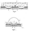
- Such LEDs are often referred to in the art as “phosphor converter LEDs” or “Lumineszenzkonversions LEDs”. How out FIG. 3 can be seen, such a color conversion substance 13 may be applied directly to the LED, be filled in the space between the lens 6 and LED die 1 or according to the in FIG. 3 illustrated example, the recesses 12, 18 arranged to be filling, so that the filler is the top of the wiring layer 3 of the board 17 flush.
- the dome-shaped lens is replaced by a flat Fresnel lens 9.
- a flat Fresnel lens 9 can cover several LED dies 1.
- a control electronics 8 for the LEDs may be provided.
- FIG. 1 to FIG. 4 all LED Dies, which are "face up", that is, with the LED substrate down (in the direction of the base material 5 of the board 17) are arranged.
- FIG. 5 now shows the reverse case according to the invention, that is according to FIG. 5 the LED die 1 "face down” is arranged so that the substrate of the LEDs facing away from the metal core 5 of the board 17.
- the LED die 1 is arranged on an intermediate carrier 10 by means of a conductive adhesive 20.
- the conductive adhesive 20 has, for example, a thickness of less than 10 ⁇ m and a thermal conductivity of more than 2 W / mK.
- the electrical contact of the LED Dice 1 of FIG. 5 thus takes place via wires 11 which are contacted with the intermediate carrier 10.
- Such "face down” mounted LED dies usually have higher efficiencies compared to "face up” mounted LED dies.
- the intermediate carrier 10 is made of a ceramic material, for example, and has conductor tracks on its upper side, while the underside is optionally electrically insulated from the metal core 5 of the circuit board 17 by a further insulating layer 19. Again, however, the insulating layer 19 is so equipped that it is thermally well conductive.
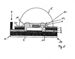
- FIG. 6 a further embodiment according to the invention is shown, in which the LED Die 1 in turn “face down” is arranged on an intermediate carrier 10 in order to achieve the improved light output and thus higher brightness in this arrangement.
- This intermediate carrier is preferably an AlN (aluminum nitride) ceramic carrier substrate, which has excellent heat-conducting properties and at the same time has an electrically insulating effect.
- the advantage in the use of this additional intermediate carrier 10 is that a higher ESD (electrostatic discharge) strength is achieved and the metkallkernplatine remains electrically neutral.
- the LED 1 is now surrounded with a color conversion substance 13 in order to convert the light into a desired (mixed) color.
- the upper side of the electrically conductive layer 3 is further covered with an additional adhesive layer 21, the task of which is to fix the lens 6.
- an additional adhesive layer 21 the task of which is to fix the lens 6.
- a double-sided adhesive tape 22 is provided, which allows easy attachment of the entire light-emitting diode array.
Landscapes
- Engineering & Computer Science (AREA)
- Microelectronics & Electronic Packaging (AREA)
- Manufacturing & Machinery (AREA)
- Computer Hardware Design (AREA)
- Power Engineering (AREA)
- Led Device Packages (AREA)
- Arrangement Of Elements, Cooling, Sealing, Or The Like Of Lighting Devices (AREA)
- Cooling Or The Like Of Semiconductors Or Solid State Devices (AREA)
Claims (14)
- Ensemble diode électroluminescente, présentant :- au moins une puce de diode électroluminescente (1),- une platine multicouche (17) avec une base (5) en un matériau bon conducteur de chaleur, en particulier en métal, dans lequel la base (5) est un noyau de la platine (17) et sert à la dissipation de chaleur, et- une couche de liaison (2), électriquement isolante et thermiquement conductrice, entre la surface d'émission de la puce de diode électroluminescente (1) et la platine, dans lequel la puce de diode électroluminescente (1) est disposée de telle sorte que le substrat des diodes électroluminescentes est opposé à la platine (17),
dans lequel un support intermédiaire (10) est disposé entre la puce de diode électroluminescente (1) et la base (5) de la platine (17), le support intermédiaire (10) étant distinct de ces parties et la puce de diode électroluminescente (1) étant en contact électrique avec le support intermédiaire (10),
caractérisé en ce que
le support intermédiaire (10) est constitué par un substrat de nitrure d'aluminium, et la couche de liaison (2) électriquement isolée est un film adhésif, qui est disposé directement sur la base (5) et sur lequel le support intermédiaire (10) est directement disposé. - Ensemble selon l'une des revendications précédentes,
dans lequel
la puce de diode électroluminescente (1) est logée dans un creux (16) de la platine (17). - Ensemble selon l'une des revendications précédentes,
caractérisé en ce que
la puce de diode électroluminescente (1) est disposée dans la région d'un creux (12) dans le matériau de base (5) de la platine (17). - Ensemble selon la revendication 2 ou 3,
caractérisé en ce que
la puce de diode électroluminescente (1) ne fait pas saillie au-delà du contour de la platine (5). - Ensemble selon l'une des revendications 2 à 4,
caractérisé en ce que
la puce de diode électroluminescente (1) se termine de manière plane de niveau avec le côté supérieur de la platine (17). - Ensemble selon l'une des revendications 2 à 4,
caractérisé en ce que
le creux (12, 16) a la fonction d'un réflecteur. - Ensemble selon l'une des revendications 2 à 6,
caractérisé en ce que
les parois du creux (12, 16) sont au moins partiellement chanfreinées. - Ensemble selon l'une des revendications précédentes,
caractérisé en ce que
la puce de diode électroluminescente (1) est agencée sur le support intermédiaire (10) au moyen d'une colle conductrice (20). - Ensemble selon l'une des revendications précédentes,
caractérisé en ce que
le côté du support intermédiaire (10) faisant face à la platine (17) est isolé électriquement. - Ensemble selon la revendication 9,
caractérisé en ce que
la région du support intermédiaire (10) faisant face à la puce de diode électroluminescente (1) présente des régions conductrices. - Ensemble selon l'une des revendications précédentes,
caractérisé en ce que
au moins la région de la puce de diode électroluminescente (1) est recouverte par une lentille (6), en particulier une lentille de Fresnel (9). - Ensemble selon la revendication 11,
caractérisé en ce que
la région entre la platine (17) et la lentille (6, 9) est remplie au moins en partie avec une substance de conversion de couleur (13). - Ensemble selon la revendication 12,
caractérisé en ce que
la substance de conversion de couleur (13) est disposée au-dessus et à côté de la puce de diode électroluminescente (1). - Ensemble selon l'une des revendications précédentes,
caractérisé en ce que
la puce de diode électroluminescente (1) est mise en contact au moyen de fils (11) à partir d'un circuit imprimé (3), lequel est disposé en sandwich sur la platine (17) au moyen d'une couche intermédiaire d'isolation (4).
Applications Claiming Priority (2)
| Application Number | Priority Date | Filing Date | Title |
|---|---|---|---|
| DE10351934.3A DE10351934B4 (de) | 2003-11-07 | 2003-11-07 | Leuchtdioden-Anordnung mit wärmeabführender Platine |
| PCT/EP2004/012438 WO2005048358A1 (fr) | 2003-11-07 | 2004-11-03 | Ensemble diode electroluminescente comprenant une platine dissipant la chaleur |
Publications (2)
| Publication Number | Publication Date |
|---|---|
| EP1680818A1 EP1680818A1 (fr) | 2006-07-19 |
| EP1680818B1 true EP1680818B1 (fr) | 2014-05-21 |
Family
ID=34559429
Family Applications (1)
| Application Number | Title | Priority Date | Filing Date |
|---|---|---|---|
| EP04818383.4A Active EP1680818B1 (fr) | 2003-11-07 | 2004-11-03 | Ensemble diode électroluminescente comprenant une platine dissipant la chaleur |
Country Status (8)
| Country | Link |
|---|---|
| US (1) | US8766283B2 (fr) |
| EP (1) | EP1680818B1 (fr) |
| JP (1) | JP2007510297A (fr) |
| KR (1) | KR101116723B1 (fr) |
| CN (1) | CN100442552C (fr) |
| AU (1) | AU2004310132B2 (fr) |
| DE (1) | DE10351934B4 (fr) |
| WO (1) | WO2005048358A1 (fr) |
Families Citing this family (36)
| Publication number | Priority date | Publication date | Assignee | Title |
|---|---|---|---|---|
| DE102005049858B3 (de) * | 2005-10-18 | 2007-02-01 | Benq Mobile Gmbh & Co. Ohg | Multilayer-Leiterplatte für Kommunikationsendgeräte |
| JP5066333B2 (ja) * | 2005-11-02 | 2012-11-07 | シチズン電子株式会社 | Led発光装置。 |
| JP2007208061A (ja) * | 2006-02-02 | 2007-08-16 | Sharp Corp | 半導体発光素子,その製造方法,半導体発光素子アセンブリ |
| JP2007234886A (ja) * | 2006-03-01 | 2007-09-13 | Compal Communications Inc | 散熱構成を有する電子素子アセンブリ |
| TWI306674B (en) * | 2006-04-28 | 2009-02-21 | Delta Electronics Inc | Light emitting apparatus |
| TWI314366B (en) * | 2006-04-28 | 2009-09-01 | Delta Electronics Inc | Light emitting apparatus |
| CN101079460B (zh) * | 2006-05-23 | 2010-05-12 | 台达电子工业股份有限公司 | 发光装置 |
| DE102006043882A1 (de) | 2006-09-19 | 2008-03-27 | Giesecke & Devrient Gmbh | Sensor zur Untersuchung eines Wertdokuments und Verfahren zur Herstellung des Sensors |
| DE102006059702A1 (de) * | 2006-09-29 | 2008-04-03 | Osram Opto Semiconductors Gmbh | Optoelektronisches Bauelement |
| KR20080057881A (ko) * | 2006-12-21 | 2008-06-25 | 엘지전자 주식회사 | 인쇄회로기판, 이를 포함하는 발광 장치 및 그 제조 방법 |
| DE102008021618A1 (de) * | 2007-11-28 | 2009-06-04 | Osram Opto Semiconductors Gmbh | Chipanordnung, Anschlussanordnung, LED sowie Verfahren zur Herstellung einer Chipanordnung |
| CN101546754A (zh) * | 2008-03-26 | 2009-09-30 | 富准精密工业(深圳)有限公司 | 发光二极管模组 |
| JP2009239036A (ja) * | 2008-03-27 | 2009-10-15 | Hitachi Aic Inc | Led基板 |
| US20100078661A1 (en) * | 2008-09-26 | 2010-04-01 | Wei Shi | Machined surface led assembly |
| US9252336B2 (en) | 2008-09-26 | 2016-02-02 | Bridgelux, Inc. | Multi-cup LED assembly |
| TW201017922A (en) * | 2008-10-23 | 2010-05-01 | Everlight Electronics Co Ltd | Light emitting diode package |
| KR101064793B1 (ko) * | 2009-06-08 | 2011-09-14 | 박종진 | 방열엘이디보드 |
| JP2011066028A (ja) * | 2009-09-15 | 2011-03-31 | Hitachi Ltd | 多波長光源装置 |
| WO2011034259A1 (fr) * | 2009-09-17 | 2011-03-24 | 포인트엔지니어링 | Substrat d'élément optique, dispositif d'élément optique et procédé de fabrication de ceux-ci |
| DE102009060781A1 (de) * | 2009-12-22 | 2011-06-30 | Automotive Lighting Reutlingen GmbH, 72762 | Lichtmodul für eine Beleuchtungseinrichtung eines Kraftfahrzeugs sowie Beleuchtungseinrichtung mit einem solchen Lichtmodul |
| DE102011003608A1 (de) * | 2010-08-20 | 2012-02-23 | Tridonic Gmbh & Co. Kg | Gehäustes LED-Modul |
| CN102052594A (zh) * | 2010-12-20 | 2011-05-11 | 惠州志能达光电科技有限公司 | 一种高散热led光源模组及其制作方法 |
| TWI464929B (zh) * | 2011-03-16 | 2014-12-11 | Lextar Electronics Corp | 提昇散熱效率之光源模組及其嵌入式封裝結構 |
| US8603858B2 (en) * | 2011-07-12 | 2013-12-10 | Infineon Technologies Ag | Method for manufacturing a semiconductor package |
| KR101321001B1 (ko) * | 2011-12-26 | 2013-10-22 | 주식회사 루멘스 | 발광소자 패키지 및 발광소자 패키지 제조방법 |
| JP2013201256A (ja) * | 2012-03-23 | 2013-10-03 | Toshiba Lighting & Technology Corp | 配線基板装置、発光モジュール、照明装置および配線基板装置の製造方法 |
| FI125565B (en) * | 2012-09-08 | 2015-11-30 | Lumichip Ltd | LED chip-on-board component and lighting module |
| KR101974348B1 (ko) * | 2012-09-12 | 2019-05-02 | 삼성전자주식회사 | 발광소자 패키지 및 그 제조방법 |
| WO2015183827A2 (fr) * | 2014-05-27 | 2015-12-03 | Cogenra Solar, Inc. | Module à cellules solaires en chevauchement |
| US8927398B2 (en) * | 2013-01-04 | 2015-01-06 | International Business Machines Corporation | Group III nitrides on nanopatterned substrates |
| CN103152976B (zh) * | 2013-03-25 | 2016-06-15 | 乐健科技(珠海)有限公司 | 用于led安装的陶瓷基印刷电路板 |
| KR101431588B1 (ko) | 2013-04-09 | 2014-08-29 | 주식회사 굿엘이디 | 고효율 cob led 패키지 |
| CN104009028B (zh) * | 2014-05-26 | 2017-06-06 | 上海信耀电子有限公司 | 陶瓷基板和散热衬底的大功率led集成封装方法及结构 |
| US11942561B2 (en) | 2014-05-27 | 2024-03-26 | Maxeon Solar Pte. Ltd. | Shingled solar cell module |
| CN106206905B (zh) * | 2015-04-29 | 2019-01-15 | 光宝光电(常州)有限公司 | 发光二极管封装结构 |
| CN105805694A (zh) * | 2016-04-07 | 2016-07-27 | 深圳市华星光电技术有限公司 | 一种量子点光源及量子点背光模组 |
Family Cites Families (29)
| Publication number | Priority date | Publication date | Assignee | Title |
|---|---|---|---|---|
| DE3587772T2 (de) * | 1984-11-12 | 1994-07-07 | Takiron Co | Punktmatrix-Leuchtanzeige. |
| JPH0680841B2 (ja) * | 1986-04-07 | 1994-10-12 | 株式会社小糸製作所 | 照明装置 |
| US5529852A (en) * | 1987-01-26 | 1996-06-25 | Sumitomo Electric Industries, Ltd. | Aluminum nitride sintered body having a metallized coating layer on its surface |
| KR880014692A (ko) * | 1987-05-30 | 1988-12-24 | 강진구 | 반사경이 부착된 반도체 발광장치 |
| JPH01313969A (ja) * | 1988-06-13 | 1989-12-19 | Hitachi Ltd | 半導体装置 |
| US5512131A (en) * | 1993-10-04 | 1996-04-30 | President And Fellows Of Harvard College | Formation of microstamped patterns on surfaces and derivative articles |
| JP3165779B2 (ja) * | 1995-07-18 | 2001-05-14 | 株式会社トクヤマ | サブマウント |
| US6608332B2 (en) * | 1996-07-29 | 2003-08-19 | Nichia Kagaku Kogyo Kabushiki Kaisha | Light emitting device and display |
| US6441943B1 (en) * | 1997-04-02 | 2002-08-27 | Gentex Corporation | Indicators and illuminators using a semiconductor radiation emitter package |
| JPH11112028A (ja) * | 1997-10-02 | 1999-04-23 | Matsushita Electron Corp | 半導体発光装置 |
| DE29804489U1 (de) * | 1998-03-13 | 1998-05-20 | Reitter & Schefenacker Gmbh | Außenrückblickspiegel für Fahrzeuge, vorzugsweise für Kraftfahrzeuge |
| US6335548B1 (en) * | 1999-03-15 | 2002-01-01 | Gentex Corporation | Semiconductor radiation emitter package |
| JP2002532893A (ja) * | 1998-12-17 | 2002-10-02 | コーニンクレッカ フィリップス エレクトロニクス エヌ ヴィ | 光エンジン |
| CN1135638C (zh) * | 1999-10-14 | 2004-01-21 | 凌士忠 | 发光二极管装置 |
| TW465123B (en) * | 2000-02-02 | 2001-11-21 | Ind Tech Res Inst | High power white light LED |
| US6428189B1 (en) * | 2000-03-31 | 2002-08-06 | Relume Corporation | L.E.D. thermal management |
| JP4432275B2 (ja) | 2000-07-13 | 2010-03-17 | パナソニック電工株式会社 | 光源装置 |
| JP2002042525A (ja) * | 2000-07-26 | 2002-02-08 | Toyoda Gosei Co Ltd | 面状光源 |
| DE60137972D1 (de) * | 2001-04-12 | 2009-04-23 | Matsushita Electric Works Ltd | Lichtquellenbauelement mit led und verfahren zu seiner herstellung |
| ATE551731T1 (de) | 2001-04-23 | 2012-04-15 | Panasonic Corp | Lichtemittierende einrichtung mit einem leuchtdioden-chip |
| JP2002319705A (ja) * | 2001-04-23 | 2002-10-31 | Matsushita Electric Works Ltd | Led装置 |
| JP2003008069A (ja) * | 2001-06-19 | 2003-01-10 | Sanyo Electric Co Ltd | 発光装置 |
| JP4045781B2 (ja) | 2001-08-28 | 2008-02-13 | 松下電工株式会社 | 発光装置 |
| JPWO2003030274A1 (ja) * | 2001-09-27 | 2005-01-20 | 日亜化学工業株式会社 | 発光装置およびその製造方法 |
| US6498355B1 (en) | 2001-10-09 | 2002-12-24 | Lumileds Lighting, U.S., Llc | High flux LED array |
| US6924514B2 (en) * | 2002-02-19 | 2005-08-02 | Nichia Corporation | Light-emitting device and process for producing thereof |
| JP4269709B2 (ja) | 2002-02-19 | 2009-05-27 | 日亜化学工業株式会社 | 発光装置およびその製造方法 |
| US6682331B1 (en) * | 2002-09-20 | 2004-01-27 | Agilent Technologies, Inc. | Molding apparatus for molding light emitting diode lamps |
| DE20300626U1 (de) * | 2002-11-19 | 2003-05-28 | Electronic Service Willms Gmbh | Leiterkarte, Anordnung aus Leiterkarte, Bauteil und/oder Kühlelement sowie Hochleistungs-LED-Anordnung |
-
2003
- 2003-11-07 DE DE10351934.3A patent/DE10351934B4/de not_active Expired - Lifetime
-
2004
- 2004-11-03 KR KR1020067008768A patent/KR101116723B1/ko not_active IP Right Cessation
- 2004-11-03 US US10/578,362 patent/US8766283B2/en not_active Expired - Fee Related
- 2004-11-03 JP JP2006537246A patent/JP2007510297A/ja active Pending
- 2004-11-03 CN CNB2004800322635A patent/CN100442552C/zh not_active Expired - Fee Related
- 2004-11-03 EP EP04818383.4A patent/EP1680818B1/fr active Active
- 2004-11-03 WO PCT/EP2004/012438 patent/WO2005048358A1/fr active Application Filing
- 2004-11-03 AU AU2004310132A patent/AU2004310132B2/en not_active Ceased
Also Published As
| Publication number | Publication date |
|---|---|
| AU2004310132A1 (en) | 2005-05-26 |
| US20070138488A1 (en) | 2007-06-21 |
| KR101116723B1 (ko) | 2012-03-08 |
| JP2007510297A (ja) | 2007-04-19 |
| US8766283B2 (en) | 2014-07-01 |
| AU2004310132B2 (en) | 2010-04-22 |
| DE10351934A1 (de) | 2005-06-09 |
| DE10351934B4 (de) | 2017-07-13 |
| CN100442552C (zh) | 2008-12-10 |
| EP1680818A1 (fr) | 2006-07-19 |
| WO2005048358A1 (fr) | 2005-05-26 |
| KR20060115740A (ko) | 2006-11-09 |
| CN1875493A (zh) | 2006-12-06 |
Similar Documents
| Publication | Publication Date | Title |
|---|---|---|
| EP1680818B1 (fr) | Ensemble diode électroluminescente comprenant une platine dissipant la chaleur | |
| EP2397754B1 (fr) | Corps de support pour composants ou circuits | |
| DE102004044149B4 (de) | Hochleistungs-Leuchtdiodenvorrichtung | |
| EP3008753B1 (fr) | Module de puissance | |
| EP1547163B1 (fr) | Composant optoelectronique | |
| EP2143139B1 (fr) | Boîte de refroidissement pour composants ou circuits | |
| WO2018091230A1 (fr) | Module de puissance à vulnérabilité aux défauts réduite et son utilisation | |
| WO2017182159A1 (fr) | Système de support multicouche, procédé de fabrication d'un système de support multicouche et utilisation d'un système de support multicouche | |
| DE102016115692A1 (de) | Thermisch effiziente elektrische Anordnung | |
| DE102012101560B4 (de) | Leuchtdiodenvorrichtung | |
| DE102017118490A1 (de) | LED Modul | |
| EP2398080B1 (fr) | Source lumineuse à diode électroluminescente | |
| DE60037650T2 (de) | Multichipmodul für hochleistungsanwendungen | |
| WO2011154180A2 (fr) | Agencement de diode luminescente et élément lumineux comprenant notamment un tel agencement de diode luminescente | |
| WO2017182157A1 (fr) | Système de support | |
| DE102004035746B4 (de) | Leistungshalbleitermodul | |
| DE102023116588A1 (de) | Integrierter spannungsregler | |
| AT6437U1 (de) | Elektrische schaltung |
Legal Events
| Date | Code | Title | Description |
|---|---|---|---|
| PUAI | Public reference made under article 153(3) epc to a published international application that has entered the european phase |
Free format text: ORIGINAL CODE: 0009012 |
|
| 17P | Request for examination filed |
Effective date: 20060330 |
|
| AK | Designated contracting states |
Kind code of ref document: A1 Designated state(s): AT BE BG CH CY CZ DE DK EE ES FI FR GB GR HU IE IS IT LI LU MC NL PL PT RO SE SI SK TR |
|
| RIN1 | Information on inventor provided before grant (corrected) |
Inventor name: TASCH, STEFAN Inventor name: HOSCHOPF, HANS |
|
| DAX | Request for extension of the european patent (deleted) | ||
| RAP1 | Party data changed (applicant data changed or rights of an application transferred) |
Owner name: TRIDONICATCO OPTOELECTRONICS GMBH |
|
| RAP1 | Party data changed (applicant data changed or rights of an application transferred) |
Owner name: LEDON LIGHTING JENNERSDORF GMBH |
|
| 17Q | First examination report despatched |
Effective date: 20090807 |
|
| RAP1 | Party data changed (applicant data changed or rights of an application transferred) |
Owner name: TRIDONIC JENNERSDORF GMBH |
|
| REG | Reference to a national code |
Ref country code: DE Ref legal event code: R079 Ref document number: 502004014624 Country of ref document: DE Free format text: PREVIOUS MAIN CLASS: H01L0033000000 Ipc: H01L0033640000 |
|
| GRAP | Despatch of communication of intention to grant a patent |
Free format text: ORIGINAL CODE: EPIDOSNIGR1 |
|
| RIC1 | Information provided on ipc code assigned before grant |
Ipc: H05K 1/18 20060101ALI20131126BHEP Ipc: H05K 1/02 20060101ALI20131126BHEP Ipc: H01L 33/64 20100101AFI20131126BHEP |
|
| INTG | Intention to grant announced |
Effective date: 20131212 |
|
| GRAS | Grant fee paid |
Free format text: ORIGINAL CODE: EPIDOSNIGR3 |
|
| GRAA | (expected) grant |
Free format text: ORIGINAL CODE: 0009210 |
|
| AK | Designated contracting states |
Kind code of ref document: B1 Designated state(s): AT BE BG CH CY CZ DE DK EE ES FI FR GB GR HU IE IS IT LI LU MC NL PL PT RO SE SI SK TR |
|
| REG | Reference to a national code |
Ref country code: GB Ref legal event code: FG4D Free format text: NOT ENGLISH |
|
| REG | Reference to a national code |
Ref country code: CH Ref legal event code: EP |
|
| REG | Reference to a national code |
Ref country code: AT Ref legal event code: REF Ref document number: 669989 Country of ref document: AT Kind code of ref document: T Effective date: 20140615 |
|
| REG | Reference to a national code |
Ref country code: IE Ref legal event code: FG4D Free format text: LANGUAGE OF EP DOCUMENT: GERMAN |
|
| REG | Reference to a national code |
Ref country code: DE Ref legal event code: R096 Ref document number: 502004014624 Country of ref document: DE Effective date: 20140703 |
|
| REG | Reference to a national code |
Ref country code: NL Ref legal event code: VDEP Effective date: 20140521 |
|
| PG25 | Lapsed in a contracting state [announced via postgrant information from national office to epo] |
Ref country code: IS Free format text: LAPSE BECAUSE OF FAILURE TO SUBMIT A TRANSLATION OF THE DESCRIPTION OR TO PAY THE FEE WITHIN THE PRESCRIBED TIME-LIMIT Effective date: 20140921 Ref country code: GR Free format text: LAPSE BECAUSE OF FAILURE TO SUBMIT A TRANSLATION OF THE DESCRIPTION OR TO PAY THE FEE WITHIN THE PRESCRIBED TIME-LIMIT Effective date: 20140822 Ref country code: FI Free format text: LAPSE BECAUSE OF FAILURE TO SUBMIT A TRANSLATION OF THE DESCRIPTION OR TO PAY THE FEE WITHIN THE PRESCRIBED TIME-LIMIT Effective date: 20140521 |
|
| PG25 | Lapsed in a contracting state [announced via postgrant information from national office to epo] |
Ref country code: ES Free format text: LAPSE BECAUSE OF FAILURE TO SUBMIT A TRANSLATION OF THE DESCRIPTION OR TO PAY THE FEE WITHIN THE PRESCRIBED TIME-LIMIT Effective date: 20140521 Ref country code: PL Free format text: LAPSE BECAUSE OF FAILURE TO SUBMIT A TRANSLATION OF THE DESCRIPTION OR TO PAY THE FEE WITHIN THE PRESCRIBED TIME-LIMIT Effective date: 20140521 Ref country code: SE Free format text: LAPSE BECAUSE OF FAILURE TO SUBMIT A TRANSLATION OF THE DESCRIPTION OR TO PAY THE FEE WITHIN THE PRESCRIBED TIME-LIMIT Effective date: 20140521 |
|
| PG25 | Lapsed in a contracting state [announced via postgrant information from national office to epo] |
Ref country code: PT Free format text: LAPSE BECAUSE OF FAILURE TO SUBMIT A TRANSLATION OF THE DESCRIPTION OR TO PAY THE FEE WITHIN THE PRESCRIBED TIME-LIMIT Effective date: 20140922 |
|
| PG25 | Lapsed in a contracting state [announced via postgrant information from national office to epo] |
Ref country code: SK Free format text: LAPSE BECAUSE OF FAILURE TO SUBMIT A TRANSLATION OF THE DESCRIPTION OR TO PAY THE FEE WITHIN THE PRESCRIBED TIME-LIMIT Effective date: 20140521 Ref country code: CZ Free format text: LAPSE BECAUSE OF FAILURE TO SUBMIT A TRANSLATION OF THE DESCRIPTION OR TO PAY THE FEE WITHIN THE PRESCRIBED TIME-LIMIT Effective date: 20140521 Ref country code: EE Free format text: LAPSE BECAUSE OF FAILURE TO SUBMIT A TRANSLATION OF THE DESCRIPTION OR TO PAY THE FEE WITHIN THE PRESCRIBED TIME-LIMIT Effective date: 20140521 Ref country code: DK Free format text: LAPSE BECAUSE OF FAILURE TO SUBMIT A TRANSLATION OF THE DESCRIPTION OR TO PAY THE FEE WITHIN THE PRESCRIBED TIME-LIMIT Effective date: 20140521 Ref country code: RO Free format text: LAPSE BECAUSE OF FAILURE TO SUBMIT A TRANSLATION OF THE DESCRIPTION OR TO PAY THE FEE WITHIN THE PRESCRIBED TIME-LIMIT Effective date: 20140521 |
|
| REG | Reference to a national code |
Ref country code: DE Ref legal event code: R026 Ref document number: 502004014624 Country of ref document: DE |
|
| PG25 | Lapsed in a contracting state [announced via postgrant information from national office to epo] |
Ref country code: NL Free format text: LAPSE BECAUSE OF FAILURE TO SUBMIT A TRANSLATION OF THE DESCRIPTION OR TO PAY THE FEE WITHIN THE PRESCRIBED TIME-LIMIT Effective date: 20140521 |
|
| PLBI | Opposition filed |
Free format text: ORIGINAL CODE: 0009260 |
|
| PLAX | Notice of opposition and request to file observation + time limit sent |
Free format text: ORIGINAL CODE: EPIDOSNOBS2 |
|
| 26 | Opposition filed |
Opponent name: VALEO VISION Effective date: 20150220 |
|
| PG25 | Lapsed in a contracting state [announced via postgrant information from national office to epo] |
Ref country code: IT Free format text: LAPSE BECAUSE OF FAILURE TO SUBMIT A TRANSLATION OF THE DESCRIPTION OR TO PAY THE FEE WITHIN THE PRESCRIBED TIME-LIMIT Effective date: 20140521 |
|
| REG | Reference to a national code |
Ref country code: DE Ref legal event code: R026 Ref document number: 502004014624 Country of ref document: DE Effective date: 20150220 |
|
| PG25 | Lapsed in a contracting state [announced via postgrant information from national office to epo] |
Ref country code: MC Free format text: LAPSE BECAUSE OF FAILURE TO SUBMIT A TRANSLATION OF THE DESCRIPTION OR TO PAY THE FEE WITHIN THE PRESCRIBED TIME-LIMIT Effective date: 20140521 Ref country code: BE Free format text: LAPSE BECAUSE OF NON-PAYMENT OF DUE FEES Effective date: 20141130 Ref country code: LU Free format text: LAPSE BECAUSE OF FAILURE TO SUBMIT A TRANSLATION OF THE DESCRIPTION OR TO PAY THE FEE WITHIN THE PRESCRIBED TIME-LIMIT Effective date: 20141103 |
|
| REG | Reference to a national code |
Ref country code: CH Ref legal event code: PL |
|
| PLBB | Reply of patent proprietor to notice(s) of opposition received |
Free format text: ORIGINAL CODE: EPIDOSNOBS3 |
|
| PG25 | Lapsed in a contracting state [announced via postgrant information from national office to epo] |
Ref country code: CH Free format text: LAPSE BECAUSE OF NON-PAYMENT OF DUE FEES Effective date: 20141130 Ref country code: SI Free format text: LAPSE BECAUSE OF FAILURE TO SUBMIT A TRANSLATION OF THE DESCRIPTION OR TO PAY THE FEE WITHIN THE PRESCRIBED TIME-LIMIT Effective date: 20140521 Ref country code: LI Free format text: LAPSE BECAUSE OF NON-PAYMENT OF DUE FEES Effective date: 20141130 |
|
| REG | Reference to a national code |
Ref country code: IE Ref legal event code: MM4A |
|
| PG25 | Lapsed in a contracting state [announced via postgrant information from national office to epo] |
Ref country code: IE Free format text: LAPSE BECAUSE OF NON-PAYMENT OF DUE FEES Effective date: 20141103 |
|
| REG | Reference to a national code |
Ref country code: FR Ref legal event code: PLFP Year of fee payment: 12 |
|
| PG25 | Lapsed in a contracting state [announced via postgrant information from national office to epo] |
Ref country code: BG Free format text: LAPSE BECAUSE OF FAILURE TO SUBMIT A TRANSLATION OF THE DESCRIPTION OR TO PAY THE FEE WITHIN THE PRESCRIBED TIME-LIMIT Effective date: 20140521 |
|
| PLCK | Communication despatched that opposition was rejected |
Free format text: ORIGINAL CODE: EPIDOSNREJ1 |
|
| PG25 | Lapsed in a contracting state [announced via postgrant information from national office to epo] |
Ref country code: CY Free format text: LAPSE BECAUSE OF FAILURE TO SUBMIT A TRANSLATION OF THE DESCRIPTION OR TO PAY THE FEE WITHIN THE PRESCRIBED TIME-LIMIT Effective date: 20140521 |
|
| REG | Reference to a national code |
Ref country code: DE Ref legal event code: R100 Ref document number: 502004014624 Country of ref document: DE |
|
| PG25 | Lapsed in a contracting state [announced via postgrant information from national office to epo] |
Ref country code: HU Free format text: LAPSE BECAUSE OF FAILURE TO SUBMIT A TRANSLATION OF THE DESCRIPTION OR TO PAY THE FEE WITHIN THE PRESCRIBED TIME-LIMIT; INVALID AB INITIO Effective date: 20041103 Ref country code: TR Free format text: LAPSE BECAUSE OF FAILURE TO SUBMIT A TRANSLATION OF THE DESCRIPTION OR TO PAY THE FEE WITHIN THE PRESCRIBED TIME-LIMIT Effective date: 20140521 |
|
| PLBN | Opposition rejected |
Free format text: ORIGINAL CODE: 0009273 |
|
| STAA | Information on the status of an ep patent application or granted ep patent |
Free format text: STATUS: OPPOSITION REJECTED |
|
| 27O | Opposition rejected |
Effective date: 20160710 |
|
| REG | Reference to a national code |
Ref country code: FR Ref legal event code: PLFP Year of fee payment: 13 |
|
| REG | Reference to a national code |
Ref country code: FR Ref legal event code: PLFP Year of fee payment: 14 |
|
| PGFP | Annual fee paid to national office [announced via postgrant information from national office to epo] |
Ref country code: AT Payment date: 20180522 Year of fee payment: 15 |
|
| REG | Reference to a national code |
Ref country code: DE Ref legal event code: R084 Ref document number: 502004014624 Country of ref document: DE |
|
| REG | Reference to a national code |
Ref country code: AT Ref legal event code: MM01 Ref document number: 669989 Country of ref document: AT Kind code of ref document: T Effective date: 20181103 |
|
| PG25 | Lapsed in a contracting state [announced via postgrant information from national office to epo] |
Ref country code: AT Free format text: LAPSE BECAUSE OF NON-PAYMENT OF DUE FEES Effective date: 20181103 |
|
| PGFP | Annual fee paid to national office [announced via postgrant information from national office to epo] |
Ref country code: FR Payment date: 20191126 Year of fee payment: 16 |
|
| PG25 | Lapsed in a contracting state [announced via postgrant information from national office to epo] |
Ref country code: FR Free format text: LAPSE BECAUSE OF NON-PAYMENT OF DUE FEES Effective date: 20201130 |
|
| REG | Reference to a national code |
Ref country code: DE Ref legal event code: R081 Ref document number: 502004014624 Country of ref document: DE Owner name: TRIDONIC GMBH & CO KG, AT Free format text: FORMER OWNER: TRIDONIC JENNERSDORF GMBH, JENNERSDORF, AT |
|
| PGFP | Annual fee paid to national office [announced via postgrant information from national office to epo] |
Ref country code: GB Payment date: 20211123 Year of fee payment: 18 |
|
| PGFP | Annual fee paid to national office [announced via postgrant information from national office to epo] |
Ref country code: DE Payment date: 20220527 Year of fee payment: 19 |
|
| P01 | Opt-out of the competence of the unified patent court (upc) registered |
Effective date: 20230530 |
|
| GBPC | Gb: european patent ceased through non-payment of renewal fee |
Effective date: 20221103 |
|
| PG25 | Lapsed in a contracting state [announced via postgrant information from national office to epo] |
Ref country code: GB Free format text: LAPSE BECAUSE OF NON-PAYMENT OF DUE FEES Effective date: 20221103 |