EP1674376A2 - Parkhilfseinrichtung - Google Patents
Parkhilfseinrichtung Download PDFInfo
- Publication number
- EP1674376A2 EP1674376A2 EP05027518A EP05027518A EP1674376A2 EP 1674376 A2 EP1674376 A2 EP 1674376A2 EP 05027518 A EP05027518 A EP 05027518A EP 05027518 A EP05027518 A EP 05027518A EP 1674376 A2 EP1674376 A2 EP 1674376A2
- Authority
- EP
- European Patent Office
- Prior art keywords
- parking
- vehicle
- parking stall
- target position
- stall line
- Prior art date
- Legal status (The legal status is an assumption and is not a legal conclusion. Google has not performed a legal analysis and makes no representation as to the accuracy of the status listed.)
- Granted
Links
- 238000000034 method Methods 0.000 description 22
- 238000010586 diagram Methods 0.000 description 16
- 238000004364 calculation method Methods 0.000 description 6
- 230000001276 controlling effect Effects 0.000 description 6
- 238000012856 packing Methods 0.000 description 5
- 230000009466 transformation Effects 0.000 description 4
- 238000012790 confirmation Methods 0.000 description 3
- 230000003287 optical effect Effects 0.000 description 3
- 238000006243 chemical reaction Methods 0.000 description 1
- 239000006185 dispersion Substances 0.000 description 1
- 239000011159 matrix material Substances 0.000 description 1
- 230000001105 regulatory effect Effects 0.000 description 1
- 238000000926 separation method Methods 0.000 description 1
- 230000001360 synchronised effect Effects 0.000 description 1
- 238000011426 transformation method Methods 0.000 description 1
- 230000001131 transforming effect Effects 0.000 description 1
Images


Classifications
-
- B—PERFORMING OPERATIONS; TRANSPORTING
- B62—LAND VEHICLES FOR TRAVELLING OTHERWISE THAN ON RAILS
- B62D—MOTOR VEHICLES; TRAILERS
- B62D15/00—Steering not otherwise provided for
- B62D15/02—Steering position indicators ; Steering position determination; Steering aids
- B62D15/027—Parking aids, e.g. instruction means
- B62D15/028—Guided parking by providing commands to the driver, e.g. acoustically or optically
-
- B—PERFORMING OPERATIONS; TRANSPORTING
- B60—VEHICLES IN GENERAL
- B60W—CONJOINT CONTROL OF VEHICLE SUB-UNITS OF DIFFERENT TYPE OR DIFFERENT FUNCTION; CONTROL SYSTEMS SPECIALLY ADAPTED FOR HYBRID VEHICLES; ROAD VEHICLE DRIVE CONTROL SYSTEMS FOR PURPOSES NOT RELATED TO THE CONTROL OF A PARTICULAR SUB-UNIT
- B60W40/00—Estimation or calculation of non-directly measurable driving parameters for road vehicle drive control systems not related to the control of a particular sub unit, e.g. by using mathematical models
- B60W40/02—Estimation or calculation of non-directly measurable driving parameters for road vehicle drive control systems not related to the control of a particular sub unit, e.g. by using mathematical models related to ambient conditions
- B60W40/04—Traffic conditions
-
- B—PERFORMING OPERATIONS; TRANSPORTING
- B62—LAND VEHICLES FOR TRAVELLING OTHERWISE THAN ON RAILS
- B62D—MOTOR VEHICLES; TRAILERS
- B62D15/00—Steering not otherwise provided for
- B62D15/02—Steering position indicators ; Steering position determination; Steering aids
- B62D15/027—Parking aids, e.g. instruction means
- B62D15/0275—Parking aids, e.g. instruction means by overlaying a vehicle path based on present steering angle over an image without processing that image
-
- B—PERFORMING OPERATIONS; TRANSPORTING
- B60—VEHICLES IN GENERAL
- B60T—VEHICLE BRAKE CONTROL SYSTEMS OR PARTS THEREOF; BRAKE CONTROL SYSTEMS OR PARTS THEREOF, IN GENERAL; ARRANGEMENT OF BRAKING ELEMENTS ON VEHICLES IN GENERAL; PORTABLE DEVICES FOR PREVENTING UNWANTED MOVEMENT OF VEHICLES; VEHICLE MODIFICATIONS TO FACILITATE COOLING OF BRAKES
- B60T2201/00—Particular use of vehicle brake systems; Special systems using also the brakes; Special software modules within the brake system controller
- B60T2201/10—Automatic or semi-automatic parking aid systems
-
- B—PERFORMING OPERATIONS; TRANSPORTING
- B60—VEHICLES IN GENERAL
- B60W—CONJOINT CONTROL OF VEHICLE SUB-UNITS OF DIFFERENT TYPE OR DIFFERENT FUNCTION; CONTROL SYSTEMS SPECIALLY ADAPTED FOR HYBRID VEHICLES; ROAD VEHICLE DRIVE CONTROL SYSTEMS FOR PURPOSES NOT RELATED TO THE CONTROL OF A PARTICULAR SUB-UNIT
- B60W10/00—Conjoint control of vehicle sub-units of different type or different function
- B60W10/20—Conjoint control of vehicle sub-units of different type or different function including control of steering systems
Definitions
- the present invention relates to a parking assist device for assisting a parking operation.
- a known parking assist device disclosed in JP59-201082A assists a vehicle to be parked into a parking stall as follows. First, the known parking assist device detects an actual steering angle by means of a steering sensor, and then, on the basis of a detected vehicle position and a predetermined data, which relates to a parking operation and previously inputted into the parking assist device. Then, the parking assist device calculates a required steering angle, which is required for the parking operation and displaying the required steering angle, is calculated, and further, and finally the parking assist device displays an instructing angle, which is required for operating the steering in order to park the vehicle into the parking stall, on a simple display means.
- parking assist device disclosed in JP59-201082A calculates the steering angle on the basis' of only the steering sensor, an error on detecting relative positions between the vehicle and the parking stall has been occuffed.
- parking assist devices disclosed in JP6-111198A, JP11-208420A, JP2000-079860A and JP2003-205807A detect a parking target position after processing a rear image that is captured by, for example a CCD camera (charge-coupled device camera).
- CCD camera charge-coupled device camera
- the parking assist device disclosed in JP6-111198A captures a predetermined area around the vehicle including a parking stall by means of the CCD camera, calculates distances from the vehicle to the parking stall in each azimuth, and selects a single distance which is shortest, and set it as an entrance of the parking stall.
- the parking assist device disclosed in JP11-208420A superposes an image that indicating a temporary parking target position of the vehicle on the captured image and sets a parking target position by adjusting the temporary parking target position by a position adjusting means such as a touch panel.
- the parking assist device disclosed in JP2000-079860A sets a specific area of window in the vicinity of a white line and recognizes a parking stall depending on feature and the geometrical arrangement of the white line. Furthermore, in the light of a driving characteristic of a driver who generally passes in front of a parking target position and then turns the vehicle in order to park the vehicle into the target position, the parking assist device disclosed in JP2003-205807A assumes a parking target position on the basis of a running state of the vehicle before the parking operation and a moving locus and sets an initial displaying position within an adjusting frame for setting a target of the parking.
- the known parking assist device disclosed in JP6-111198A uses the image captured by the camera without applying any process, the parking target position cannot be detected accurately due to external elements such as a parking stall line of another parking stall, an image of another vehicle, which can be an obstacle, and a shadow of a buildiug. In such case, it may be considered that an accurate parking target position can be obtained by executing the calculating operation over and over again, however, such measure is not general for the image data processing operation.
- the known parking assist device disclosed in JP2000-079860A processes within a certain area of the captured image, which is regulated by the window, in order to detect the parking stall line, so that another vehicle that may be an obstacle or element such as a background image, which may result in disturbance (brightness, a shadow of the vehicle and dirt on a road surface), can be eliminated.
- the known parking assist device disclosed in JP2000-079860A needs to move the vehicle until the guide line reaches the target parking stall, the user need to do an extra operation.
- the level of easiness to park the vehicle by means of the parking assist device, which can rotates the wheel automatically has been reduced.
- the driver need to adjust the temporary parking target position in order to set the parking target position correctly, as a result, the driver also need to do an extra operation, for example moving the temporary parking target position in a vertical direction and in a horizontal direction for each 2 dots, and setting the angle of the parking target position.
- the vehicle moving locus may differs depending on levels of driving techniques or situations of the parking stall, for example, a position of another vehicle, which is parked in the vicinity of the target parking stall, it can be determined that the driver intends to park the vehicle into one of the left and the right parking stalls, however, the parking target position may be out of the parking stall.
- the driver need to adjust the adjusting frame displayed on the display by position adjusting means such as a touch panel in order to readjust the parking target position, as a result, it takes some time for the driver to set the parking target position.
- a parking assist device (4) detecting a parking stall line, which indicates a parking stall within a parking space, from an image, which is captured by a capturing means (2); setting a parking target position (K) on the basis of the parking stall line; and assisting the vehicle to travel to the parking target position
- the parking assist device includes a vehicle detecting means (17) for detecting a movement of the vehicle, a memorizing means (28) for memorizing the movement, which has been detected by the vehicle detecting means, as a vehicle moving trajectory, a temporary parking target position estimating means (18) for assuming a temporary parking target position (k) on the basis of variations of the vehicle moving trajectory, which has been memorized by the memorizing means; and a parking stall line searching area setting means (19) for setting a parking stall line searching area (SR) (SL). within which a parking stall line (TR) (TL) is searched on the basis of the temporary parking target position, which is assumed by the temporary parking target position estimating
- SR parking stall line searching area
- the parking target position can be set with high accuracy and high speed, as a result, hassles for the user when the parking target position is set can be reduced.
- Fig. I illustrates a diagram indicating a schematic configuration of a vehicle 1 to which a parking assist ECU (electric control unit) 4 (e.g., serving as a packing assist device) is mounted.
- the vehicle 1 includes a rear camera 2, a display 3, a calculating device 4 (hereinbelow referred to as a parking assist ECU), a steering angle sensor 5, a shift lever reverse switch 6 (parking assist instruction switch), a rear-right wheel speed sensor 7, a xear-left wheel speed sensor 8, a steering actuator 9.
- the parking assist ECU 4 configures the parking assist device.
- the rear camera 2 (e.g., serving as a capturing means) is attached to the rear portion of the vehicle. Specifically, the rear camera is attached, for example, at the central portion in a vehicle width direction and above the number plate. The rear camera 2 is provided in a manner where its optical axis is tilted downward.
- the rear camera 2 includes a wide-angle lens, which covers a wide angle of view, such as 140 degrees, and captures a rear view within a distance of 8 meter from the rear end of the vehicle.
- the display 3 is mounted to a center console or a panel within the interior of the vehicle 1. Further, the display 3 displays an image captured by the rear camera 2 and superposes a parking target frame W on the displayed image.
- the parking assist ECU 4 detects a parking stall line within the image captured by the rear camera 2 in order to set a parking target position K. The parking assist ECU 4 further assists the vehicle 1 to travel to the parking target position k. A configuration of the parking assist ECU 4 will be described later in detail.
- the steering angle sensor 5, which is attached inside the steering, detects the steering angle when the steering is rotated, and then outputs steering angle signals to the parking assist ECU 4.
- the steering angle sensor 5 detects a rotation amount of a steering column shaft by means of an optical sensor or the like.
- the shift lever reverse switch 6 is housed in the shift lever. Specifically, the shift lever reverse switch 6 is turned on when the shift is positioned to the reversed mode, and turned off when the shift is not positioned to the reversed mode.
- the rear-right wheel speed sensor 7 and the rear-left wheel speed sensor 8 include an active wheel speed sensor, which is attached to a wheel of the vehicle 1, and the steering actuator 9 outputs a force by which a load used for rotating the steering can be lightened.
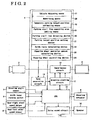
- Fig2 illustrates a block diagram indicating the parlcing assist ECU 4.
- the parking assist ECU 4 mainly includes a CPU 11 for controlling the parking ECU 4, a graphics plotting circuit 12 for plotting a graphic image on the display 3, a superimpose circuit 13 for superimposing graphics signals on a rear image captured by the rear camera 2, a sync separation circuit 14 for selecting synchronized signals from the camera image and providing it to the graphics plotting circuit 12 and a voice sound circuit 15 for outputting audible guide tone through a speaker 16 of the vehicle 1.
- the parking assist ECU 4 includes a vehicle detecting device ( serving as a vehicle detecting means) 17, a memory (serving as a memorizing means)28, a temporary parking target position estimating device ( serving as a temporary packing target position estimating means)18, a parking stall line searching area setting device ( serving as a parking stall line searching area setting means )19, a parking stall line detecting device 20, a parking target position setting device 21, a guide route calculating device(serving as a guide route calculating means )22, a steering wheel operation amount calculating device ( serving as a steering wheel operation amount calculating means)23, and a steering wheel controlling device (serving as a steering wheel controlling means) 24.
- a vehicle detecting device serving as a vehicle detecting means 17
- a memory serving as a memorizing means
- a temporary parking target position estimating device serving as a temporary packing target position estimating means
- a parking stall line searching area setting device serving as a parking stall line searching area setting means )19
- the vehicle detecting device 17 detects a vehicle, which is moving, and the memory 28 memorizes a vehicle moving trajectory detected by the vehicle detecting device 17.
- the vehicle moving trajectory includes the steering angle of the vehicle 1 and he wheel speed of the vehicle 1.
- the memory 28 always stores data of the latest trajectory (e.g., trajectory within seven meters), and once the memory reaches full capacity, old data will be deleted in order to make the space for latest data. Thus, latest data can be sequentially memorized.
- the temporary parking target position estimating device 18 assumes a temporary parking target position k on the basis of a variation of the vehicle moving trajectory.
- the parking stall line searching area setting device 19 sets a parking stall line searching area S, which is used for searching a parking stall line T, on the basis of the temporary parking target position k.
- the parking stall line detecting device 20 detects the parking stall line T within a parking stall line searching area S.
- the parking target position setting device 21 set a parking target position K on the basis of the detected parking stall line T.
- the guide route calculating device 22 calculates a guide route, which is used for guiding the vehicle to the parking target position K.
- the steering wheel operation amount calculating device 23 calculates a steering wheel operation amount of the vehicle 1 on the basis of the guide route.
- the steering wheel controlling device 24 automatically controls the operation of the steering wheel of the vehicle 1 on the basis of the steering wheel operation amount.
- the steering angle sensor 5, the shift lever reverse switch 6, the rear-right wheel speed sensor 7, the rear-left wheel speed sensor 8 and the like are connected to the CPU 11, and each of them outputs detecting signals. Further, the steering actuator 9 is connected to the CPU 11 in order to adjust a force, which is used for rotating the steering, on the basis of control signals, which are outputted by the steering wheel controlling device 24. Thus, the steering wheel can be automatically operated.
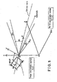
- Fig.3 illustrates a diagram indicating a coordinate conversion by means of the parking assist ECU 4.
- a projection transformation for displaying the parking target position setting a world coordinate system, which is predetermined to a vehicle before starting the guide operation, to X-Y-Z, and setting an image coordinate system of the rear camera 2 to x-y, a plot point A (Xi, Yi, Zi) on the world coordinate is transformed into a point a ( xi, yi ) of the image coordinate on the basis of following Formula 1 and Formula 2.
- a P [ A 1 ]
- P C [ R / T ]
- P indicates a projection transformation matrix of 3 x4
- C indicates a inner parameter of the camera
- R indicates a rotational movement
- T indicates a parallel movement.
- Fig.4 illustrates a diagram indicating a method for detecting a moving distance of the vehicle 1 by the parking assist ECU 4.
- the moving distance of the vehicle 1 can be calculated by the following Formulas 3, 4 and 5.
- the “ds” indicates a minor moving distance and calculated on the basis of the rotation amount of the wheel that is detected by the vehicle wheel speed sensors 7 and 8 provided at the rear right and left wheels.
- the “R” indicates a turning radius of the vehicle 1 and calculated on the basis of a value detected by the steering angle sensor 5.
- the “ ⁇ ” indicates an accumulated moving distance from a position where the parking operation is started.
- Fig.5 illustrates a flow chart indicating a process of the packing assist ECU 4.
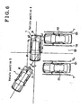
- Figs.6 through 11 are explanation drawings that indicate the vehicle 1, which is backed-in so as to be parallel.
- the parking assist ECU 4 starts a program illustrates in the flowchart in Fig.5.
- a driver of the vehicle 1 when the driver intends to park the vehicle 1 into a parking stall G2, which is not occupied and provided so as to be parallel to parking stalls G1 and G3, which are occupied with another vehicles, a driver of the vehicle 1 usually temporally stops the vehicle 1 at a posffion where the driver can carefully observe the parking stall G2 in a manner where a drivers seat is positioned on a central line of the parking stall G2.
- a step 1 (herein below referred to as S1) in Fig.5, considering that the temporary stop of the vehicle 1 at a vehicle position A as a trigger, the parking assist ECU 4 starts calculating a vehicle moving amount dX, dZ form the vehicle position A and ⁇ relative to the vehicle position A.
- dX and dZ are calculated on a basis of a central point M of the rear wheel shaft.
- Ix1 shown in Fig.7 is calculated as a distance from the central point M to the drivers seat, and Iz1is calculated as a distance from the central point M to a point, which is distanced from the central point M at the distance of dZ in the opposite direction thereof relative to the axis Z.
- the driver moves and turns the vehicle 1 rightward from the vehicle position A to a vehicle position B in order to back-in the vehicle 1 into the parking stall G2, which is located, at this moment, at left hand of the vehicle.
- the parking assist ECU 4 detect “on” or “off” of the shift lever reverse switch 6 in order to determine whether or not the shift is positioned to the reverse mode.
- the parking assist ECU 4 becomes a stand-by mode.
- the parking assist ECU 4 goes to S3 and executes a calculation in order to assume the parking target position.
- a right-left direction of the vehicle 1 as an X axis, and a front-rear direction of the vehicle 1 as Z axis on the basis of values of dX, dZ, Ix1, Iz1 and Iz2, which are indicated in Fig.7, a relative position of the temporary parking target position k relative to an assumed direction Lc of the parking stall G2 in X-Z coordinate system at the vehicle position B is calculated.
- the parking assist ECU 4 reads the vehicle moving trajectory of steering angle and the vehicle wheel speed from the memory 28 and calculates deflection angle ⁇ of the vehicle 1 per unit time. Then, the parking assist ECU 4 determines whether or not the vehicle 1 moves forward from the deflection angle ⁇ and the vehicle 1 turns with describing an arc. Generally, when the vehicle 1 is backed into the parking stall, which is positioned on the left hand, the driver of the vehicle 1 moves the vehicle 1 forward passing in front of the parking stalls G and turns the vehicle 1 in a right direction.
- the driver of the vehicle moves the vehicle forward assign through the parking stalls G and turns the vehicle 1 in a left direction.
- it can be predicted from the turning direction whether the vehicle 1 will be parked into the parking stall G on the left hand or the parking stall F on the right hand.
- it is predicted that the vehicle 1 will be parked into the parking stall G2.
- the vehicle 1 When the vehicle 1 is parked into the parking stall G2 located on the left band, the driver moves the vehicle 1 backward from the vehicle position B, turns the steering wheel in a left direction, then moves the vehicle 1 straight-backward, as a result, the vehicle 1 can be parked into a parking stall G, which is located so as to be orthogonal relative to the Z axis of the vehicle position A.
- the assumed direction Lc of the parking stall G is calculated as a straight line having a phase difference at a certain angle, which is calculated by adding an angle of 90 degrees to the deflection angle ⁇ toward the parking stall G side relative to an optical axis of the vehicle position B.
- the temporary parking target position k is calculated as a position relative to the vehicle position B in the X-Y coordinate series.
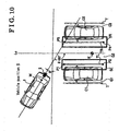
- a right packing stall line TR and a left parking stall line TL which are used for compartmentalizing the parking stall G, are approximately predetermined of their leugths, widths, distances therebetween.
- a position of the right parking stall line TR and a position of the left parking stall line TL are predicted, and further, a parking stall line searching area S, which is used for searching the right and left parking stall lines TL and TR are set.
- a left parking stall line searching area SL which are used for searching the left parking stall line TL
- a right parking stall line searching area SR which are used for searching the right parking stall line TR
- the left parking stall line searching area SL and the right parking stall line searching area SR are set so as to be wider than the size of the parking stall line T and so as not to include three parking stall lines T or more.
- the right parking stall line TR can be included in the right parking stall searching area SR, and the left parking stall line TL can be included in the left parking stall searching area SL, at the same time, it can be prevented that plural parking stalls G are detected within the single parking stall line searching area R, as a result, chances that the parking stall line T is not detected or incorrectly detected can be reduced.
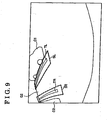
- Fig.9 illustrates an image showing the right parking stall line searching area SR and the left parking stall line searching area SL, which are superposed on the rear image captured by the rear camera 2.
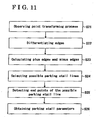
- Fig.11 illustrates a flow chart indicating a method for detecting the parking stall line of the parking stall.
- an observing point transforming process is executed. Specifically, the image captured by the rear camera 2 is transformed from the world coordinate into the image coordinate.
- the right and left parking stall line searching areas SR and SL are scanned with a spatial filter of 3x3 pixel in order to obtain intensities thereof, and such intensities are differentiated for each area corresponding to the spatial filter in order to obtain intensity differences.
- the process proceeds to S23, and each of the intensity differences is compared to a plus threshold and a minus threshold, and if the intensity difference is greater than the plus threshold, a plus edge is set, and if the intensity difference is lower than the minus threshold, a minus edge is set. Then, the process proceeds to S24, and combinations of the plus edges and the minus edges and an alignment of the plus edges and an alignment of the minus edges are calculated. For example it is determined whether or not a series of the plus edges and the series of the minus edges are parallel and distanced each other at a predetermined length, which corresponds to a width of the parking stall line.
- a pair of a plus edge line and a minus edge line are detected, and thus, a possible parking stall line can be selected from the image.
- the process proceeds to S25, and end points of each of the plus edge line and a minus edge line, which are selected as the possible parking stall line, are searched.
- the right and left parking stall lines TL and TR and end points P1, P2, P3. and P4 shown in Fig.10 are obtained as parking stall parameters in S25 and S26.
- the temporary parking target position k is set to be the parking target position K.
- a parking target frame W is calculated so as to be positioned to the central point M of the vehicle 1.
- the calculated parking target frame W is superposed on the image captured by the rear camera 2 and displayed on the display 3.
- This parking target frame W is considered as an initial position thereof.
- a position adjusting switch 25 is also displayed on the display 3 together with the captured rear image and the parking target frame W.
- the driver can adjust the position of the parking target frame W within the parking stall G2 in S6. Specifically, the driver can move the parking target frame W in a vertical direction of the display 3 by pressing an upper direction arrow Y1 or a lower direction arrow Y2, which are appears on the display 3, and the driver can move the parking target frame W in a horizontal direction of the display 3 by pressing a left direction arrow Y3 and a right direction arrow Y4, which also appear on the display 3.
- the driver can rotate the parking target frame W in a clockwise direction of an anticlockwise direction by pressing a rotational arrow Y5 and a rotational arrow Y6.
- a position of the parking target position K can also be adjusted automatically.
- the parking assist operation can be stopped.
- a guide route which is used for guiding the vehicle 1 from the vehicle position B to the parking target position K, is calculated.
- the process proceeds to S8, and it is determined whether or not the driver adjusts the position of the parking target position K depending on whether or not the position adjusting switch 25 has been operated.
- the process goes-back to S7 and the guide-route, which is used for guiding the vehicle 1 from the vehicle position B to an adjusted parking target position K', is calculated.
- the driver turns on the confirmation switch 27 in order to determine that the parking target position K is confirmed If the confirmation switch 27 has not been turned on (S9:NO), the process goes back to S8 and standby until the parking target position K is adjusted. Then, when it is detected that the confirmation switch 27 is turned on ( S9:YES ), the process proceeds to S10, and an announcement such as "parking assist operation now starts” is output from the speaker 16 in order to notify the driver of starting the operation.
- the parking assist ECU 4 inputs a speed signal, which is detected and output by the rear-right wheel speed sensor 7 and the rear-left wheel speed sensor 8, input a steering angle signal detected and output by the steering angle sensor 5 in order to calculate the moving amount of the vehicle 1, and then a position of the vehicle 1 relative to the guide route is detected.
- a target steering angle relative to the guide route is calculated, and in S 13, the steering actuator 9 is controlled on the basis of the target steering angle. In this configuration, the steering wheel of the vehicle 1 is automatically rotated, and, when the driver stomps on the accelerator, the vehicle 1 starts moving in a rear direction toward the parking target position K.
- S 14 it is determined whether or not the vehicle reaches the parking target position K. If it is determined that the vehicle 1 does not reach the parking target position K (S14:NO), the process goes back to S11 and continues to control the steering wheel. On the other hand, if it is determined that the vehicle 1 reaches the parking target position K ( S14:YES ), it is determined that the parking operation is finished, and then the parking assist operation is finished.
- the movement of the vehicle can be detected by the vehicle detecting device 17, the steering angle and the vehicle wheel speed are memorized in the memory 28 as the vehicle moving trajectory. Further, the temporary parking target position estimating device 18 reads the vehicle moving trajectory from the memory 28 and obtains information about how the vehicle has moved, in order to assume the temporary parking target position k. Because the moving locus of the vehicle 1 may differ depending on driving characteristics of the driver or a situation of the parking, the temporary parking target position k may not be included in the parking stall G2.
- the parking assist ECU 4 of this embodiment sets the parking target position K as follows.
- the parking stall line searching area setting device 19 sets the parking stall line searching area S within which the parking stall line T will be searched on the basis of the temporary parking target position k. After the image captured by the rear camera 2 is inputted into the parking assist ECU 4, the parking stall line T is detected within the parking stall line searching area S I the image.
- the parking stall line T is detected only from the parking stall line searching area S, disturbances (such as differences of levels of brightness, shadow of other vehicles C1 and C2, dirt on the load surface and the like), which occurs outside the parking stall line searching area S, can be eliminated, as a result, an accuracy on detecting the parking stall line T can be enhanced, and the number, of the calculations for detecting the parking stall line T can be reduced.
- the parking stall line T can be determined by correcting the temporary parking target position k on the basis of the parking stall line T.
- the parking target position K can be determined with high accuracy, as a result chances that the driver resets the parking target position K by means of the position adjusting switch 25 can be reduced.
- the parking stall line T can be detected from the parking stall line searching area S, comparing to a case when the parking stall line T is detected from an entire image, a time for detecting the parking stall line T can be shortened, as a result, a time for setting the parking target position K can also be shortened.
- the parking target position K can be set with high accuracy and high speed, as a result, hassles for the user when the parking target position K is set can be reduced.
- the temporary parking target position estimating device 19 calculates a first point, at which the vehicle 1 temporally stops, a deflection angle ⁇ at which the vehicle 1 rotates from the first position, and a moving distance of the vehicle 1 from the first position to a second position, at which the vehicle 1 turns at the predetermined deflection angle ⁇ , on the basis of the vehicle moving trajectory.
- the temporary parking target position k is assumed.
- the shift lever reverse switch 6 when the driver positions the shift lever to the reversed mode, the shift lever reverse switch 6 is turned on. Once the shift lever reverse switch 6 is turned on, the parking assist instruction is inputted into the temporary parking target position estimating device 19, and the temporary parking target position k is assumed by the temporary parking target position estimating device 19. On the basis of the assumed temporary parking target position k, in order to assist a parking operation of the vehicle 1, the parking stall line T is detected; and the parking target position is set.
- the temporary parking target position k is assumed when the shift lever reverse switch 6 is turned on, in other words, the tumed-on operation of the shift lever reverse switch 6 is considered as a trigger; chances that the temporary parking target position k is assumed when, for example, the driver doesn't need the parking assist operation, can be reduced, as a result, needless calculations can be reduced.
- the left packing stall line searching area SL and the right parking stall line searching area SR are set separately, and each of the left parking stall line searching area SL and the right parking stall line searching area SR is scanned in order to detect the left parking stall line TL and the right parking stall line TR.
- elements such as intensity differences, which occur within an area defined between the right parking stall line TR and the left parking stall line TL, can be eliminate, as a result, an accuracy on detecting the right parking stall line TR and the left parking stall line TL can be enhanced.
- the number of the calculations can be reduced; as a result, calculation costs can also be reduced.
- the steering wheel operation amount calculating device 23 calculates the steering wheel operation amount for the vehicle 1 on the basis of the guide route. Then, the steering wheel controlling device 24 automatically controls the steering wheel of the vehicle 1 on the basis of the steering wheel operation amount in order to park the vehicle 1 into the parking stall G2. In this configuration, even a driver who is not good at parking can park the vehicle 1 into the parking stall G2 without any trouble.
- the present invention is not limited to the above embodiment, and can be altered as following examples or applied to many cases.
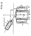
- the right parking stall line searching area SR and the left parking stall line searching area SL are set separately, however, only one parking stall line searching area S, which includes both the right parking stall line searching area SR and the left parking stall line searching area SL, may be set as shown in Fig.l3.
- the parking stall line searching area S may be set so as to be larger than the parking stall G2 in order to detect each of the right parking stall lines TR and the left parking stall lines TL with high accuracy.
- the parking stall line searching area may be set so as to be larger than the parking stall G2 in order to detect each of the right parking stall lines TR and the left parking stall lines TL with high accuracy.
- a dispersion within the entire the parking stall line searching area S can be averaged in order to enhance the level of the accuracy of detecting the right parking stall line TR and the left parking stall line TL.
- a parking stall GX into which the driver intends to park the vehicle 1, can be assumed on the basis of the temporally stop position, the deflection angle and the moving distance, and then the temporary parking target position k is assumed. Then the parking stall line searching area S can be set, and finally the parking target position K can be set with high accuracy.
- the shift lever reverse switch 6 is housed in the shift lever and automatically turned on and off when the shift lever is positioned to the reversed mode, however, this parking assist instruction switch can be provided, for example, at the center console, and can be turned on and off manually by the driver.
- the temporary parking target position k is assumed on the basis of the temporally stop position, the deflection angle and the moving distance, however, the temporary parking target position k may be assumed on the basis of, for example only the deflection angle. In this configuration, the calculation costs can be reduced.
- a parking assist device (4) detecting a parking stall line from an image captured by a capturing portion (2); setting a parking target position (K) on the basis of the parking stall line; and assisting the vehicle to travel to the parking target position, characterized in that the parking assist device includes a vehicle detecting portion (17) for detecting a movement of the vehicle, a memorizing portion (28) for memorizing the movement detected by the vehicle detecting portion, as a vehicle moving trajectory, a temporary parking target position estimating portion (18) for assuming a temporary parking target position (k) on the basis of variations of the vehicle moving trajectory memorized by the memorizing portion; and a parking stall line searching area setting portion (19) for setting a parking stall line searching area (SR) (SL), within which a parking stall line (TR) (TL) is searched on the basis of the temporary paiking target position.
- SR parking stall line searching area
- TR parking stall line
Applications Claiming Priority (1)
| Application Number | Priority Date | Filing Date | Title |
|---|---|---|---|
| JP2004369136A JP4604703B2 (ja) | 2004-12-21 | 2004-12-21 | 駐車補助装置 |
Publications (3)
| Publication Number | Publication Date |
|---|---|
| EP1674376A2 true EP1674376A2 (de) | 2006-06-28 |
| EP1674376A3 EP1674376A3 (de) | 2006-11-22 |
| EP1674376B1 EP1674376B1 (de) | 2008-12-03 |
Family
ID=36084199
Family Applications (1)
| Application Number | Title | Priority Date | Filing Date |
|---|---|---|---|
| EP05027518A Expired - Fee Related EP1674376B1 (de) | 2004-12-21 | 2005-12-15 | Parkhilfseinrichtung |
Country Status (5)
| Country | Link |
|---|---|
| US (2) | US7706944B2 (de) |
| EP (1) | EP1674376B1 (de) |
| JP (1) | JP4604703B2 (de) |
| CN (1) | CN1793785B (de) |
| DE (1) | DE602005011390D1 (de) |
Cited By (5)
| Publication number | Priority date | Publication date | Assignee | Title |
|---|---|---|---|---|
| EP2145799A1 (de) * | 2007-05-16 | 2010-01-20 | Aisin Seiki Kabushiki Kaisha | Parkhilfesystem |
| EP2228276A3 (de) * | 2009-03-11 | 2011-06-29 | Aisin Seiki Kabushiki Kaisha | Einparkunterstützungsvorrichtung |
| EP2776295A1 (de) * | 2011-11-08 | 2014-09-17 | LG Innotek Co., Ltd. | Parkhilfesystem |
| EP2981073A4 (de) * | 2013-03-29 | 2016-03-23 | Panasonic Ip Man Co Ltd | Parkhilfevorrichtung und parkhilfeverfahren |
| EP3300992A1 (de) * | 2016-09-28 | 2018-04-04 | Dura Operating, LLC | System und verfahren zum autonomen quereinparken eines fahrzeugs |
Families Citing this family (98)
| Publication number | Priority date | Publication date | Assignee | Title |
|---|---|---|---|---|
| DE102004027640A1 (de) * | 2004-06-05 | 2006-06-08 | Robert Bosch Gmbh | Verfahren und Vorrichtung zum unterstützten Einparken eines Kraftfahrzeuges |
| KR101320223B1 (ko) * | 2005-12-23 | 2013-10-21 | 콘티넨탈 테베스 아게 운트 코. 오하게 | 자동차를 주차하거나 운전할 때 운전자를 돕기 위한 방법및 시스템 |
| JP2007176244A (ja) * | 2005-12-27 | 2007-07-12 | Aisin Seiki Co Ltd | 駐車支援装置 |
| DE102006007343A1 (de) * | 2006-02-17 | 2007-08-30 | Robert Bosch Gmbh | Bilderfassungseinrichtung für ein Fahrerassistenzsystem |
| WO2007105518A1 (ja) * | 2006-03-14 | 2007-09-20 | Pioneer Corporation | 位置登録装置、経路探索装置、位置登録方法、位置登録プログラムおよび記録媒体 |
| JP4769625B2 (ja) * | 2006-04-25 | 2011-09-07 | トヨタ自動車株式会社 | 駐車支援装置及び駐車支援方法 |
| JP4432929B2 (ja) * | 2006-04-25 | 2010-03-17 | トヨタ自動車株式会社 | 駐車支援装置及び駐車支援方法 |
| JP4863791B2 (ja) * | 2006-07-05 | 2012-01-25 | アルパイン株式会社 | 車両周辺画像生成装置および画像切替方法 |
| JP2008143430A (ja) * | 2006-12-12 | 2008-06-26 | Toyota Motor Corp | 駐車支援装置 |
| JP4386083B2 (ja) | 2007-02-27 | 2009-12-16 | トヨタ自動車株式会社 | 駐車支援装置 |
| GB2447672B (en) | 2007-03-21 | 2011-12-14 | Ford Global Tech Llc | Vehicle manoeuvring aids |
| JP5105149B2 (ja) * | 2007-04-18 | 2012-12-19 | アイシン精機株式会社 | 駐車支援装置 |
| JP4863922B2 (ja) * | 2007-04-18 | 2012-01-25 | 三洋電機株式会社 | 運転支援システム並びに車両 |
| JP4872791B2 (ja) * | 2007-05-11 | 2012-02-08 | トヨタ自動車株式会社 | 駐車支援装置 |
| JP5003946B2 (ja) * | 2007-05-30 | 2012-08-22 | アイシン精機株式会社 | 駐車支援装置 |
| JPWO2009016925A1 (ja) * | 2007-07-31 | 2010-10-14 | 株式会社豊田自動織機 | 駐車支援装置、駐車支援装置の車両側装置、駐車支援方法及び駐車支援プログラム |
| US8319663B2 (en) * | 2007-11-08 | 2012-11-27 | Bosch Corporation | Parking assist system |
| KR101221732B1 (ko) * | 2007-12-21 | 2013-01-11 | 주식회사 만도 | 노면의 상태에 따라 주차 보조 기능을 비활성화 상태로전환하는 방법 및 장치 |
| DE102008003662A1 (de) * | 2008-01-09 | 2009-07-16 | Robert Bosch Gmbh | Verfahren und Vorrichtung zum Anzeigen der Umgebung eines Fahrzeugs |
| DE102008004632A1 (de) * | 2008-01-16 | 2009-07-23 | Robert Bosch Gmbh | Vorrichtung und Verfahren zur Vermessung einer Parklücke |
| DE102008027779A1 (de) * | 2008-06-11 | 2009-12-17 | Valeo Schalter Und Sensoren Gmbh | Verfahren zur Unterstützung eines Fahrers eines Fahrzeugs beim Einparken in eine Parklücke |
| US8705792B2 (en) * | 2008-08-06 | 2014-04-22 | Toyota Motor Engineering & Manufacturing North America, Inc. | Object tracking using linear features |
| CN101727756B (zh) * | 2008-10-16 | 2012-07-25 | 财团法人工业技术研究院 | 交通工具移动图像辅助导引方法与系统 |
| JP5316805B2 (ja) * | 2009-03-16 | 2013-10-16 | 株式会社リコー | 車載カメラ装置の画像調整装置及び車載カメラ装置 |
| TW201100279A (en) * | 2009-06-23 | 2011-01-01 | Automotive Res & Testing Ct | Composite-image-type parking auxiliary system |
| CN102085864B (zh) * | 2009-12-04 | 2013-07-24 | 财团法人工业技术研究院 | 控制车辆停车的方法与控制车辆停车系统 |
| DE102009060169A1 (de) * | 2009-12-23 | 2011-06-30 | Volkswagen AG, 38440 | Automatisches Vorwärtseinparken in Kopfparklücken |
| GB2464413B (en) * | 2010-01-05 | 2014-07-02 | Protean Electric Ltd | Control Device for a Vehicle |
| DE102010011496A1 (de) * | 2010-03-16 | 2011-09-22 | GM Global Technology Operations LLC , (n. d. Ges. d. Staates Delaware) | Verfahren zur selektiven Anzeige von Informationen eines Kamerasystems in einer Anzeigevorrichtung eines Fahrzeugs und Fahrzeug mit einem Kamerasystem |
| DE102010020204A1 (de) * | 2010-05-12 | 2011-11-17 | Volkswagen Ag | Verfahren zum Einparken eines Fahrzeugs sowie entsprechendes Einparkassistenzsystem und Fahrzeug |
| MY164070A (en) * | 2010-06-11 | 2017-11-15 | Nissan Motor | Parking assist apparatus and method |
| JP5472026B2 (ja) * | 2010-06-29 | 2014-04-16 | トヨタ自動車株式会社 | 駐車支援装置 |
| US8665116B2 (en) * | 2010-07-18 | 2014-03-04 | Ford Global Technologies | Parking assist overlay with variable brightness intensity |
| CN102372000B (zh) * | 2010-08-23 | 2014-02-05 | 北京经纬恒润科技有限公司 | 获取泊车位参数的装置和系统 |
| CN102371949A (zh) * | 2010-08-25 | 2012-03-14 | 富泰华工业(深圳)有限公司 | 倒车系统及倒车方法 |
| JP5212748B2 (ja) | 2010-09-29 | 2013-06-19 | アイシン精機株式会社 | 駐車支援装置 |
| US9723274B2 (en) | 2011-04-19 | 2017-08-01 | Ford Global Technologies, Llc | System and method for adjusting an image capture setting |
| US9937953B2 (en) | 2011-04-19 | 2018-04-10 | Ford Global Technologies, Llc | Trailer backup offset determination |
| US9926008B2 (en) | 2011-04-19 | 2018-03-27 | Ford Global Technologies, Llc | Trailer backup assist system with waypoint selection |
| US9783230B2 (en) | 2011-04-19 | 2017-10-10 | Ford Global Technologies, Llc | Trailer backup assist system with off-shoot correction |
| US9708000B2 (en) | 2011-04-19 | 2017-07-18 | Ford Global Technologies, Llc | Trajectory planner for a trailer backup assist system |
| US20150197281A1 (en) * | 2011-04-19 | 2015-07-16 | Ford Global Technologies, Llc | Trailer backup assist system with lane marker detection |
| US9854209B2 (en) | 2011-04-19 | 2017-12-26 | Ford Global Technologies, Llc | Display system utilizing vehicle and trailer dynamics |
| US9969428B2 (en) * | 2011-04-19 | 2018-05-15 | Ford Global Technologies, Llc | Trailer backup assist system with waypoint selection |
| US8799201B2 (en) | 2011-07-25 | 2014-08-05 | Toyota Motor Engineering & Manufacturing North America, Inc. | Method and system for tracking objects |
| JP5682788B2 (ja) * | 2011-09-27 | 2015-03-11 | アイシン精機株式会社 | 車両周辺監視装置 |
| DE102011086281A1 (de) * | 2011-11-14 | 2013-05-16 | Robert Bosch Gmbh | Verfahren und Vorrichtung zum Bestimmen einer Ausparkstrategie |
| CN102616184A (zh) * | 2012-04-18 | 2012-08-01 | 北京兴科迪科技有限公司 | 交通工具倒车影像系统及装有该系统的车辆交通工具 |
| KR101316465B1 (ko) * | 2012-06-29 | 2013-10-08 | 현대자동차주식회사 | 충돌 방지 시스템 및 방법 |
| US20140055615A1 (en) * | 2012-08-27 | 2014-02-27 | Stephen Chen | Parking assistant device |
| JP5849942B2 (ja) * | 2012-12-25 | 2016-02-03 | 株式会社日本自動車部品総合研究所 | 車載画像処理装置 |
| JP6094266B2 (ja) * | 2013-02-28 | 2017-03-15 | アイシン精機株式会社 | 駐車支援装置、駐車支援方法およびプログラム |
| KR101449295B1 (ko) | 2013-06-04 | 2014-10-13 | 현대자동차주식회사 | 주차구획 추적 장치 및 방법 |
| US9323993B2 (en) | 2013-09-05 | 2016-04-26 | Xerox Corporation | On-street parking management methods and systems for identifying a vehicle via a camera and mobile communications devices |
| KR101511992B1 (ko) * | 2013-09-06 | 2015-04-14 | 현대모비스(주) | 조향 휠 제어 방법 및 이를 위한 위한 시스템 |
| US9333908B2 (en) | 2013-11-06 | 2016-05-10 | Frazier Cunningham, III | Parking signaling system |
| US11241970B2 (en) | 2013-11-14 | 2022-02-08 | Momentum Dynamics Corporation | Method and apparatus for the alignment of vehicles prior to wireless charging |
| US10814729B2 (en) * | 2013-11-14 | 2020-10-27 | Momentum Dynamics Corporation | Method and apparatus for the alignment of a vehicle and charging coil prior to wireless charging |
| DE102014202324A1 (de) * | 2014-02-10 | 2015-08-13 | Conti Temic Microelectronic Gmbh | Verfahren und Vorrichtung zum sicheren Parken eines Fahrzeugs |
| JP6100222B2 (ja) * | 2014-09-12 | 2017-03-22 | アイシン精機株式会社 | 駐車支援装置 |
| KR101583998B1 (ko) * | 2014-10-17 | 2016-01-19 | 현대자동차주식회사 | 주차지원장치 및 방법 |
| JP6227514B2 (ja) * | 2014-10-27 | 2017-11-08 | アイシン精機株式会社 | 駐車支援装置 |
| JP6500435B2 (ja) * | 2014-12-26 | 2019-04-17 | アイシン精機株式会社 | 駐車支援装置 |
| US10286950B2 (en) | 2015-02-10 | 2019-05-14 | Ford Global Technologies, Llc | Speed optimized trajectory control for motor vehicles |
| US9751558B2 (en) | 2015-03-25 | 2017-09-05 | Ford Global Technologies, Llc | Handwheel obstruction detection and inertia compensation |
| US9623859B2 (en) | 2015-04-03 | 2017-04-18 | Ford Global Technologies, Llc | Trailer curvature control and mode management with powertrain and brake support |
| US9840240B2 (en) | 2015-04-09 | 2017-12-12 | Ford Global Technologies, Llc | Trailer backup aid speed limiting via braking |
| KR101647996B1 (ko) * | 2015-05-29 | 2016-08-23 | 주식회사 케이에스에스이미지넥스트 | 차량의 자동 주차 방법 및 시스템 |
| US9896126B2 (en) | 2015-07-08 | 2018-02-20 | Ford Global Technologies, Llc | Jackknife detection for vehicle reversing a trailer |
| KR102327345B1 (ko) * | 2015-07-14 | 2021-11-17 | 주식회사 만도모빌리티솔루션즈 | 주차제어시스템 및 그 제어방법 |
| CN105118054B (zh) * | 2015-08-03 | 2018-09-14 | 长安大学 | 一种基于ccd单目测距的驾驶考试系统 |
| US9679485B2 (en) * | 2015-09-11 | 2017-06-13 | International Business Machines Corporation | Determining a parking position based on visual and non-visual factors |
| US9981656B2 (en) | 2015-10-13 | 2018-05-29 | Ford Global Technologies, Llc | Vehicle parking assist system |
| US9981662B2 (en) | 2015-10-15 | 2018-05-29 | Ford Global Technologies, Llc | Speed limiting comfort enhancement |
| US9836060B2 (en) | 2015-10-28 | 2017-12-05 | Ford Global Technologies, Llc | Trailer backup assist system with target management |
| US10328933B2 (en) | 2015-10-29 | 2019-06-25 | Ford Global Technologies, Llc | Cognitive reverse speed limiting |
| CN107031523A (zh) * | 2015-11-30 | 2017-08-11 | 法乐第未来公司 | 利用已知目标进行基于摄像头的车辆位置确定 |
| US9895945B2 (en) | 2015-12-08 | 2018-02-20 | Ford Global Technologies, Llc | Trailer backup assist system with hitch assist |
| CN105774815A (zh) * | 2016-03-07 | 2016-07-20 | 江苏大学 | 一种高适应性人机交互型智能泊车方法 |
| WO2017159510A1 (ja) * | 2016-03-18 | 2017-09-21 | 京セラ株式会社 | 駐車支援装置、車載カメラ、車両および駐車支援方法 |
| WO2018005819A1 (en) * | 2016-07-01 | 2018-01-04 | nuTonomy Inc. | Affecting functions of a vehicle based on function-related information about its environment |
| JP6305484B2 (ja) * | 2016-09-12 | 2018-04-04 | 本田技研工業株式会社 | 車両制御装置 |
| US9829883B1 (en) | 2016-10-17 | 2017-11-28 | Ford Global Technologies, Llc | Trailer backup assist system having remote control and user sight management |
| US10773721B2 (en) | 2016-10-21 | 2020-09-15 | Ford Global Technologies, Llc | Control method using trailer yaw rate measurements for trailer backup assist |
| KR102340356B1 (ko) * | 2017-04-25 | 2021-12-16 | 주식회사 만도모빌리티솔루션즈 | 자동주차제어장치 및 자동주차제어방법 |
| JP2018184149A (ja) * | 2017-04-27 | 2018-11-22 | アイシン精機株式会社 | 駐車支援装置 |
| JP6785960B2 (ja) * | 2017-06-07 | 2020-11-18 | 三菱電機株式会社 | 空きスペース通知装置、空きスペース通知システム及び空きスペース通知方法 |
| US10604184B2 (en) | 2017-08-31 | 2020-03-31 | Ford Global Technologies, Llc | Adaptive steering control for robustness to errors in estimated or user-supplied trailer parameters |
| US10710585B2 (en) | 2017-09-01 | 2020-07-14 | Ford Global Technologies, Llc | Trailer backup assist system with predictive hitch angle functionality |
| CN107745710B (zh) * | 2017-09-12 | 2019-08-02 | 南京航空航天大学 | 一种基于机器视觉与机器学习的自动泊车方法及系统 |
| US10730553B2 (en) | 2017-09-27 | 2020-08-04 | Ford Global Technologies, Llc | Adaptive steering control for robustness to errors in estimated or user-supplied trailer parameters |
| US10583779B2 (en) | 2017-10-02 | 2020-03-10 | Magna Electronics Inc. | Parking assist system using backup camera |
| US10821972B2 (en) * | 2018-09-13 | 2020-11-03 | Ford Global Technologies, Llc | Vehicle remote parking assist systems and methods |
| US10814912B2 (en) | 2018-11-28 | 2020-10-27 | Ford Global Technologies, Llc | Trailer backup assist system having advanced user mode with selectable hitch angle limits |
| JP7203587B2 (ja) * | 2018-12-14 | 2023-01-13 | 株式会社デンソーテン | 画像処理装置および画像処理方法 |
| CN112622761B (zh) * | 2019-09-24 | 2022-07-29 | 博泰车联网科技(上海)股份有限公司 | 一种倒车显示方法、装置及计算机存储介质 |
| US11721113B2 (en) | 2020-10-09 | 2023-08-08 | Magna Electronics Inc. | Vehicular driving assist system with lane detection using rear camera |
| DE102021127748A1 (de) | 2021-10-26 | 2023-04-27 | Valeo Schalter Und Sensoren Gmbh | Verfahren, computerprogrammprodukt, parkassistenzsystem und fahrzeug |
Citations (8)
| Publication number | Priority date | Publication date | Assignee | Title |
|---|---|---|---|---|
| DE2901504B1 (de) * | 1979-01-16 | 1980-06-26 | Richard Dipl-Ing Haemmerle | Verfahren und Vorrichtung zum Einparken von Kraftfahrzeugen |
| DE10041381A1 (de) * | 1999-08-26 | 2001-04-05 | Honda Motor Co Ltd | Automatisches Fahrzeug-Lenksystem |
| US20020041239A1 (en) * | 2000-07-27 | 2002-04-11 | Yasuo Shimizu | Parking aid system |
| EP1249379A2 (de) * | 2001-04-09 | 2002-10-16 | DaimlerChrysler AG | Verfahren und Vorrichtung zum Verbringen eines Kraftfahrzeuges in eine Zielposition |
| EP1270367A2 (de) * | 2001-06-29 | 2003-01-02 | Kabushiki Kaisha Toyota Jidoshokki | Parkhilfe |
| JP2003205807A (ja) * | 2002-01-10 | 2003-07-22 | Toyota Motor Corp | 駐車支援装置 |
| EP1469422A1 (de) * | 2003-04-14 | 2004-10-20 | Kabushiki Kaisha Toyota Jidoshokki | Einparkhilfe |
| EP1468893A2 (de) * | 2003-04-11 | 2004-10-20 | Toyota Jidosha Kabushiki Kaisha | Verfahren und Vorrichtung zur Unterstützung beim Einparken |
Family Cites Families (33)
| Publication number | Priority date | Publication date | Assignee | Title |
|---|---|---|---|---|
| JPS59201082A (ja) | 1983-04-30 | 1984-11-14 | 日産自動車株式会社 | 駐車アシスト装置 |
| US4931930A (en) * | 1988-04-19 | 1990-06-05 | Industrial Technology Research Institute | Automatic parking device for automobile |
| JPH06111198A (ja) | 1992-09-29 | 1994-04-22 | Toyota Motor Corp | 駐車空間検出装置 |
| US5402475A (en) * | 1993-03-31 | 1995-03-28 | Schlumberger Technologies, Inc. | Monitoring and control of parking management system by remote |
| US5504314A (en) * | 1993-06-29 | 1996-04-02 | Farmont; Johann | Monitoring and/or directing system for parking areas |
| US5384524A (en) * | 1993-09-02 | 1995-01-24 | Cirrus Logic, Inc. | Voice coil motor control circuit and method for servo system control in a computer mass storage device |
| US5845268A (en) * | 1996-01-02 | 1998-12-01 | Moore; Steven Jerome | Parking management system |
| EP0835796B1 (de) * | 1996-10-09 | 2004-09-08 | Honda Giken Kogyo Kabushiki Kaisha | Automatisches Lenksystem für ein Fahrzeug |
| USRE38626E1 (en) * | 1997-03-14 | 2004-10-19 | Visionary Technology, Inc. | Parking regulation enforcement system |
| CA2199999A1 (en) * | 1997-03-14 | 1998-09-14 | Peter Johann Kielland | Parking regulation enforcement system |
| JPH11208420A (ja) | 1998-01-27 | 1999-08-03 | Nissan Motor Co Ltd | 駐車誘導装置および自動駐車装置 |
| JPH11339012A (ja) * | 1998-05-27 | 1999-12-10 | Nissan Motor Co Ltd | 車両用画像処理装置 |
| JP3951465B2 (ja) * | 1998-06-26 | 2007-08-01 | アイシン精機株式会社 | 駐車補助装置 |
| JP3183284B2 (ja) * | 1999-01-19 | 2001-07-09 | 株式会社豊田自動織機製作所 | 車両の後退時の操舵支援装置 |
| JP4096445B2 (ja) * | 1999-03-31 | 2008-06-04 | アイシン精機株式会社 | 駐車補助装置 |
| DE60003750T2 (de) * | 1999-04-28 | 2004-06-03 | Matsushita Electric Industrial Co., Ltd., Kadoma | Einparkhilfe-Assistenz-Vorrichtung |
| US6285297B1 (en) * | 1999-05-03 | 2001-09-04 | Jay H. Ball | Determining the availability of parking spaces |
| US7366595B1 (en) * | 1999-06-25 | 2008-04-29 | Seiko Epson Corporation | Vehicle drive assist system |
| JP3427823B2 (ja) * | 2000-02-29 | 2003-07-22 | 株式会社豊田自動織機 | 縦列駐車時の車両後退支援装置 |
| US6704653B2 (en) * | 2000-05-12 | 2004-03-09 | Kabushiki Kaisha Toyota Jidoshokki | Vehicle backing support apparatus |
| JP4615766B2 (ja) * | 2000-12-15 | 2011-01-19 | 本田技研工業株式会社 | 駐車支援装置 |
| JP3645196B2 (ja) * | 2001-02-09 | 2005-05-11 | 松下電器産業株式会社 | 画像合成装置 |
| JP4918200B2 (ja) * | 2001-04-24 | 2012-04-18 | パナソニック株式会社 | 駐車運転支援装置 |
| JP2003072495A (ja) * | 2001-09-06 | 2003-03-12 | Yazaki Corp | 駐車支援装置および駐車支援方法 |
| JP4567255B2 (ja) * | 2001-09-28 | 2010-10-20 | アイシン精機株式会社 | 駐車補助装置 |
| WO2003029046A1 (en) * | 2001-10-03 | 2003-04-10 | Maryann Winter | Apparatus and method for sensing the occupancy status of parking spaces in a parking lot |
| US6694259B2 (en) * | 2001-10-17 | 2004-02-17 | Sun Microsystems, Inc. | System and method for delivering parking information to motorists |
| JP4342146B2 (ja) * | 2002-04-08 | 2009-10-14 | アイシン精機株式会社 | 駐車補助装置 |
| JP4234374B2 (ja) * | 2002-08-21 | 2009-03-04 | 三菱自動車工業株式会社 | 駐車支援装置 |
| JP4427953B2 (ja) * | 2003-01-29 | 2010-03-10 | 株式会社豊田自動織機 | 駐車支援装置 |
| JP3885043B2 (ja) * | 2003-05-22 | 2007-02-21 | トヨタ自動車株式会社 | 駐車支援装置 |
| JP4235026B2 (ja) * | 2003-04-28 | 2009-03-04 | トヨタ自動車株式会社 | 駐車支援装置 |
| JP3977368B2 (ja) * | 2004-09-30 | 2007-09-19 | クラリオン株式会社 | 駐車支援システム |
-
2004
- 2004-12-21 JP JP2004369136A patent/JP4604703B2/ja not_active Expired - Fee Related
-
2005
- 2005-12-15 DE DE602005011390T patent/DE602005011390D1/de active Active
- 2005-12-15 EP EP05027518A patent/EP1674376B1/de not_active Expired - Fee Related
- 2005-12-21 US US11/312,454 patent/US7706944B2/en not_active Expired - Fee Related
- 2005-12-21 CN CN2005101340548A patent/CN1793785B/zh not_active Expired - Fee Related
-
2009
- 2009-12-04 US US12/631,480 patent/US20100079307A1/en not_active Abandoned
Patent Citations (8)
| Publication number | Priority date | Publication date | Assignee | Title |
|---|---|---|---|---|
| DE2901504B1 (de) * | 1979-01-16 | 1980-06-26 | Richard Dipl-Ing Haemmerle | Verfahren und Vorrichtung zum Einparken von Kraftfahrzeugen |
| DE10041381A1 (de) * | 1999-08-26 | 2001-04-05 | Honda Motor Co Ltd | Automatisches Fahrzeug-Lenksystem |
| US20020041239A1 (en) * | 2000-07-27 | 2002-04-11 | Yasuo Shimizu | Parking aid system |
| EP1249379A2 (de) * | 2001-04-09 | 2002-10-16 | DaimlerChrysler AG | Verfahren und Vorrichtung zum Verbringen eines Kraftfahrzeuges in eine Zielposition |
| EP1270367A2 (de) * | 2001-06-29 | 2003-01-02 | Kabushiki Kaisha Toyota Jidoshokki | Parkhilfe |
| JP2003205807A (ja) * | 2002-01-10 | 2003-07-22 | Toyota Motor Corp | 駐車支援装置 |
| EP1468893A2 (de) * | 2003-04-11 | 2004-10-20 | Toyota Jidosha Kabushiki Kaisha | Verfahren und Vorrichtung zur Unterstützung beim Einparken |
| EP1469422A1 (de) * | 2003-04-14 | 2004-10-20 | Kabushiki Kaisha Toyota Jidoshokki | Einparkhilfe |
Non-Patent Citations (1)
| Title |
|---|
| PATENT ABSTRACTS OF JAPAN vol. 2003, no. 11, 5 November 2003 (2003-11-05) & JP 2003 205807 A (TOYOTA MOTOR CORP; AISIN SEIKI CO LTD), 22 July 2003 (2003-07-22) * |
Cited By (9)
| Publication number | Priority date | Publication date | Assignee | Title |
|---|---|---|---|---|
| EP2145799A1 (de) * | 2007-05-16 | 2010-01-20 | Aisin Seiki Kabushiki Kaisha | Parkhilfesystem |
| EP2145799A4 (de) * | 2007-05-16 | 2011-08-24 | Aisin Seiki | Parkhilfesystem |
| EP2228276A3 (de) * | 2009-03-11 | 2011-06-29 | Aisin Seiki Kabushiki Kaisha | Einparkunterstützungsvorrichtung |
| EP2776295A1 (de) * | 2011-11-08 | 2014-09-17 | LG Innotek Co., Ltd. | Parkhilfesystem |
| EP2776295A4 (de) * | 2011-11-08 | 2015-10-07 | Lg Innotek Co Ltd | Parkhilfesystem |
| US9959472B2 (en) | 2011-11-08 | 2018-05-01 | Lg Innotek Co., Ltd. | Parking assisting system |
| EP2981073A4 (de) * | 2013-03-29 | 2016-03-23 | Panasonic Ip Man Co Ltd | Parkhilfevorrichtung und parkhilfeverfahren |
| US9727796B2 (en) | 2013-03-29 | 2017-08-08 | Panasonic Intellectual Property Management Co., Ltd. | Parking assistance system and parking assistance method |
| EP3300992A1 (de) * | 2016-09-28 | 2018-04-04 | Dura Operating, LLC | System und verfahren zum autonomen quereinparken eines fahrzeugs |
Also Published As
| Publication number | Publication date |
|---|---|
| CN1793785A (zh) | 2006-06-28 |
| US20060136109A1 (en) | 2006-06-22 |
| EP1674376A3 (de) | 2006-11-22 |
| JP2006175918A (ja) | 2006-07-06 |
| JP4604703B2 (ja) | 2011-01-05 |
| EP1674376B1 (de) | 2008-12-03 |
| DE602005011390D1 (de) | 2009-01-15 |
| CN1793785B (zh) | 2010-06-09 |
| US7706944B2 (en) | 2010-04-27 |
| US20100079307A1 (en) | 2010-04-01 |
Similar Documents
| Publication | Publication Date | Title |
|---|---|---|
| EP1674376B1 (de) | Parkhilfseinrichtung | |
| JP3575364B2 (ja) | 操舵支援装置 | |
| KR100543642B1 (ko) | 차량용 주차 어시스턴스 장치 및 방법, 그 장치를 포함하는 자동차 | |
| EP1785336B1 (de) | Lenkhilfseinrichtung | |
| EP1327571B1 (de) | Verfahren und Vorrichtung zur Unterstützung beim Einparken | |
| EP1160146B1 (de) | Parkhilfe | |
| JP5212748B2 (ja) | 駐車支援装置 | |
| EP1332948B1 (de) | Verfahren und Vorrichtung zur Unterstützung beim Einparken | |
| US6940423B2 (en) | Device for monitoring area around vehicle | |
| JP5182545B2 (ja) | 駐車支援装置 | |
| EP1950097B1 (de) | Parkhilfevorrichtung | |
| US7755511B2 (en) | Parking assistance apparatus | |
| KR101190482B1 (ko) | 주차지원장치 | |
| JP5901144B2 (ja) | 自動車を支援して車庫入れさせるための方法および装置 | |
| US6985171B1 (en) | Image conversion device for vehicle rearward-monitoring device | |
| EP1493632B1 (de) | System zur unterstützung des parkvorgangs | |
| JP4238663B2 (ja) | 車載カメラのキャリブレーション方法及びキャリブレーション装置 | |
| KR100552337B1 (ko) | 주차지원 장치 | |
| JP2008037320A (ja) | 駐車支援装置、駐車支援方法及び駐車支援プログラム | |
| JP5013205B2 (ja) | 駐車支援装置 | |
| JP3687516B2 (ja) | 車両の後退時の操舵支援装置 | |
| JP3632631B2 (ja) | 駐車支援装置 | |
| JP2004314781A (ja) | 駐車支援装置 |
Legal Events
| Date | Code | Title | Description |
|---|---|---|---|
| PUAI | Public reference made under article 153(3) epc to a published international application that has entered the european phase |
Free format text: ORIGINAL CODE: 0009012 |
|
| AK | Designated contracting states |
Kind code of ref document: A2 Designated state(s): AT BE BG CH CY CZ DE DK EE ES FI FR GB GR HU IE IS IT LI LT LU LV MC NL PL PT RO SE SI SK TR |
|
| AX | Request for extension of the european patent |
Extension state: AL BA HR MK YU |
|
| PUAL | Search report despatched |
Free format text: ORIGINAL CODE: 0009013 |
|
| AK | Designated contracting states |
Kind code of ref document: A3 Designated state(s): AT BE BG CH CY CZ DE DK EE ES FI FR GB GR HU IE IS IT LI LT LU LV MC NL PL PT RO SE SI SK TR |
|
| AX | Request for extension of the european patent |
Extension state: AL BA HR MK YU |
|
| 17P | Request for examination filed |
Effective date: 20070522 |
|
| 17Q | First examination report despatched |
Effective date: 20070622 |
|
| AKX | Designation fees paid |
Designated state(s): DE FR GB |
|
| GRAP | Despatch of communication of intention to grant a patent |
Free format text: ORIGINAL CODE: EPIDOSNIGR1 |
|
| GRAS | Grant fee paid |
Free format text: ORIGINAL CODE: EPIDOSNIGR3 |
|
| GRAA | (expected) grant |
Free format text: ORIGINAL CODE: 0009210 |
|
| AK | Designated contracting states |
Kind code of ref document: B1 Designated state(s): DE FR GB |
|
| REG | Reference to a national code |
Ref country code: GB Ref legal event code: FG4D |
|
| REF | Corresponds to: |
Ref document number: 602005011390 Country of ref document: DE Date of ref document: 20090115 Kind code of ref document: P |
|
| PLBE | No opposition filed within time limit |
Free format text: ORIGINAL CODE: 0009261 |
|
| STAA | Information on the status of an ep patent application or granted ep patent |
Free format text: STATUS: NO OPPOSITION FILED WITHIN TIME LIMIT |
|
| 26N | No opposition filed |
Effective date: 20090904 |
|
| GBPC | Gb: european patent ceased through non-payment of renewal fee |
Effective date: 20091215 |
|
| PG25 | Lapsed in a contracting state [announced via postgrant information from national office to epo] |
Ref country code: GB Free format text: LAPSE BECAUSE OF NON-PAYMENT OF DUE FEES Effective date: 20091215 |
|
| REG | Reference to a national code |
Ref country code: FR Ref legal event code: PLFP Year of fee payment: 11 |
|
| REG | Reference to a national code |
Ref country code: FR Ref legal event code: PLFP Year of fee payment: 12 |
|
| REG | Reference to a national code |
Ref country code: FR Ref legal event code: PLFP Year of fee payment: 13 |
|
| PGFP | Annual fee paid to national office [announced via postgrant information from national office to epo] |
Ref country code: FR Payment date: 20211109 Year of fee payment: 17 Ref country code: DE Payment date: 20211102 Year of fee payment: 17 |
|
| REG | Reference to a national code |
Ref country code: DE Ref legal event code: R119 Ref document number: 602005011390 Country of ref document: DE |
|
| PG25 | Lapsed in a contracting state [announced via postgrant information from national office to epo] |
Ref country code: DE Free format text: LAPSE BECAUSE OF NON-PAYMENT OF DUE FEES Effective date: 20230701 |
|
| PG25 | Lapsed in a contracting state [announced via postgrant information from national office to epo] |
Ref country code: FR Free format text: LAPSE BECAUSE OF NON-PAYMENT OF DUE FEES Effective date: 20221231 |