EP1670125A1 - Moteur électrique - Google Patents
Moteur électrique Download PDFInfo
- Publication number
- EP1670125A1 EP1670125A1 EP04029314A EP04029314A EP1670125A1 EP 1670125 A1 EP1670125 A1 EP 1670125A1 EP 04029314 A EP04029314 A EP 04029314A EP 04029314 A EP04029314 A EP 04029314A EP 1670125 A1 EP1670125 A1 EP 1670125A1
- Authority
- EP
- European Patent Office
- Prior art keywords
- motor
- stator
- spokes
- sector
- coils
- Prior art date
- Legal status (The legal status is an assumption and is not a legal conclusion. Google has not performed a legal analysis and makes no representation as to the accuracy of the status listed.)
- Withdrawn
Links
Images


Classifications
-
- H—ELECTRICITY
- H02—GENERATION; CONVERSION OR DISTRIBUTION OF ELECTRIC POWER
- H02K—DYNAMO-ELECTRIC MACHINES
- H02K21/00—Synchronous motors having permanent magnets; Synchronous generators having permanent magnets
- H02K21/12—Synchronous motors having permanent magnets; Synchronous generators having permanent magnets with stationary armatures and rotating magnets
- H02K21/24—Synchronous motors having permanent magnets; Synchronous generators having permanent magnets with stationary armatures and rotating magnets with magnets axially facing the armatures, e.g. hub-type cycle dynamos
-
- G—PHYSICS
- G11—INFORMATION STORAGE
- G11B—INFORMATION STORAGE BASED ON RELATIVE MOVEMENT BETWEEN RECORD CARRIER AND TRANSDUCER
- G11B19/00—Driving, starting, stopping record carriers not specifically of filamentary or web form, or of supports therefor; Control thereof; Control of operating function ; Driving both disc and head
- G11B19/20—Driving; Starting; Stopping; Control thereof
- G11B19/2009—Turntables, hubs and motors for disk drives; Mounting of motors in the drive
-
- H—ELECTRICITY
- H02—GENERATION; CONVERSION OR DISTRIBUTION OF ELECTRIC POWER
- H02K—DYNAMO-ELECTRIC MACHINES
- H02K1/00—Details of the magnetic circuit
- H02K1/06—Details of the magnetic circuit characterised by the shape, form or construction
- H02K1/12—Stationary parts of the magnetic circuit
-
- H—ELECTRICITY
- H02—GENERATION; CONVERSION OR DISTRIBUTION OF ELECTRIC POWER
- H02K—DYNAMO-ELECTRIC MACHINES
- H02K7/00—Arrangements for handling mechanical energy structurally associated with dynamo-electric machines, e.g. structural association with mechanical driving motors or auxiliary dynamo-electric machines
- H02K7/08—Structural association with bearings
- H02K7/085—Structural association with bearings radially supporting the rotary shaft at only one end of the rotor
Definitions
- the present invention relates to an electric motor, in particular but not exclusively to a brushless DC motor.
- the shaft of such a motor has a certain bearing clearance which allows the shaft to sway.
- the sway angle of the shaft is the larger, the smaller the axial dimension of the bearing is (if the shaft is held by a single bearing) or the smaller the distance between bearings at opposite ends of the shaft is. If a disk is rotated by the motor, the axis of rotation of the disk may move in space, and its orientation may vary.
- US 2004/0007929 Al discloses a flat electric motor in which a bearing extends over most of the axial dimension of the motor. There is nothing in this motor that might prevent the shaft from swaying over the entire angle allowed by the bearing clearance.
- the object of the present invention is to provide an electric motor in which a rotor shaft is prevented from swaying over the entire angle allowed by the clearance of a bearing which holds the shaft.
- an electric motor comprising a stator having an air-gap which extends around an axis and in which a rotating magnetic field is generated, and a rotor comprising a shaft which is rotatably held by a bearing and a permanent magnet which is held in said air-gap and is driven to rotate around said axis by said rotating magnetic field, the electric motor being characterized in that the stator is adapted to generate, in addition to said rotating magnetic field, a stationary magnetic field which is rotationally asymmetric with respect to said axis.
- This asymmetric stationary magnetic field will impose a torque on the rotor which is not parallel to the rotor which is not parallel to the rotor axis and which will therefore cause the rotor to tilt.
- Such a torque causes a change of the angular momentum vector of the rotor which is perpendicular to the torque vector.
- the rotor can yield to this change of angular momentum as far as the bearing clearance allows.
- the axis of the rotor will therefore assume a constant and well-defined orientation, regardless of how large the bearing clearance is. Both repeatable and non-repeatable runout are reduced considerably.
- the stator comprises a number of radially oriented spokes made of soft-magnetic material. Using radial spokes instead of a solid disk prevents formation of eddy currents which would brake the rotor.
- At least on of the cross section and the length of the spokes in a first sector of the stator is made different from that of the spokes in a second sector.
- the number of spokes per unit angle in the first sector may be made different from that in the second sector.
- the first and second sectors may extend over about half of the circumference of the stator, respectively.
- the spokes preferably have their inward ends or their outward ends unitarily connected to a ring.
- this non-conductive material is a circuit board.
- the stator comprises a plurality of coils distributed uniformly around the axis, and in a first sector of the stator, the permeability of a material within the coils is different from that of the coils in a second sector of the stator.
- the stator comprises a plurality of coils distributed uniformly around the axis, for generating the magnetic field, and in a first sector of the stator, the number of windings per coil is different from that in a second sector, in order to generate the asymmetric field component.
- the motor may be made particularly flat if the coils have their axes oriented parallel to the axis of rotation.
- the coils may be formed very economically by printing on a circuit bard.
- the motor has a base member 1 made of iron and shaped as a short hollow cylinder with two shoulders 2, 3 extending around the outer periphery of the cylinder and a third shoulder 4 in its inner cavity.
- the shoulder 2 supports a yoke 5 cut from sheet iron.
- the yoke 5 is formed of a central ring 6 and a large number of spokes 7a, 7b which extend radially from the ring 6.
- the spokes 7a are shorter than the spokes 7b of the other half.
- the long spokes 7b extend up to the outer edge of an annular circuit board 8 which is supported by shoulder 3 of base member 1.
- Six coils 9 are printed on the upper surface of circuit board 8, opposite the yoke 5.
- Base member 1, yoke 5 and circuit board 8 form a stator of the motor.
- a radial flange of shaft 11 carries a rotor disk 12 and a ring magnet 13 which has magnetic poles facing the coils 9.
- the field axes of the coils 9, being perpendicular to the surface of the circuit board, are parallel to the axis of shaft 11.
- the rotor formed of shaft 11, disk 12 and ring magnet 13 is driven by a rotating magnetic field which is generated by supplying alternating currents of different phases to the coils 9, causing a magnetic flux in a magnetic circuit formed of ring magnet 13, rotor disk 12, shaft 11, ball bearing 10, base member 1 and yoke 5.
- the air gap width is bigger in the sector having the shorter spokes 7a than in the sector having the long spokes 7b, and accordingly, the magnetic attraction experienced by the sector of ring magnet 13 facing the short spokes 7a is less than that of the sector facing the long spokes 7b. Therefore, whenever the motor is in operation, a torque is applied to the rotor which tends to tilt the rotor around an axis which is perpendicular to the angular momentum vector of the rotor.
- the shaft 11 when driven to rotate by the magnetic fields of the coils 9, will assume a well-defined position and orientation, and runout, both repeatable and non-repeatable, is reduced to a minimum.
- the yoke 5 has the inner ring 6 which is supported on shoulder 2 of base member 1 and from which the spokes 7a, 7b extend radially to the outside.
- the spokes 7a, 7b differ only in length, but not in cross section.
- the field asymmetry required for defining the position and orientation of the shaft might be caused by spokes 7a, 7b which differ not in length but in cross section area.
- the angular spacing of the spokes might be made different in first and second sectors of yoke 5.
- the spokes might be connected in one piece by an outer ring, the free ends extending radially to the inside an being supported on shoulder 2 of base member 1.
- an electrically isolating layer should be provided between the free ends of the spokes and the base member in order to prevent the flow of eddy currents from the outer ring through a first spoke and the base member and back to the outer ring through a second spoke.
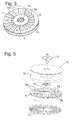
- a second embodiment of the motor is described referring to Figs 5 to 8.
- Components of this motor that have identical counterparts in the motor of the first embodiment have the same reference numerals as these and are not described again.
- the yoke 5 has spokes 7 of identical shape which extend radially to the outside from an inner ring at regular angular intervals.
- An asymmetric magnetic field component is generated in this embodiment by the fact among the coils 9 on the circuit board 8, there is one group formed of three consecutive coils 9b which have a metal core 14, whereas the remaining three coils 9a that form the other group do not.
- These metal cores 14 may simply be fixed to the surface of circuit board 8, e. g. by soldering; preferably and as shown in the cross section of Fig. 6 and the bottom view of Fig. 8, they are fitted into holes that are formed in the circuit board 8, establishing a direct contact between each core 14 and at least one of the spokes 7 of yoke 5.
- the metal cores 14 are also effective to decrease the air gap width in the half of the circuit board 8 occupied by the coils 9b, so that in this half, the ring magnet 13 is subject to a stronger magnetic attraction than in the half bearing the empty coils 9a.
- the asymmetry of the magnetic field causes the shaft 11 to assume a well-defined, slightly tilted orientation.
- Fig. 9 is a bottom view of a circuit board according to a third embodiment of the invention.
- this embodiment instead of a one-part yoke, there is only a number of radial spokes 7 which are not directly interconnected but fixed, e. g. by soldering, to the bottom side of circuit board 8.
- part of the coils formed on the top side of circuit board 8 not shown, have metal cores 14 which extend through holes of the circuit board 8.
- conventional technology for assembling electronic circuits from discrete components may be employed.
- FIG. 11 Another approach for obtaining a magnetic field asymmetry is illustrated by Fig. 11, showing a top view of a circuit board according to a fifth embodiment of the invention.
- the coils 9a in the upper half of the circuit board 8 have a smaller number of windings than the coils 9b of the lower half, so that when the two groups of coils are supplied with identical currents, the magnetic attraction between the ring magnet and the coils 9a will be less than between the ring magnet and coils 9b.
Landscapes
- Engineering & Computer Science (AREA)
- Power Engineering (AREA)
- Permanent Magnet Type Synchronous Machine (AREA)
- Brushless Motors (AREA)
- Windings For Motors And Generators (AREA)
- Iron Core Of Rotating Electric Machines (AREA)
- Magnetic Bearings And Hydrostatic Bearings (AREA)
Priority Applications (9)
| Application Number | Priority Date | Filing Date | Title |
|---|---|---|---|
| EP04029314A EP1670125A1 (fr) | 2004-12-10 | 2004-12-10 | Moteur électrique |
| EP20050300956 EP1670126B1 (fr) | 2004-12-10 | 2005-11-22 | Moteur électrique |
| DE602005027799T DE602005027799D1 (de) | 2004-12-10 | 2005-11-22 | Elektrischer Motor |
| MYPI20055556A MY140682A (en) | 2004-12-10 | 2005-11-29 | Electric motor |
| KR1020050118625A KR101111673B1 (ko) | 2004-12-10 | 2005-12-07 | 전기 모터 |
| US11/298,207 US7382077B2 (en) | 2004-12-10 | 2005-12-08 | Electric motor |
| TW094143496A TWI370606B (en) | 2004-12-10 | 2005-12-09 | Electric motor |
| JP2005356572A JP4801985B2 (ja) | 2004-12-10 | 2005-12-09 | 電気モータ |
| CN2005101314064A CN1787335B (zh) | 2004-12-10 | 2005-12-12 | 电动机 |
Applications Claiming Priority (1)
| Application Number | Priority Date | Filing Date | Title |
|---|---|---|---|
| EP04029314A EP1670125A1 (fr) | 2004-12-10 | 2004-12-10 | Moteur électrique |
Publications (1)
| Publication Number | Publication Date |
|---|---|
| EP1670125A1 true EP1670125A1 (fr) | 2006-06-14 |
Family
ID=34927724
Family Applications (1)
| Application Number | Title | Priority Date | Filing Date |
|---|---|---|---|
| EP04029314A Withdrawn EP1670125A1 (fr) | 2004-12-10 | 2004-12-10 | Moteur électrique |
Country Status (8)
| Country | Link |
|---|---|
| US (1) | US7382077B2 (fr) |
| EP (1) | EP1670125A1 (fr) |
| JP (1) | JP4801985B2 (fr) |
| KR (1) | KR101111673B1 (fr) |
| CN (1) | CN1787335B (fr) |
| DE (1) | DE602005027799D1 (fr) |
| MY (1) | MY140682A (fr) |
| TW (1) | TWI370606B (fr) |
Cited By (1)
| Publication number | Priority date | Publication date | Assignee | Title |
|---|---|---|---|---|
| EP3869675A1 (fr) * | 2020-02-20 | 2021-08-25 | Kohler Co. | Machine électrique de carte de circuit imprimé |
Families Citing this family (11)
| Publication number | Priority date | Publication date | Assignee | Title |
|---|---|---|---|---|
| DE102007002782A1 (de) * | 2007-01-18 | 2008-07-31 | Siemens Ag | Drehantrieb mit geraden Primärteilsegmenten |
| TWI425742B (zh) * | 2008-11-14 | 2014-02-01 | Metal Ind Res & Dev Ct | Integrated in the electronic device of the motor |
| JP2013183494A (ja) * | 2012-02-29 | 2013-09-12 | Sony Corp | 駆動モーター、像ぶれ補正装置及び撮像装置 |
| CN105990977B (zh) * | 2015-02-10 | 2019-08-06 | 苏州捷美电子有限公司 | 一种磁力驱动旋转装置 |
| US10020718B2 (en) * | 2015-05-15 | 2018-07-10 | Saqr Majed Bin Saqr Al Marri | Alternator device |
| US11527933B2 (en) * | 2015-10-02 | 2022-12-13 | E-Circuit Motors, Inc. | Stator and rotor design for periodic torque requirements |
| KR102488442B1 (ko) * | 2016-01-21 | 2023-01-13 | 현대모비스 주식회사 | 모터 장치 |
| US11831211B2 (en) | 2017-06-05 | 2023-11-28 | E-Circuit Motors, Inc. | Stator and rotor design for periodic torque requirements |
| CN109861461A (zh) * | 2017-11-30 | 2019-06-07 | 日本电产株式会社 | 马达以及包含该马达的电气设备 |
| KR101967613B1 (ko) * | 2018-10-04 | 2019-08-19 | 주식회사 유닉스엔지니어링 | 회전형 리니어 액츄에이터 |
| KR20210083341A (ko) * | 2018-11-01 | 2021-07-06 | 이-서킷 모터스 인코퍼레이티드 | 주기적인 회전력 필요조건을 위한 고정자 및 회전자 설계 |
Citations (8)
| Publication number | Priority date | Publication date | Assignee | Title |
|---|---|---|---|---|
| GB2139822A (en) * | 1983-05-03 | 1984-11-14 | Caterpillar Tractor Co | Stator for an electromagnetic machine |
| US4843268A (en) * | 1987-09-17 | 1989-06-27 | Marketing Systems Of The South, Inc. | Asymmetric field electromagnetic motor |
| US5801473A (en) * | 1994-09-20 | 1998-09-01 | Queensland Rail | Open stator axial flux electric motor |
| JPH10243590A (ja) * | 1997-02-26 | 1998-09-11 | Canon Inc | モータ用コイル及びモータ |
| JPH1118348A (ja) * | 1997-06-20 | 1999-01-22 | Matsushita Electric Ind Co Ltd | 面対向型ブラシレスモータ |
| JP2001054270A (ja) * | 1999-08-05 | 2001-02-23 | Sankyo Seiki Mfg Co Ltd | 面対向型モータ |
| JP2002262486A (ja) * | 2001-12-21 | 2002-09-13 | Mitsubishi Electric Corp | 記録媒体駆動用スピンドルモータ |
| EP1365496A2 (fr) * | 2002-05-24 | 2003-11-26 | Mabuchi Motor Co., Ltd | Moteur miniature |
Family Cites Families (12)
| Publication number | Priority date | Publication date | Assignee | Title |
|---|---|---|---|---|
| JPS61202153U (fr) * | 1985-06-05 | 1986-12-18 | ||
| US4733119A (en) | 1986-09-22 | 1988-03-22 | Shicoh Engineering Co., Ltd. | 1-Phase self-starting disk-type brushless motor with cogging-producing element |
| JPH0510547Y2 (fr) | 1986-11-14 | 1993-03-15 | ||
| JP2869064B2 (ja) * | 1987-03-11 | 1999-03-10 | ソニー株式会社 | ディスク駆動装置 |
| JPH0230274A (ja) * | 1988-07-20 | 1990-01-31 | Hitachi Ltd | ダイナミック・ビデオ・フォーカス装置 |
| JPH0458065U (fr) * | 1990-09-26 | 1992-05-19 | ||
| JPH05146129A (ja) * | 1991-11-20 | 1993-06-11 | Canon Inc | モータ |
| JP2992862B2 (ja) * | 1994-06-06 | 1999-12-20 | 株式会社三協精機製作所 | モータ装置 |
| JP3439318B2 (ja) * | 1997-04-18 | 2003-08-25 | 株式会社三協精機製作所 | ブラシレスモータおよびその製造方法 |
| JP4082777B2 (ja) * | 1998-03-17 | 2008-04-30 | 株式会社日本計器製作所 | 偏平ファンモータ |
| CN1469526A (zh) * | 2002-07-19 | 2004-01-21 | 谷立志里科技有限公司 | 具有扁平线圈的组合式定子结构 |
| US6847147B2 (en) | 2003-01-29 | 2005-01-25 | Wavecrest Laboratories, Llc | Dynamoelectric machine having windings that differ in wire gauge and number of winding turns |
-
2004
- 2004-12-10 EP EP04029314A patent/EP1670125A1/fr not_active Withdrawn
-
2005
- 2005-11-22 DE DE602005027799T patent/DE602005027799D1/de active Active
- 2005-11-29 MY MYPI20055556A patent/MY140682A/en unknown
- 2005-12-07 KR KR1020050118625A patent/KR101111673B1/ko not_active IP Right Cessation
- 2005-12-08 US US11/298,207 patent/US7382077B2/en not_active Expired - Fee Related
- 2005-12-09 TW TW094143496A patent/TWI370606B/zh not_active IP Right Cessation
- 2005-12-09 JP JP2005356572A patent/JP4801985B2/ja not_active Expired - Fee Related
- 2005-12-12 CN CN2005101314064A patent/CN1787335B/zh not_active Expired - Fee Related
Patent Citations (8)
| Publication number | Priority date | Publication date | Assignee | Title |
|---|---|---|---|---|
| GB2139822A (en) * | 1983-05-03 | 1984-11-14 | Caterpillar Tractor Co | Stator for an electromagnetic machine |
| US4843268A (en) * | 1987-09-17 | 1989-06-27 | Marketing Systems Of The South, Inc. | Asymmetric field electromagnetic motor |
| US5801473A (en) * | 1994-09-20 | 1998-09-01 | Queensland Rail | Open stator axial flux electric motor |
| JPH10243590A (ja) * | 1997-02-26 | 1998-09-11 | Canon Inc | モータ用コイル及びモータ |
| JPH1118348A (ja) * | 1997-06-20 | 1999-01-22 | Matsushita Electric Ind Co Ltd | 面対向型ブラシレスモータ |
| JP2001054270A (ja) * | 1999-08-05 | 2001-02-23 | Sankyo Seiki Mfg Co Ltd | 面対向型モータ |
| JP2002262486A (ja) * | 2001-12-21 | 2002-09-13 | Mitsubishi Electric Corp | 記録媒体駆動用スピンドルモータ |
| EP1365496A2 (fr) * | 2002-05-24 | 2003-11-26 | Mabuchi Motor Co., Ltd | Moteur miniature |
Non-Patent Citations (4)
| Title |
|---|
| PATENT ABSTRACTS OF JAPAN vol. 1998, no. 14 31 December 1998 (1998-12-31) * |
| PATENT ABSTRACTS OF JAPAN vol. 1999, no. 04 30 April 1999 (1999-04-30) * |
| PATENT ABSTRACTS OF JAPAN vol. 2000, no. 19 5 June 2001 (2001-06-05) * |
| PATENT ABSTRACTS OF JAPAN vol. 2003, no. 01 14 January 2003 (2003-01-14) * |
Cited By (2)
| Publication number | Priority date | Publication date | Assignee | Title |
|---|---|---|---|---|
| EP3869675A1 (fr) * | 2020-02-20 | 2021-08-25 | Kohler Co. | Machine électrique de carte de circuit imprimé |
| US11799342B2 (en) | 2020-02-20 | 2023-10-24 | Kohler Co. | Printed circuit board electrical machine |
Also Published As
| Publication number | Publication date |
|---|---|
| DE602005027799D1 (de) | 2011-06-16 |
| US7382077B2 (en) | 2008-06-03 |
| KR20060065506A (ko) | 2006-06-14 |
| US20060125342A1 (en) | 2006-06-15 |
| TWI370606B (en) | 2012-08-11 |
| JP4801985B2 (ja) | 2011-10-26 |
| JP2006174696A (ja) | 2006-06-29 |
| CN1787335A (zh) | 2006-06-14 |
| TW200625759A (en) | 2006-07-16 |
| KR101111673B1 (ko) | 2012-02-17 |
| MY140682A (en) | 2010-01-15 |
| CN1787335B (zh) | 2010-05-12 |
Similar Documents
| Publication | Publication Date | Title |
|---|---|---|
| US7382077B2 (en) | Electric motor | |
| JP4687871B2 (ja) | アキシャルギャップ型電動機 | |
| US7012346B2 (en) | Low profile d.c. brushless motor for an impeller mechanism or the like | |
| US10047754B2 (en) | Brushless motor and fan using the motor | |
| JPH10513338A (ja) | 最小の正味径方向力および低いコギングトルクを伴う d.c.ブラシレスモータ | |
| US10340773B2 (en) | Brushless motor having an outer rotor and an annular separation plate between the drive magnet and the position detection magnet | |
| EP0393266B1 (fr) | Moteur de mandrin pour une unité de disque | |
| EP1670126B1 (fr) | Moteur électrique | |
| US4839551A (en) | Brushless motor structure enabling accurate relative positioning of rotor and stator coils | |
| US20080018188A1 (en) | Disk storage device with brushless dc drive motor and slide bearing assembly | |
| JP2000270514A (ja) | モータ、モータの製造方法、及び回転体装置 | |
| JPH05344701A (ja) | ブラシレスモータ | |
| JP2002345204A (ja) | スピンドルモータおよびその製造方法 | |
| JP2003219600A (ja) | アキシャルギャップ型電動機 | |
| KR100896519B1 (ko) | 전자석 제조방법 | |
| US20090001836A1 (en) | Spindle Motor | |
| KR20130095110A (ko) | 모터용 마그네트의 착자 구조 | |
| JP2011070755A (ja) | モーター及びディスク駆動装置 | |
| JP2005027438A (ja) | 薄型モータ | |
| JPH07336982A (ja) | モータ装置 | |
| JPH04244767A (ja) | 着磁ヨーク装置 | |
| EP0433037A1 (fr) | Moteur axe et unité de disque pourvue de celui-ci | |
| JP2006060993A (ja) | ディスク駆動装置 | |
| JPH06113495A (ja) | アキシャルギャップ形モータ | |
| KR20000044157A (ko) | 단상의 디스크 타입의 팬 모터 |
Legal Events
| Date | Code | Title | Description |
|---|---|---|---|
| PUAI | Public reference made under article 153(3) epc to a published international application that has entered the european phase |
Free format text: ORIGINAL CODE: 0009012 |
|
| AK | Designated contracting states |
Kind code of ref document: A1 Designated state(s): AT BE BG CH CY CZ DE DK EE ES FI FR GB GR HU IE IS IT LI LT LU MC NL PL PT RO SE SI SK TR |
|
| AX | Request for extension of the european patent |
Extension state: AL BA HR LV MK YU |
|
| AKX | Designation fees paid | ||
| STAA | Information on the status of an ep patent application or granted ep patent |
Free format text: STATUS: THE APPLICATION IS DEEMED TO BE WITHDRAWN |
|
| 18D | Application deemed to be withdrawn |
Effective date: 20061215 |
|
| REG | Reference to a national code |
Ref country code: DE Ref legal event code: 8566 |