EP1669736B1 - Dispositif de mesure de flux de concentration de gaz - Google Patents
Dispositif de mesure de flux de concentration de gaz Download PDFInfo
- Publication number
- EP1669736B1 EP1669736B1 EP20040788226 EP04788226A EP1669736B1 EP 1669736 B1 EP1669736 B1 EP 1669736B1 EP 20040788226 EP20040788226 EP 20040788226 EP 04788226 A EP04788226 A EP 04788226A EP 1669736 B1 EP1669736 B1 EP 1669736B1
- Authority
- EP
- European Patent Office
- Prior art keywords
- signal
- measuring
- modulation
- wavelength
- gas
- Prior art date
- Legal status (The legal status is an assumption and is not a legal conclusion. Google has not performed a legal analysis and makes no representation as to the accuracy of the status listed.)
- Expired - Fee Related
Links
- 230000004907 flux Effects 0.000 title claims abstract description 158
- 238000005259 measurement Methods 0.000 claims abstract description 190
- 230000003287 optical effect Effects 0.000 claims abstract description 50
- 238000004458 analytical method Methods 0.000 claims abstract description 14
- 230000010287 polarization Effects 0.000 claims description 88
- 238000010521 absorption reaction Methods 0.000 claims description 19
- 230000010355 oscillation Effects 0.000 claims description 10
- 239000002245 particle Substances 0.000 claims description 9
- 230000001360 synchronised effect Effects 0.000 claims description 9
- 238000004364 calculation method Methods 0.000 claims description 8
- 239000007787 solid Substances 0.000 claims description 8
- 230000008859 change Effects 0.000 claims description 7
- 230000005540 biological transmission Effects 0.000 claims description 4
- 238000011144 upstream manufacturing Methods 0.000 claims description 4
- 230000004044 response Effects 0.000 abstract description 3
- 239000007789 gas Substances 0.000 description 157
- 238000000041 tunable diode laser absorption spectroscopy Methods 0.000 description 43
- 238000000034 method Methods 0.000 description 42
- 239000004065 semiconductor Substances 0.000 description 29
- 238000010276 construction Methods 0.000 description 27
- 238000010586 diagram Methods 0.000 description 22
- 230000006870 function Effects 0.000 description 16
- VNWKTOKETHGBQD-UHFFFAOYSA-N methane Chemical compound C VNWKTOKETHGBQD-UHFFFAOYSA-N 0.000 description 16
- 238000005516 engineering process Methods 0.000 description 13
- 238000005070 sampling Methods 0.000 description 11
- 239000005431 greenhouse gas Substances 0.000 description 9
- 230000008054 signal transmission Effects 0.000 description 8
- 238000000862 absorption spectrum Methods 0.000 description 7
- 230000007246 mechanism Effects 0.000 description 7
- 238000002347 injection Methods 0.000 description 6
- 239000007924 injection Substances 0.000 description 6
- 241000196324 Embryophyta Species 0.000 description 5
- 238000004891 communication Methods 0.000 description 5
- 238000011835 investigation Methods 0.000 description 5
- 230000035945 sensitivity Effects 0.000 description 5
- 238000012544 monitoring process Methods 0.000 description 4
- 239000013307 optical fiber Substances 0.000 description 4
- 239000000126 substance Substances 0.000 description 4
- 241000209094 Oryza Species 0.000 description 3
- 235000007164 Oryza sativa Nutrition 0.000 description 3
- 230000021715 photosynthesis, light harvesting Effects 0.000 description 3
- 230000003252 repetitive effect Effects 0.000 description 3
- 235000009566 rice Nutrition 0.000 description 3
- 238000006243 chemical reaction Methods 0.000 description 2
- 238000010790 dilution Methods 0.000 description 2
- 239000012895 dilution Substances 0.000 description 2
- 230000000694 effects Effects 0.000 description 2
- 230000001681 protective effect Effects 0.000 description 2
- 230000003595 spectral effect Effects 0.000 description 2
- 238000001228 spectrum Methods 0.000 description 2
- 238000010408 sweeping Methods 0.000 description 2
- 235000018185 Betula X alpestris Nutrition 0.000 description 1
- 235000018212 Betula X uliginosa Nutrition 0.000 description 1
- SVPXDRXYRYOSEX-UHFFFAOYSA-N bentoquatam Chemical compound O.O=[Si]=O.O=[Al]O[Al]=O SVPXDRXYRYOSEX-UHFFFAOYSA-N 0.000 description 1
- 238000009529 body temperature measurement Methods 0.000 description 1
- 238000012790 confirmation Methods 0.000 description 1
- 238000007796 conventional method Methods 0.000 description 1
- 238000012937 correction Methods 0.000 description 1
- 238000001514 detection method Methods 0.000 description 1
- 238000009792 diffusion process Methods 0.000 description 1
- 239000000428 dust Substances 0.000 description 1
- 230000002708 enhancing effect Effects 0.000 description 1
- 230000007613 environmental effect Effects 0.000 description 1
- 230000014509 gene expression Effects 0.000 description 1
- 238000001307 laser spectroscopy Methods 0.000 description 1
- 239000010410 layer Substances 0.000 description 1
- 239000002184 metal Substances 0.000 description 1
- 238000010606 normalization Methods 0.000 description 1
- 230000029553 photosynthesis Effects 0.000 description 1
- 238000010672 photosynthesis Methods 0.000 description 1
- 238000002203 pretreatment Methods 0.000 description 1
- 230000008569 process Effects 0.000 description 1
- 238000000275 quality assurance Methods 0.000 description 1
- 230000009467 reduction Effects 0.000 description 1
- 238000011160 research Methods 0.000 description 1
- 238000011896 sensitive detection Methods 0.000 description 1
- 241000894007 species Species 0.000 description 1
- 239000002344 surface layer Substances 0.000 description 1
- 239000013598 vector Substances 0.000 description 1
- 238000010792 warming Methods 0.000 description 1
Images


Classifications
-
- G—PHYSICS
- G01—MEASURING; TESTING
- G01J—MEASUREMENT OF INTENSITY, VELOCITY, SPECTRAL CONTENT, POLARISATION, PHASE OR PULSE CHARACTERISTICS OF INFRARED, VISIBLE OR ULTRAVIOLET LIGHT; COLORIMETRY; RADIATION PYROMETRY
- G01J3/00—Spectrometry; Spectrophotometry; Monochromators; Measuring colours
- G01J3/28—Investigating the spectrum
- G01J3/42—Absorption spectrometry; Double beam spectrometry; Flicker spectrometry; Reflection spectrometry
- G01J3/433—Modulation spectrometry; Derivative spectrometry
-
- G—PHYSICS
- G01—MEASURING; TESTING
- G01N—INVESTIGATING OR ANALYSING MATERIALS BY DETERMINING THEIR CHEMICAL OR PHYSICAL PROPERTIES
- G01N21/00—Investigating or analysing materials by the use of optical means, i.e. using sub-millimetre waves, infrared, visible or ultraviolet light
- G01N21/17—Systems in which incident light is modified in accordance with the properties of the material investigated
- G01N21/21—Polarisation-affecting properties
-
- G—PHYSICS
- G01—MEASURING; TESTING
- G01N—INVESTIGATING OR ANALYSING MATERIALS BY DETERMINING THEIR CHEMICAL OR PHYSICAL PROPERTIES
- G01N21/00—Investigating or analysing materials by the use of optical means, i.e. using sub-millimetre waves, infrared, visible or ultraviolet light
- G01N21/17—Systems in which incident light is modified in accordance with the properties of the material investigated
- G01N21/25—Colour; Spectral properties, i.e. comparison of effect of material on the light at two or more different wavelengths or wavelength bands
- G01N21/31—Investigating relative effect of material at wavelengths characteristic of specific elements or molecules, e.g. atomic absorption spectrometry
-
- G—PHYSICS
- G01—MEASURING; TESTING
- G01N—INVESTIGATING OR ANALYSING MATERIALS BY DETERMINING THEIR CHEMICAL OR PHYSICAL PROPERTIES
- G01N15/00—Investigating characteristics of particles; Investigating permeability, pore-volume or surface-area of porous materials
- G01N15/06—Investigating concentration of particle suspensions
Definitions
- the present invention relates to a gas flux measuring device used for such purposes as an assessment of CO 2 absorption quantity by a forest, an environment investigation, such as an investigation of generation quantity of greenhouse gases (GHG) coming out of the ground, and a detection of gas leakage from CO 2 underground disposal plants, gas storage facilities, pipelines, etc.
- GHG greenhouse gases
- FIG. 15A A most simplified method to grasp the gas discharge (flux) quantity per unit area from the ground will be described with reference to Fig. 15A .
- a container 101 having a small hole 102 is placed so as to cover the ground 100a and a concentration of a measuring object gas of the initial state in the container 101 is measured. After passing of a predetermined time, the gas concentration is again measured. Thus, by the concentration difference and ground covering area/volume of the container, the gas flux quantity can be assessed.
- numeral 104 designates a gas collector and numeral 106 an analyzer.
- an observation tower 91 is installed in a forest 99.
- a current meter 51 having a good time-wise responsibility (response ability) and a CO 2 densitometer 93 are mounted on the tower 91 so that an atmospheric air observation is carried out. Results of the measurements are analyzed by the eddy correlation method to thereby obtain the forest CO 2 flux quantity (that is, the CO 2 absorption quantity by the forest).
- the inventors here have heretofore reported continuous observations of CO 2 flux, as mentioned in Non-patent Document 1 below.
- an ultrasonic current meter with a very high time-wise responsibility is generally used.
- CO 2 concentration measurement while it is usual to use a closed path type CO 2 densitometer 96 using a sampling pipe 95, an open path type CO 2 meter, as shown by the CO 2 densitometer 93, with a high time-wise responsibility using an infrared ray source (the measuring length is 1 m or less) also has recently begun to be used.
- numeral 90 designates an observation room and numeral 19 an analyzer.
- a regional momentum flux measuring technology using a laser has been developed and application thereof to the forest measurement is being proceeded, wherein the regional momentum flux is defined as vertical directional transport properties of an atmospheric air mass (average density) being multiplied by a horizontal directional velocity component.
- This measuring technology by the scintillation method will be described.
- two observation towers 91, 92, being kept away from each other, are installed in the forest 99.
- a scintillation measuring unit 70 is mounted in a light source part 111 provided on one of the towers 91 and two laser beams are radiated therefrom so as to be transmitted above the forest 99 and received by a light receiving part 112 provided on the other of the towers 92. At the light receiving part 112, time-wise changes of respective laser transmission factors (scintillation) are measured.
- numeral 90 designates an observation room
- numeral 121 a demodulator
- numeral 122 an analyzer.
- the basic construction of this prior art system comprises, as shown in Fig. 15D , a pair of scintillation measuring laser oscillators 113, 114 on the tower 91, a pair of light receivers 115, 116 on the tower 92 and the analyzer 122 provided in a measuring room 123.
- Two laser beams 113a, 114a transmitted through a measuring region 100 are received by the light receivers 115, 116, respectively, so that received light signals S101, S102 are sent to the analyzer 122.
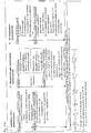
- an analysis 132 of variance and covariance is first carried out in order to grasp an atmospheric turbulence state on the optical path (that is, an optical path turbulence analysis 131) and then a dissipation factor ⁇ of kinetic energy or heat is obtained by an analyzing method 133 using the Monin-Obukhov similarity law (herein referred to as the MOS law). Also, a momentum flux or sensible heat flux 134 (including a latent heat flux also according to the case) is obtained.
- the atmospheric turbulence state (that is, in this case, the atmospheric density turbulences or the secondary density structure function Dn 2 corresponding to time-wise changes of the laser transmission factor) is measured and, based on the MOS law, the measurement results are sequentially analyzed (that is, the atmospheric turbulence state ⁇ kinetic energy spectra ⁇ energy dissipation factors) so that the momentum flux is obtained.
- an infrared ray source having a large oscillation width is used as the light source.
- the concomitant gas especially by H 2 O.
- the measuring range is limited to the region in the vicinity of the sampling position.
- the measuring length thereof is at most 1 m or less.
- the tunable diode laser absorption spectroscopy teaching is used for micro meteorological flux measurement i.e. eddy covariance determinations representing turbulence in the atmosphere in which the vertical velocity of the gas species is determined e.g by an ultrasonic anemometer.
- the air motion and gas concentration data is is processed by a computer system.
- the 7.8 micron spectral region covers the strong absorption bands of methane.
- a single mode emission at a selected absorption line of methane is selected.
- the laser is subject to high frequency FM modulation in the "rf' region allowing selective and fast scanning over the absorption line.
- the modulation electronics of Fig. 2(a) comprises a section which provides the required rf laser modulation.
- the laser beam is split into a sample and a reference path and the detector signals are fed into a phase sensitive detection electronics which functions as high frequency lock in amplifier. Both sample and reference signals are digitised and further processed by use of digital filter and line locking, normalisation and calibration procedures.
- the reference beam passes through a reference cell to provide a signal from the spectral feature under investigation which is used for line locking and on-line drift correction according to which any drift in wavelength of laser output is detected and compensated for by changes in temperature of current.
- the corrected signals are fed into a digital filter routine that removes the background and reference the signal to a previously stored calibration signal as show in Fig. 2(c).
- a dust filter is mounted at the inlet port to protect the gas system from pollution. Fast examination of the wind vectors is performed by an ultrasonic anemometer and the speed of sound was measured to derive the virtual temperature. An eddy correlation process is used to calculate the turbulent vertical flux by using the time series of concentration perturbations and the velocity perturbations.
- wind direction As discussed with reference to Fig. 5 wind direction, wind speed, temperature pressure and humidity were recorded together with the spectroscopic gas sensor data to generate a complete data set for micro - meteorological analysis. Three wind components (two horizontal and one vertical) were obtained to determine horizontal wind speeds and directions -the turbulent flux was determined as shown in Fig. 6(f), the methane concentration in Fig. 6(h).
- TDLAS tunable diode laser absorption spectroscopy
- the TDLAS is used such that (a) as a simple gas concentration measuring technology, the TDLAS combined with a current meter having a high time-wise responsibility is applied to the flux measurements or (b) a laser beam of which wavelength or polarization plane is controllable so as to be used for the gas concentration measurements by the TDLAS is applied to the flux measurements, such gas flux measurements as can effectively solve the above-mentioned prior art problems will become possible.
- a laser beam of which wavelength or polarization plane is controllable so as to be used for the gas concentration measurements by the TDLAS is applied to the flux measurements
- gas flux measurements as can effectively solve the above-mentioned prior art problems will become possible.
- the term “momentum flux” means vertical directional transport properties of a horizontal directional momentum of the entire gas existing in the measuring region, wherein the horizontal directional momentum is, for example, an atmospheric air average density being multiplied by a horizontal directional wind velocity.
- the term “gas flux” means vertical directional transport properties of only the measuring object gas in the measuring region.
- a regional gas concentration measuring device by the wavelength modulation TDLAS and a regional momentum flux measuring device by the scintillation method are combined and respective measurement results thereof are incorporated together based on the MOS law and thereby the regional gas flux measurement is enabled.
- the wavelength modulation TDLAS is added with the function of the scintillation method and thereby the regional gas flux measuring device by a single unit is enabled.
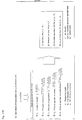
- Figs. 16A and 16B the steps to obtain the momentum flux by the scintillation method are shown in Figs. 16A and 16B .
- the basic principle for obtaining the momentum flux by the scintillation method is described in detail in the Non-patent Document 2. While the expressions of the steps shown in Figs. 16A and 16B are not necessarily the same as those mentioned in the Non-patent Document 2, the basic concept thereof is the same.
- the laser beam When the laser beam is transmitted through the measuring region, if the gas in that region (the atmospheric air) is turbulent, the laser beam is slightly bent by the changes of the refractive index and thereby glittering of the laser beam (laser scintillation) can be measured at the light receiving part.
- this glittering is measured at two light receiving parts and, by the variance (B1, B2) and covariance (B) of respective data, the minimum unit (internal scale) Lo, momentum energy dissipation rate ⁇ and degree of changes of the air density p (density structure function) Cn 2 of the atmospheric turbulences are obtained.
- the internal scale Lo, momentum energy dissipation rate ⁇ and density structure function Cn 2 are obtained based on the result of the laser scintillation measurements.
- the concentration g of the measuring object gas in the measuring region is obtained by the TDLAS.
- the degree of changes of the measuring object gas in the measuring region is obtained.
- the temperature structure function Cr 2 is obtained.
- the present invention not only a gas flux measuring technology that can solve the prior art problem and enhance the measuring accuracy is realized but also a real time measuring of the regional gas flux that has so far been impossible only by the combination of the conventional technologies becomes possible.
- the environmental measurements or leakage monitoring using the present invention can realize a large reduction of work or cost and finally upgrading of the forest administration or safety administration of various industrial plants can be realized.
- the polarization plane of the laser beam is changed over between the vertical polarization and the horizontal polarization. Therefore, the number of the laser oscillators and the number of the light receivers can be reduced.
- the wavelength modulation TDLAS measurement is an optical measurement
- the gas sampling or pretreatment as conventionally needed becomes unnecessary and the regional gas flux measurement that has been impossible by the combination of conventional technologies becomes possible.
- a real time measurement can be realized because of the excellent time-wise responsibility.
- the concentration measuring sensitivity by the wavelength modulation is largely enhanced and even if the measuring time constant is reduced (or the time-wise responsibility is enhanced), measurement of the gas flux with a sufficient sensitivity becomes possible.
- the wavelength modulation is carried out by plural steps and thereby the enhancement of the measurement stability is verified.
- the wavelength modulation TDLAS is of the optical measurement using the laser, the real time measurement of the regional gas concentration that has been very difficult by the conventional gas concentration measuring technology becomes possible.
- this wavelength modulation TDLAS technology with the regional momentum flux measuring technology by the scintillation method, a real time measurement of the regional gas flux becomes possible.
- a gas concentration measuring device 10 comprises a light source part 2, light receiver 3 for measuring purpose, direct current component detector 4 for measuring purpose, direct current component detector 12 for reference purpose, wavelength modulation demodulator 5 for concentration measuring purpose, wavelength modulation controller 6, wavelength modulation demodulator 7 for concentration calibrating purpose, wavelength modulation demodulator 8 for laser wavelength fixing signal purpose, adder 9, LD controller (laser output controller) 11, A/D converter 13 and computer 14 as an analyzing part.
- the light source part 2 has its outer periphery covered by an optical system container 2a having an excellent weather resistance.
- a semi-conductor laser beam source 21 for reference purpose receiving the laser beam from the reference cell 25.
- the semi-conductor laser beam source 21 is provided within an LD module together with a Peltier element that carries out a temperature adjustment of the laser element.
- the semi-conductor laser element is connected to a drive circuit of the LD controller 11 so that the temperature and electric current thereof are controlled.
- An oscillation signal S1 sent to the laser beam source 21 from the LD controller 11 is applied with a feedback control by a signal S13 from the adder 9.
- the light source is described as the laser beam source 21 using the semi-conductor laser element
- the light source of the present disclosure is not limited to the semi-conductor laser element but all other laser oscillators that are capable of wavelength modulation can also be employed, or even in the case of light or electromagnetic wave devices other than the laser, if they are capable of wavelength modulation, they are all applicable.
- the LD controller 11 may be either of a manual control or of an external control.
- a temperature indicator T1 and pressure indicator P1 are provided in a measuring region 100 so that a measured temperature signal S2 and measured pressure signal S3 are sent to the computer 14 as the analyzing part via the A/D converter 13.
- the light receiver 3 for measuring purpose as a first light receiver is arranged having its optical axis coincide with an optical axis of the light source part 2 so as to receive the laser beam transmitted through the measuring region 100 that includes the measuring object gas and particles as objects to be measured.
- the direct current component detector 4 for measuring purpose as a first direct current component detector and the wavelength modulation demodulator 5 for concentration measuring purpose as a first wavelength modulation demodulator are provided downstream of the first light receiver 3.
- the first direct current component detector 4 removes an alternating current component as a modulation signal out of a signal S4 put out from the first light receiver 3 and puts out a direct current component signal S5 of a received light strength into the computer 14.
- the first wavelength modulation demodulator 5 Based on a reference signal S10 from the wavelength modulation controller 6, the first wavelength modulation demodulator 5 detects an even number order harmonic component of the wavelength modulation signal added to the laser beam out of the signal S4 put out from the first light receiver 3 and puts out a signal S6 in proportion to the concentration of the measuring object gas in the measuring region 100.
- the wavelength modulation controller 6 is provided upstream of the first wavelength modulation demodulator 5, the wavelength modulation demodulator 7 for concentration calibrating purpose as a second wavelength modulation demodulator and the adder 9 and puts out a wavelength modulation reference signal S10 to the first and second wavelength modulation demodulators 5, 7, respectively, and also puts out a wavelength modulation signal S11 to the adder 9.
- the measuring object gas CO 2 gas, for example
- the reference cell 25 the measuring object gas (CO 2 gas, for example) of which concentration is known is enclosed and the reference cell 25 is arranged at such a position that the laser beam that has been distributed by the optical system (the half mirror 22 and mirror 24) so as not to be directed to the measuring region 100 is transmitted through the enclosed gas.
- the light receiver 26 for reference purpose as a second light receiver, provided downstream of the reference cell 25, receives the laser beam that has been transmitted through the enclosed gas in the reference cell 25 and puts out a signal 27 corresponding to a received light strength thereof into the direct current component detector 12 for reference purpose as a second direct current component detector.
- the second direct current component detector 12 removes an alternating current component as a modulation signal out of a signal S7 put out from the second light receiver 26 and puts out a direct current component signal S8 of the received light strength into the computer 14.
- the wavelength modulation demodulator 7 for concentration calibrating purpose as a second wavelength modulation demodulator detects an even number order harmonic component of the wavelength modulation signal added to the laser beam out of the signal S7 put out from the second light receiver 26 and puts out a signal S9 in proportion to the concentration of the enclosed gas in the reference cell 25 into the computer 14.
- the wavelength modulation demodulator 8 for laser wavelength fixing signal purpose as a third wavelength modulation demodulator detects an odd number order harmonic component of the wavelength modulation signal added to the laser beam out of the signal S7 put out from the second light receiver 26 and puts out a laser wavelength fixing signal S 12 as a standard signal for fixing the laser wavelength to an absorption wavelength of the measuring object gas into the adder 9.
- the computer 14 calculates the gas concentration and solid particle concentration in the measuring region 100 and the result of the calculation is recorded as well as is put out to be displayed on a display screen.
- the adder 9 adds the laser wavelength fixing signal S 12 from the third wavelength modulation demodulator 8 to the modulation signal S11 from the wavelength modulation controller 6 and puts out an addition signal S 13 thereof into the LD controller (laser output controller) 11 as an external control signal.
- the calculation of the gas concentration is carried out as follows.
- a standard gas of which gas concentration is known is previously enclosed or caused to flow in the reference cell 25 under a predetermined pressure.
- the data of the known gas concentration in the reference cell 25, known optical length of the reference cell 25 and known optical length of the measuring region 100 are inputted into the computer 14 as the analyzing part.
- the computer 14 calls a predetermined equation from the memory and applies the three input data to respective parameters of the equation. Thereby, the gas concentration is obtained by calculation.
- the obtained values of the gas concentration are continuously recorded and, at the same time, the time-wise changing state thereof is put out to be displayed on a display screen.
- the device of the present disclosure comprises the part that is in charge of the flux measurement as follows.
- Fig. 2 is a block diagram showing an entire construction of a gas flux measuring device 10A according to the present disclosure as one example. It is to be noted that as to the portions of the present gas flux measuring device 10A same as those of the above gas concentration measuring device 10, repetitive descriptions will be omitted.
- a light source part 2A of the gas flux measuring device 10A comprises a laser beam source 21A as a second light source in addition to the semi-conductor laser beam source 21 as a first light source.
- An optical system container 2a has two optical windows 23a, 23b, arranged side by side, so that an oscillated laser beam of the first light source 21 is radiated to the measuring region 100 through the one optical window 23a and an oscillated laser beam of the second light source 21A is radiated to the measuring region 100 through the other optical window 23b.
- the first and second light sources 21, 21A are so positioned relative to each other that optical axes of the two laser beams become substantially parallel with each other.
- a light receiver 3A for measuring purpose comprises a first light receiver 31 and second light receiver 32.
- the first light receiver 31 receives the laser beam oscillated from the first light source 21 and puts out a signal S41 thereof into a first direct current component detector 41.
- the second light receiver 32 receives the laser beam oscillated from the second light source 21A and puts out a signal S42 thereof into a third direct current component detector 42.
- the third direct current component detector 42 removes an alternating current component as a modulation signal out of the received light signal S42 and puts out a signal S52 as an atmospheric turbulence component signal into the computer 14 as the analyzing part.
- the first direct current component detector 41 removes an alternating current component as a modulation signal out of the received light signal S41 and puts out a signal S51 as a measuring part received light strength signal into the computer 14.
- the wavelength modulation demodulator 5 for concentration measuring purpose detects an even number order harmonic component of the wavelength modulation signal added to the laser beam out of the signal S41 put out from the first light receiver 31 and puts out a signal S61 in proportion to the concentration of the measuring object gas in the measuring region 100.
- the computer 14 calculates the gas concentration and solid particle concentration in the measuring region 100 based on the MOS law and, at the same time, calculates the momentum flux in the measuring region 100. The result of these calculations is continuously recorded as well as is put out to be displayed on a display screen.
- numeral 99 designates a forest in the measuring region 100.
- Fig. 3 is a block diagram showing an entire construction of a gas flux measuring device 10B according to the present invention as another embodiment. It is to be noted that as to the portions of the present gas flux measuring device 10B same as those of the above devices 10, 10A, repetitive descriptions will be omitted.
- a light source part 2B of the gas flux measuring device 10B comprises a polarization plane rotating device 27 having a polarization angle fixed to 90° and a laser beam distributing optical system including a first half mirror 22a and second half mirror 22b as well as two mirrors 24a, 24b.
- the first and second half mirrors 22a, 22b are provided between the light source 21 as the semi-conductor laser beam source and the polarization plane rotating device 27.
- the first half mirror 22a reflects a portion of the laser beam oscillated from the light source 21 to be distributed to the reference cell 25 via the mirror 24a.
- the second half mirror 22b reflects a portion of the laser beam transmitted through the first half mirror 22a so that this reflected laser beam is radiated to the measuring region 100 via the mirror 24b and the first optical window 23a.
- the second half mirror 22b transmits a portion of the laser beam transmitted through the first half mirror 22a to be distributed to the polarization plane rotating device 27.
- the polarization plane rotating device 27 contains a Faraday rotator that rotates a vertically polarized light by an angle of 90° to be alternately converted to a horizontally polarized light.
- the laser beam applied with the polarization plane modulation by the polarization plane rotating device 27 is radiated to the measuring region 100 from the second optical window 23b.
- the optical system (22a, 22b, 24a and 24b) and the polarization plane rotating device 27 are so positioned relative to each other that optical axes of the two laser beams become substantially parallel with each other.
- a light receiver 3B for measuring purpose comprises a first light receiver 31 and second light receiver 32.
- the first light receiver 31 receives the oscillated laser beam and puts out a signal S41 thereof into a first direct current component detector 41.
- the second light receiver 32 receives the laser beam applied with the polarization plane modulation and puts out a signal S42 thereof into a third direct current component detector 42.
- the third direct current component detector 42 removes an alternating current component as a modulation signal out of the received light signal 42 and puts out an atmospheric turbulence component signal S52 into the computer 14 as the analyzing part.
- the first direct current component detector 41 receives an alternating current component as a modulation signal out of the received light signal S41 and puts out a signal S51 as a measuring part received light strength signal into the computer 14.
- the wavelength modulation demodulator 5 for concentration measuring purpose detects an even number order harmonic component of the wavelength modulation signal added to the laser beam out of the signal S41 put out from the first light receiver 31 and puts out a signal S61 in proportion to the concentration of the measuring object gas in the measuring region 100.
- the computer 14 calculates the gas concentration and solid particle concentration in the measuring region 100 based on the MOS law and, at the same time, calculates the momentum flux in the measuring region 100. The result of these calculations is continuously recorded as well as is put out to be displayed on a display screen.
- Fig. 4 is a block diagram showing an entire construction of a gas flux measuring device 10C according to the present invention as still another embodiment. It is to be noted that as to the portions of the present gas flux measuring device 10C same as those of the above devices 10, 10A, 10B, repetitive descriptions will be omitted.
- a light source part 2C of the gas flux measuring device 10C comprises an externally controlled polarization plane (modulation) rotating device 27A having a polarization angle of 0°/90°.
- the half mirror 22a reflects a portion of the laser beam oscillated from the single light source (the semi-conductor laser beam source) 21 to be distributed to the reference cell 25 via the mirror 24. At the same time, the half mirror 22a transmits a portion of the oscillated laser beam to be distributed to the externally controlled polarization plane rotating device 27A.
- the externally controlled polarization plane rotating device 27A is inputted with a modulation control signal S 14 from a polarization plane modulation controller 15 provided outside so that change-overs between the vertically polarized light (0°) and the horizontally polarized light (90°) are carried out with a predetermined timing by the Faraday rotator.
- the laser beam applied with the polarization plane modulation by the externally controlled polarization plane rotating device 27A is radiated toward the measuring region 100 from the optical window 23 to be received by a light receiver 3C for measuring purpose.
- the single laser beam oscillated from the single light source 21 is applied with a timing control by which the vertically polarized light and the horizontally polarized light are alternately changed over and thereby the flux measurement and the concentration measurement are carried out at the same time.
- the light receiver 3C puts out the received light signal S4 into a first polarization plane modulation demodulator 17a, second polarization plane modulation demodulator 17b and the first wavelength modulation demodulator 5, respectively.
- the polarization plane modulation controller 15 puts out the modulation control signal S 14 into the externally controlled polarization plane rotating device 27A and, at the same time, puts out a polarization plane modulation reference signal S 15 into a signal phase converter 16, the first polarization plane modulation demodulator 17a and a third polarization plane modulation demodulator 18, respectively.
- the signal phase converter 16 Upon receiving the polarization plane modulation reference signal S 15 from the polarization plane modulation controller 15, the signal phase converter 16 converts a phase of the signal and puts out a phase conversion signal S16 thereof into the second polarization plane modulation demodulator 17b.
- the first wavelength modulation demodulator 5 Based on the reference signal S10 from the wavelength modulation controller 6, the first wavelength modulation demodulator 5 detects an even number order harmonic component of the wavelength modulation signal added to the laser beam out of the received light signal S4 and puts out a signal S6 in proportion to the concentration of the measuring object gas in the measuring region into the third polarization plane modulation demodulator 18.
- the first polarization plane modulation demodulator 17a Upon receiving the polarization plane modulation reference signal S 15 from the polarization plane modulation controller 15, the first polarization plane modulation demodulator 17a detects a signal synchronized with the polarization plane modulation out of the received light signal S4 and puts out a signal S 18 in proportion to the received light strength of the vertically polarized laser beam that has been transmitted through the measuring region 100 as a measuring part laser beam absorption quantity signal into the computer 14 as the analyzing part.
- the second polarization plane modulation demodulator 17b Upon receiving the phase conversion signal S16 from the signal phase converter 16, the second polarization plane modulation demodulator 17b detects a signal synchronized with the polarization plane modulation out of the received light signal S4 and puts out a signal S 17 in proportion to the received light strength of the horizontally polarized laser beam that has been transmitted through the measuring region as a measuring part laser beam absorption quantity signal into the computer 14.
- the third polarization plane modulation demodulator 18 Upon receiving the polarization plane modulation reference signal S 15 from the polarization plane modulation controller 15, the third polarization plane modulation demodulator 18 detects a signal S62 in proportion to the strength of the received light signal S4 of the laser beam that has been transmitted through the measuring region 100 as a concentration measurement signal and puts it out into the computer 14.
- a frequency ⁇ 2 of the polarization plane modulation reference signal S 15 (100 Hz, for example) is set sufficiently lower than a frequency ⁇ 1 of the wavelength modulation reference signal S10 (10 KHz, for example).
- the frequency ⁇ 2 of the polarization plane modulation reference signal S 15 (1 MHz, for example) is set sufficiently higher than the frequency ⁇ 1 of the wavelength modulation reference signal S10 (10 KHz).
- the computer 14 calculates the gas concentration and solid particle concentration in the measuring region 100 based on the MOS law and, at the same time, calculates the momentum flux in the measuring region 100. The result of these calculations is continuously recorded as well as is put out to be displayed on a display screen.
- a gas flux measuring device comprising a combination of a TDLAS type gas concentration measuring device and an ultrasonic current meter according to the present invention as still another embodiment
- a CO 2 flux and concentration thereof are measured on a forest observation tower and the result will be described next as Measurement 1. It is to be noted that as to the parts and components of the present embodiment substantially the same as those of the above described embodiments, descriptions thereof will be omitted.
- a measuring part 2D having a protective container 2b in which a gas concentration measuring device 20 of a wavelength TDLAS type and an ultrasonic current meter 51 are incorporated is provided on a forest observation tower 91.
- the result of measurements by these devices is analyzed by the eddy correlation method, so that the CO 2 flux on the forest observation tower 91 is obtained.
- the gas in the measuring region 100 is introduced into the measuring part 2D on the forest observation tower 91 through a sampling pipe 95.
- a CO 2 meter 93 and pretreatment device 94 are provided on a gas intake end side of the sampling pipe 95, so that a CO 2 concentration for comparison and confirmation purpose is actually measured as well as an intake gas is pretreated by a predetermined method.
- a control/analyzing part 19D is provided in an observation room 90 near the tower 91.
- a gas flux measuring device 10D comprises the measuring part 2D and control/analyzing part 19D so that signals are transmitted or received between the measuring part 2D and the control/analyzing part 19D via a communication cable or radiotelegraph (not shown). While the gas concentration measuring device 20 of the wavelength TDLAS type incorporated in the measuring part 2D has substantially the same construction as the gas concentration measuring device 10 of the wavelength modulation TDLAS type shown in Fig.
- a double wavelength modulation mechanism (a first wavelength modulation waveform generator 61, a second wavelength modulation waveform generator 62) in the control/analyzing part 19D and a concentration zero measuring part for monitoring a concentration zero point (a direct current detector 65c in the control/analyzing part 19D and a zero reference part 29c in the measuring part 2D).
- reference letters PSD designate a phase sensitive detector and, following the reference letters PSD, reference letter G designates a measuring part, reference letter R a reference part, reference letter Z a background CO 2 measurement and reference letters FB a wavelength fixing.
- the measuring part 2D provided on the forest observation tower 91 comprises a TDLAS optical system unit oscillating a laser beam as the gas concentration measuring device 20 of the wavelength TDLAS type, a light receiver (PD-G) 29a receiving the laser beam that has been transmitted through the measuring region 100 and an ultrasonic current meter 51.
- the measuring part 2D in its entirety is covered by the protective container 2b.
- the TDLAS optical system unit 20 (or the wavelength TDLAS type gas concentration measuring device 20) in its entirety is covered by the optical system container 2a that is excellent in a weather resistance for the purpose of enhancing an anti-environment property.
- the optical system container 2a is fitted with the optical window 23 through which the laser beam is radiated.
- the light receiver (PD-G) 29a made by a photodiode is arranged so as to face to the optical window 23.
- An opening end of the sampling pipe 95 is introduced into the measuring part 2D to be positioned between the light receiver (PD-G) 29a and the optical window 23, so that the intake gas (the air in the forest 99) is supplied thereinto.
- a distance L1 from the optical window 23 to the light receiver (PD-G) 29a is set to about 2m.
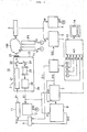
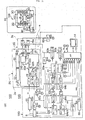
- the control/analyzing part 19D provided in the observation room 90 near the forest observation tower 91 comprises the LD controller 11 controlling the oscillated laser beam from a semi-conductor laser (LD) 28, first wavelength modulation waveform generator (No. 1-FG) 61/ second wavelength modulation waveform generator (No. 2-FG) 62 both modulating the laser beam, direct current detectors (LPF) 65a to 65c functioning as mentioned below, first phase sensitive detectors (No. 1-PSD-G, Z, R, FB) 63 (63a to 63d) / second phase sensitive detectors (No.
- LD controller 11 controlling the oscillated laser beam from a semi-conductor laser (LD) 28, first wavelength modulation waveform generator (No. 1-FG) 61/ second wavelength modulation waveform generator (No. 2-FG) 62 both modulating the laser beam, direct current detectors (LPF) 65a to 65c functioning as mentioned below, first phase sensitive detectors (No. 1-PSD-G, Z, R, FB) 63 (63a to 63
- 2-PSD-G, Z, R, FB) 64 64 (64a to 64d) functioning as mentioned below, the A/D converter 13 taking all of the respective signals, the computer 14 (personal computer) analyzing A/D converted signals so that the CO 2 concentration and CO 2 flux in the air are analyzed and recorded and the adder 9 adding together the modulation signals from the first waveform generator (No. 1-FG) 61 and second waveform generator (No. 2-FG) 62 and the wavelength fixing signal from the second phase sensitive detector (No. 2-PSD-FB) 64d and putting out a signal as an external control signal into the LD control unit 11.
- the A/D converter 13 taking all of the respective signals
- the computer 14 personal computer
- the adder 9 adding together the modulation signals from the first waveform generator (No. 1-FG) 61 and second waveform generator (No. 2-FG) 62 and the wavelength fixing signal from the second phase sensitive detector (No. 2-PSD-FB) 64d and putting out a signal as an external control signal into the LD control unit 11.
- the direct current detectors (LPF) 65a to 65c function to detect the direct current component out of the received light signals from respective light receivers (PD-G, PD-R, PD-Z) 29a to 29c and put out received light strength signals S23, S22, S21.
- the first phase sensitive detectors (No. 1-PSD-G, Z, R, FB) 63 (63a to 63d) function, based on the reference signals from the first wavelength modulation waveform generator 61, to detect only such signals as synchronized with a double wave frequency component of the modulation frequency from the respective received light signals and put them out.
- the second phase sensitive detectors No.
- 2-PSD-G, Z, R, FB) 64 64a to 64d function, based on the reference signals from the second wavelength modulation waveform generator (No. 2-FG) 62, to detect only such signals as synchronized with the double wave frequency component of the modulation frequency from the output signals from the first phase sensitive detectors 63.
- FG wavelength sweep waveform generator
- SW change-over switch
- the measuring part 2D comprises therein the ultrasonic current meter 51, a semi-conductor type pressure sensor 53 and a temperature sensor 52. These current meter 51 and sensors 52, 53 are provided near a blow-off port of the sampling pipe 91 and put out a measured flow velocity signal S19, measured temperature signal S2 and measured pressure signal S3, respectively, into the computer 14 as the analyzing part via the A/D converter 13.
- the single semi-conductor laser (LD) 28 can adjust the laser oscillation wavelength to one of the absorption wavelengths of CO 2 .
- the optical system comprises a first half mirror 22a, second half mirror 22b and reflecting mirror 24.
- the first half mirror 22a transmits a portion of the laser beam oscillated from the light source 28 to be distributed to the optical window 23 so that this laser beam is radiated toward the light receiver (PD-G) 29a for measuring purpose.
- the first half mirror 22a reflects a portion of the oscillated laser beam to be distributed to the second half mirror 22b.
- the second half mirror 22b reflects a portion of the distributed laser beam to be further distributed to the reference cell 25 and, at the same time, transmits a portion of the distributed laser beam to be distributed to the zero reference part (PD-Z) 29c via the reflecting mirror 24.
- the laser beam that has been transmitted through the reference cell 25 enters the light receiver (PD-R) 29b for reference purpose so that a received light signal is put out into a direct current detector (LPF) 65b of the control/analyzing part 19D.
- the direct current detector (LPF) 65b removes an alternating current component as a modulation signal from the received light signal and puts out a signal S22 thereof into the computer 14.
- the direct current detector (LPF) 65c removes an alternating current component as a modulation signal from the received light signal and puts out the signal S21 thereof into the computer 14.
- the light receiver (PD-G) 29a for measuring purpose puts out the received light signal into a direct current detector (LPF) 65a and first phase sensitive detector (No. 1-PSD-G) 63a, respectively, of the control/analyzing part 19D.
- LPF direct current detector
- the direct current detector (LPF) 65a removes an alternating current component as a modulation signal from the received light signal and puts out the signal S23 thereof into the computer 14.
- the first phase sensitive detector No.
- 1-PSD-G 63a detects an even number order harmonic component of the wavelength modulation signal added to the laser beam out of the signal put out from the light receiver 29a for measuring purpose and puts out a signal in proportion to the concentration of the enclosed gas in the reference cell into a second phase sensitive detector (No. 2-PSD-G) 64a. Also, based on the wavelength modulation reference signal from the second wavelength modulation waveform generator (No. 2-FG) 62, a second phase sensitive detector (No. 2-PSD-G) 64a detects an odd number order harmonic component of the wavelength modulation signal added to the laser beam out of the signal put out from the light receiver 29a and puts out a signal S24 in proportion to the concentration of the enclosed gas in the reference cell into the computer 14.
- the wavelength sweep waveform generator (FG) 66 is constructed such that a ramp wave of frequency of 0.5 Hz or 0.01 Hz, for example, is applied to an injection current of the semi-conductor laser element. It is to be noted that in case where the changes of the gas concentration are to be measured for a long time, the sweep of the laser oscillation wavelength by the wavelength sweep waveform generator 66 is stopped and the laser oscillation wavelength is locked to a predetermined wavelength. The wavelength sweep waveform generator 66 puts out a wavelength sweep signal S28 into the computer 14.
- the two wavelength modulation waveform generators 61, 62 are constructed such that sine waves of frequencies different from each other are doubly applied to the injection current of the semi-conductor laser element 28.
- the adder 9 superposes a sweep signal S29 from the wavelength sweep waveform generator 66, modulation signals S25, S26 of the different frequencies f, w from the two wavelength modulation waveform generators 61, 62 and a third order differential demodulation signal S27 of the frequency 2f + w from the phase sensitive detectors 63a to 63d, 64a to 64d of two steps and the result thereof is applied to the injection current of the semi-conductor laser element.
- the laser oscillation wavelength is doubly modulated by the two different frequencies f, w.
- the received light signal of the laser beam includes both the modulation frequencies f, w and harmonic components thereof.
- the signals are demodulated in the frequency of two times, that is, 20 KHz (2f), by the first phase sensitive detectors 63a to 63d and are then demodulated in the frequency of two times, that is, 1 KHz (2w), by the second phase sensitive detectors 64a to 64d.
- a fourth order differential signal (2f + 2w) in which these demodulated signals are superposed is sent to the computer 14.
- the signals demodulated in the frequency of two times, that is, 20 KHz (2f), by the first phase sensitive detectors 63a to 63d are demodulated in the frequency w by the second phase sensitive detectors 64a to 64d.
- a third order differential signal (2f + w) in which these demodulated signals are superposed is sent to the adder 9 via the change-over switch 67. Based on this signal, the laser oscillation wavelength is applied with a feedback control to the absorption central wavelength of the measuring object gas.
- the wind velocity on the tower 91 is measured by the ultrasonic current meter 51 and a wind velocity signal (S) thereof is put out into the control/analyzing part 19D of the observation room 90.
- the pressure of the measuring region 100 is measured by a semi-conductor type pressure sensor 53 and a measured pressure signal S3 thereof is put out into the observation room 90.
- the temperature of the measuring region 100 is measured by a thermocouple (temperature sensor) 52 and a measured temperature signal S2 thereof is put out into the computer 14.
- a measurement by a laser may also be employed making use of the characteristic of the absorption spectrum of the measuring object gas.
- a ramp wave of 0.5 Hz or 0.01 Hz, for example, is applied to the injection current by the wavelength sweep waveform generator (FG) 66 so that sweeping of the laser wavelength is slowly carried out. If concentration changes for a long time are to be measured, the laser wavelength is locked.
- comparison example 1 for the purpose of comparison, conventional measurements are also carried out as a comparison example 1 such that sampling of the air is done from substantially the same position as the measuring region of the present disclosure and the air is pretreated by the pretreatment device 94 and measured by the prior art CO 2 meter 93 so that the measurement result is analyzed by the eddy correlation method together with the measurement result of the ultrasonic current meter 51 and, at the same time, the CO 2 flux is measured.
- Fig. 6 is a characteristic diagram showing the result of the Measurement 1, wherein the horizontal axis shows the measuring time and the vertical axis shows the measured CO 2 flux (mg/m 2 ⁇ S).
- a solid line A1 shows the result of the Measurement 1 according to the device of the present disclosure
- a broken line B1 shows the result of the comparison example 1 measured by a conventional device using the sampling method.
- Measurement 2 an example of measuring the regional CO 2 flux between two forest observation towers using a combination of the TDLAS regional gas concentration measuring device and the scintillation method according to the present disclosure as still another example will be described with reference to Figs. 7(a) and (b) . It is to be noted that as to the parts and components of the present example substantially the same as those of the above described examples, descriptions thereof will be omitted.
- a wavelength TDLAS type gas concentration measuring device and a scintillation method type momentum flux measuring device are provided on the forest observation towers and the result of measurements by these two devices are analyzed based on the MOS law, so that the regional CO 2 flux between the forest observation towers is measured.
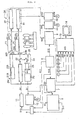
- Figs. 7(a) and (b) show a device system used for the present Measurement 2.
- Construction of a wavelength TDLAS type gas concentration measuring device system 2E including 19E is substantially the same as the device system 2D including 19D used for the Measurement 1 shown in Figs. 5(a) and (b) .
- a control/analyzing part 19E provided in the observation room 90 is substantially the same as the control/analyzing part 19D of the Measurement 1 shown in Figs. 5(a) and (b) .
- reference letters FG designate a waveform generator
- reference letters PSD a phase sensitive detector
- reference letter G a measuring part
- reference letter R a reference part
- reference letter Z a background CO 2 measurement
- reference letters FB a wavelength fixing and reference letter S a scintillation measuring part.
- a light source part 2E provided on a first forest observation tower 91 comprises a TDLAS optical system unit 20 having substantially the same construction as the unit 20 of the above Measurement 1 as well as comprises the scintillation measuring unit 70 shown in Figs. 15C and D .
- a reference part received light signal S22 and zero part received light signal S21 as well as a strength modulation reference signal S24 of the scintillation measuring unit 70 are put out into the control/analyzing part 19E of the observation room 90 and, at the same time, an LD control signal S21 is put out from the control/analyzing part 19E of the observation room 90 into the TDLAS optical system unit 20.
- two scintillation measuring laser oscillators 71, 72 are mounted so that an oscillated laser is radiated to the measuring region 100 through optical windows 73a, 73b, respectively, to be received by a light receiving part 3E provided on a second forest observation tower 92.
- a semi-conductor type pressure sensor 53 and a thermocouple (temperature sensor) 52 are provided on the first forest observation tower 91 and measurement values thereof are representatively used as the pressure and temperature of the measuring region 100.
- the average pressure and average temperature of the measuring region 100 may also be measured by a laser.
- the light receiving part 3E provided on the second forest observation tower 92 comprises a light receiver (PD-G) 35 receiving a laser beam radiated from the TDLAS optical system unit 20 of the light source part 2E provided on the first forest observation tower 91 and transmitted through the atmospheric air and two light receivers (PD-S 1, PD-S2) 33, 34 receiving the laser beams radiated from the scintillation measuring unit 70.
- Respective received light signals S23, S 191, S 192 (G, S1, S2) thereof are put out into the control/analyzing part 19E of the observation room 90 for analysis.
- a signal transmission [shown by * mark in Fig. 7(a) ] from the light source part 2E and light receiving part 3E on the towers 91, 92 to the observation room 90 is carried out by electric wiring cables using usual metal wires.
- the present disclosure is not limited thereto but, in order to correspond to cases where the measuring length is further elongated, a signal transmission method by an optical fiber system or wireless system in which communication facilities are easily installed may also be employed.
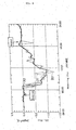
- Fig. 8 is a characteristic diagram showing the result of the Measurement 2, wherein the horizontal axis shows the measuring time and the vertical axis shows the measured CO 2 flux (mg/m 2 ⁇ S).
- a solid line A2 shows the result of the Measurement 2 according to the device of the present disclosure
- broken line B2 shows the result of a comparison example 1 in which the concentration measurement by a prior art CO 2 meter and the flux measurement by the ultrasonic current meter on the first observation tower 91 are combined
- a two-dot chain line C2 shows the result of a comparison example 2 in which the concentration measurement by a prior art CO 2 meter and the flux measurement by an ultrasonic current meter on the second observation tower 92 are combined.
- the result of the present Measurement 2 (the characteristic line A2) forms a change curve that is smoother than the results of the comparison examples 1, 2 (the characteristic lines B2, C2). This is because of the feature of the present disclosure in that there is no obstruction (or no external disturbance) at all between the light source part and the light receiving part.
- the measurement results of the comparison examples using the prior art there are generated many notches in the change curves. This is because of the prior art problem in that there are provided many measuring devices, creating interferences with each other, in the measuring region and the existence itself of such measuring devices becomes the cause of the external disturbances.
- the measurement result of the regional CO 2 flux according to the present disclosure (the characteristic line A2) directly based on the measuring results of the comparison examples using the prior art (the characteristic lines B2, C2)
- the measurement result of the present disclosure approximately accords with the result of the measurements carried out on each of the towers using the prior art.
- the present disclosure is appropriate for real time measurements of the regional CO 2 flux.
- Measurement 3 an example of measuring the regional CO 2 flux between two forest observation towers using a semi-conductor laser type gas flux measuring device according to the present disclosure as still another example will be described with reference to Figs. 9(a) and (b) . It is to be noted that as to the parts and components of the present example substantially the same as those of the above described examples, descriptions thereof will be omitted.
- a semi-conductor laser type gas flux measuring device system 2F including 3F as a single unit of the wavelength TDLAS type gas concentration measuring device added with a scintillation method function is provided on the forest observation towers 91, 92 and the result of measurements thereof are analyzed based on the MOS law, so that the regional CO 2 flux between the forest observation towers 91, 92 is measured.
- the measuring length L2 is set to 81 m that equals the distance between the towers 91, 92.
- Figs. 9(a) and (b) show a device system used for the present Measurement 3. While the construction of a wavelength TDLAS type gas concentration measuring device system 2F including 3F is substantially the same as the representative device construction shown in Fig. 2 , like in the Measurements 1, 2, in order to enhance the measuring sensitivity and measuring stability, a double wavelength modulation mechanism and zero point measuring mechanism are additionally provided. Also, a control/analyzing part 19F provided in the observation room 90 is substantially the same as the control/analyzing part 19D of the Measurement 2 shown in Figs. 7(a) and (b) .
- a light source part 2F provided on the first forest observation tower 91 is constructed such that the basic construction of the TDLAS optical system unit 20 of the Measurements 1, 2 is provided with a laser oscillator (LD2) 28b separately from a light source (LD1) 28a for gas concentration measuring purpose.
- LD2 laser oscillator
- LD1 light source
- the semi-conductor type pressure sensor 53 and the thermocouple (temperature sensor) 52 are provided on the first forest observation tower 91 and measurement values thereof are representatively used as the pressure and temperature of the measuring region 100. But using characteristics of the absorption spectrum of the measuring object gas, the average pressure and average temperature of the measuring region 100 may also be measured by a laser.
- the light receiving part 3F provided on the second forest observation tower 92 comprises light receivers (PD-G, PD-S) 29a, 29b receiving a laser beam radiated from the optical unit 20 and transmitted through the air between the two towers 91, 92. Respective received light signals S20, S23 thereof are put out into the control/analyzing part 19F of the observation room 90 for analysis.
- a signal transmission [shown by * mark in Fig. 9(a) ] thereof is carried out by usual electric wiring cables, in order to correspond to cases where the measuring length is further elongated, a signal transmission method by an optical fiber system or wireless system in which communication facilities are easily installed may also be employed.
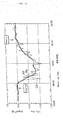
- Fig. 10 is a characteristic diagram showing the result of the Measurement 3, wherein the horizontal axis shows the measuring time and the vertical axis shows the measured CO 2 flux (mg/m 2 ⁇ S).
- a solid line A3 shows the result of the Measurement 3 according to the device of the present disclosure
- a broken line B3 shows the result of a comparison example 1 in which the concentration measurement by a prior art CO 2 meter and the flux measurement by an ultrasonic current meter on the first observation tower 91 are combined
- a two-dot chain line C3 shows the result of a comparison example 2 in which the concentration measurement by a prior art CO 2 meter and the flux measurement by an ultrasonic current meter on the second observation tower 92 are combined.
- the result of the present Measurement 3 (the characteristic line A3) forms a change curve that is smoother than the results of the comparison examples 1, 2 (the characteristic lines B3, C3).
- the feature of the present disclosure in that there is no obstruction (or no external disturbance) at all between the light source part and the light receiving part.
- there are generated many notches in the change curves in the measurement results of the comparison examples using the prior art, there are generated many notches in the change curves. This is because of the prior art problem in that there are provided many measuring devices, creating interferences with each other, in the measuring region and the existence itself of such measurement devices becomes the cause of the external disturbances.
- the measurement result of the regional CO 2 flux according to the present disclosure (the characteristic line A3) directly based on the measurement results of the comparison examples using the prior art (the characteristic lines B3, C3)
- the measurement result of the present disclosure approximately accords with the result of the measurements carried out on each of the towers using the prior art.
- the present disclosure is appropriate for real time measurements of the regional CO 2 flux.
- Measurement 4 an example of measuring the regional CO 2 flux between two forest observation towers using a semi-conductor laser type gas flux measuring device according to the present disclosure as still another example will be described with reference to Figs. 11(a) and (b) . It is to be noted that as to the parts and components of the present example substantially the same as those of the above described examples, descriptions thereof will be omitted.
- a semi-conductor laser type gas flux measuring device system 2G including 3G as a single unit of the wavelength TDLAS type gas concentration measuring device added with a scintillation method function is provided on the forest observation towers 91, 92 and the result of measurements thereof are analyzed based on the MOS law, so that the regional CO 2 flux between the forest observation towers 91, 92 is measured.
- the measuring length L2 is set to 81m that equals the distance between the towers 91, 92.
- Figs. 11(a) and (b) show a device system used for the present Measurement 4. While the construction of the wavelength TDLAS type gas concentration measuring device system is substantially the same as the representative device construction shown in Fig. 3 , like in the Measurements 1, 2, in order to enhance the measuring sensitivity and measuring stability, a double wavelength modulation mechanism and zero point measuring mechanism are additionally provided.
- a light source part 2G provided on the first forest observation tower 91 is constructed such that the basic construction of the TDLAS optical system unit of the Measurements 1, 2 is provided with a polarization plane rotating device 27G distributing a laser beam for measuring purpose to two portions and, while rotating a laser polarization plane of one of the two portions by an angle of 90°, oscillating the laser beam toward the measuring region.
- the reference part received light signal S22 and zero part received light signal S21 are put out into a control/analyzing part 19G of the observation room 90 and, at the same time, the LD control signal S1 is put out from the control/analyzing part 19G of the observation room 90 into the TDLAS optical system unit 20.
- the polarization plane rotating device 27G comprises a Faraday rotator, so that the polarization plane of the laser beam oscillated from the semi-conductor laser beam source (LD) 28 is rotated and the laser polarization plane is converted between the vertical polarization and the horizontal polarization.
- LD semi-conductor laser beam source
- the semi-conductor type pressure sensor 53 and the thermocouple (temperature sensor) 52 are provided on the first forest observation tower 91 and measurement values 20 thereof are representatively used as the pressure and temperature of the measuring region 100. But using characteristics of the absorption spectrum of the measuring object gas, the average pressure and average temperature of the measuring region 100 may also be measured by a laser.
- the light receiving part 3G provided on the second forest observation tower 92 comprises the two light receivers (PD-G, PD-S) 29a, 29b receiving the two laser beams radiated from the optical unit 20 and transmitted through the air between the two towers 91, 92.
- the respective received light signals S20, S23 thereof are put out into the control/analyzing part 19G of the observation room 90 for analysis.
- a signal transmission [shown by * mark in Fig. 11(a) ] thereof is carried out by usual electric wiring cables, in order to correspond to cases where the measuring length is further elongated, a signal transmission method by an optical fiber system or wireless system in which communication facilities are easily installed may also be employed.
- the control/analyzing part 19G provided in the observation room 90 is substantially the same as that of the Measurement 2 shown in Figs. 7(a) and (b) .
- Fig. 12 is a characteristic diagram showing the result of the Measurement 4, wherein the horizontal axis shows the measuring time and the vertical axis shows the measured CO 2 flux (mg/m 2 ⁇ S).
- a solid line A4 shows the result of the Measurement 4 according to the device of the present disclosure
- a broken line B4 shows the result of a comparison example 1 in which the concentration measurement by a prior art CO 2 meter and the flux measurement by an ultrasonic current meter on the first observation tower 91 are combined
- a two-dot chain line C4 shows the result of a comparison example 2 in which the concentration measurement by a prior art CO 2 meter and the flux measurement by an ultrasonic current meter on the second observation tower 92 are combined.
- the measurement result of the regional CO 2 flux While it is difficult to verify the measurement result of the regional CO 2 flux according to the present disclosure directly based on the measuring results using the prior art, the measurement result of the present disclosure approximately accords with the result of the measurements carried out on each of the towers using the prior art. Thus, it is verified that the present disclosure is appropriate for real time measurements of the regional CO 2 flux.
- Measurement 5 an example of measuring the regional CO 2 flux between two forest observation towers using a semi-conductor laser type gas flux measuring device according to the present disclosure as still another example will be described with reference to Figs. 13(a) and (b) . It is to be noted that as to the parts and components of the present example substantially the same as those of the above described examples, descriptions thereof will be omitted.
- a semi-conductor laser type gas flux measuring device system 2H including 3H as a single unit of the wavelength TDLAS type gas concentration measuring device added with a scintillation method function is provided on the forest observation towers 91, 92 and the result of measurements thereof are analyzed based on the MOS law, so that the regional CO 2 flux between the forest observation towers 91, 92 is measured.
- the measuring length L2 is set to 81m that equals the distance between the towers 91, 92.
- Figs. 13(a) and (b) show a device system used for the present Measurement 5.
- the polarization plane modulation frequency is sufficiently lower as compared with the wavelength modulation frequency
- the construction of the wavelength TDLAS type gas concentration measuring device system is substantially the same as the representative device construction shown in Fig. 4 , like in the Measurements 1, 2, in order to enhance the measuring sensitivity and measuring stability, a double wavelength modulation mechanism and zero point measuring mechanism are additionally provided.
- a light source part 2H provided on the first forest observation tower 91 is constructed such that the basic construction of the TDLAS optical system unit of the Measurements 1, 2 is provided with a polarization plane modulator 59 providing a polarization plane modulating function and the optical unit 20 added with a modulation controller 58 therefor.
- the reference part received light signal S22 and zero part received light signal S21 as well as a polarization plane modulation reference signal S37 are put out into a control/analyzing part 19H of the observation room 90 and, at the same time, the LD control signal S1 is put out from the control/analyzing part 19H of the observation room 90 into the optical system unit 20.
- the semi-conductor type pressure sensor 53 and the thermocouple (temperature sensor) 52 are provided on the first forest observation tower 91 and measurement values thereof are representatively used as the pressure and temperature of the measuring region 100. But using characteristics of the absorption spectrum of the measuring object gas, the average pressure and average temperature of the measuring region 100 may also be measured by a laser.
- the control/ analyzing part 19H provided in the observation room 90 is additionally provided with a third phase sensitive detector (No. 3-PSD-G) 64e detecting, based on the polarization modulation reference signal S37, a signal component synchronized with the modulation out of the signal put out from the second phase sensitive detector (No. 2- PSD-G) 64a, a phase sensitive detector (No.
- 1-PD-S 64f taking out a received light strength signal of the vertically polarized laser or horizontally polarized laser out of the PD-G received light signal and a phase shifter 68 putting out a signal S36 for shifting the phase of the polarization plane modulation reference signal S37 and, instead thereof, the direct current component detector for the received light strength signal is omitted.
- the light receiving part 3H provided on the second forest observation tower 92 comprises a light receiver (PD-G) 29 receiving a laser beam radiated from the optical unit 20 and transmitted through the air between the two towers 91, 92.
- a received light signal S22 thereof is put out into the control/ analyzing part 19H of the observation room 90 for analysis.
- a signal transmission [shown by * mark in Fig. 13(a) ] thereof is carried out by usual electric wiring cables, in order to correspond to cases where the measuring length is further elongated, a signal transmission method by an optical fiber system or wireless system in which communication facilities are easily installed may also be employed.
- Fig. 14 is a characteristic diagram showing the result of the Measurement 5, wherein the horizontal axis shows the measuring time and the vertical axis shows the measured CO 2 flux (mg/m 2 ⁇ S).
- a solid line A5 shows the result of the Measurement 5 according to the device of the present disclosure
- a broken line B5 shows the result of a comparison example 1 in which the concentration measurement by a prior art CO 2 meter and the flux measurement by an ultrasonic current meter on the first observation tower 91 are combined
- a two-dot chain line C5 shows the result of a comparison example 2 in which the concentration measurement by a prior art CO 2 meter and the flux measurement by an ultrasonic current meter on the second observation tower 92 are combined.
- the measurement result of the regional CO 2 flux While it is difficult to verify the measurement result of the regional CO 2 flux according to the present disclosure directly based on the measuring results of the comparison examples using the prior art, the measurement result of the present disclosure approximately accords with the result of the measurements carried out on each of the towers using the prior arts. Thus, it is verified that the present disclosure is appropriate for real time measurements of the regional CO 2 flux.
- the gas flux measuring device is appropriate to be used for monitoring an existing quantity of regional greenhouse gases (GHG), that is, for example, for assessing a CO 2 absorption quantity by a forest, carrying out an environment investigation, such as an investigation of generation quantity of GHG coming out of the ground, or for detecting a gas leakage from CO 2 underground disposal plants, gas storage facilities, pipelines, etc.
- GOG regional greenhouse gases
Landscapes
- Physics & Mathematics (AREA)
- Spectroscopy & Molecular Physics (AREA)
- General Physics & Mathematics (AREA)
- Health & Medical Sciences (AREA)
- Life Sciences & Earth Sciences (AREA)
- Chemical & Material Sciences (AREA)
- Analytical Chemistry (AREA)
- Biochemistry (AREA)
- General Health & Medical Sciences (AREA)
- Immunology (AREA)
- Pathology (AREA)
- Investigating Or Analysing Materials By Optical Means (AREA)
Abstract
Claims (6)
- Dispositif de mesure de flux de gaz, dans lequel :ledit dispositif de mesure de flux de gaz comprend :une source de lumière (21) unique pour faire osciller un faisceau laser à une longueur d'onde d'absorption naturelle pour un gaz objet de mesure vers une région de mesure,un contrôleur de sortie de laser (11) pour commander une action de sortie de ladite source de lumière (21),un contrôleur de modulation de longueur d'onde (6) pour sortir un signal de modulation pour ajouter une modulation à une longueur d'onde d'oscillation du faisceau laser mis en oscillation provenant de ladite source de lumière (21) ainsi que pour sortir un signal de référence synchronisé avec la modulation,un premier récepteur de lumière (31) pour recevoir le faisceau laser transmis à travers la région de mesure et pour sortir un signal correspondant à une intensité de lumière reçue de celui-ci,un premier démodulateur de modulation de longueur d'onde (5) pour détecter, sur la base du signal de référence provenant dudit contrôleur de modulation de longueur d'onde (6), une composante harmonique d'ordre pair du signal de modulation de longueur d'onde ajouté au faisceau laser dans le signal sorti dudit premier récepteur de lumière (31) et pour sortir un signal proportionnel à une concentration du gaz objet de mesure dans la région de mesure,un système optique (10B) pour distribuer le faisceau laser mis en oscillation provenant de ladite source de lumière vers deux parties ou plus,une cellule de référence (25) entourant ledit gaz objet de mesure dont la concentration est connue et agencée à une position telle que le faisceau laser distribué par ledit système optique de manière à ne pas être dirigé vers la région de mesure soit transmis à travers le gaz confiné,un deuxième récepteur de lumière (26) pour recevoir le faisceau laser transmis à travers le gaz confiné dans ladite cellule de référence (25) et pour sortir un signal correspondant à une intensité de lumière reçue de celui-ci,un deuxième détecteur de composante continue (12) pour retirer une composante alternative en tant que signal de modulation du signal sorti dudit deuxième récepteur de lumière et pour sortir une composante continue de l'intensité de lumière reçue,un deuxième démodulateur de modulation de longueur d'onde (6) pour détecter, sur la base du signal de référence provenant dudit contrôleur de modulation de longueur d'onde (6), une composante harmonique d'ordre pair du signal de modulation de longueur d'onde ajouté au faisceau laser dans le signal sorti dudit deuxième récepteur de lumière et pour sortir un signal proportionnel à la concentration du gaz confiné dans ladite cellule de référence,un troisième démodulateur de modulation de longueur d'onde (7) pour détecter, sur la base du signal de référence provenant dudit contrôleur de modulation de longueur d'onde, une composante harmonique d'ordre impair du signal de modulation de longueur d'onde ajouté au faisceau laser dans le signal sorti dudit deuxième récepteur de lumière et pour sortir un signal d'établissement de longueur d'onde de laser en tant que signal standard pour établir la longueur d'onde de faisceau laser à la longueur d'onde d'absorption du gaz objet de mesure,un analyseur (13, 14) pour calculer, sur la base des signaux sortis desdits premier démodulateur de modulation de longueur d'onde (5), deuxième détecteur de composante continue (12) et deuxième démodulateur de modulation de longueur d'onde (6), la concentration de gaz et une concentration de particules solides dans la région de mesure et pour sortir un résultat de calcul de celles-ci,un additionneur (9) additionnant le signal de modulation provenant dudit contrôleur de modulation de longueur d'onde et le signal d'établissement de longueur d'onde de laser provenant dudit troisième démodulateur de modulation de longueur d'onde et sortant un signal d'addition de ceux-ci en tant que signal de commande externe dans ledit contrôleur de sortie de laser (11),des moyens de mesure de température (T1) pour mesurer une température dans la région de mesure et pour sortir un signal correspondant à une valeur mesurée de celle-ci dans ledit analyseur, etdes moyens de mesure de pression (P1) pour mesurer une pression dans la région de mesure et pour sortir un signal correspondant à une valeur mesurée de celle-ci dans ledit analyseur ;ledit dispositif de mesure de flux de gaz comprend en outre :un dispositif de rotation de plan de polarisation (27) comportant un rotateur de Faraday commandé extérieurement et pour faire tourner un plan de polarisation du faisceau laser mis en oscillation provenant de ladite source de lumière (21) unique,un contrôleur de modulation de plan de polarisation (15) pour commander un angle de rotation dudit rotateur de Faraday de manière à commuter le plan de polarisation de laser entre une polarisation verticale et une polarisation horizontale avec une période prédéterminée,un premier démodulateur de plan de polarisation (17a) pour détecter, sur la base d'un signal de référence de modulation d'intensité provenant dudit contrôleur de modulation de plan de polarisation, un signal synchronisé avec une modulation de plan de polarisation dans le signal sorti dudit premier récepteur de lumière et pour sortir un signal proportionnel à une intensité de lumière reçue d'un faisceau laser polarisé verticalement transmis à travers la région de mesure en tant que signal de quantité d'absorption de laser de région de mesure dans ledit analyseur,un deuxième démodulateur de plan de polarisation (17b) pour détecter, sur la base du signal de référence de modulation d'intensité provenant dudit contrôleur de modulation de plan de polarisation, un signal synchronisé avec la modulation de plan de polarisation dans le signal sorti dudit premier récepteur de lumière et pour sortir un signal proportionnel à une intensité de lumière reçue d'un faisceau laser polarisé horizontalement transmis à travers la région de mesure en tant que signal de quantité d'absorption de laser de région de mesure dans ledit analyseur, etun troisième démodulateur de plan de polarisation (18) pour détecter, sur la base du signal de référence de modulation d'intensité provenant dudit contrôleur de modulation de plan de polarisation, un signal synchronisé avec la modulation de plan de polarisation dans le signal sorti dudit premier récepteur de lumière et pour sortir un signal proportionnel à une intensité de lumière reçue du faisceau laser transmis à travers la région de mesure en tant que signal de mesure de concentration dans ledit analyseur ; etledit analyseur est configuré pour obtenir, sur la base des signaux reçus desdits premier, deuxième et troisième démodulateurs de plan de polarisation, des changements dans le temps d'un facteur de transmission de laser, pour obtenir, sur la base de ces changements dans le temps du facteur de transmission de laser, des changements dans le temps d'une densité de gaz, pour effectuer une analyse sur la base d'une loi de similarité de Monin-Obukhov afin de saisir un état de turbulence du gaz objet de mesure en utilisant les changements dans le temps de la densité de gaz et pour obtenir, par un calcul en utilisant un résultat d'analyse de celui-ci, un flux de quantité de mouvement dans la région de mesure, un flux de concentration du gaz objet de mesure et la concentration du gaz objet de mesure.
- Dispositif de mesure de flux de gaz selon la revendication 1, dans lequel ledit troisième démodulateur de plan de polarisation (18) est prévu en aval dudit premier démodulateur de modulation de longueur d'onde (17a) et une fréquence de modulation de plan de polarisation de celui-ci est fixée de manière à être inférieure à une fréquence de modulation de longueur d'onde de celui-ci.
- Dispositif de mesure de flux de gaz selon la revendication 1, dans lequel ledit troisième démodulateur de plan de polarisation (18) est prévu en amont dudit premier démodulateur de modulation de longueur d'onde (17a) et une fréquence de modulation de plan de polarisation de celui-ci est fixée de manière à être supérieure à une fréquence de modulation de longueur d'onde de celui-ci.
- Dispositif de mesure de flux de gaz selon la revendication 1, caractérisé en ce qu'il comprend en outre un convertisseur de phase de signal prévu en amont desdits premier et deuxième démodulateurs de plan de polarisation pour convertir une phase du signal de référence de modulation de plan de polarisation provenant dudit contrôleur de modulation de plan de polarisation.
- Dispositif de mesure de flux de gaz selon la revendication 4, dans lequel ladite source de lumière (21) et le premier récepteur de lumière (31) sont montés dans le même conteneur.
- Dispositif de mesure de flux de gaz selon la revendication 5, dans lequel lesdits moyens de mesure de température (T1) et moyens de mesure de pression (P1) sont également montés dans ledit même conteneur.
Applications Claiming Priority (2)
| Application Number | Priority Date | Filing Date | Title |
|---|---|---|---|
| JP2003338466A JP4317728B2 (ja) | 2003-09-29 | 2003-09-29 | ガス濃度フラックス計測装置 |
| PCT/JP2004/014159 WO2005031275A2 (fr) | 2003-09-29 | 2004-09-28 | Dispositif de mesure de flux de concentration de gaz |
Publications (3)
| Publication Number | Publication Date |
|---|---|
| EP1669736A2 EP1669736A2 (fr) | 2006-06-14 |
| EP1669736A4 EP1669736A4 (fr) | 2009-12-30 |
| EP1669736B1 true EP1669736B1 (fr) | 2011-03-23 |
Family
ID=34386157
Family Applications (1)
| Application Number | Title | Priority Date | Filing Date |
|---|---|---|---|
| EP20040788226 Expired - Fee Related EP1669736B1 (fr) | 2003-09-29 | 2004-09-28 | Dispositif de mesure de flux de concentration de gaz |
Country Status (11)
| Country | Link |
|---|---|
| US (1) | US7365352B2 (fr) |
| EP (1) | EP1669736B1 (fr) |
| JP (1) | JP4317728B2 (fr) |
| CN (1) | CN1860360B (fr) |
| AU (2) | AU2004276642B2 (fr) |
| CA (2) | CA2689693A1 (fr) |
| DE (1) | DE602004031962D1 (fr) |
| DK (1) | DK1669736T3 (fr) |
| NO (1) | NO20061901L (fr) |
| RU (1) | RU2308023C1 (fr) |
| WO (1) | WO2005031275A2 (fr) |
Families Citing this family (47)
| Publication number | Priority date | Publication date | Assignee | Title |
|---|---|---|---|---|
| JP4227991B2 (ja) * | 2005-12-28 | 2009-02-18 | トヨタ自動車株式会社 | 排ガス分析装置および排ガス分析方法 |
| JP4594277B2 (ja) | 2006-05-31 | 2010-12-08 | トヨタ自動車株式会社 | 排ガス分析装置におけるセンサユニット |
| JP4732277B2 (ja) * | 2006-08-23 | 2011-07-27 | トヨタ自動車株式会社 | ガス分析装置及びガス分析方法 |
| JP4823020B2 (ja) * | 2006-11-01 | 2011-11-24 | 三菱重工業株式会社 | ガス濃度モニタリングシステム、固定局及び移動局、並びにガス濃度計測方法 |
| US7969576B1 (en) * | 2007-03-23 | 2011-06-28 | The Regents Of The University Of California | Optical sensing based on wavelength modulation spectroscopy |
| JP4713530B2 (ja) * | 2007-03-23 | 2011-06-29 | 日本電信電話株式会社 | 浮遊粒子状物質測定装置 |
| US7747417B2 (en) * | 2007-08-06 | 2010-06-29 | Arizona Public Service Company | Method and system for transformer dissolved gas harmonic regression analysis |
| US8253942B2 (en) * | 2007-09-27 | 2012-08-28 | Scott Technologies, Inc. | Optical gas detector |
| JP5371268B2 (ja) * | 2008-03-14 | 2013-12-18 | 三菱重工業株式会社 | ガス濃度計測方法および装置 |
| JP5314301B2 (ja) * | 2008-03-14 | 2013-10-16 | 三菱重工業株式会社 | ガス濃度計測方法および装置 |
| JP2010032454A (ja) * | 2008-07-31 | 2010-02-12 | Fuji Electric Systems Co Ltd | ガス分析装置及びガス分析方法 |
| JP5357506B2 (ja) * | 2008-10-29 | 2013-12-04 | 三菱重工業株式会社 | 濃度測定方法および装置 |
| KR101648731B1 (ko) * | 2009-02-02 | 2016-08-17 | 플래너테리 이미션즈 매니지먼트 | 온실가스 유출입량을 모니터하기 위한 복합 시스템 |
| AU2010259934B2 (en) * | 2009-06-12 | 2014-10-30 | Spectrasensors, Inc. | Optical absorbance measurements with self-calibration and extended dynamic range |
| US9229131B2 (en) * | 2009-09-02 | 2016-01-05 | University Of Kwazulu-Natal | Method and system for estimating evaporation representative of an area |
| AU2009292601B1 (en) * | 2009-09-03 | 2010-06-17 | Li-Cor, Inc. | Method and apparatus for determining gas flux |
| US7953558B2 (en) * | 2009-09-03 | 2011-05-31 | Li-Cor, Inc. | Method and apparatus for determining gas flux |
| US8269971B1 (en) * | 2009-11-12 | 2012-09-18 | Exelis, Inc. | System and method for simultaneous detection of a gas using a mode-locked based transmitter |
| US8184297B2 (en) * | 2009-12-17 | 2012-05-22 | General Electric Company | Gas mixture measurement system and methods therefor |
| WO2011130320A2 (fr) * | 2010-04-12 | 2011-10-20 | Li-Cor, Inc. | Méthode et dispositif de détermination d'un flux gazeux |
| JP5333370B2 (ja) * | 2010-07-22 | 2013-11-06 | 株式会社島津製作所 | ガス濃度測定装置 |
| JP2012026949A (ja) * | 2010-07-27 | 2012-02-09 | Shimadzu Corp | ガス濃度測定装置 |
| EP2642301B1 (fr) * | 2010-11-16 | 2017-04-19 | Park, Jeong-Ik | Débitmètre de gaz et procédé pour mesurer la vitesse d'un gaz |
| JP2012108156A (ja) * | 2012-02-29 | 2012-06-07 | Mitsubishi Heavy Ind Ltd | ガス濃度計測方法および装置 |
| JP2014032068A (ja) * | 2012-08-02 | 2014-02-20 | Koptic Inc | ガス濃度測定装置 |
| US9448214B2 (en) | 2013-01-09 | 2016-09-20 | Earth Networks, Inc. | Network for measuring greenhouse gases in the atmosphere |
| KR101336207B1 (ko) * | 2013-02-14 | 2013-12-06 | 대한민국 | 물질 교환량 분석 방법 및 장치 |
| US8947663B2 (en) * | 2013-03-15 | 2015-02-03 | The Trustees Of Princeton University | Dual-modulation faraday rotation spectroscopy |
| JP5973969B2 (ja) * | 2013-07-31 | 2016-08-23 | 国立大学法人徳島大学 | インライン型濃度計及び濃度検出方法 |
| US9797798B2 (en) * | 2013-08-21 | 2017-10-24 | Physical Sciences, Inc. | Systems and methods for sensitive open-path gas leak and detection alarm |
| CN103475311B (zh) * | 2013-09-03 | 2016-05-25 | 周健 | 一种tdlas中信号产生专用电路 |
| US9759703B2 (en) | 2013-09-27 | 2017-09-12 | Li-Cor, Inc. | Systems and methods for measuring gas flux |
| CN103941402B (zh) * | 2014-03-22 | 2016-03-16 | 中南大学 | 产生具有旋转角动量的涡旋光线和涡旋光线阵列的方法 |
| CN104596946B (zh) * | 2014-04-17 | 2018-03-09 | 王胤 | 探测顺磁分子气体的方法和系统 |
| JPWO2016047169A1 (ja) | 2014-09-22 | 2017-04-27 | 株式会社東芝 | ガス測定装置 |
| CN106068448A (zh) * | 2014-09-22 | 2016-11-02 | 株式会社东芝 | 呼气诊断装置 |
| WO2017014097A1 (fr) * | 2015-07-17 | 2017-01-26 | コニカミノルタ株式会社 | Dispositif de détection de gaz et procédé de détection de gaz |
| EP3139152A1 (fr) * | 2015-09-04 | 2017-03-08 | Siemens Aktiengesellschaft | Détecteur de méthane optique utilisant des harmoniques superieures pour la determination de la concentration de methane |
| KR101925502B1 (ko) * | 2017-01-12 | 2019-02-27 | 서강대학교산학협력단 | 다원 기체의 농도 및 압력 산출 방법 |
| CN107367570B (zh) * | 2017-08-15 | 2019-05-24 | 江苏师范大学 | 一种化石燃料燃烧温度与气体浓度测量方法 |
| JP7081146B2 (ja) * | 2017-12-27 | 2022-06-07 | 富士電機株式会社 | ガス分析装置 |
| CN109211799A (zh) * | 2018-11-14 | 2019-01-15 | 国网黑龙江省电力有限公司电力科学研究院 | 980nm波段激光测量六氟化硫气体中二氧化硫气体浓度的方法 |
| CN109405907B (zh) * | 2018-12-12 | 2023-10-03 | 中国农业大学 | 一种气体排放通量的检测方法及系统 |
| CN110346315A (zh) * | 2019-08-19 | 2019-10-18 | 大连世有电力科技有限公司 | 一种烟气测量装置 |
| CN113406082B (zh) * | 2021-06-23 | 2023-07-28 | 湖州师范学院 | 一种土壤碳通量测量系统 |
| WO2023132998A1 (fr) * | 2022-01-10 | 2023-07-13 | Bridger Photonics, Inc. | Appareils, systèmes et procédés de détermination de sensibilité de détection de taux d'émission de gaz et de vitesse d'écoulement de gaz à l'aide de mesures de concentration de gaz à distance |
| CN115839928B (zh) * | 2023-02-20 | 2023-05-19 | 长春理工大学 | 一种基于红外偏振光的二氧化碳浓度测量装置与方法 |
Family Cites Families (16)
| Publication number | Priority date | Publication date | Assignee | Title |
|---|---|---|---|---|
| US5026991A (en) * | 1989-09-20 | 1991-06-25 | Spectral Sciences, Inc. | Gaseous species absorption monitor |
| US5047639A (en) * | 1989-12-22 | 1991-09-10 | Wong Jacob Y | Concentration detector |
| DE4113308A1 (de) * | 1991-04-24 | 1992-11-05 | Thiermann Volker Dipl Meteor D | Szintillometer zur messung der strukturkonstanten und der inneren skalenlaenge atmosphaerischer brechungsindexfluktuationen |
| CN2186398Y (zh) * | 1993-11-01 | 1994-12-28 | 胡传镛 | 激光干涉式有害气体监测传感器 |
| JP3420376B2 (ja) * | 1995-03-24 | 2003-06-23 | 小糸工業株式会社 | ガスフラックス測定装置 |
| JPH08261891A (ja) * | 1995-03-24 | 1996-10-11 | Koito Ind Ltd | ガスフラックス測定装置 |
| US5723864A (en) * | 1995-09-01 | 1998-03-03 | Innovative Lasers Corporation | Linear cavity laser system for ultra-sensitive gas detection via intracavity laser spectroscopy (ILS) |
| JPH09236542A (ja) * | 1995-12-28 | 1997-09-09 | Jasco Corp | 光学活性体検出装置 |
| JPH10153548A (ja) * | 1996-11-22 | 1998-06-09 | Mitsubishi Heavy Ind Ltd | 可燃性・毒性ガス検知及び防災装置 |
| US6064488A (en) * | 1997-06-06 | 2000-05-16 | Monitor Labs, Inc. | Method and apparatus for in situ gas concentration measurement |
| JPH11227483A (ja) * | 1998-02-10 | 1999-08-24 | Mazda Motor Corp | 自動変速機の変速操作入力装置 |
| JPH11337483A (ja) * | 1998-05-28 | 1999-12-10 | Mitsubishi Heavy Ind Ltd | 走行車両排出ガスの計測装置および方法 |
| US6356350B1 (en) * | 1998-07-30 | 2002-03-12 | Southwest Sciences Incorporated | Wavelength modulation spectroscopy with multiple harmonic detection |
| JP4467674B2 (ja) * | 1999-08-31 | 2010-05-26 | 三菱重工業株式会社 | ガス濃度計測装置 |
| JP3342446B2 (ja) | 1999-08-31 | 2002-11-11 | 三菱重工業株式会社 | ガス濃度計測装置 |
| JP3861059B2 (ja) * | 2003-01-17 | 2006-12-20 | 三菱重工業株式会社 | ガス濃度モニタリングシステム |
-
2003
- 2003-09-29 JP JP2003338466A patent/JP4317728B2/ja not_active Expired - Fee Related
-
2004
- 2004-09-28 CN CN2004800282746A patent/CN1860360B/zh not_active Expired - Fee Related
- 2004-09-28 RU RU2006114763A patent/RU2308023C1/ru not_active IP Right Cessation
- 2004-09-28 DK DK04788226T patent/DK1669736T3/da active
- 2004-09-28 DE DE200460031962 patent/DE602004031962D1/de active Active
- 2004-09-28 WO PCT/JP2004/014159 patent/WO2005031275A2/fr active Application Filing
- 2004-09-28 AU AU2004276642A patent/AU2004276642B2/en not_active Ceased
- 2004-09-28 CA CA 2689693 patent/CA2689693A1/fr not_active Abandoned
- 2004-09-28 CA CA 2536416 patent/CA2536416C/fr not_active Expired - Fee Related
- 2004-09-28 US US10/570,344 patent/US7365352B2/en not_active Expired - Fee Related
- 2004-09-28 EP EP20040788226 patent/EP1669736B1/fr not_active Expired - Fee Related
-
2006
- 2006-04-28 NO NO20061901A patent/NO20061901L/no not_active Application Discontinuation
-
2009
- 2009-01-02 AU AU2009200023A patent/AU2009200023B2/en not_active Ceased
Also Published As
| Publication number | Publication date |
|---|---|
| WO2005031275A2 (fr) | 2005-04-07 |
| DK1669736T3 (da) | 2011-06-27 |
| EP1669736A4 (fr) | 2009-12-30 |
| JP2005106546A (ja) | 2005-04-21 |
| AU2004276642A1 (en) | 2005-04-07 |
| WO2005031275A3 (fr) | 2005-05-19 |
| CN1860360B (zh) | 2010-05-12 |
| CA2536416C (fr) | 2010-08-17 |
| US7365352B2 (en) | 2008-04-29 |
| CA2536416A1 (fr) | 2005-04-07 |
| CN1860360A (zh) | 2006-11-08 |
| RU2308023C1 (ru) | 2007-10-10 |
| AU2009200023A1 (en) | 2009-02-05 |
| NO20061901L (no) | 2006-04-28 |
| CA2689693A1 (fr) | 2005-04-07 |
| DE602004031962D1 (de) | 2011-05-05 |
| JP4317728B2 (ja) | 2009-08-19 |
| AU2004276642B2 (en) | 2008-10-30 |
| US20060262311A1 (en) | 2006-11-23 |
| AU2009200023B2 (en) | 2010-08-26 |
| EP1669736A2 (fr) | 2006-06-14 |
Similar Documents
| Publication | Publication Date | Title |
|---|---|---|
| EP1669736B1 (fr) | Dispositif de mesure de flux de concentration de gaz | |
| CN104280362B (zh) | 一种高温水汽激光光谱在线检测系统 | |
| US9759654B2 (en) | Cavity enhanced laser based isotopic gas analyzer | |
| Duffin et al. | Tunable diode-laser spectroscopy with wavelength modulation: a calibration-free approach to the recovery of absolute gas absorption line shapes | |
| US5572031A (en) | Pressure- and temperature-compensating oxygen sensor | |
| JPH03505782A (ja) | ガスの濃度を分光分析で測定する方法と装置 | |
| CN107091818B (zh) | 一种多气室复杂组分气体分析系统及方法 | |
| CN207379917U (zh) | 航空发动机燃气成分及浓度监测系统 | |
| CN101287976A (zh) | 二谱线气体光谱校准 | |
| CN112763454A (zh) | 一种多气体传感系统及检测方法 | |
| CN101963577B (zh) | 测量气体浓度的方法和系统 | |
| CN107389560A (zh) | 多波段全光纤高光谱分辨率整层大气透过率同时测量装置及测量方法 | |
| Sappey et al. | Development of a laser heterodyne radiometer for regional methane leak detection | |
| KR101159215B1 (ko) | 가스 온도 및 농도 동시 계측 광학장치 | |
| Wei et al. | Artificial absorption creation for more accurate tunable diode laser absorption spectroscopy measurement | |
| Chen et al. | Fiber-distributed multi-channel open-path H2S sensor based on tunable diode laser absorption spectroscopy | |
| CN113640248A (zh) | 一种气体多组分浓度在位监测方法 | |
| JP2009150909A (ja) | ガス濃度フラックス計測装置 | |
| JPH07503532A (ja) | Ftirリモートセンサー装置及び方法 | |
| Chen et al. | High sensitivity measurement of NO, NO2 and NH3 using MIR-QCL and time division multiplexing WMS technology | |
| Jiang et al. | Research on Portable Methane Telemetry System Based on TDLAS | |
| Wall et al. | A near-infrared laser dispersion spectrometer with phase modulation for open-path methane sensing | |
| Grinstead et al. | Frequency-modulated filtered Rayleigh scattering (FM-FRS)-A new technique for real-time velocimetry | |
| Kravtsova et al. | Numerical simulation of greenhouse gas measurements in the atmosphere by using a two-channel near-IR lidar system | |
| CN117990641A (zh) | 基于中红外吸收光谱的天然气泄漏痕量气体同步测量方法 |
Legal Events
| Date | Code | Title | Description |
|---|---|---|---|
| PUAI | Public reference made under article 153(3) epc to a published international application that has entered the european phase |
Free format text: ORIGINAL CODE: 0009012 |
|
| 17P | Request for examination filed |
Effective date: 20060221 |
|
| AK | Designated contracting states |
Kind code of ref document: A2 Designated state(s): DE DK GB NL |
|
| DAX | Request for extension of the european patent (deleted) | ||
| RBV | Designated contracting states (corrected) |
Designated state(s): DE DK GB NL |
|
| A4 | Supplementary search report drawn up and despatched |
Effective date: 20091201 |
|
| RIC1 | Information provided on ipc code assigned before grant |
Ipc: G01N 21/39 20060101AFI20091120BHEP Ipc: G01J 3/433 20060101ALI20091120BHEP Ipc: G01N 21/35 20060101ALI20091120BHEP |
|
| 17Q | First examination report despatched |
Effective date: 20100217 |
|
| GRAP | Despatch of communication of intention to grant a patent |
Free format text: ORIGINAL CODE: EPIDOSNIGR1 |
|
| RIC1 | Information provided on ipc code assigned before grant |
Ipc: G01N 21/39 20060101AFI20101007BHEP Ipc: G01N 21/35 20060101ALI20101007BHEP Ipc: G01J 3/433 20060101ALI20101007BHEP Ipc: E21B 41/00 20060101ALI20101007BHEP |
|
| RIC1 | Information provided on ipc code assigned before grant |
Ipc: G01J 3/433 20060101ALI20101011BHEP Ipc: E21B 41/00 20060101ALI20101011BHEP Ipc: G01N 21/39 20060101AFI20101011BHEP Ipc: G01N 21/35 20060101ALI20101011BHEP |
|
| GRAS | Grant fee paid |
Free format text: ORIGINAL CODE: EPIDOSNIGR3 |
|
| GRAA | (expected) grant |
Free format text: ORIGINAL CODE: 0009210 |
|
| AK | Designated contracting states |
Kind code of ref document: B1 Designated state(s): DE DK GB NL |
|
| REG | Reference to a national code |
Ref country code: GB Ref legal event code: FG4D |
|
| REF | Corresponds to: |
Ref document number: 602004031962 Country of ref document: DE Date of ref document: 20110505 Kind code of ref document: P |
|
| REG | Reference to a national code |
Ref country code: DE Ref legal event code: R096 Ref document number: 602004031962 Country of ref document: DE Effective date: 20110505 |
|
| REG | Reference to a national code |
Ref country code: DK Ref legal event code: T3 |
|
| REG | Reference to a national code |
Ref country code: NL Ref legal event code: T3 |
|
| PGFP | Annual fee paid to national office [announced via postgrant information from national office to epo] |
Ref country code: DK Payment date: 20110912 Year of fee payment: 8 |
|
| REG | Reference to a national code |
Ref country code: NL Ref legal event code: SD Effective date: 20111104 |
|
| REG | Reference to a national code |
Ref country code: GB Ref legal event code: 732E Free format text: REGISTERED BETWEEN 20111201 AND 20111207 |
|
| PLBE | No opposition filed within time limit |
Free format text: ORIGINAL CODE: 0009261 |
|
| STAA | Information on the status of an ep patent application or granted ep patent |
Free format text: STATUS: NO OPPOSITION FILED WITHIN TIME LIMIT |
|
| REG | Reference to a national code |
Ref country code: DE Ref legal event code: R081 Ref document number: 602004031962 Country of ref document: DE Owner name: MITSUBISHI HEAVY INDUSTRIES, LTD., JP Free format text: FORMER OWNER: MITSUBISHI HEAVY INDUSTRIES, LT, CENTRAL RESEARCH INSTITUTE OF E, , JP Effective date: 20111212 Ref country code: DE Ref legal event code: R081 Ref document number: 602004031962 Country of ref document: DE Owner name: MITSUBISHI HEAVY INDUSTRIES, LTD., JP Free format text: FORMER OWNERS: MITSUBISHI HEAVY INDUSTRIES, LTD., TOKYO, JP; CENTRAL RESEARCH INSTITUTE OF ELECTRIC POWER INDUSTRY, TOKYO, JP Effective date: 20111212 |
|
| 26N | No opposition filed |
Effective date: 20111227 |
|
| REG | Reference to a national code |
Ref country code: DE Ref legal event code: R097 Ref document number: 602004031962 Country of ref document: DE Effective date: 20111227 |
|
| PGFP | Annual fee paid to national office [announced via postgrant information from national office to epo] |
Ref country code: GB Payment date: 20120926 Year of fee payment: 9 |
|
| PGFP | Annual fee paid to national office [announced via postgrant information from national office to epo] |
Ref country code: DE Payment date: 20120927 Year of fee payment: 9 |
|
| PGFP | Annual fee paid to national office [announced via postgrant information from national office to epo] |
Ref country code: NL Payment date: 20120919 Year of fee payment: 9 |
|
| REG | Reference to a national code |
Ref country code: NL Ref legal event code: V1 Effective date: 20140401 |
|
| REG | Reference to a national code |
Ref country code: DK Ref legal event code: EBP Effective date: 20130930 |
|
| GBPC | Gb: european patent ceased through non-payment of renewal fee |
Effective date: 20130928 |
|
| REG | Reference to a national code |
Ref country code: DE Ref legal event code: R119 Ref document number: 602004031962 Country of ref document: DE Effective date: 20140401 |
|
| PG25 | Lapsed in a contracting state [announced via postgrant information from national office to epo] |
Ref country code: GB Free format text: LAPSE BECAUSE OF NON-PAYMENT OF DUE FEES Effective date: 20130928 |
|
| PG25 | Lapsed in a contracting state [announced via postgrant information from national office to epo] |
Ref country code: DE Free format text: LAPSE BECAUSE OF NON-PAYMENT OF DUE FEES Effective date: 20140401 Ref country code: NL Free format text: LAPSE BECAUSE OF NON-PAYMENT OF DUE FEES Effective date: 20140401 |
|
| PG25 | Lapsed in a contracting state [announced via postgrant information from national office to epo] |
Ref country code: DK Free format text: LAPSE BECAUSE OF NON-PAYMENT OF DUE FEES Effective date: 20130930 |