EP1663447B1 - Asymmetrischer wabenwandstromfilter mit verbesserter formfestigkeit - Google Patents
Asymmetrischer wabenwandstromfilter mit verbesserter formfestigkeit Download PDFInfo
- Publication number
- EP1663447B1 EP1663447B1 EP04784303A EP04784303A EP1663447B1 EP 1663447 B1 EP1663447 B1 EP 1663447B1 EP 04784303 A EP04784303 A EP 04784303A EP 04784303 A EP04784303 A EP 04784303A EP 1663447 B1 EP1663447 B1 EP 1663447B1
- Authority
- EP
- European Patent Office
- Prior art keywords
- channels
- skin
- honeycomb filter
- array
- inlet
- Prior art date
- Legal status (The legal status is an assumption and is not a legal conclusion. Google has not performed a legal analysis and makes no representation as to the accuracy of the status listed.)
- Revoked
Links
Images


Classifications
-
- B—PERFORMING OPERATIONS; TRANSPORTING
- B01—PHYSICAL OR CHEMICAL PROCESSES OR APPARATUS IN GENERAL
- B01D—SEPARATION
- B01D46/00—Filters or filtering processes specially modified for separating dispersed particles from gases or vapours
- B01D46/24—Particle separators, e.g. dust precipitators, using rigid hollow filter bodies
- B01D46/2403—Particle separators, e.g. dust precipitators, using rigid hollow filter bodies characterised by the physical shape or structure of the filtering element
- B01D46/2418—Honeycomb filters
- B01D46/2451—Honeycomb filters characterized by the geometrical structure, shape, pattern or configuration or parameters related to the geometry of the structure
- B01D46/247—Honeycomb filters characterized by the geometrical structure, shape, pattern or configuration or parameters related to the geometry of the structure of the cells
-
- B—PERFORMING OPERATIONS; TRANSPORTING
- B01—PHYSICAL OR CHEMICAL PROCESSES OR APPARATUS IN GENERAL
- B01D—SEPARATION
- B01D46/00—Filters or filtering processes specially modified for separating dispersed particles from gases or vapours
- B01D46/24—Particle separators, e.g. dust precipitators, using rigid hollow filter bodies
- B01D46/2403—Particle separators, e.g. dust precipitators, using rigid hollow filter bodies characterised by the physical shape or structure of the filtering element
- B01D46/2418—Honeycomb filters
- B01D46/2451—Honeycomb filters characterized by the geometrical structure, shape, pattern or configuration or parameters related to the geometry of the structure
- B01D46/2474—Honeycomb filters characterized by the geometrical structure, shape, pattern or configuration or parameters related to the geometry of the structure of the walls along the length of the honeycomb
-
- B—PERFORMING OPERATIONS; TRANSPORTING
- B01—PHYSICAL OR CHEMICAL PROCESSES OR APPARATUS IN GENERAL
- B01D—SEPARATION
- B01D46/00—Filters or filtering processes specially modified for separating dispersed particles from gases or vapours
- B01D46/24—Particle separators, e.g. dust precipitators, using rigid hollow filter bodies
- B01D46/2403—Particle separators, e.g. dust precipitators, using rigid hollow filter bodies characterised by the physical shape or structure of the filtering element
- B01D46/2418—Honeycomb filters
- B01D46/2451—Honeycomb filters characterized by the geometrical structure, shape, pattern or configuration or parameters related to the geometry of the structure
- B01D46/2482—Thickness, height, width, length or diameter
-
- B—PERFORMING OPERATIONS; TRANSPORTING
- B01—PHYSICAL OR CHEMICAL PROCESSES OR APPARATUS IN GENERAL
- B01D—SEPARATION
- B01D46/00—Filters or filtering processes specially modified for separating dispersed particles from gases or vapours
- B01D46/24—Particle separators, e.g. dust precipitators, using rigid hollow filter bodies
- B01D46/2403—Particle separators, e.g. dust precipitators, using rigid hollow filter bodies characterised by the physical shape or structure of the filtering element
- B01D46/2418—Honeycomb filters
- B01D46/2451—Honeycomb filters characterized by the geometrical structure, shape, pattern or configuration or parameters related to the geometry of the structure
- B01D46/2486—Honeycomb filters characterized by the geometrical structure, shape, pattern or configuration or parameters related to the geometry of the structure characterised by the shapes or configurations
- B01D46/249—Quadrangular e.g. square or diamond
-
- B—PERFORMING OPERATIONS; TRANSPORTING
- B01—PHYSICAL OR CHEMICAL PROCESSES OR APPARATUS IN GENERAL
- B01D—SEPARATION
- B01D46/00—Filters or filtering processes specially modified for separating dispersed particles from gases or vapours
- B01D46/24—Particle separators, e.g. dust precipitators, using rigid hollow filter bodies
- B01D46/2403—Particle separators, e.g. dust precipitators, using rigid hollow filter bodies characterised by the physical shape or structure of the filtering element
- B01D46/2418—Honeycomb filters
- B01D46/2498—The honeycomb filter being defined by mathematical relationships
-
- B—PERFORMING OPERATIONS; TRANSPORTING
- B28—WORKING CEMENT, CLAY, OR STONE
- B28B—SHAPING CLAY OR OTHER CERAMIC COMPOSITIONS; SHAPING SLAG; SHAPING MIXTURES CONTAINING CEMENTITIOUS MATERIAL, e.g. PLASTER
- B28B3/00—Producing shaped articles from the material by using presses; Presses specially adapted therefor
- B28B3/20—Producing shaped articles from the material by using presses; Presses specially adapted therefor wherein the material is extruded
- B28B3/26—Extrusion dies
- B28B3/269—For multi-channeled structures, e.g. honeycomb structures
-
- B—PERFORMING OPERATIONS; TRANSPORTING
- B29—WORKING OF PLASTICS; WORKING OF SUBSTANCES IN A PLASTIC STATE IN GENERAL
- B29C—SHAPING OR JOINING OF PLASTICS; SHAPING OF MATERIAL IN A PLASTIC STATE, NOT OTHERWISE PROVIDED FOR; AFTER-TREATMENT OF THE SHAPED PRODUCTS, e.g. REPAIRING
- B29C48/00—Extrusion moulding, i.e. expressing the moulding material through a die or nozzle which imparts the desired form; Apparatus therefor
- B29C48/03—Extrusion moulding, i.e. expressing the moulding material through a die or nozzle which imparts the desired form; Apparatus therefor characterised by the shape of the extruded material at extrusion
- B29C48/09—Articles with cross-sections having partially or fully enclosed cavities, e.g. pipes or channels
- B29C48/11—Articles with cross-sections having partially or fully enclosed cavities, e.g. pipes or channels comprising two or more partially or fully enclosed cavities, e.g. honeycomb-shaped
-
- C—CHEMISTRY; METALLURGY
- C04—CEMENTS; CONCRETE; ARTIFICIAL STONE; CERAMICS; REFRACTORIES
- C04B—LIME, MAGNESIA; SLAG; CEMENTS; COMPOSITIONS THEREOF, e.g. MORTARS, CONCRETE OR LIKE BUILDING MATERIALS; ARTIFICIAL STONE; CERAMICS; REFRACTORIES; TREATMENT OF NATURAL STONE
- C04B38/00—Porous mortars, concrete, artificial stone or ceramic ware; Preparation thereof
- C04B38/0006—Honeycomb structures
- C04B38/0009—Honeycomb structures characterised by features relating to the cell walls, e.g. wall thickness or distribution of pores in the walls
-
- F—MECHANICAL ENGINEERING; LIGHTING; HEATING; WEAPONS; BLASTING
- F01—MACHINES OR ENGINES IN GENERAL; ENGINE PLANTS IN GENERAL; STEAM ENGINES
- F01N—GAS-FLOW SILENCERS OR EXHAUST APPARATUS FOR MACHINES OR ENGINES IN GENERAL; GAS-FLOW SILENCERS OR EXHAUST APPARATUS FOR INTERNAL-COMBUSTION ENGINES
- F01N3/00—Exhaust or silencing apparatus having means for purifying, rendering innocuous, or otherwise treating exhaust
- F01N3/02—Exhaust or silencing apparatus having means for purifying, rendering innocuous, or otherwise treating exhaust for cooling, or for removing solid constituents of, exhaust
- F01N3/021—Exhaust or silencing apparatus having means for purifying, rendering innocuous, or otherwise treating exhaust for cooling, or for removing solid constituents of, exhaust by means of filters
- F01N3/022—Exhaust or silencing apparatus having means for purifying, rendering innocuous, or otherwise treating exhaust for cooling, or for removing solid constituents of, exhaust by means of filters characterised by specially adapted filtering structure, e.g. honeycomb, mesh or fibrous
- F01N3/0222—Exhaust or silencing apparatus having means for purifying, rendering innocuous, or otherwise treating exhaust for cooling, or for removing solid constituents of, exhaust by means of filters characterised by specially adapted filtering structure, e.g. honeycomb, mesh or fibrous the structure being monolithic, e.g. honeycombs
-
- B—PERFORMING OPERATIONS; TRANSPORTING
- B29—WORKING OF PLASTICS; WORKING OF SUBSTANCES IN A PLASTIC STATE IN GENERAL
- B29L—INDEXING SCHEME ASSOCIATED WITH SUBCLASS B29C, RELATING TO PARTICULAR ARTICLES
- B29L2031/00—Other particular articles
- B29L2031/60—Multitubular or multicompartmented articles, e.g. honeycomb
-
- C—CHEMISTRY; METALLURGY
- C04—CEMENTS; CONCRETE; ARTIFICIAL STONE; CERAMICS; REFRACTORIES
- C04B—LIME, MAGNESIA; SLAG; CEMENTS; COMPOSITIONS THEREOF, e.g. MORTARS, CONCRETE OR LIKE BUILDING MATERIALS; ARTIFICIAL STONE; CERAMICS; REFRACTORIES; TREATMENT OF NATURAL STONE
- C04B2111/00—Mortars, concrete or artificial stone or mixtures to prepare them, characterised by specific function, property or use
- C04B2111/00474—Uses not provided for elsewhere in C04B2111/00
- C04B2111/00793—Uses not provided for elsewhere in C04B2111/00 as filters or diaphragms
-
- F—MECHANICAL ENGINEERING; LIGHTING; HEATING; WEAPONS; BLASTING
- F01—MACHINES OR ENGINES IN GENERAL; ENGINE PLANTS IN GENERAL; STEAM ENGINES
- F01N—GAS-FLOW SILENCERS OR EXHAUST APPARATUS FOR MACHINES OR ENGINES IN GENERAL; GAS-FLOW SILENCERS OR EXHAUST APPARATUS FOR INTERNAL-COMBUSTION ENGINES
- F01N2330/00—Structure of catalyst support or particle filter
- F01N2330/30—Honeycomb supports characterised by their structural details
- F01N2330/32—Honeycomb supports characterised by their structural details characterised by the shape, form or number of corrugations of plates, sheets or foils
- F01N2330/321—Honeycomb supports characterised by their structural details characterised by the shape, form or number of corrugations of plates, sheets or foils with two or more different kinds of corrugations in the same substrate
-
- F—MECHANICAL ENGINEERING; LIGHTING; HEATING; WEAPONS; BLASTING
- F01—MACHINES OR ENGINES IN GENERAL; ENGINE PLANTS IN GENERAL; STEAM ENGINES
- F01N—GAS-FLOW SILENCERS OR EXHAUST APPARATUS FOR MACHINES OR ENGINES IN GENERAL; GAS-FLOW SILENCERS OR EXHAUST APPARATUS FOR INTERNAL-COMBUSTION ENGINES
- F01N2330/00—Structure of catalyst support or particle filter
- F01N2330/30—Honeycomb supports characterised by their structural details
- F01N2330/48—Honeycomb supports characterised by their structural details characterised by the number of flow passages, e.g. cell density
-
- F—MECHANICAL ENGINEERING; LIGHTING; HEATING; WEAPONS; BLASTING
- F01—MACHINES OR ENGINES IN GENERAL; ENGINE PLANTS IN GENERAL; STEAM ENGINES
- F01N—GAS-FLOW SILENCERS OR EXHAUST APPARATUS FOR MACHINES OR ENGINES IN GENERAL; GAS-FLOW SILENCERS OR EXHAUST APPARATUS FOR INTERNAL-COMBUSTION ENGINES
- F01N2340/00—Dimensional characteristics of the exhaust system, e.g. length, diameter or volume of the exhaust apparatus; Spatial arrangements of exhaust apparatuses
-
- Y—GENERAL TAGGING OF NEW TECHNOLOGICAL DEVELOPMENTS; GENERAL TAGGING OF CROSS-SECTIONAL TECHNOLOGIES SPANNING OVER SEVERAL SECTIONS OF THE IPC; TECHNICAL SUBJECTS COVERED BY FORMER USPC CROSS-REFERENCE ART COLLECTIONS [XRACs] AND DIGESTS
- Y02—TECHNOLOGIES OR APPLICATIONS FOR MITIGATION OR ADAPTATION AGAINST CLIMATE CHANGE
- Y02T—CLIMATE CHANGE MITIGATION TECHNOLOGIES RELATED TO TRANSPORTATION
- Y02T10/00—Road transport of goods or passengers
- Y02T10/10—Internal combustion engine [ICE] based vehicles
- Y02T10/12—Improving ICE efficiencies
-
- Y—GENERAL TAGGING OF NEW TECHNOLOGICAL DEVELOPMENTS; GENERAL TAGGING OF CROSS-SECTIONAL TECHNOLOGIES SPANNING OVER SEVERAL SECTIONS OF THE IPC; TECHNICAL SUBJECTS COVERED BY FORMER USPC CROSS-REFERENCE ART COLLECTIONS [XRACs] AND DIGESTS
- Y10—TECHNICAL SUBJECTS COVERED BY FORMER USPC
- Y10S—TECHNICAL SUBJECTS COVERED BY FORMER USPC CROSS-REFERENCE ART COLLECTIONS [XRACs] AND DIGESTS
- Y10S55/00—Gas separation
- Y10S55/30—Exhaust treatment
-
- Y—GENERAL TAGGING OF NEW TECHNOLOGICAL DEVELOPMENTS; GENERAL TAGGING OF CROSS-SECTIONAL TECHNOLOGIES SPANNING OVER SEVERAL SECTIONS OF THE IPC; TECHNICAL SUBJECTS COVERED BY FORMER USPC CROSS-REFERENCE ART COLLECTIONS [XRACs] AND DIGESTS
- Y10—TECHNICAL SUBJECTS COVERED BY FORMER USPC
- Y10T—TECHNICAL SUBJECTS COVERED BY FORMER US CLASSIFICATION
- Y10T428/00—Stock material or miscellaneous articles
- Y10T428/24—Structurally defined web or sheet [e.g., overall dimension, etc.]
- Y10T428/24149—Honeycomb-like
Definitions
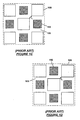
- FIG. 1A shows a conventional honeycomb wall-flow filter 100 having an inlet end 102, an outlet end 104, and an array of interconnecting porous walls 106 extending longitudinally from the inlet end 102 to the outlet end 104.
- the interconnecting porous walls 106 define a grid of inlet channels 108 and outlet channels 110.
- the outlet channels 110 are end-plugged with filler material 112 while inlet channels 108 are not end-plugged.
- the inlet channels 108 are end-plugged with filler material while the outlet channels 110 are not end-plugged.
- FIG. 1B shows a close-up view of the cell structure used in the honeycomb filter.
- the porous walls 106 defining the inlet and outlet channels (or cells) 108, 110 are straight, and the inlet and outlet cells 108, 110 have a square cross-section and equal hydraulic diameter.
- diesel exhaust flows into the honeycomb filter 100 through the unplugged ends of the inlet channels 108 and exits the honeycomb filter through the unplugged ends of the outlet channels 110.
- the diesel exhaust is forced from the inlet channels 108 into the outlet channels 110 through the porous walls 106.
- soot and ash particles accumulate on the porous walls 106, decreasing the effective flow area of the inlet channels 108.
- the decreased effective flow area creates a pressure drop across the honeycomb filter, which leads to a gradual rise in back pressure against the diesel engine. When the pressure drop becomes unacceptable, thermal regeneration is used to remove the soot particles trapped in the honeycomb filter.
- the ash particles which include metal oxide impurities, additives from lubrication oils, sulfates and the like, are not combustible and cannot be removed by thermal regeneration. During thermal regeneration, excessive temperature spikes can occur, which can thermally shock, crack, or even melt, the honeycomb filter.
- the honeycomb filter has sufficient structural strength to withstand thermal regeneration. To avoid the need for frequent thermal regeneration, it is also desirable that the honeycomb filter has a high capacity for storing soot and ash particles.
- the effective flow area of the inlet channels can easily become much smaller than that of the outlet channels, creating a large pressure drop across the honeycomb filter.
- One solution that has been proposed to reducing this pressure drop involves making the hydraulic diameter (or effective cross-sectional flow area) of the inlet channels larger than that of the outlet channels. In this way, as soot and ash particles accumulate on the inlet portion of the porous walls, the effective flow area of the inlet channels will tend to equalize with that of the outlet channels.
- the hydraulic diameter of the inlet cells 108 can be made larger than the outlet cells 110 by reducing the hydraulic diameter of the outlet cells 110.
- Figure 1C shows the honeycomb cell structure of Figure 1B after reducing the hydraulic diameter of the outlet cell 110 such that the outlet cell 110 now has a smaller hydraulic diameter in comparison to the inlet cell 108.
- Another modification that can be made is to increase the hydraulic diameter of the inlet cells 108. This modification has the advantage of increasing the effective surface area available for collecting soot and ash particles in the inlet portion of the honeycomb filter, which ultimately increases the overall storage capacity of the honeycomb filter.
- Figure 1D shows the honeycomb cell structure of Figure 1C after increasing the hydraulic diameter of the inlet cell 108.
- any increase in the hydraulic diameter of the inlet cell 108 would produce a corresponding decrease in the thickness of the wall between the adjacent corners of inlet cells 108 (compare t 2 in Figure 1D with t 1 in Figure 1C ).
- the structural strength of the honeycomb filter decreases, making the honeycomb filter more susceptible to thermal shock and cracking during thermal regeneration.
- JP 1 172 155 S discloses a honeycomb filter comprising an array of interconnecting porous walls which define an array of first channels and second channels, the first channels being bordered on their sides by the second channels and having a larger hydraulic diameter than the second channels, the first channels having a square cross-section.
- US-A-5 256 054 discloses an extrusion die assembly for making a honeycomb filter.
- WO-A2-03/020407 discloses a honeycomb filter comprising the features of the preamble of claim 1.
- the invention relates to a honeycomb filter which comprises an array of interconnecting porous walls that define an array of first channels and second channels.
- the first channels are bordered on their sides by the second channels and have a larger hydraulic diameter than the second channels.
- the first channels have a square cross-section, with corners of the first channels having a shape such that the thickness of the porous walls adjoining corners of the first channels is comparable to the thickness of the porous walls adjoining edges of the first and the second channels.
- the invention in another aspect, relates to a honeycomb filter which comprises an array of interconnecting porous walls that define an array of first channels having a square cross-section and second channels having a square cross-section.
- the first channels are bordered on their edges by the second channels.
- the edges of the first channels are aligned with edges of the bordering second channels.
- the first channels have a larger hydraulic diameter than the second channels.
- the invention in yet another aspect, relates to an extrusion die assembly for making a honeycomb filter which comprises a cell forming die having a central region and a peripheral region.
- the central region comprises an array of discharge slots cut to define an array of first and second pins and an array of first feedholes in communication with the array of discharge slots.
- the peripheral region comprises at least a second feedhole.
- the first pins have a larger cross-sectional area than the second pins.
- the cross-sectional shape of the first pins is selected such that the width of the discharge slots is substantially uniform.
- the extrusion die assembly also includes a skin forming mask mounted coaxially with the cell forming die and radially spaced from the cell forming die so as to define a skin slot that is in selective communication with the at least second feedhole.
- Figure 1A is a perspective view of a prior-art honeycomb wall-flow filter.
- Figure 1B shows a standard honeycomb cell structure having inlet and outlet cells with equal hydraulic diameter.
- Figure 1C shows the honeycomb cell structure of Figure 1B after reducing the hydraulic diameter of the outlet cells.
- Figure 1D shows the honeycomb cell structure of Figure 1C after increasing the hydraulic diameter of the inlet cells.
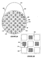
- Figure 2A is a perspective view of a honeycomb wall-flow filter according to an embodiment of the invention.
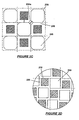
- Figure 2B shows a honeycomb cell structure having inlet cells and outlet cells with unequal hydraulic diameters and the inlet cells with filleted corners according to one embodiment of the invention.
- Figure 2C shows a honeycomb cell structure having inlet cells and outlet cells with unequal hydraulic diameters and the inlet cells with beveled corners according to another embodiment of the invention.
- Figure 2D shows a honeycomb cell structure having inlet and outlet cells with unequal hydraulic diameters and aligned edges not according to the invention.
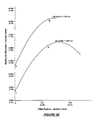
- Figure 2E is a graph of hydraulic diameter of a cell as a function of fillet radius and cell width.
- Figure 3 is a cross-section of an extrusion die assembly according to one embodiment of the invention.
- FIG. 2A shows a honeycomb wall-flow filter 200 according to an embodiment of the invention.
- the honeycomb filter 200 has a columnar body 202 whose cross-sectional shape is defined by a skin (or peripheral wall) 204.
- the profile of the skin 204 is typically circular or elliptical, but the invention is not limited to any particular skin profile.
- the columnar body 202 has an array of interconnecting porous walls 206, which intersect with the skin 204.
- the porous walls 206 define a grid of inlet channels 208 and outlet channels 210 in the columnar body 202.
- the inlet and outlet channels 208, 210 extend longitudinally along the length of the columnar body 202.
- the columnar body 202 is made by extrusion.
- the columnar body 202 is made of a ceramic material, such as cordierite or silicon carbide, but could also be made of other extrudable materials, such as glass, glass-ceramics, plastic, and metal.
- the honeycomb filter 200 has an inlet end 212 for receiving flow, e.g., exhaust gas flow, and an outlet end 214 through which filtered flow can exit the honeycomb filter.
- end portions of the outlet channels 210 are plugged with filler material 216 while the end portions of the inlet channels 208 are not plugged.
- the filler material 216 is made of a ceramic material, such as cordierite or silicon carbide.
- end portions of inlet channels 208 are plugged with filler material while the end portions of the outlet channels 210 are not plugged. Partial cells near the periphery of the skin 204 are typically plugged with filler material.
- the interconnected porous walls 206 allow flow from the inlet channels 208 into the outlet channels 210.
- the porosity of the porous walls 206 can be variable. In general, the porosity should be such that the structural integrity of the honeycomb filter is not compromised.
- the porous walls 206 may incorporate pores having mean diameters in the range of 1 to 60 ⁇ m, more preferably in a range from 10 to 50 ⁇ m.
- FIG. 2B shows a close-up view of the cell structure of the honeycomb filter 200.
- Each inlet cell 208 is bordered by outlet cells 210 and vice versa.
- the inlet cells 208 are made to have a larger hydraulic diameter than the outlet cells 210.
- the outlet cells 210 have a square geometry.
- the inlet cells 208 also have a square geometry, but the corners of the square include fillets 218.
- One purpose of the fillets 218 is to make the thickness (t 3 ) between the adjacent corners of the inlet cells 208 comparable to the thickness (t 4 ) between the inlet cells 208 and the outlet cells 210.
- the thickness t 3 is in a range of about 0.8 to 1.2 times the thickness t 4 .
- the radius of the fillets 218 is selected such that the thickness of the porous walls is substantially uniform around the cells.
- the radius of the fillets 218 may also be selected such that hydraulic diameter of the inlet cells 208 is maximized for a selected cell density and closed frontal area.
- Table 1 below shows examples of cell structures having a cell density of 200 cells/in 2 (about 31 cells/cm 2 ) and a closed frontal area of 47%.
- Cell structures A and B are specific examples of the inventive cell structure shown in Figure 2B .
- Cell structures C and D are specific examples of the prior-art cell structure shown in Figure 1C .
- the hydraulic diameters of the inlet cells of the inventive cell structures A and B are larger than the hydraulic diameters of the inlet cells of the prior-art cell structures C and D, respectively.
- the larger hydraulic diameters of the cell structures A and B are achieved while maintaining the same cell density and closed frontal area as that of the prior-art cell structures C and D.
- Figure 2E shows how hydraulic diameter varies as a function of fillet radius for a given cell width.
- the position of the cell structures A, B, C, and D are indicated on the graph.
- the graph shows that hydraulic diameter has a non-linear relationship with fillet radius.
- the inlet cells can be made to have the fillet radius corresponding to the maximum hydraulic diameter achievable for a selected cell width.
- the present invention is not limited to inclusion of fillets 218 at the corners of the inlet cells 208.
- the corners of the inlet cells 208 can also be beveled.
- Figure 2C shows a cell structure where the corners of the inlet cells 208 include bevels 220.
- the inlet cells 208 have also been enlarged such that the edges of (diagonally) adjacent inlet cells 208 are substantially aligned. This increases the overall storage capacity of the honeycomb filter while allowing good flow rates through the honeycomb filter to be maintained.
- the bevels 220 (or fillets if used instead of bevels) enable uniformly thick porous walls 206 to be provided around the cells.
- porous walls 206 are not straight. This leads to an increase in the thermal shock resistance of the honeycomb structure.
- portions of the porous walls e.g., porous wall 206a, are common to only the inlet cells 208. These porous wall portions that are common to only the inlet cells 208 could facilitate transfer of heat from one inlet cell to another during thermal regeneration.
- the fillets and bevels can be used to achieve a substantially uniform porous wall thickness throughout the honeycomb filter while maintaining a desired closed frontal area, cell density, and ratio of hydraulic diameter of inlet cell to outlet cell.
- the ratio of hydraulic diameter of inlet cell to outlet cell is in a range from 1.1 to 2.0, preferably 1.3 to 2.0, more preferably 1.7 to 2.0.
- the thickness of the interconnecting porous walls can vary upwards from the minimum dimension of about 0.002 in. (0.05 mm) providing structural integrity, but is generally less than about 0.060 in (1.5 mm) to minimize filter volume.
- Figure 2D shows a cell structure not according to the present invention where the edges of the inlet cells 208 are aligned with edges of the outlet cells 210 and the thickness of the porous walls 206 is uniform throughout the honeycomb filter without the use of a bevel or fillet at the corners of the inlet cells 208.
- a fillet or bevel to the corners of the inlet cells 208 can further improve the structural strength of the honeycomb filter.
- the porous walls 206 in this embodiment are even less straight than the porous walls in the embodiments previously described, leading to further improvement in thermal shock resistance.
- FIG. 3 shows a vertical cross-section of an extrusion die assembly 300.
- the extrusion die assembly 300 includes a cell forming die 302 and a skin forming mask 304.
- the cell forming die 300 is used to form the interconnecting porous walls that define the inlet and outlet cells of the honeycomb filter.
- the cell forming die 302 cooperate with the skin forming mask 304 to define the shape and thickness of the skin of the honeycomb filter.
- the cell forming die 302 has a central region 306.
- An array of discharge slots 308 is cut in the central region 306 to define an array of inlet and outlet pins 310, 312.
- the transverse cross-section of the inlet and outlet pins 310, 312 is square, with each corner of the inlet pins 310 including a fillet or bevel.
- the central region 306 of the cell forming die 302 further includes an array of central feedholes 314, which extend from the inlet face 315 of the die to the array of discharge slots 308.
- the central feedholes 314 supply batch material to the discharge slots 308.
- the size and location of the central feedholes 314 relative to the discharge slots 308 are selected to achieve a desired flow rate through the discharge slots 308.
- a central feedhole 308 may correspond to each or every other discharge slot 308 or may correspond to each or every other intersection of the discharge slots 308.
- the cell forming die 302 also includes a peripheral region 316 formed contiguous with the central region 306.
- the peripheral region 316 provides a mounting surface 318 for the skin forming mask 304 and includes feedholes 318 for feeding batch material to spaces around the cell forming die 302.
- a shim 320 is interposed between the mounting surface 318 and the skin forming mask 304 to define a skin forming reservoir 322 between the peripheral region 316 and the skin forming mask 304.
- the feedholes 318 in the peripheral region 316 supply batch material to the skin forming reservoir 322.
- the skin forming mask 304 is radially spaced from the central region 306 to define a skin slot 324, which is in communication with the skin forming reservoir 322. Batch material is extruded through the skin slot 324 to form the skin of the honeycomb filter.
- the volume of the reservoir 322 can be adjusted to control the rate at which batch material is supplied into the skin slot 324.
- batch material is fed into the feedholes 314, 318 in the cell forming die 302 and extruded through the discharge slots 308 and the skin forming slot 324.
- the volume of the batch material in the skin forming reservoir 322 is dependent on the extent of the radial overhang of the skin forming mask 304 over the skin forming reservoir 322.
- the rate of flow of batch material into the skin forming slot determines the character of the skin, while the rate of flow of batch material into the discharge slots determine the character of the porous walls.
- the extrusion die assembly described above can be manufactured using existing methods for making extrusion dies.
- the cell forming die may be made by machining holes in a lower portion of a block that is made of a machinable material. These holes would serve as feedholes.
- a process such as plunge electrical discharge machining can be used to cut the discharge slots in the upper portion of the block. Pins remain on the upper portion of the block after the slots are cut.
- the pins at the periphery of the block can be shortened or completely removed to provide a mounting surface for the skin forming mask.
- the discharge slots could have any of the geometries described above in conjunction with the cell structure of the honeycomb filter.
Landscapes
- Chemical & Material Sciences (AREA)
- Engineering & Computer Science (AREA)
- Physics & Mathematics (AREA)
- Geometry (AREA)
- Chemical Kinetics & Catalysis (AREA)
- Ceramic Engineering (AREA)
- Mechanical Engineering (AREA)
- Manufacturing & Machinery (AREA)
- General Engineering & Computer Science (AREA)
- Combustion & Propulsion (AREA)
- Materials Engineering (AREA)
- Structural Engineering (AREA)
- Organic Chemistry (AREA)
- Filtering Materials (AREA)
- Press-Shaping Or Shaping Using Conveyers (AREA)
- Filtering Of Dispersed Particles In Gases (AREA)
- Networks Using Active Elements (AREA)
- Piezo-Electric Or Mechanical Vibrators, Or Delay Or Filter Circuits (AREA)
Claims (7)
- Wabenfilter, umfassend ein Array von verbindenden porösen Wänden (206), die ein Array von ersten Kanälen (208) und zweiten Kanälen (210) definieren, wobei an die ersten Kanäle (208) auf ihren Seiten die zweiten Kanäle (210) angrenzen und sie einen größeren hydraulischen Durchmesser als die zweiten Kanäle (210) aufweisen, wobei die ersten Kanäle (208) einen quadratischen Querschnitt aufweisen, wobei die Ecken der ersten Kanäle (208) eine Gestalt derart aufweisen, dass die Dicke (t3) der Ecken der ersten Kanäle (208) benachbarten porösen Wände in einem Bereich vom 0,8- bis 1,2-fachen der Dicke (t4) der Kanten der ersten und zweiten Kanäle (208, 210) benachbarten porösen Wände liegt, wobei ein Verhältnis des hydraulischen Durchmessers der ersten Kanäle (208) zu dem hydraulischen Durchmesser der zweiten Kanäle (210) in einem Bereich von 1,1 bis 2,0 liegt, dadurch gekennzeichnet, dass die Gestalt der ersten Kanäle (208) eine Abrundung (218) oder eine Abschrägung (220) an den Ecken der ersten Kanäle (208) beinhaltet.
- Wabenfilter nach Anspruch 1, dadurch gekennzeichnet, dass Kanten von diagonal benachbarten ersten Kanälen (208) im Wesentlichen ausgerichtet sind.
- Wabenfilter nach Anspruch 1, dadurch gekennzeichnet, dass die zweiten Kanäle (210) einen quadratischen Querschnitt aufweisen.
- Wabenfilter nach Anspruch 1, dadurch gekennzeichnet, dass das Verhältnis des hydraulischen Durchmessers der ersten Kanäle (208) zu dem hydraulischen Durchmesser der zweiten Kanäle (210) in einem Bereich von 1,7 bis 2,0 liegt.
- Extrusionsdüsenbaugruppe zum Herstellen eines Wabenfilters (200) gemäß einem der Ansprüche 1 bis 4, umfassend:eine Zellenausbildungsdüse (302) mit einem zentralen Gebiet (306) und einem peripheren Gebiet (316), wobei das zentrale Gebiet (306) ein Array von Austragsschlitzen (308), die so geschnitten sind, dass sie ein Array von ersten und zweiten Pins (310, 312) definieren, und ein Array von ersten Zuführlöchern (314) in Kommunikation mit dem Array von Austragsschlitzen umfasst, wobei das periphere Gebiet (316) mindestens ein zweites Zuführloch (318) umfasst, wobei die ersten Pins eine größere Querschnittsfläche als die zweiten Pins aufweisen, wobei eine Querschnittsgestalt der ersten Pins derart ausgewählt ist, dass die Breite der Austragsschlitze im Wesentlichen gleichförmig ist, wobei die Querschnittsgestalt der ersten Pins ein Quadrat mit abgerundeten oder abgeschrägten Ecken beinhaltet;und eine Hautausbildungsmaske (304), die koaxial zu der Zellenausbildungsdüse montiert und radial von der Zellenausbildungsdüse beabstandet ist, um einen Hautschlitz (324) zu definieren, der mit dem mindestens zweiten Zuführloch (318) in selektiver Kommunikation steht.
- Extrusionsdüsenbaugruppe nach Anspruch 5, dadurch gekennzeichnet, dass sie einen Hautbehälter (322) umfasst, der zwischen der Zellenausbildungsdüse (302) und der Hautausbildungsmaske (304) definiert ist, wobei der Hautbehälter (322) mit dem mindestens zweiten Zuführloch und dem Hautschlitz (324) in Kommunikation steht.
- Extrusionsdüsenbaugruppe nach Anspruch 6, dadurch gekennzeichnet, dass ein Volumen des Hautbehälters (322) justiert werden kann, um die Strömungsrate von Chargenmaterial zu dem Hautschlitz zu steuern.
Applications Claiming Priority (2)
| Application Number | Priority Date | Filing Date | Title |
|---|---|---|---|
| US10/671,166 US7247184B2 (en) | 2003-09-25 | 2003-09-25 | Asymmetric honeycomb wall-flow filter having improved structural strength |
| PCT/US2004/030406 WO2005030365A1 (en) | 2003-09-25 | 2004-09-17 | Asymmetric honeycomb wall-flow filter having improved structural strength |
Publications (3)
| Publication Number | Publication Date |
|---|---|
| EP1663447A1 EP1663447A1 (de) | 2006-06-07 |
| EP1663447A4 EP1663447A4 (de) | 2007-06-20 |
| EP1663447B1 true EP1663447B1 (de) | 2010-05-26 |
Family
ID=34376092
Family Applications (1)
| Application Number | Title | Priority Date | Filing Date |
|---|---|---|---|
| EP04784303A Revoked EP1663447B1 (de) | 2003-09-25 | 2004-09-17 | Asymmetrischer wabenwandstromfilter mit verbesserter formfestigkeit |
Country Status (7)
| Country | Link |
|---|---|
| US (1) | US7247184B2 (de) |
| EP (1) | EP1663447B1 (de) |
| JP (1) | JP2007519505A (de) |
| CN (2) | CN101386214B (de) |
| AT (1) | ATE468904T1 (de) |
| DE (1) | DE602004027391D1 (de) |
| WO (1) | WO2005030365A1 (de) |
Families Citing this family (70)
| Publication number | Priority date | Publication date | Assignee | Title |
|---|---|---|---|---|
| DE602004011997T2 (de) * | 2003-06-05 | 2009-02-26 | Ibiden Co., Ltd., Ogaki | Wabenkörperstruktur |
| US7247184B2 (en) | 2003-09-25 | 2007-07-24 | Corning Incorporated | Asymmetric honeycomb wall-flow filter having improved structural strength |
| US7601194B2 (en) * | 2003-09-25 | 2009-10-13 | Corning Incorporated | Asymmetric honeycomb wall-flow filter having improved structural strength |
| US7393377B2 (en) | 2004-02-26 | 2008-07-01 | Ngk Insulators, Ltd. | Honeycomb filter and exhaust gas treatment apparatus |
| CN101263567A (zh) * | 2005-07-30 | 2008-09-10 | 康宁股份有限公司 | 具有不均匀单元几何形状的蜂窝混合型电容器 |
| DE102005044765A1 (de) * | 2005-09-20 | 2007-03-29 | Robert Bosch Gmbh | Filterelement und Filter zur Abgasnachbehandlung |
| DE102006035053A1 (de) * | 2005-09-20 | 2007-03-22 | Robert Bosch Gmbh | Filterelement und Rußfilter mit geometrisch ähnlichen Kanälen |
| DE102005047598A1 (de) * | 2005-10-05 | 2007-04-12 | Robert Bosch Gmbh | Filterelement und Filter zur Abgasnachbehandlung |
| US20100133193A1 (en) * | 2007-02-14 | 2010-06-03 | Honeywell International, Inc. | Diesel sulfur filter-nanoadsorber and method of filtering a liquid fuel |
| WO2008117559A1 (ja) * | 2007-03-28 | 2008-10-02 | Ngk Insulators, Ltd. | ハニカムフィルタ |
| US8814974B2 (en) * | 2007-08-24 | 2014-08-26 | Corning Incorporated | Thin-walled porous ceramic wall-flow filter |
| PL2188228T3 (pl) * | 2007-08-31 | 2019-05-31 | Corning Inc | Wyrób z kordierytu o strukturze plastra miodu i sposób wytwarzania |
| KR101457145B1 (ko) | 2007-11-08 | 2014-10-31 | 주식회사 칸세라 | 비대칭형 채널구조를 갖는 세라믹 성형체의 제조방법 |
| EP2065575B1 (de) * | 2007-11-29 | 2012-08-15 | Corning Incorporated | Wandfluss-Wabenfilter mit hoher Speicherkapazität und geringem Gegendruck |
| JP2009243274A (ja) * | 2008-03-28 | 2009-10-22 | Mazda Motor Corp | パティキュレートフィルタ |
| US8187353B2 (en) * | 2009-01-21 | 2012-05-29 | Corning Incorporated | Filtration structures for improved particulate filter performance |
| US8231701B2 (en) * | 2009-01-21 | 2012-07-31 | Corning Incorporated | Particulate filters and methods for regenerating particulate filters |
| US20100301515A1 (en) * | 2009-05-29 | 2010-12-02 | Thomas William Brew | Honeycomb Extrusion Die Apparatus And Methods |
| US20110206896A1 (en) * | 2010-02-25 | 2011-08-25 | Mark Lee Humphrey | Ceramic Honeycomb Body And Process For Manufacture |
| EP2368619B1 (de) * | 2010-03-26 | 2014-06-25 | Imerys | Keramische Wabenstrukturen |
| US9856177B2 (en) | 2010-05-28 | 2018-01-02 | Corning Incorporated | Cordierite porous ceramic honeycomb articles |
| US9334191B2 (en) | 2010-05-28 | 2016-05-10 | Corning Incorporated | Methods for forming ceramic honeycomb articles |
| US8999224B2 (en) * | 2010-11-30 | 2015-04-07 | Corning Incorporated | Cordierite porous ceramic honeycomb articles with delayed microcrack evolution |
| US8865084B2 (en) | 2011-11-30 | 2014-10-21 | Corning Incorporated | Pass-through catalytic substrate including porous ceramic beveled corner portions and methods |
| USD744078S1 (en) | 2011-12-07 | 2015-11-24 | Sumitomo Chemical Company, Limited | Particulate filter |
| CN103157387A (zh) * | 2011-12-14 | 2013-06-19 | 南京髙谦功能材料科技有限公司 | 基于壁流式蜂窝陶瓷的钯或钯合金膜及其制备方法和应用 |
| DE102012008523A1 (de) | 2012-05-02 | 2013-11-07 | Man Truck & Bus Ag | Abgasnachbehandlungssystem |
| WO2013186922A1 (ja) | 2012-06-15 | 2013-12-19 | イビデン株式会社 | ハニカムフィルタ |
| WO2013186923A1 (ja) | 2012-06-15 | 2013-12-19 | イビデン株式会社 | ハニカムフィルタ |
| WO2014054159A1 (ja) * | 2012-10-04 | 2014-04-10 | イビデン株式会社 | ハニカムフィルタ |
| JP5972816B2 (ja) * | 2013-03-22 | 2016-08-17 | 日本碍子株式会社 | ハニカム構造体 |
| JP6014526B2 (ja) * | 2013-03-22 | 2016-10-25 | 日本碍子株式会社 | ハニカム構造体 |
| JP6267452B2 (ja) * | 2013-07-31 | 2018-01-24 | イビデン株式会社 | ハニカムフィルタ |
| JP6239305B2 (ja) * | 2013-07-31 | 2017-11-29 | イビデン株式会社 | ハニカムフィルタ |
| JP6239306B2 (ja) | 2013-07-31 | 2017-11-29 | イビデン株式会社 | ハニカムフィルタ |
| JP6239303B2 (ja) | 2013-07-31 | 2017-11-29 | イビデン株式会社 | ハニカムフィルタ |
| JP6239307B2 (ja) | 2013-07-31 | 2017-11-29 | イビデン株式会社 | ハニカムフィルタ |
| JP6239304B2 (ja) | 2013-07-31 | 2017-11-29 | イビデン株式会社 | ハニカムフィルタ |
| US9808794B2 (en) | 2013-09-23 | 2017-11-07 | Corning Incorporated | Honeycomb ceramic substrates, honeycomb extrusion dies, and methods of making honeycomb ceramic substrates |
| GB2520776A (en) | 2013-12-02 | 2015-06-03 | Johnson Matthey Plc | Wall-flow filter comprising catalytic washcoat |
| JP6259327B2 (ja) * | 2014-03-13 | 2018-01-10 | 日本碍子株式会社 | ハニカム構造体 |
| WO2016158420A1 (ja) * | 2015-03-31 | 2016-10-06 | 株式会社小松製作所 | ハニカムフィルタ |
| GB2542654B (en) | 2015-06-28 | 2019-12-04 | Johnson Matthey Plc | Catalytic wall-flow filter having a membrane |
| JP6594149B2 (ja) * | 2015-10-05 | 2019-10-23 | 株式会社キャタラー | 排ガス浄化装置 |
| JP6297767B2 (ja) * | 2016-03-24 | 2018-03-20 | 株式会社キャタラー | 排ガス浄化装置 |
| US9879581B2 (en) * | 2016-03-25 | 2018-01-30 | Caterpillar Inc. | After-treatment system |
| MX2018012815A (es) * | 2016-04-22 | 2019-09-04 | Corning Inc | Estructuras de panal de salida rectangular, filtros de material particulado, dados de extrusión y método de fabricación de los mismos. |
| GB2558371B (en) | 2016-10-28 | 2021-08-18 | Johnson Matthey Plc | Catalytic wall-flow filter with partial surface coating |
| JP6729356B2 (ja) * | 2016-12-27 | 2020-07-22 | 株式会社デンソー | 多孔質ハニカムフィルタ |
| GB2562160B (en) | 2017-03-20 | 2021-06-23 | Johnson Matthey Plc | Catalytic wall-flow filter with an ammonia slip catalyst |
| GB2562161A (en) | 2017-03-20 | 2018-11-07 | Johnson Matthey Plc | Rear on-wall design SCRF |
| JP2018167200A (ja) * | 2017-03-30 | 2018-11-01 | 日本碍子株式会社 | ハニカムフィルタ |
| JP6862245B2 (ja) * | 2017-03-30 | 2021-04-21 | 日本碍子株式会社 | ハニカムフィルタ |
| CN108278142A (zh) * | 2017-12-27 | 2018-07-13 | 山东国瓷功能材料股份有限公司 | 一种蜂窝陶瓷堵孔结构 |
| CN108286465A (zh) * | 2017-12-27 | 2018-07-17 | 山东国瓷功能材料股份有限公司 | 一种抗热震非对称蜂窝陶瓷壁流式过滤器 |
| WO2019213569A1 (en) * | 2018-05-04 | 2019-11-07 | Corning Incorporated | High isostatic strength honeycomb structures and extrusion dies therefor |
| EP3844123A1 (de) | 2018-08-31 | 2021-07-07 | Corning Incorporated | Mit cordierit-indialit-pseudobrookit strukturierte keramikkörper, gemengezusammensetzungen und verfahren zur herstellung keramischer körper daraus |
| US11975285B2 (en) | 2018-11-15 | 2024-05-07 | Corning Incorporated | Tilted cell honeycomb body, extrusion die and method of manufacture thereof |
| EP3880342B1 (de) | 2018-11-16 | 2024-06-12 | Corning Incorporated | Cordierithaltiger keramischer körper, chargenzusammensetzungsmischungen und verfahren zur herstellung von cordierithaltigen keramischen körpern |
| EP3880340A1 (de) * | 2018-11-16 | 2021-09-22 | Corning Incorporated | Wabenkörper mit einer anordnung von kanälen mit unterschiedlichen hydraulischen durchmessern und verfahren zu ihrer herstellung |
| CN113329806B (zh) * | 2018-11-16 | 2022-12-02 | 康宁股份有限公司 | 具有一定范围的水力直径的贯穿通道阵列的蜂窝体 |
| CN110107379A (zh) * | 2019-06-10 | 2019-08-09 | 常州浩蔚环保科技有限公司 | 一种蜂窝陶瓷颗粒捕捉器的非对称倒角结构 |
| CN110253721A (zh) * | 2019-07-03 | 2019-09-20 | 南京柯瑞特种陶瓷股份有限公司 | 一种非对称结构蜂窝陶瓷、模具及模具的加工方法 |
| GB201911702D0 (en) | 2019-08-15 | 2019-10-02 | Johnson Matthey Plc | Particulate filters |
| KR20240018530A (ko) | 2021-08-27 | 2024-02-13 | 존슨 맛쎄이 퍼블릭 리미티드 컴파니 | 모놀리스 물품 상의 무기 산화물 코팅의 형성 방법 |
| EP4335547A1 (de) | 2022-09-12 | 2024-03-13 | Johnson Matthey Public Limited Company | Verfahren zur herstellung einer anorganischen oxidbeschichtung auf einem monolithischen artikel |
| CN115573793A (zh) * | 2022-09-30 | 2023-01-06 | 兰德森排放技术有限公司 | 颗粒过滤器和挤出模具 |
| EP4374952A1 (de) | 2022-11-28 | 2024-05-29 | Johnson Matthey Public Limited Company | Beschichtungen auf einem monolithischen artikel |
| EP4400202A1 (de) | 2023-01-16 | 2024-07-17 | Johnson Matthey Public Limited Company | Beschichtungen auf einem monolithischen artikel |
| EP4624045A1 (de) | 2024-03-28 | 2025-10-01 | Johnson Matthey Public Limited Company | Verfahren zur herstellung einer anorganischen oxidbeschichtung auf einem monolithischen artikel |
Family Cites Families (43)
| Publication number | Priority date | Publication date | Assignee | Title |
|---|---|---|---|---|
| FR789327A (fr) | 1934-04-27 | 1935-10-26 | Ig Farbenindustrie Ag | Agents propres à former de la mousse avec l'air et utilisables comme extincteurs d'incendie |
| GB2064360B (en) * | 1979-12-03 | 1984-05-16 | Gen Motors Corp | Ceramic filters for diesel exhaust particulates and methods for making such filters |
| CA1145270A (en) | 1979-12-03 | 1983-04-26 | Morris Berg | Ceramic filters for diesel exhaust particulates and methods of making |
| US4276071A (en) | 1979-12-03 | 1981-06-30 | General Motors Corporation | Ceramic filters for diesel exhaust particulates |
| US4335023A (en) | 1980-01-24 | 1982-06-15 | Engelhard Corporation | Monolithic catalyst member and support therefor |
| SE433504B (sv) | 1980-02-22 | 1984-05-28 | Asea Atom Ab | Sett att behandla den invendiga ytan av ett ror av en zirkoniumbaserad legering fore applicering av skyddsskikt |
| US4329162A (en) | 1980-07-03 | 1982-05-11 | Corning Glass Works | Diesel particulate trap |
| US4420316A (en) | 1982-02-22 | 1983-12-13 | Corning Glass Works | Filter apparatus and method of making it |
| US4416676A (en) * | 1982-02-22 | 1983-11-22 | Corning Glass Works | Honeycomb filter and method of making it |
| US4417908A (en) * | 1982-02-22 | 1983-11-29 | Corning Glass Works | Honeycomb filter and method of making it |
| US4521532A (en) | 1984-04-23 | 1985-06-04 | General Motors Corporation | Monolithic catalytic converter for improved thermal performance |
| JPS61424A (ja) | 1984-06-12 | 1986-01-06 | Nippon Denso Co Ltd | セラミツクフイルタ |
| JPS62234552A (ja) * | 1986-04-02 | 1987-10-14 | Mitsubishi Heavy Ind Ltd | 触媒構造体 |
| CN86209661U (zh) * | 1986-11-27 | 1987-12-12 | 中国有色金属工业总公司昆明贵金属研究所 | 蜂窝催化剂载体挤压成型模具 |
| JPH01172155A (ja) * | 1987-12-25 | 1989-07-07 | Hashimoto Denki Co Ltd | ベニヤ単板の整列方法および装置 |
| US5256054A (en) | 1990-11-30 | 1993-10-26 | Corning Incorporated | Method and apparatus for forming a uniform skin on a cellular substrate |
| US5219509A (en) * | 1990-11-30 | 1993-06-15 | Corning Incorporated | Method for forming a uniform skin on a cellular substrate |
| US5108685A (en) * | 1990-12-17 | 1992-04-28 | Corning Incorporated | Method and apparatus for forming an article with multi-cellular densities and/or geometries |
| JPH07124428A (ja) * | 1993-11-08 | 1995-05-16 | Noritake Co Ltd | モノリス型セラミックフィルター |
| CN1147210A (zh) * | 1994-12-27 | 1997-04-09 | 有限会社米卡子基文化会馆 | 多孔陶瓷过滤器、其制造方法及多孔陶瓷过滤器制造用挤出成型模具和使用该模具的挤出成型装置 |
| JP3080563B2 (ja) * | 1995-08-21 | 2000-08-28 | 日本碍子株式会社 | ハニカム構造体押出用ダイスの製造方法 |
| US5714228A (en) | 1995-12-18 | 1998-02-03 | General Motors Corporation | Ceramic catalytic converter substrate |
| EP0854123B1 (de) | 1996-08-07 | 2006-04-05 | Denso Corporation | Keramische wabenstruktur und verfahren zu deren herstellung |
| JPH10264125A (ja) | 1997-03-28 | 1998-10-06 | Ngk Insulators Ltd | セラミックハニカム構造体 |
| FR2789327B1 (fr) | 1999-02-09 | 2001-04-20 | Ecia Equip Composants Ind Auto | Structure de filtration poreuse et dispositif de depollution la comportant |
| DE10037403A1 (de) | 2000-08-01 | 2002-02-14 | Daimler Chrysler Ag | Partikelfilter |
| US6464744B2 (en) | 2000-10-03 | 2002-10-15 | Corning Incorporated | Diesel particulate filters |
| US6508852B1 (en) | 2000-10-13 | 2003-01-21 | Corning Incorporated | Honeycomb particulate filters |
| CN2460187Y (zh) * | 2000-11-30 | 2001-11-21 | 佟泽林 | 壁流式蜂窝陶瓷过滤体 |
| US6570119B2 (en) | 2001-08-30 | 2003-05-27 | Corning Incorporated | Method of making extrusion die with varying pin size |
| US20030041730A1 (en) | 2001-08-30 | 2003-03-06 | Beall Douglas M. | Honeycomb with varying channel size |
| EP1462230B1 (de) * | 2001-11-05 | 2010-07-14 | Ngk Insulators, Ltd. | Düse zum formen eines wabenstrukturkörpers und verfahren zur herstellung desselben |
| CN2524917Y (zh) * | 2001-11-26 | 2002-12-11 | 黄麒荣 | 汽车空气滤清器的制造模具 |
| JP2004000896A (ja) | 2002-03-25 | 2004-01-08 | Ngk Insulators Ltd | ハニカムフィルター |
| USD505194S1 (en) | 2002-06-28 | 2005-05-17 | Ibiden Co., Ltd. | Particulate filter for diesel engine |
| USD523543S1 (en) | 2002-06-28 | 2006-06-20 | Ibiden Co., Ltd. | Particulate filter for diesel engine |
| CN1322909C (zh) * | 2002-09-13 | 2007-06-27 | 揖斐电株式会社 | 蜂窝状结构体 |
| WO2004024295A1 (ja) * | 2002-09-13 | 2004-03-25 | Ibiden Co., Ltd. | ハニカム構造体 |
| WO2004073969A2 (en) * | 2003-02-18 | 2004-09-02 | Corning Incorporated | Ceramic honeycomb body and process for manufacture |
| US7247184B2 (en) | 2003-09-25 | 2007-07-24 | Corning Incorporated | Asymmetric honeycomb wall-flow filter having improved structural strength |
| US7601194B2 (en) | 2003-09-25 | 2009-10-13 | Corning Incorporated | Asymmetric honeycomb wall-flow filter having improved structural strength |
| US7393377B2 (en) | 2004-02-26 | 2008-07-01 | Ngk Insulators, Ltd. | Honeycomb filter and exhaust gas treatment apparatus |
| US20050274097A1 (en) | 2004-06-14 | 2005-12-15 | Beall Douglas M | Diesel particulate filter with filleted corners |
-
2003
- 2003-09-25 US US10/671,166 patent/US7247184B2/en not_active Expired - Lifetime
-
2004
- 2004-09-17 DE DE602004027391T patent/DE602004027391D1/de not_active Expired - Lifetime
- 2004-09-17 AT AT04784303T patent/ATE468904T1/de not_active IP Right Cessation
- 2004-09-17 CN CN2008101259215A patent/CN101386214B/zh not_active Expired - Lifetime
- 2004-09-17 JP JP2006528065A patent/JP2007519505A/ja active Pending
- 2004-09-17 CN CNB2004800275973A patent/CN100546695C/zh not_active Expired - Lifetime
- 2004-09-17 EP EP04784303A patent/EP1663447B1/de not_active Revoked
- 2004-09-17 WO PCT/US2004/030406 patent/WO2005030365A1/en not_active Ceased
Also Published As
| Publication number | Publication date |
|---|---|
| EP1663447A4 (de) | 2007-06-20 |
| US20050066639A1 (en) | 2005-03-31 |
| JP2007519505A (ja) | 2007-07-19 |
| DE602004027391D1 (de) | 2010-07-08 |
| CN1856349A (zh) | 2006-11-01 |
| CN101386214A (zh) | 2009-03-18 |
| CN101386214B (zh) | 2012-03-21 |
| ATE468904T1 (de) | 2010-06-15 |
| WO2005030365A1 (en) | 2005-04-07 |
| US7247184B2 (en) | 2007-07-24 |
| CN100546695C (zh) | 2009-10-07 |
| EP1663447A1 (de) | 2006-06-07 |
Similar Documents
| Publication | Publication Date | Title |
|---|---|---|
| EP1663447B1 (de) | Asymmetrischer wabenwandstromfilter mit verbesserter formfestigkeit | |
| US7601194B2 (en) | Asymmetric honeycomb wall-flow filter having improved structural strength | |
| US6843822B2 (en) | Filter with varying cell channels | |
| US5731562A (en) | Method of making a ceramic catalytic converter open cell substrate with rounded corners | |
| US7807250B2 (en) | Wall-flow honeycomb filter with hexagonal channel symmetry | |
| EP1594687B1 (de) | Keramischer wabenkörper und herstellungsverfahren | |
| EP2241362A1 (de) | Teilweise dichtungsloses dpf | |
| US20050274097A1 (en) | Diesel particulate filter with filleted corners | |
| EP3576862B1 (de) | Strukturangeschlossene wabenkörper | |
| EP2010465A1 (de) | Bruchfeste keramikwabenstrukturen | |
| EP3414067B1 (de) | Extrusionskomponenten für wabenkörper | |
| EP3445472A2 (de) | Wabenstrukturen mit rechteckigem ausgang, partikelfilter, strangpressmatrizen und verfahren zur herstellung davon | |
| EP3727773B1 (de) | Extrusionsmatrize | |
| CN112368465B (zh) | 高均衡强度蜂窝结构及用于其的挤出模头 |
Legal Events
| Date | Code | Title | Description |
|---|---|---|---|
| PUAI | Public reference made under article 153(3) epc to a published international application that has entered the european phase |
Free format text: ORIGINAL CODE: 0009012 |
|
| 17P | Request for examination filed |
Effective date: 20060309 |
|
| AK | Designated contracting states |
Kind code of ref document: A1 Designated state(s): AT BE BG CH CY CZ DE DK EE ES FI FR GB GR HU IE IT LI LU MC NL PL PT RO SE SI SK TR |
|
| DAX | Request for extension of the european patent (deleted) | ||
| A4 | Supplementary search report drawn up and despatched |
Effective date: 20070518 |
|
| RIC1 | Information provided on ipc code assigned before grant |
Ipc: B01D 46/00 20060101AFI20050411BHEP Ipc: B32B 3/12 20060101ALI20070511BHEP Ipc: B01D 46/24 20060101ALI20070511BHEP |
|
| 17Q | First examination report despatched |
Effective date: 20071217 |
|
| GRAP | Despatch of communication of intention to grant a patent |
Free format text: ORIGINAL CODE: EPIDOSNIGR1 |
|
| GRAS | Grant fee paid |
Free format text: ORIGINAL CODE: EPIDOSNIGR3 |
|
| GRAA | (expected) grant |
Free format text: ORIGINAL CODE: 0009210 |
|
| AK | Designated contracting states |
Kind code of ref document: B1 Designated state(s): AT BE BG CH CY CZ DE DK EE ES FI FR GB GR HU IE IT LI LU MC NL PL PT RO SE SI SK TR |
|
| REG | Reference to a national code |
Ref country code: GB Ref legal event code: FG4D |
|
| REG | Reference to a national code |
Ref country code: CH Ref legal event code: EP |
|
| REG | Reference to a national code |
Ref country code: IE Ref legal event code: FG4D |
|
| REF | Corresponds to: |
Ref document number: 602004027391 Country of ref document: DE Date of ref document: 20100708 Kind code of ref document: P |
|
| REG | Reference to a national code |
Ref country code: NL Ref legal event code: VDEP Effective date: 20100526 |
|
| PG25 | Lapsed in a contracting state [announced via postgrant information from national office to epo] |
Ref country code: SE Free format text: LAPSE BECAUSE OF FAILURE TO SUBMIT A TRANSLATION OF THE DESCRIPTION OR TO PAY THE FEE WITHIN THE PRESCRIBED TIME-LIMIT Effective date: 20100526 |
|
| PG25 | Lapsed in a contracting state [announced via postgrant information from national office to epo] |
Ref country code: SI Free format text: LAPSE BECAUSE OF FAILURE TO SUBMIT A TRANSLATION OF THE DESCRIPTION OR TO PAY THE FEE WITHIN THE PRESCRIBED TIME-LIMIT Effective date: 20100526 Ref country code: AT Free format text: LAPSE BECAUSE OF FAILURE TO SUBMIT A TRANSLATION OF THE DESCRIPTION OR TO PAY THE FEE WITHIN THE PRESCRIBED TIME-LIMIT Effective date: 20100526 Ref country code: FI Free format text: LAPSE BECAUSE OF FAILURE TO SUBMIT A TRANSLATION OF THE DESCRIPTION OR TO PAY THE FEE WITHIN THE PRESCRIBED TIME-LIMIT Effective date: 20100526 |
|
| PG25 | Lapsed in a contracting state [announced via postgrant information from national office to epo] |
Ref country code: CY Free format text: LAPSE BECAUSE OF FAILURE TO SUBMIT A TRANSLATION OF THE DESCRIPTION OR TO PAY THE FEE WITHIN THE PRESCRIBED TIME-LIMIT Effective date: 20100526 Ref country code: GR Free format text: LAPSE BECAUSE OF FAILURE TO SUBMIT A TRANSLATION OF THE DESCRIPTION OR TO PAY THE FEE WITHIN THE PRESCRIBED TIME-LIMIT Effective date: 20100827 Ref country code: PL Free format text: LAPSE BECAUSE OF FAILURE TO SUBMIT A TRANSLATION OF THE DESCRIPTION OR TO PAY THE FEE WITHIN THE PRESCRIBED TIME-LIMIT Effective date: 20100526 |
|
| PG25 | Lapsed in a contracting state [announced via postgrant information from national office to epo] |
Ref country code: DK Free format text: LAPSE BECAUSE OF FAILURE TO SUBMIT A TRANSLATION OF THE DESCRIPTION OR TO PAY THE FEE WITHIN THE PRESCRIBED TIME-LIMIT Effective date: 20100526 Ref country code: NL Free format text: LAPSE BECAUSE OF FAILURE TO SUBMIT A TRANSLATION OF THE DESCRIPTION OR TO PAY THE FEE WITHIN THE PRESCRIBED TIME-LIMIT Effective date: 20100526 Ref country code: PT Free format text: LAPSE BECAUSE OF FAILURE TO SUBMIT A TRANSLATION OF THE DESCRIPTION OR TO PAY THE FEE WITHIN THE PRESCRIBED TIME-LIMIT Effective date: 20100927 Ref country code: EE Free format text: LAPSE BECAUSE OF FAILURE TO SUBMIT A TRANSLATION OF THE DESCRIPTION OR TO PAY THE FEE WITHIN THE PRESCRIBED TIME-LIMIT Effective date: 20100526 |
|
| PG25 | Lapsed in a contracting state [announced via postgrant information from national office to epo] |
Ref country code: SK Free format text: LAPSE BECAUSE OF FAILURE TO SUBMIT A TRANSLATION OF THE DESCRIPTION OR TO PAY THE FEE WITHIN THE PRESCRIBED TIME-LIMIT Effective date: 20100526 Ref country code: RO Free format text: LAPSE BECAUSE OF FAILURE TO SUBMIT A TRANSLATION OF THE DESCRIPTION OR TO PAY THE FEE WITHIN THE PRESCRIBED TIME-LIMIT Effective date: 20100526 Ref country code: CZ Free format text: LAPSE BECAUSE OF FAILURE TO SUBMIT A TRANSLATION OF THE DESCRIPTION OR TO PAY THE FEE WITHIN THE PRESCRIBED TIME-LIMIT Effective date: 20100526 Ref country code: BE Free format text: LAPSE BECAUSE OF FAILURE TO SUBMIT A TRANSLATION OF THE DESCRIPTION OR TO PAY THE FEE WITHIN THE PRESCRIBED TIME-LIMIT Effective date: 20100526 |
|
| PLBI | Opposition filed |
Free format text: ORIGINAL CODE: 0009260 |
|
| PLAX | Notice of opposition and request to file observation + time limit sent |
Free format text: ORIGINAL CODE: EPIDOSNOBS2 |
|
| 26 | Opposition filed |
Opponent name: YOUNG THOUGHT LIMITED Effective date: 20110225 |
|
| PG25 | Lapsed in a contracting state [announced via postgrant information from national office to epo] |
Ref country code: MC Free format text: LAPSE BECAUSE OF NON-PAYMENT OF DUE FEES Effective date: 20100930 |
|
| REG | Reference to a national code |
Ref country code: CH Ref legal event code: PL |
|
| REG | Reference to a national code |
Ref country code: DE Ref legal event code: R026 Ref document number: 602004027391 Country of ref document: DE Effective date: 20110225 |
|
| GBPC | Gb: european patent ceased through non-payment of renewal fee |
Effective date: 20100917 |
|
| PG25 | Lapsed in a contracting state [announced via postgrant information from national office to epo] |
Ref country code: CH Free format text: LAPSE BECAUSE OF NON-PAYMENT OF DUE FEES Effective date: 20100930 Ref country code: LI Free format text: LAPSE BECAUSE OF NON-PAYMENT OF DUE FEES Effective date: 20100930 Ref country code: IE Free format text: LAPSE BECAUSE OF NON-PAYMENT OF DUE FEES Effective date: 20100917 |
|
| PLAF | Information modified related to communication of a notice of opposition and request to file observations + time limit |
Free format text: ORIGINAL CODE: EPIDOSCOBS2 |
|
| PG25 | Lapsed in a contracting state [announced via postgrant information from national office to epo] |
Ref country code: GB Free format text: LAPSE BECAUSE OF NON-PAYMENT OF DUE FEES Effective date: 20100917 |
|
| PLBB | Reply of patent proprietor to notice(s) of opposition received |
Free format text: ORIGINAL CODE: EPIDOSNOBS3 |
|
| PG25 | Lapsed in a contracting state [announced via postgrant information from national office to epo] |
Ref country code: BG Free format text: LAPSE BECAUSE OF FAILURE TO SUBMIT A TRANSLATION OF THE DESCRIPTION OR TO PAY THE FEE WITHIN THE PRESCRIBED TIME-LIMIT Effective date: 20100526 Ref country code: HU Free format text: LAPSE BECAUSE OF FAILURE TO SUBMIT A TRANSLATION OF THE DESCRIPTION OR TO PAY THE FEE WITHIN THE PRESCRIBED TIME-LIMIT Effective date: 20101127 Ref country code: LU Free format text: LAPSE BECAUSE OF NON-PAYMENT OF DUE FEES Effective date: 20100917 |
|
| PG25 | Lapsed in a contracting state [announced via postgrant information from national office to epo] |
Ref country code: TR Free format text: LAPSE BECAUSE OF FAILURE TO SUBMIT A TRANSLATION OF THE DESCRIPTION OR TO PAY THE FEE WITHIN THE PRESCRIBED TIME-LIMIT Effective date: 20100526 |
|
| PGFP | Annual fee paid to national office [announced via postgrant information from national office to epo] |
Ref country code: FR Payment date: 20121001 Year of fee payment: 9 Ref country code: IT Payment date: 20120924 Year of fee payment: 9 |
|
| RDAF | Communication despatched that patent is revoked |
Free format text: ORIGINAL CODE: EPIDOSNREV1 |
|
| REG | Reference to a national code |
Ref country code: DE Ref legal event code: R064 Ref document number: 602004027391 Country of ref document: DE Ref country code: DE Ref legal event code: R103 Ref document number: 602004027391 Country of ref document: DE |
|
| PGFP | Annual fee paid to national office [announced via postgrant information from national office to epo] |
Ref country code: DE Payment date: 20120927 Year of fee payment: 9 |
|
| RDAG | Patent revoked |
Free format text: ORIGINAL CODE: 0009271 |
|
| STAA | Information on the status of an ep patent application or granted ep patent |
Free format text: STATUS: PATENT REVOKED |
|
| 27W | Patent revoked |
Effective date: 20130121 |
|
| REG | Reference to a national code |
Ref country code: DE Ref legal event code: R107 Ref document number: 602004027391 Country of ref document: DE Effective date: 20130926 |
|
| PG25 | Lapsed in a contracting state [announced via postgrant information from national office to epo] |
Ref country code: BG Free format text: LAPSE BECAUSE OF FAILURE TO SUBMIT A TRANSLATION OF THE DESCRIPTION OR TO PAY THE FEE WITHIN THE PRESCRIBED TIME-LIMIT Effective date: 20100826 |
|
| PG25 | Lapsed in a contracting state [announced via postgrant information from national office to epo] |
Ref country code: ES Free format text: LAPSE BECAUSE OF FAILURE TO SUBMIT A TRANSLATION OF THE DESCRIPTION OR TO PAY THE FEE WITHIN THE PRESCRIBED TIME-LIMIT Effective date: 20100906 |