EP1663447B1 - Asymmetric honeycomb wall-flow filter having improved structural strength - Google Patents
Asymmetric honeycomb wall-flow filter having improved structural strength Download PDFInfo
- Publication number
- EP1663447B1 EP1663447B1 EP04784303A EP04784303A EP1663447B1 EP 1663447 B1 EP1663447 B1 EP 1663447B1 EP 04784303 A EP04784303 A EP 04784303A EP 04784303 A EP04784303 A EP 04784303A EP 1663447 B1 EP1663447 B1 EP 1663447B1
- Authority
- EP
- European Patent Office
- Prior art keywords
- channels
- skin
- honeycomb filter
- array
- inlet
- Prior art date
- Legal status (The legal status is an assumption and is not a legal conclusion. Google has not performed a legal analysis and makes no representation as to the accuracy of the status listed.)
- Revoked
Links
Images


Classifications
-
- B—PERFORMING OPERATIONS; TRANSPORTING
- B01—PHYSICAL OR CHEMICAL PROCESSES OR APPARATUS IN GENERAL
- B01D—SEPARATION
- B01D46/00—Filters or filtering processes specially modified for separating dispersed particles from gases or vapours
- B01D46/24—Particle separators, e.g. dust precipitators, using rigid hollow filter bodies
- B01D46/2403—Particle separators, e.g. dust precipitators, using rigid hollow filter bodies characterised by the physical shape or structure of the filtering element
- B01D46/2418—Honeycomb filters
- B01D46/2451—Honeycomb filters characterized by the geometrical structure, shape, pattern or configuration or parameters related to the geometry of the structure
- B01D46/247—Honeycomb filters characterized by the geometrical structure, shape, pattern or configuration or parameters related to the geometry of the structure of the cells
-
- B—PERFORMING OPERATIONS; TRANSPORTING
- B01—PHYSICAL OR CHEMICAL PROCESSES OR APPARATUS IN GENERAL
- B01D—SEPARATION
- B01D46/00—Filters or filtering processes specially modified for separating dispersed particles from gases or vapours
- B01D46/24—Particle separators, e.g. dust precipitators, using rigid hollow filter bodies
- B01D46/2403—Particle separators, e.g. dust precipitators, using rigid hollow filter bodies characterised by the physical shape or structure of the filtering element
- B01D46/2418—Honeycomb filters
- B01D46/2451—Honeycomb filters characterized by the geometrical structure, shape, pattern or configuration or parameters related to the geometry of the structure
- B01D46/2474—Honeycomb filters characterized by the geometrical structure, shape, pattern or configuration or parameters related to the geometry of the structure of the walls along the length of the honeycomb
-
- B—PERFORMING OPERATIONS; TRANSPORTING
- B01—PHYSICAL OR CHEMICAL PROCESSES OR APPARATUS IN GENERAL
- B01D—SEPARATION
- B01D46/00—Filters or filtering processes specially modified for separating dispersed particles from gases or vapours
- B01D46/24—Particle separators, e.g. dust precipitators, using rigid hollow filter bodies
- B01D46/2403—Particle separators, e.g. dust precipitators, using rigid hollow filter bodies characterised by the physical shape or structure of the filtering element
- B01D46/2418—Honeycomb filters
- B01D46/2451—Honeycomb filters characterized by the geometrical structure, shape, pattern or configuration or parameters related to the geometry of the structure
- B01D46/2482—Thickness, height, width, length or diameter
-
- B—PERFORMING OPERATIONS; TRANSPORTING
- B01—PHYSICAL OR CHEMICAL PROCESSES OR APPARATUS IN GENERAL
- B01D—SEPARATION
- B01D46/00—Filters or filtering processes specially modified for separating dispersed particles from gases or vapours
- B01D46/24—Particle separators, e.g. dust precipitators, using rigid hollow filter bodies
- B01D46/2403—Particle separators, e.g. dust precipitators, using rigid hollow filter bodies characterised by the physical shape or structure of the filtering element
- B01D46/2418—Honeycomb filters
- B01D46/2451—Honeycomb filters characterized by the geometrical structure, shape, pattern or configuration or parameters related to the geometry of the structure
- B01D46/2486—Honeycomb filters characterized by the geometrical structure, shape, pattern or configuration or parameters related to the geometry of the structure characterised by the shapes or configurations
- B01D46/249—Quadrangular e.g. square or diamond
-
- B—PERFORMING OPERATIONS; TRANSPORTING
- B01—PHYSICAL OR CHEMICAL PROCESSES OR APPARATUS IN GENERAL
- B01D—SEPARATION
- B01D46/00—Filters or filtering processes specially modified for separating dispersed particles from gases or vapours
- B01D46/24—Particle separators, e.g. dust precipitators, using rigid hollow filter bodies
- B01D46/2403—Particle separators, e.g. dust precipitators, using rigid hollow filter bodies characterised by the physical shape or structure of the filtering element
- B01D46/2418—Honeycomb filters
- B01D46/2498—The honeycomb filter being defined by mathematical relationships
-
- B—PERFORMING OPERATIONS; TRANSPORTING
- B28—WORKING CEMENT, CLAY, OR STONE
- B28B—SHAPING CLAY OR OTHER CERAMIC COMPOSITIONS; SHAPING SLAG; SHAPING MIXTURES CONTAINING CEMENTITIOUS MATERIAL, e.g. PLASTER
- B28B3/00—Producing shaped articles from the material by using presses; Presses specially adapted therefor
- B28B3/20—Producing shaped articles from the material by using presses; Presses specially adapted therefor wherein the material is extruded
- B28B3/26—Extrusion dies
- B28B3/269—For multi-channeled structures, e.g. honeycomb structures
-
- B—PERFORMING OPERATIONS; TRANSPORTING
- B29—WORKING OF PLASTICS; WORKING OF SUBSTANCES IN A PLASTIC STATE IN GENERAL
- B29C—SHAPING OR JOINING OF PLASTICS; SHAPING OF MATERIAL IN A PLASTIC STATE, NOT OTHERWISE PROVIDED FOR; AFTER-TREATMENT OF THE SHAPED PRODUCTS, e.g. REPAIRING
- B29C48/00—Extrusion moulding, i.e. expressing the moulding material through a die or nozzle which imparts the desired form; Apparatus therefor
- B29C48/03—Extrusion moulding, i.e. expressing the moulding material through a die or nozzle which imparts the desired form; Apparatus therefor characterised by the shape of the extruded material at extrusion
- B29C48/09—Articles with cross-sections having partially or fully enclosed cavities, e.g. pipes or channels
- B29C48/11—Articles with cross-sections having partially or fully enclosed cavities, e.g. pipes or channels comprising two or more partially or fully enclosed cavities, e.g. honeycomb-shaped
-
- C—CHEMISTRY; METALLURGY
- C04—CEMENTS; CONCRETE; ARTIFICIAL STONE; CERAMICS; REFRACTORIES
- C04B—LIME, MAGNESIA; SLAG; CEMENTS; COMPOSITIONS THEREOF, e.g. MORTARS, CONCRETE OR LIKE BUILDING MATERIALS; ARTIFICIAL STONE; CERAMICS; REFRACTORIES; TREATMENT OF NATURAL STONE
- C04B38/00—Porous mortars, concrete, artificial stone or ceramic ware; Preparation thereof
- C04B38/0006—Honeycomb structures
- C04B38/0009—Honeycomb structures characterised by features relating to the cell walls, e.g. wall thickness or distribution of pores in the walls
-
- F—MECHANICAL ENGINEERING; LIGHTING; HEATING; WEAPONS; BLASTING
- F01—MACHINES OR ENGINES IN GENERAL; ENGINE PLANTS IN GENERAL; STEAM ENGINES
- F01N—GAS-FLOW SILENCERS OR EXHAUST APPARATUS FOR MACHINES OR ENGINES IN GENERAL; GAS-FLOW SILENCERS OR EXHAUST APPARATUS FOR INTERNAL-COMBUSTION ENGINES
- F01N3/00—Exhaust or silencing apparatus having means for purifying, rendering innocuous, or otherwise treating exhaust
- F01N3/02—Exhaust or silencing apparatus having means for purifying, rendering innocuous, or otherwise treating exhaust for cooling, or for removing solid constituents of, exhaust
- F01N3/021—Exhaust or silencing apparatus having means for purifying, rendering innocuous, or otherwise treating exhaust for cooling, or for removing solid constituents of, exhaust by means of filters
- F01N3/022—Exhaust or silencing apparatus having means for purifying, rendering innocuous, or otherwise treating exhaust for cooling, or for removing solid constituents of, exhaust by means of filters characterised by specially adapted filtering structure, e.g. honeycomb, mesh or fibrous
- F01N3/0222—Exhaust or silencing apparatus having means for purifying, rendering innocuous, or otherwise treating exhaust for cooling, or for removing solid constituents of, exhaust by means of filters characterised by specially adapted filtering structure, e.g. honeycomb, mesh or fibrous the structure being monolithic, e.g. honeycombs
-
- B—PERFORMING OPERATIONS; TRANSPORTING
- B29—WORKING OF PLASTICS; WORKING OF SUBSTANCES IN A PLASTIC STATE IN GENERAL
- B29L—INDEXING SCHEME ASSOCIATED WITH SUBCLASS B29C, RELATING TO PARTICULAR ARTICLES
- B29L2031/00—Other particular articles
- B29L2031/60—Multitubular or multicompartmented articles, e.g. honeycomb
-
- C—CHEMISTRY; METALLURGY
- C04—CEMENTS; CONCRETE; ARTIFICIAL STONE; CERAMICS; REFRACTORIES
- C04B—LIME, MAGNESIA; SLAG; CEMENTS; COMPOSITIONS THEREOF, e.g. MORTARS, CONCRETE OR LIKE BUILDING MATERIALS; ARTIFICIAL STONE; CERAMICS; REFRACTORIES; TREATMENT OF NATURAL STONE
- C04B2111/00—Mortars, concrete or artificial stone or mixtures to prepare them, characterised by specific function, property or use
- C04B2111/00474—Uses not provided for elsewhere in C04B2111/00
- C04B2111/00793—Uses not provided for elsewhere in C04B2111/00 as filters or diaphragms
-
- F—MECHANICAL ENGINEERING; LIGHTING; HEATING; WEAPONS; BLASTING
- F01—MACHINES OR ENGINES IN GENERAL; ENGINE PLANTS IN GENERAL; STEAM ENGINES
- F01N—GAS-FLOW SILENCERS OR EXHAUST APPARATUS FOR MACHINES OR ENGINES IN GENERAL; GAS-FLOW SILENCERS OR EXHAUST APPARATUS FOR INTERNAL-COMBUSTION ENGINES
- F01N2330/00—Structure of catalyst support or particle filter
- F01N2330/30—Honeycomb supports characterised by their structural details
- F01N2330/32—Honeycomb supports characterised by their structural details characterised by the shape, form or number of corrugations of plates, sheets or foils
- F01N2330/321—Honeycomb supports characterised by their structural details characterised by the shape, form or number of corrugations of plates, sheets or foils with two or more different kinds of corrugations in the same substrate
-
- F—MECHANICAL ENGINEERING; LIGHTING; HEATING; WEAPONS; BLASTING
- F01—MACHINES OR ENGINES IN GENERAL; ENGINE PLANTS IN GENERAL; STEAM ENGINES
- F01N—GAS-FLOW SILENCERS OR EXHAUST APPARATUS FOR MACHINES OR ENGINES IN GENERAL; GAS-FLOW SILENCERS OR EXHAUST APPARATUS FOR INTERNAL-COMBUSTION ENGINES
- F01N2330/00—Structure of catalyst support or particle filter
- F01N2330/30—Honeycomb supports characterised by their structural details
- F01N2330/48—Honeycomb supports characterised by their structural details characterised by the number of flow passages, e.g. cell density
-
- F—MECHANICAL ENGINEERING; LIGHTING; HEATING; WEAPONS; BLASTING
- F01—MACHINES OR ENGINES IN GENERAL; ENGINE PLANTS IN GENERAL; STEAM ENGINES
- F01N—GAS-FLOW SILENCERS OR EXHAUST APPARATUS FOR MACHINES OR ENGINES IN GENERAL; GAS-FLOW SILENCERS OR EXHAUST APPARATUS FOR INTERNAL-COMBUSTION ENGINES
- F01N2340/00—Dimensional characteristics of the exhaust system, e.g. length, diameter or volume of the exhaust apparatus; Spatial arrangements of exhaust apparatuses
-
- Y—GENERAL TAGGING OF NEW TECHNOLOGICAL DEVELOPMENTS; GENERAL TAGGING OF CROSS-SECTIONAL TECHNOLOGIES SPANNING OVER SEVERAL SECTIONS OF THE IPC; TECHNICAL SUBJECTS COVERED BY FORMER USPC CROSS-REFERENCE ART COLLECTIONS [XRACs] AND DIGESTS
- Y02—TECHNOLOGIES OR APPLICATIONS FOR MITIGATION OR ADAPTATION AGAINST CLIMATE CHANGE
- Y02T—CLIMATE CHANGE MITIGATION TECHNOLOGIES RELATED TO TRANSPORTATION
- Y02T10/00—Road transport of goods or passengers
- Y02T10/10—Internal combustion engine [ICE] based vehicles
- Y02T10/12—Improving ICE efficiencies
-
- Y—GENERAL TAGGING OF NEW TECHNOLOGICAL DEVELOPMENTS; GENERAL TAGGING OF CROSS-SECTIONAL TECHNOLOGIES SPANNING OVER SEVERAL SECTIONS OF THE IPC; TECHNICAL SUBJECTS COVERED BY FORMER USPC CROSS-REFERENCE ART COLLECTIONS [XRACs] AND DIGESTS
- Y10—TECHNICAL SUBJECTS COVERED BY FORMER USPC
- Y10S—TECHNICAL SUBJECTS COVERED BY FORMER USPC CROSS-REFERENCE ART COLLECTIONS [XRACs] AND DIGESTS
- Y10S55/00—Gas separation
- Y10S55/30—Exhaust treatment
-
- Y—GENERAL TAGGING OF NEW TECHNOLOGICAL DEVELOPMENTS; GENERAL TAGGING OF CROSS-SECTIONAL TECHNOLOGIES SPANNING OVER SEVERAL SECTIONS OF THE IPC; TECHNICAL SUBJECTS COVERED BY FORMER USPC CROSS-REFERENCE ART COLLECTIONS [XRACs] AND DIGESTS
- Y10—TECHNICAL SUBJECTS COVERED BY FORMER USPC
- Y10T—TECHNICAL SUBJECTS COVERED BY FORMER US CLASSIFICATION
- Y10T428/00—Stock material or miscellaneous articles
- Y10T428/24—Structurally defined web or sheet [e.g., overall dimension, etc.]
- Y10T428/24149—Honeycomb-like
Definitions
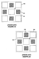
- FIG. 1A shows a conventional honeycomb wall-flow filter 100 having an inlet end 102, an outlet end 104, and an array of interconnecting porous walls 106 extending longitudinally from the inlet end 102 to the outlet end 104.
- the interconnecting porous walls 106 define a grid of inlet channels 108 and outlet channels 110.
- the outlet channels 110 are end-plugged with filler material 112 while inlet channels 108 are not end-plugged.
- the inlet channels 108 are end-plugged with filler material while the outlet channels 110 are not end-plugged.
- FIG. 1B shows a close-up view of the cell structure used in the honeycomb filter.
- the porous walls 106 defining the inlet and outlet channels (or cells) 108, 110 are straight, and the inlet and outlet cells 108, 110 have a square cross-section and equal hydraulic diameter.
- diesel exhaust flows into the honeycomb filter 100 through the unplugged ends of the inlet channels 108 and exits the honeycomb filter through the unplugged ends of the outlet channels 110.
- the diesel exhaust is forced from the inlet channels 108 into the outlet channels 110 through the porous walls 106.
- soot and ash particles accumulate on the porous walls 106, decreasing the effective flow area of the inlet channels 108.
- the decreased effective flow area creates a pressure drop across the honeycomb filter, which leads to a gradual rise in back pressure against the diesel engine. When the pressure drop becomes unacceptable, thermal regeneration is used to remove the soot particles trapped in the honeycomb filter.
- the ash particles which include metal oxide impurities, additives from lubrication oils, sulfates and the like, are not combustible and cannot be removed by thermal regeneration. During thermal regeneration, excessive temperature spikes can occur, which can thermally shock, crack, or even melt, the honeycomb filter.
- the honeycomb filter has sufficient structural strength to withstand thermal regeneration. To avoid the need for frequent thermal regeneration, it is also desirable that the honeycomb filter has a high capacity for storing soot and ash particles.
- the effective flow area of the inlet channels can easily become much smaller than that of the outlet channels, creating a large pressure drop across the honeycomb filter.
- One solution that has been proposed to reducing this pressure drop involves making the hydraulic diameter (or effective cross-sectional flow area) of the inlet channels larger than that of the outlet channels. In this way, as soot and ash particles accumulate on the inlet portion of the porous walls, the effective flow area of the inlet channels will tend to equalize with that of the outlet channels.
- the hydraulic diameter of the inlet cells 108 can be made larger than the outlet cells 110 by reducing the hydraulic diameter of the outlet cells 110.
- Figure 1C shows the honeycomb cell structure of Figure 1B after reducing the hydraulic diameter of the outlet cell 110 such that the outlet cell 110 now has a smaller hydraulic diameter in comparison to the inlet cell 108.
- Another modification that can be made is to increase the hydraulic diameter of the inlet cells 108. This modification has the advantage of increasing the effective surface area available for collecting soot and ash particles in the inlet portion of the honeycomb filter, which ultimately increases the overall storage capacity of the honeycomb filter.
- Figure 1D shows the honeycomb cell structure of Figure 1C after increasing the hydraulic diameter of the inlet cell 108.
- any increase in the hydraulic diameter of the inlet cell 108 would produce a corresponding decrease in the thickness of the wall between the adjacent corners of inlet cells 108 (compare t 2 in Figure 1D with t 1 in Figure 1C ).
- the structural strength of the honeycomb filter decreases, making the honeycomb filter more susceptible to thermal shock and cracking during thermal regeneration.
- JP 1 172 155 S discloses a honeycomb filter comprising an array of interconnecting porous walls which define an array of first channels and second channels, the first channels being bordered on their sides by the second channels and having a larger hydraulic diameter than the second channels, the first channels having a square cross-section.
- US-A-5 256 054 discloses an extrusion die assembly for making a honeycomb filter.
- WO-A2-03/020407 discloses a honeycomb filter comprising the features of the preamble of claim 1.
- the invention relates to a honeycomb filter which comprises an array of interconnecting porous walls that define an array of first channels and second channels.
- the first channels are bordered on their sides by the second channels and have a larger hydraulic diameter than the second channels.
- the first channels have a square cross-section, with corners of the first channels having a shape such that the thickness of the porous walls adjoining corners of the first channels is comparable to the thickness of the porous walls adjoining edges of the first and the second channels.
- the invention in another aspect, relates to a honeycomb filter which comprises an array of interconnecting porous walls that define an array of first channels having a square cross-section and second channels having a square cross-section.
- the first channels are bordered on their edges by the second channels.
- the edges of the first channels are aligned with edges of the bordering second channels.
- the first channels have a larger hydraulic diameter than the second channels.
- the invention in yet another aspect, relates to an extrusion die assembly for making a honeycomb filter which comprises a cell forming die having a central region and a peripheral region.
- the central region comprises an array of discharge slots cut to define an array of first and second pins and an array of first feedholes in communication with the array of discharge slots.
- the peripheral region comprises at least a second feedhole.
- the first pins have a larger cross-sectional area than the second pins.
- the cross-sectional shape of the first pins is selected such that the width of the discharge slots is substantially uniform.
- the extrusion die assembly also includes a skin forming mask mounted coaxially with the cell forming die and radially spaced from the cell forming die so as to define a skin slot that is in selective communication with the at least second feedhole.
- Figure 1A is a perspective view of a prior-art honeycomb wall-flow filter.
- Figure 1B shows a standard honeycomb cell structure having inlet and outlet cells with equal hydraulic diameter.
- Figure 1C shows the honeycomb cell structure of Figure 1B after reducing the hydraulic diameter of the outlet cells.
- Figure 1D shows the honeycomb cell structure of Figure 1C after increasing the hydraulic diameter of the inlet cells.
- Figure 2A is a perspective view of a honeycomb wall-flow filter according to an embodiment of the invention.
- Figure 2B shows a honeycomb cell structure having inlet cells and outlet cells with unequal hydraulic diameters and the inlet cells with filleted corners according to one embodiment of the invention.
- Figure 2C shows a honeycomb cell structure having inlet cells and outlet cells with unequal hydraulic diameters and the inlet cells with beveled corners according to another embodiment of the invention.
- Figure 2D shows a honeycomb cell structure having inlet and outlet cells with unequal hydraulic diameters and aligned edges not according to the invention.
- Figure 2E is a graph of hydraulic diameter of a cell as a function of fillet radius and cell width.
- Figure 3 is a cross-section of an extrusion die assembly according to one embodiment of the invention.
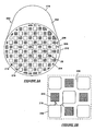
- FIG. 2A shows a honeycomb wall-flow filter 200 according to an embodiment of the invention.
- the honeycomb filter 200 has a columnar body 202 whose cross-sectional shape is defined by a skin (or peripheral wall) 204.
- the profile of the skin 204 is typically circular or elliptical, but the invention is not limited to any particular skin profile.
- the columnar body 202 has an array of interconnecting porous walls 206, which intersect with the skin 204.
- the porous walls 206 define a grid of inlet channels 208 and outlet channels 210 in the columnar body 202.
- the inlet and outlet channels 208, 210 extend longitudinally along the length of the columnar body 202.
- the columnar body 202 is made by extrusion.
- the columnar body 202 is made of a ceramic material, such as cordierite or silicon carbide, but could also be made of other extrudable materials, such as glass, glass-ceramics, plastic, and metal.
- the honeycomb filter 200 has an inlet end 212 for receiving flow, e.g., exhaust gas flow, and an outlet end 214 through which filtered flow can exit the honeycomb filter.
- end portions of the outlet channels 210 are plugged with filler material 216 while the end portions of the inlet channels 208 are not plugged.
- the filler material 216 is made of a ceramic material, such as cordierite or silicon carbide.
- end portions of inlet channels 208 are plugged with filler material while the end portions of the outlet channels 210 are not plugged. Partial cells near the periphery of the skin 204 are typically plugged with filler material.
- the interconnected porous walls 206 allow flow from the inlet channels 208 into the outlet channels 210.
- the porosity of the porous walls 206 can be variable. In general, the porosity should be such that the structural integrity of the honeycomb filter is not compromised.
- the porous walls 206 may incorporate pores having mean diameters in the range of 1 to 60 ⁇ m, more preferably in a range from 10 to 50 ⁇ m.
- FIG. 2B shows a close-up view of the cell structure of the honeycomb filter 200.
- Each inlet cell 208 is bordered by outlet cells 210 and vice versa.
- the inlet cells 208 are made to have a larger hydraulic diameter than the outlet cells 210.
- the outlet cells 210 have a square geometry.
- the inlet cells 208 also have a square geometry, but the corners of the square include fillets 218.
- One purpose of the fillets 218 is to make the thickness (t 3 ) between the adjacent corners of the inlet cells 208 comparable to the thickness (t 4 ) between the inlet cells 208 and the outlet cells 210.
- the thickness t 3 is in a range of about 0.8 to 1.2 times the thickness t 4 .
- the radius of the fillets 218 is selected such that the thickness of the porous walls is substantially uniform around the cells.
- the radius of the fillets 218 may also be selected such that hydraulic diameter of the inlet cells 208 is maximized for a selected cell density and closed frontal area.
- Table 1 below shows examples of cell structures having a cell density of 200 cells/in 2 (about 31 cells/cm 2 ) and a closed frontal area of 47%.
- Cell structures A and B are specific examples of the inventive cell structure shown in Figure 2B .
- Cell structures C and D are specific examples of the prior-art cell structure shown in Figure 1C .
- the hydraulic diameters of the inlet cells of the inventive cell structures A and B are larger than the hydraulic diameters of the inlet cells of the prior-art cell structures C and D, respectively.
- the larger hydraulic diameters of the cell structures A and B are achieved while maintaining the same cell density and closed frontal area as that of the prior-art cell structures C and D.
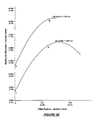
- Figure 2E shows how hydraulic diameter varies as a function of fillet radius for a given cell width.
- the position of the cell structures A, B, C, and D are indicated on the graph.
- the graph shows that hydraulic diameter has a non-linear relationship with fillet radius.
- the inlet cells can be made to have the fillet radius corresponding to the maximum hydraulic diameter achievable for a selected cell width.
- the present invention is not limited to inclusion of fillets 218 at the corners of the inlet cells 208.
- the corners of the inlet cells 208 can also be beveled.
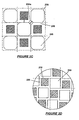
- Figure 2C shows a cell structure where the corners of the inlet cells 208 include bevels 220.
- the inlet cells 208 have also been enlarged such that the edges of (diagonally) adjacent inlet cells 208 are substantially aligned. This increases the overall storage capacity of the honeycomb filter while allowing good flow rates through the honeycomb filter to be maintained.
- the bevels 220 (or fillets if used instead of bevels) enable uniformly thick porous walls 206 to be provided around the cells.
- porous walls 206 are not straight. This leads to an increase in the thermal shock resistance of the honeycomb structure.
- portions of the porous walls e.g., porous wall 206a, are common to only the inlet cells 208. These porous wall portions that are common to only the inlet cells 208 could facilitate transfer of heat from one inlet cell to another during thermal regeneration.
- the fillets and bevels can be used to achieve a substantially uniform porous wall thickness throughout the honeycomb filter while maintaining a desired closed frontal area, cell density, and ratio of hydraulic diameter of inlet cell to outlet cell.
- the ratio of hydraulic diameter of inlet cell to outlet cell is in a range from 1.1 to 2.0, preferably 1.3 to 2.0, more preferably 1.7 to 2.0.
- the thickness of the interconnecting porous walls can vary upwards from the minimum dimension of about 0.002 in. (0.05 mm) providing structural integrity, but is generally less than about 0.060 in (1.5 mm) to minimize filter volume.
- Figure 2D shows a cell structure not according to the present invention where the edges of the inlet cells 208 are aligned with edges of the outlet cells 210 and the thickness of the porous walls 206 is uniform throughout the honeycomb filter without the use of a bevel or fillet at the corners of the inlet cells 208.
- a fillet or bevel to the corners of the inlet cells 208 can further improve the structural strength of the honeycomb filter.
- the porous walls 206 in this embodiment are even less straight than the porous walls in the embodiments previously described, leading to further improvement in thermal shock resistance.
- FIG. 3 shows a vertical cross-section of an extrusion die assembly 300.
- the extrusion die assembly 300 includes a cell forming die 302 and a skin forming mask 304.
- the cell forming die 300 is used to form the interconnecting porous walls that define the inlet and outlet cells of the honeycomb filter.
- the cell forming die 302 cooperate with the skin forming mask 304 to define the shape and thickness of the skin of the honeycomb filter.
- the cell forming die 302 has a central region 306.
- An array of discharge slots 308 is cut in the central region 306 to define an array of inlet and outlet pins 310, 312.
- the transverse cross-section of the inlet and outlet pins 310, 312 is square, with each corner of the inlet pins 310 including a fillet or bevel.
- the central region 306 of the cell forming die 302 further includes an array of central feedholes 314, which extend from the inlet face 315 of the die to the array of discharge slots 308.
- the central feedholes 314 supply batch material to the discharge slots 308.
- the size and location of the central feedholes 314 relative to the discharge slots 308 are selected to achieve a desired flow rate through the discharge slots 308.
- a central feedhole 308 may correspond to each or every other discharge slot 308 or may correspond to each or every other intersection of the discharge slots 308.
- the cell forming die 302 also includes a peripheral region 316 formed contiguous with the central region 306.
- the peripheral region 316 provides a mounting surface 318 for the skin forming mask 304 and includes feedholes 318 for feeding batch material to spaces around the cell forming die 302.
- a shim 320 is interposed between the mounting surface 318 and the skin forming mask 304 to define a skin forming reservoir 322 between the peripheral region 316 and the skin forming mask 304.
- the feedholes 318 in the peripheral region 316 supply batch material to the skin forming reservoir 322.
- the skin forming mask 304 is radially spaced from the central region 306 to define a skin slot 324, which is in communication with the skin forming reservoir 322. Batch material is extruded through the skin slot 324 to form the skin of the honeycomb filter.
- the volume of the reservoir 322 can be adjusted to control the rate at which batch material is supplied into the skin slot 324.
- batch material is fed into the feedholes 314, 318 in the cell forming die 302 and extruded through the discharge slots 308 and the skin forming slot 324.
- the volume of the batch material in the skin forming reservoir 322 is dependent on the extent of the radial overhang of the skin forming mask 304 over the skin forming reservoir 322.
- the rate of flow of batch material into the skin forming slot determines the character of the skin, while the rate of flow of batch material into the discharge slots determine the character of the porous walls.
- the extrusion die assembly described above can be manufactured using existing methods for making extrusion dies.
- the cell forming die may be made by machining holes in a lower portion of a block that is made of a machinable material. These holes would serve as feedholes.
- a process such as plunge electrical discharge machining can be used to cut the discharge slots in the upper portion of the block. Pins remain on the upper portion of the block after the slots are cut.
- the pins at the periphery of the block can be shortened or completely removed to provide a mounting surface for the skin forming mask.
- the discharge slots could have any of the geometries described above in conjunction with the cell structure of the honeycomb filter.
Landscapes
- Chemical & Material Sciences (AREA)
- Engineering & Computer Science (AREA)
- Physics & Mathematics (AREA)
- Geometry (AREA)
- Chemical Kinetics & Catalysis (AREA)
- Ceramic Engineering (AREA)
- Mechanical Engineering (AREA)
- Manufacturing & Machinery (AREA)
- General Engineering & Computer Science (AREA)
- Combustion & Propulsion (AREA)
- Materials Engineering (AREA)
- Structural Engineering (AREA)
- Organic Chemistry (AREA)
- Filtering Materials (AREA)
- Press-Shaping Or Shaping Using Conveyers (AREA)
- Filtering Of Dispersed Particles In Gases (AREA)
- Networks Using Active Elements (AREA)
- Piezo-Electric Or Mechanical Vibrators, Or Delay Or Filter Circuits (AREA)
Abstract
Description
- Honeycomb wall-flow filters are used to remove carbonaceous soot from exhaust of diesel engines.
Figure 1A shows a conventional honeycomb wall-flow filter 100 having aninlet end 102, anoutlet end 104, and an array of interconnectingporous walls 106 extending longitudinally from theinlet end 102 to theoutlet end 104. The interconnectingporous walls 106 define a grid ofinlet channels 108 andoutlet channels 110. At theinlet end 102, theoutlet channels 110 are end-plugged withfiller material 112 whileinlet channels 108 are not end-plugged. Although not visible from the figure, at theoutlet end 104, theinlet channels 108 are end-plugged with filler material while theoutlet channels 110 are not end-plugged. Eachinlet channel 108 is bordered on all sides byoutlet channels 110 and vice versa.Figure 1B shows a close-up view of the cell structure used in the honeycomb filter. Theporous walls 106 defining the inlet and outlet channels (or cells) 108, 110 are straight, and the inlet andoutlet cells - Returning to
Figure 1A , diesel exhaust flows into thehoneycomb filter 100 through the unplugged ends of theinlet channels 108 and exits the honeycomb filter through the unplugged ends of theoutlet channels 110. Inside thehoneycomb filter 100, the diesel exhaust is forced from theinlet channels 108 into theoutlet channels 110 through theporous walls 106. As diesel exhaust flows through thehoneycomb filter 100, soot and ash particles accumulate on theporous walls 106, decreasing the effective flow area of theinlet channels 108. The decreased effective flow area creates a pressure drop across the honeycomb filter, which leads to a gradual rise in back pressure against the diesel engine. When the pressure drop becomes unacceptable, thermal regeneration is used to remove the soot particles trapped in the honeycomb filter. The ash particles, which include metal oxide impurities, additives from lubrication oils, sulfates and the like, are not combustible and cannot be removed by thermal regeneration. During thermal regeneration, excessive temperature spikes can occur, which can thermally shock, crack, or even melt, the honeycomb filter. - It is desirable that the honeycomb filter has sufficient structural strength to withstand thermal regeneration. To avoid the need for frequent thermal regeneration, it is also desirable that the honeycomb filter has a high capacity for storing soot and ash particles. For a cell structure in which the inlet and outlet channels have equal hydraulic diameter, the effective flow area of the inlet channels can easily become much smaller than that of the outlet channels, creating a large pressure drop across the honeycomb filter. One solution that has been proposed to reducing this pressure drop involves making the hydraulic diameter (or effective cross-sectional flow area) of the inlet channels larger than that of the outlet channels. In this way, as soot and ash particles accumulate on the inlet portion of the porous walls, the effective flow area of the inlet channels will tend to equalize with that of the outlet channels.
- For the conventional honeycomb cell structure shown in
Figure 1B , the hydraulic diameter of theinlet cells 108 can be made larger than theoutlet cells 110 by reducing the hydraulic diameter of theoutlet cells 110.Figure 1C shows the honeycomb cell structure ofFigure 1B after reducing the hydraulic diameter of theoutlet cell 110 such that theoutlet cell 110 now has a smaller hydraulic diameter in comparison to theinlet cell 108. Another modification that can be made is to increase the hydraulic diameter of theinlet cells 108. This modification has the advantage of increasing the effective surface area available for collecting soot and ash particles in the inlet portion of the honeycomb filter, which ultimately increases the overall storage capacity of the honeycomb filter.Figure 1D shows the honeycomb cell structure ofFigure 1C after increasing the hydraulic diameter of theinlet cell 108. Without changing the cell density of the honeycomb filter, any increase in the hydraulic diameter of theinlet cell 108 would produce a corresponding decrease in the thickness of the wall between the adjacent corners of inlet cells 108 (compare t2 inFigure 1D with t1 inFigure 1C ). As the wall between the corners of the inlet cells become thinner, the structural strength of the honeycomb filter decreases, making the honeycomb filter more susceptible to thermal shock and cracking during thermal regeneration. -
JP 1 172 155 S -
US-A-5 256 054 discloses an extrusion die assembly for making a honeycomb filter. -
WO-A2-03/020407 - From the foregoing, there is desired a method of improving the storage capacity of the honeycomb filter while maintaining good flow rates through the honeycomb filter without significantly reducing the structural strength of the honeycomb filter.
- In one aspect, the invention relates to a honeycomb filter which comprises an array of interconnecting porous walls that define an array of first channels and second channels. The first channels are bordered on their sides by the second channels and have a larger hydraulic diameter than the second channels. The first channels have a square cross-section, with corners of the first channels having a shape such that the thickness of the porous walls adjoining corners of the first channels is comparable to the thickness of the porous walls adjoining edges of the first and the second channels.
- In another aspect, the invention relates to a honeycomb filter which comprises an array of interconnecting porous walls that define an array of first channels having a square cross-section and second channels having a square cross-section. The first channels are bordered on their edges by the second channels. The edges of the first channels are aligned with edges of the bordering second channels. The first channels have a larger hydraulic diameter than the second channels.
- In yet another aspect, the invention relates to an extrusion die assembly for making a honeycomb filter which comprises a cell forming die having a central region and a peripheral region. The central region comprises an array of discharge slots cut to define an array of first and second pins and an array of first feedholes in communication with the array of discharge slots. The peripheral region comprises at least a second feedhole. The first pins have a larger cross-sectional area than the second pins. The cross-sectional shape of the first pins is selected such that the width of the discharge slots is substantially uniform. The extrusion die assembly also includes a skin forming mask mounted coaxially with the cell forming die and radially spaced from the cell forming die so as to define a skin slot that is in selective communication with the at least second feedhole.
- Other features and advantages of the invention will be apparent from the following description and the appended claims.
-
Figure 1A is a perspective view of a prior-art honeycomb wall-flow filter. -
Figure 1B shows a standard honeycomb cell structure having inlet and outlet cells with equal hydraulic diameter. -
Figure 1C shows the honeycomb cell structure ofFigure 1B after reducing the hydraulic diameter of the outlet cells. -
Figure 1D shows the honeycomb cell structure ofFigure 1C after increasing the hydraulic diameter of the inlet cells. -
Figure 2A is a perspective view of a honeycomb wall-flow filter according to an embodiment of the invention. -
Figure 2B shows a honeycomb cell structure having inlet cells and outlet cells with unequal hydraulic diameters and the inlet cells with filleted corners according to one embodiment of the invention. -
Figure 2C shows a honeycomb cell structure having inlet cells and outlet cells with unequal hydraulic diameters and the inlet cells with beveled corners according to another embodiment of the invention. -
Figure 2D shows a honeycomb cell structure having inlet and outlet cells with unequal hydraulic diameters and aligned edges not according to the invention. -
Figure 2E is a graph of hydraulic diameter of a cell as a function of fillet radius and cell width. -
Figure 3 is a cross-section of an extrusion die assembly according to one embodiment of the invention. - The invention will now be described in detail with reference to a few preferred embodiments, as illustrated in the accompanying drawings. In the following description, numerous specific details are set forth in order to provide a thorough understanding of the invention. It will be apparent, however, to one skilled in the art that the invention may be practiced without some or all of these specific details. In other instances, well-known features and/or process steps have not been described in detail in order to not unnecessarily obscure the invention. The features and advantages of the invention may be better understood with reference to the drawings and discussions that follow.
- For illustration purposes,
Figure 2A shows a honeycomb wall-flow filter 200 according to an embodiment of the invention. Thehoneycomb filter 200 has acolumnar body 202 whose cross-sectional shape is defined by a skin (or peripheral wall) 204. The profile of theskin 204 is typically circular or elliptical, but the invention is not limited to any particular skin profile. Thecolumnar body 202 has an array of interconnectingporous walls 206, which intersect with theskin 204. Theporous walls 206 define a grid ofinlet channels 208 andoutlet channels 210 in thecolumnar body 202. The inlet andoutlet channels columnar body 202. Typically, thecolumnar body 202 is made by extrusion. Typically, thecolumnar body 202 is made of a ceramic material, such as cordierite or silicon carbide, but could also be made of other extrudable materials, such as glass, glass-ceramics, plastic, and metal. - The
honeycomb filter 200 has aninlet end 212 for receiving flow, e.g., exhaust gas flow, and anoutlet end 214 through which filtered flow can exit the honeycomb filter. At theinlet end 212, end portions of theoutlet channels 210 are plugged withfiller material 216 while the end portions of theinlet channels 208 are not plugged. Typically, thefiller material 216 is made of a ceramic material, such as cordierite or silicon carbide. Although not visible from the figure, at theoutlet end 214, end portions ofinlet channels 208 are plugged with filler material while the end portions of theoutlet channels 210 are not plugged. Partial cells near the periphery of theskin 204 are typically plugged with filler material. Inside thehoneycomb filter 200, the interconnectedporous walls 206 allow flow from theinlet channels 208 into theoutlet channels 210. The porosity of theporous walls 206 can be variable. In general, the porosity should be such that the structural integrity of the honeycomb filter is not compromised. For diesel filtration, theporous walls 206 may incorporate pores having mean diameters in the range of 1 to 60 µm, more preferably in a range from 10 to 50 µm. -
Figure 2B shows a close-up view of the cell structure of thehoneycomb filter 200. Eachinlet cell 208 is bordered byoutlet cells 210 and vice versa. To maintain good flow rates when thehoneycomb filter 200 is in use, theinlet cells 208 are made to have a larger hydraulic diameter than theoutlet cells 210. In the illustration, theoutlet cells 210 have a square geometry. In the illustration, theinlet cells 208 also have a square geometry, but the corners of the square includefillets 218. One purpose of thefillets 218 is to make the thickness (t3) between the adjacent corners of theinlet cells 208 comparable to the thickness (t4) between theinlet cells 208 and theoutlet cells 210. The thickness t3 is in a range of about 0.8 to 1.2 times the thickness t4. Preferably, the radius of thefillets 218 is selected such that the thickness of the porous walls is substantially uniform around the cells. The radius of thefillets 218 may also be selected such that hydraulic diameter of theinlet cells 208 is maximized for a selected cell density and closed frontal area. - Table 1 below shows examples of cell structures having a cell density of 200 cells/in2 (about 31 cells/cm2) and a closed frontal area of 47%. Cell structures A and B are specific examples of the inventive cell structure shown in
Figure 2B . Cell structures C and D are specific examples of the prior-art cell structure shown inFigure 1C .Table 1 Cell Structure Inlet cell hydraulic diameter
(mm)Ratio of inlet cell hydraulic diameter to outlet cell hydraulic diameter Inlet cell width
(mm)Outlet cell width
(mm)Fillet radius
(mm)Thickness between adjacent corners of inlet cells
(mm)A 1.68 1.7 1.59 0.98 0.30 0.54 B 1.73 2.0 1.64 0.88 0.30 0.47 C 1.59 1.7 1.59 0.93 None 0.28 D 1.64 2.0 1.64 0.83 None 0.22 
where A is the cross-sectional area of the cell and P is the wetted perimeter of the cell. For a square cell, the hydraulic diameter is the width of the cell. For a square cell with filleted corners, the hydraulic diameter is larger than the width of the cell. - From Table 1 above, the hydraulic diameters of the inlet cells of the inventive cell structures A and B are larger than the hydraulic diameters of the inlet cells of the prior-art cell structures C and D, respectively. The larger hydraulic diameters of the cell structures A and B are achieved while maintaining the same cell density and closed frontal area as that of the prior-art cell structures C and D.
Figure 2E shows how hydraulic diameter varies as a function of fillet radius for a given cell width. The position of the cell structures A, B, C, and D are indicated on the graph. The graph shows that hydraulic diameter has a non-linear relationship with fillet radius. In practice, the inlet cells can be made to have the fillet radius corresponding to the maximum hydraulic diameter achievable for a selected cell width. - Returning to
Figure 2B , the present invention is not limited to inclusion offillets 218 at the corners of theinlet cells 208. The corners of theinlet cells 208 can also be beveled.Figure 2C shows a cell structure where the corners of theinlet cells 208 includebevels 220. In this embodiment, theinlet cells 208 have also been enlarged such that the edges of (diagonally)adjacent inlet cells 208 are substantially aligned. This increases the overall storage capacity of the honeycomb filter while allowing good flow rates through the honeycomb filter to be maintained. The bevels 220 (or fillets if used instead of bevels) enable uniformly thickporous walls 206 to be provided around the cells. For the cell structures shown inFigures 2B and2C , and particularly inFigure 2C , theporous walls 206 are not straight. This leads to an increase in the thermal shock resistance of the honeycomb structure. In the design shown inFigure 2C , portions of the porous walls, e.g.,porous wall 206a, are common to only theinlet cells 208. These porous wall portions that are common to only theinlet cells 208 could facilitate transfer of heat from one inlet cell to another during thermal regeneration. - The fillets and bevels can be used to achieve a substantially uniform porous wall thickness throughout the honeycomb filter while maintaining a desired closed frontal area, cell density, and ratio of hydraulic diameter of inlet cell to outlet cell. The ratio of hydraulic diameter of inlet cell to outlet cell is in a range from 1.1 to 2.0, preferably 1.3 to 2.0, more preferably 1.7 to 2.0. For diesel particulate filtration, a honeycomb having cell density in a range from 10 to 300 cells/in2 (about 1.5 to 46.5 cells/cm2), more typically in a range from 100 to 200 cells/in2 (about 15.5 to 31 cells/cm2), is considered useful to provide sufficient thin wall surface area in a compact structure. The thickness of the interconnecting porous walls can vary upwards from the minimum dimension of about 0.002 in. (0.05 mm) providing structural integrity, but is generally less than about 0.060 in (1.5 mm) to minimize filter volume. A porous wall thickness in a range of about 0.010 to 0.030 in. (about 0.25 to 0.76 mm), preferably in a range from about 0.010 to 0.025 in. (about 0.25 to 0.64 mm), is most often selected at the preferred cell densities.
-
Figure 2D shows a cell structure not according to the present invention where the edges of theinlet cells 208 are aligned with edges of theoutlet cells 210 and the thickness of theporous walls 206 is uniform throughout the honeycomb filter without the use of a bevel or fillet at the corners of theinlet cells 208. However, a fillet or bevel to the corners of theinlet cells 208 can further improve the structural strength of the honeycomb filter. Theporous walls 206 in this embodiment are even less straight than the porous walls in the embodiments previously described, leading to further improvement in thermal shock resistance. - Honeycomb extrusion dies suitable for the manufacture of the honeycomb filter described above would have pin arrays including pins of alternating size. The corners of alternating pins could be rounded or beveled. For illustration purposes,
Figure 3 shows a vertical cross-section of anextrusion die assembly 300. The extrusion dieassembly 300 includes acell forming die 302 and askin forming mask 304. Thecell forming die 300 is used to form the interconnecting porous walls that define the inlet and outlet cells of the honeycomb filter. The cell forming die 302 cooperate with theskin forming mask 304 to define the shape and thickness of the skin of the honeycomb filter. Thecell forming die 302 has acentral region 306. An array ofdischarge slots 308 is cut in thecentral region 306 to define an array of inlet and outlet pins 310, 312. In one embodiment, the transverse cross-section of the inlet and outlet pins 310, 312 is square, with each corner of the inlet pins 310 including a fillet or bevel. - The
central region 306 of the cell forming die 302 further includes an array ofcentral feedholes 314, which extend from theinlet face 315 of the die to the array ofdischarge slots 308. Thecentral feedholes 314 supply batch material to thedischarge slots 308. The size and location of thecentral feedholes 314 relative to thedischarge slots 308 are selected to achieve a desired flow rate through thedischarge slots 308. As an example, acentral feedhole 308 may correspond to each or everyother discharge slot 308 or may correspond to each or every other intersection of thedischarge slots 308. - The cell forming die 302 also includes a
peripheral region 316 formed contiguous with thecentral region 306. Theperipheral region 316 provides a mountingsurface 318 for theskin forming mask 304 and includesfeedholes 318 for feeding batch material to spaces around thecell forming die 302. In one embodiment, ashim 320 is interposed between the mountingsurface 318 and theskin forming mask 304 to define askin forming reservoir 322 between theperipheral region 316 and theskin forming mask 304. Thefeedholes 318 in theperipheral region 316 supply batch material to theskin forming reservoir 322. Theskin forming mask 304 is radially spaced from thecentral region 306 to define askin slot 324, which is in communication with theskin forming reservoir 322. Batch material is extruded through theskin slot 324 to form the skin of the honeycomb filter. The volume of thereservoir 322 can be adjusted to control the rate at which batch material is supplied into theskin slot 324. - In operation, batch material is fed into the
feedholes cell forming die 302 and extruded through thedischarge slots 308 and theskin forming slot 324. The volume of the batch material in theskin forming reservoir 322 is dependent on the extent of the radial overhang of theskin forming mask 304 over theskin forming reservoir 322. The rate of flow of batch material into the skin forming slot determines the character of the skin, while the rate of flow of batch material into the discharge slots determine the character of the porous walls. - The extrusion die assembly described above can be manufactured using existing methods for making extrusion dies. The cell forming die may be made by machining holes in a lower portion of a block that is made of a machinable material. These holes would serve as feedholes. A process such as plunge electrical discharge machining can be used to cut the discharge slots in the upper portion of the block. Pins remain on the upper portion of the block after the slots are cut. The pins at the periphery of the block can be shortened or completely removed to provide a mounting surface for the skin forming mask. The discharge slots could have any of the geometries described above in conjunction with the cell structure of the honeycomb filter.
- While the invention has been described with respect to a limited number of embodiments, those skilled in the art, having benefit of this disclosure, will appreciate that other embodiments can be devised which do not depart from the scope of the invention as disclosed herein. Accordingly, the scope of the invention should be limited only by the attached claims.
Claims (7)
- A honeycomb filter, comprising an array of interconnecting porous walls (206) which define an array of first channels (208) and second channels (210), the first channels (208) being bordered on their sides by the second channels (210) and having a larger hydraulic diameter than the second channels (210), the first channels (208) having a square cross-section, the corners of the first channels (208) having a shape such that the thickness (t3) of the porous walls adjoining corners of the first channels (208) is in a range of 0.8 to 1.2 times the thickness (t4) of the porous walls adjoining edges of the first and the second channels (208, 210), wherein a ratio of the hydraulic diameter of the first channels (208) to the hydraulic diameter of the second channels (210) is in a range from 1.1 to 2.0, characterized in that the shape of the first channels (208) includes a fillet (218) or a bevel (220) at the corners of the first channels (208).
- The honeycomb filter of claim 1, characterized in that edges of diagonally-adjacent first channels (208) are substantially aligned.
- The honeycomb filter of claim 1, characterized in that the second channels (210) have a square cross-section.
- The honeycomb filter of claim 1, characterized in that the ratio of the hydraulic diameter of the first channels (208) to the hydraulic diameter of the second channels (210) is in a range from 1.7 to 2.0.
- An extrusion die assembly for making a honeycomb filter (200) according to any of the claims 1-4, comprising:a cell forming die (302) having a central region (306) and a peripheral region (316), the central region (306) comprising an array of discharge slots (308) cut to define an array of first and second pins (310, 312) and an array of first feedholes (314) in communication with the array of discharge slots, the peripheral region (316) comprising at least a second feedhole (318), the first pins having a larger cross-sectional area than the second pins, a cross sectional shape of the first pins selected such that the width of the discharge slots is substantially uniform, the cross-sectional shape of the first pins including a square having filleted or beveled comers;and a skin forming mask (304) mounted coaxially with the cell forming die and radially spaced from the cell forming die so as to define a skin slot (324) that is in selective communication with the at least second feedhole (318).
- The extrusion die assembly of claim 5, characterized by comprising a skin reservoir (322) defined between the cell forming die (302) and the skin forming mask (304), the skin reservoir (322) being in communication with the at least second feedhole and the skin slot (324).
- The extrusion die assembly of claim 6, characterized in that a volume of the skin reservoir (322) is adjustable to control rate of flow of batch material to the skin slot.
Applications Claiming Priority (2)
| Application Number | Priority Date | Filing Date | Title |
|---|---|---|---|
| US10/671,166 US7247184B2 (en) | 2003-09-25 | 2003-09-25 | Asymmetric honeycomb wall-flow filter having improved structural strength |
| PCT/US2004/030406 WO2005030365A1 (en) | 2003-09-25 | 2004-09-17 | Asymmetric honeycomb wall-flow filter having improved structural strength |
Publications (3)
| Publication Number | Publication Date |
|---|---|
| EP1663447A1 EP1663447A1 (en) | 2006-06-07 |
| EP1663447A4 EP1663447A4 (en) | 2007-06-20 |
| EP1663447B1 true EP1663447B1 (en) | 2010-05-26 |
Family
ID=34376092
Family Applications (1)
| Application Number | Title | Priority Date | Filing Date |
|---|---|---|---|
| EP04784303A Revoked EP1663447B1 (en) | 2003-09-25 | 2004-09-17 | Asymmetric honeycomb wall-flow filter having improved structural strength |
Country Status (7)
| Country | Link |
|---|---|
| US (1) | US7247184B2 (en) |
| EP (1) | EP1663447B1 (en) |
| JP (1) | JP2007519505A (en) |
| CN (2) | CN101386214B (en) |
| AT (1) | ATE468904T1 (en) |
| DE (1) | DE602004027391D1 (en) |
| WO (1) | WO2005030365A1 (en) |
Families Citing this family (70)
| Publication number | Priority date | Publication date | Assignee | Title |
|---|---|---|---|---|
| DE602004011997T2 (en) * | 2003-06-05 | 2009-02-26 | Ibiden Co., Ltd., Ogaki | HONEYCOMB BODY STRUCTURE |
| US7247184B2 (en) | 2003-09-25 | 2007-07-24 | Corning Incorporated | Asymmetric honeycomb wall-flow filter having improved structural strength |
| US7601194B2 (en) * | 2003-09-25 | 2009-10-13 | Corning Incorporated | Asymmetric honeycomb wall-flow filter having improved structural strength |
| US7393377B2 (en) | 2004-02-26 | 2008-07-01 | Ngk Insulators, Ltd. | Honeycomb filter and exhaust gas treatment apparatus |
| CN101263567A (en) * | 2005-07-30 | 2008-09-10 | 康宁股份有限公司 | Cellular honeycomb hybrid capacitors with non-uniform cell geometry |
| DE102005044765A1 (en) * | 2005-09-20 | 2007-03-29 | Robert Bosch Gmbh | Filter element and filter for exhaust aftertreatment |
| DE102006035053A1 (en) * | 2005-09-20 | 2007-03-22 | Robert Bosch Gmbh | Filter element and soot filter with geometrically similar channels |
| DE102005047598A1 (en) * | 2005-10-05 | 2007-04-12 | Robert Bosch Gmbh | Filter element and filter for exhaust aftertreatment |
| US20100133193A1 (en) * | 2007-02-14 | 2010-06-03 | Honeywell International, Inc. | Diesel sulfur filter-nanoadsorber and method of filtering a liquid fuel |
| WO2008117559A1 (en) * | 2007-03-28 | 2008-10-02 | Ngk Insulators, Ltd. | Honeycomb filter |
| US8814974B2 (en) * | 2007-08-24 | 2014-08-26 | Corning Incorporated | Thin-walled porous ceramic wall-flow filter |
| PL2188228T3 (en) * | 2007-08-31 | 2019-05-31 | Corning Inc | Cordierite honeycomb article and method of manufacture |
| KR101457145B1 (en) | 2007-11-08 | 2014-10-31 | 주식회사 칸세라 | Manufacturing method of ceramic formed body having asymmetric channel structure |
| EP2065575B1 (en) * | 2007-11-29 | 2012-08-15 | Corning Incorporated | Wall-flow honeycomb filter having high-storage capacity and low backpressure |
| JP2009243274A (en) * | 2008-03-28 | 2009-10-22 | Mazda Motor Corp | Particulate filter |
| US8187353B2 (en) * | 2009-01-21 | 2012-05-29 | Corning Incorporated | Filtration structures for improved particulate filter performance |
| US8231701B2 (en) * | 2009-01-21 | 2012-07-31 | Corning Incorporated | Particulate filters and methods for regenerating particulate filters |
| US20100301515A1 (en) * | 2009-05-29 | 2010-12-02 | Thomas William Brew | Honeycomb Extrusion Die Apparatus And Methods |
| US20110206896A1 (en) * | 2010-02-25 | 2011-08-25 | Mark Lee Humphrey | Ceramic Honeycomb Body And Process For Manufacture |
| EP2368619B1 (en) * | 2010-03-26 | 2014-06-25 | Imerys | Ceramic honeycomb structures |
| US9856177B2 (en) | 2010-05-28 | 2018-01-02 | Corning Incorporated | Cordierite porous ceramic honeycomb articles |
| US9334191B2 (en) | 2010-05-28 | 2016-05-10 | Corning Incorporated | Methods for forming ceramic honeycomb articles |
| US8999224B2 (en) * | 2010-11-30 | 2015-04-07 | Corning Incorporated | Cordierite porous ceramic honeycomb articles with delayed microcrack evolution |
| US8865084B2 (en) | 2011-11-30 | 2014-10-21 | Corning Incorporated | Pass-through catalytic substrate including porous ceramic beveled corner portions and methods |
| USD744078S1 (en) | 2011-12-07 | 2015-11-24 | Sumitomo Chemical Company, Limited | Particulate filter |
| CN103157387A (en) * | 2011-12-14 | 2013-06-19 | 南京髙谦功能材料科技有限公司 | Palladium or palladium alloy membrane based on wall-flow honeycomb ceramic and preparation method and application thereof |
| DE102012008523A1 (en) | 2012-05-02 | 2013-11-07 | Man Truck & Bus Ag | aftertreatment system |
| WO2013186922A1 (en) | 2012-06-15 | 2013-12-19 | イビデン株式会社 | Honeycomb filter |
| WO2013186923A1 (en) | 2012-06-15 | 2013-12-19 | イビデン株式会社 | Honeycomb filter |
| WO2014054159A1 (en) * | 2012-10-04 | 2014-04-10 | イビデン株式会社 | Honeycomb filter |
| JP5972816B2 (en) * | 2013-03-22 | 2016-08-17 | 日本碍子株式会社 | Honeycomb structure |
| JP6014526B2 (en) * | 2013-03-22 | 2016-10-25 | 日本碍子株式会社 | Honeycomb structure |
| JP6267452B2 (en) * | 2013-07-31 | 2018-01-24 | イビデン株式会社 | Honeycomb filter |
| JP6239305B2 (en) * | 2013-07-31 | 2017-11-29 | イビデン株式会社 | Honeycomb filter |
| JP6239306B2 (en) | 2013-07-31 | 2017-11-29 | イビデン株式会社 | Honeycomb filter |
| JP6239303B2 (en) | 2013-07-31 | 2017-11-29 | イビデン株式会社 | Honeycomb filter |
| JP6239307B2 (en) | 2013-07-31 | 2017-11-29 | イビデン株式会社 | Honeycomb filter |
| JP6239304B2 (en) | 2013-07-31 | 2017-11-29 | イビデン株式会社 | Honeycomb filter |
| US9808794B2 (en) | 2013-09-23 | 2017-11-07 | Corning Incorporated | Honeycomb ceramic substrates, honeycomb extrusion dies, and methods of making honeycomb ceramic substrates |
| GB2520776A (en) | 2013-12-02 | 2015-06-03 | Johnson Matthey Plc | Wall-flow filter comprising catalytic washcoat |
| JP6259327B2 (en) * | 2014-03-13 | 2018-01-10 | 日本碍子株式会社 | Honeycomb structure |
| WO2016158420A1 (en) * | 2015-03-31 | 2016-10-06 | 株式会社小松製作所 | Honeycomb filter |
| GB2542654B (en) | 2015-06-28 | 2019-12-04 | Johnson Matthey Plc | Catalytic wall-flow filter having a membrane |
| JP6594149B2 (en) * | 2015-10-05 | 2019-10-23 | 株式会社キャタラー | Exhaust gas purification device |
| JP6297767B2 (en) * | 2016-03-24 | 2018-03-20 | 株式会社キャタラー | Exhaust gas purification device |
| US9879581B2 (en) * | 2016-03-25 | 2018-01-30 | Caterpillar Inc. | After-treatment system |
| MX2018012815A (en) * | 2016-04-22 | 2019-09-04 | Corning Inc | Rectangular outlet honeycomb structures, particulate filters, extrusion dies, and method of manufacture thereof. |
| GB2558371B (en) | 2016-10-28 | 2021-08-18 | Johnson Matthey Plc | Catalytic wall-flow filter with partial surface coating |
| JP6729356B2 (en) * | 2016-12-27 | 2020-07-22 | 株式会社デンソー | Porous honeycomb filter |
| GB2562160B (en) | 2017-03-20 | 2021-06-23 | Johnson Matthey Plc | Catalytic wall-flow filter with an ammonia slip catalyst |
| GB2562161A (en) | 2017-03-20 | 2018-11-07 | Johnson Matthey Plc | Rear on-wall design SCRF |
| JP2018167200A (en) * | 2017-03-30 | 2018-11-01 | 日本碍子株式会社 | Honeycomb filter |
| JP6862245B2 (en) * | 2017-03-30 | 2021-04-21 | 日本碍子株式会社 | Honeycomb filter |
| CN108278142A (en) * | 2017-12-27 | 2018-07-13 | 山东国瓷功能材料股份有限公司 | A kind of ceramic honey comb plug-hole structure |
| CN108286465A (en) * | 2017-12-27 | 2018-07-17 | 山东国瓷功能材料股份有限公司 | A kind of asymmetric ceramic honey comb wall-flow filter of anti-thermal shock |
| WO2019213569A1 (en) * | 2018-05-04 | 2019-11-07 | Corning Incorporated | High isostatic strength honeycomb structures and extrusion dies therefor |
| EP3844123A1 (en) | 2018-08-31 | 2021-07-07 | Corning Incorporated | Cordierite-indialite-pseudobrookite structured ceramic bodies, batch composition mixtures, and methods of manufacturing ceramic bodies therefrom |
| US11975285B2 (en) | 2018-11-15 | 2024-05-07 | Corning Incorporated | Tilted cell honeycomb body, extrusion die and method of manufacture thereof |
| EP3880342B1 (en) | 2018-11-16 | 2024-06-12 | Corning Incorporated | Cordierite-containing ceramic bodies, batch composition mixtures, and methods of manufacturing cordierite-containing ceramic bodies |
| EP3880340A1 (en) * | 2018-11-16 | 2021-09-22 | Corning Incorporated | Honeycomb bodies having an array of channels with different hydraulic diameters and methods of making the same |
| CN113329806B (en) * | 2018-11-16 | 2022-12-02 | 康宁股份有限公司 | Honeycomb body having an array of through channels with a range of hydraulic diameters |
| CN110107379A (en) * | 2019-06-10 | 2019-08-09 | 常州浩蔚环保科技有限公司 | A kind of asymmetric chamfering structure of ceramic honey comb particle trap |
| CN110253721A (en) * | 2019-07-03 | 2019-09-20 | 南京柯瑞特种陶瓷股份有限公司 | A kind of processing method of asymmetric structure honeycomb ceramics, mold and mold |
| GB201911702D0 (en) | 2019-08-15 | 2019-10-02 | Johnson Matthey Plc | Particulate filters |
| KR20240018530A (en) | 2021-08-27 | 2024-02-13 | 존슨 맛쎄이 퍼블릭 리미티드 컴파니 | Method for forming an inorganic oxide coating on a monolithic article |
| EP4335547A1 (en) | 2022-09-12 | 2024-03-13 | Johnson Matthey Public Limited Company | Method of forming an inorganic oxide coating on a monolith article |
| CN115573793A (en) * | 2022-09-30 | 2023-01-06 | 兰德森排放技术有限公司 | Particulate Filters and Extrusion Dies |
| EP4374952A1 (en) | 2022-11-28 | 2024-05-29 | Johnson Matthey Public Limited Company | Coatings on a monolith article |
| EP4400202A1 (en) | 2023-01-16 | 2024-07-17 | Johnson Matthey Public Limited Company | Coatings on a monolith article |
| EP4624045A1 (en) | 2024-03-28 | 2025-10-01 | Johnson Matthey Public Limited Company | Method of forming an inorganic oxide coating on a monolith article |
Family Cites Families (43)
| Publication number | Priority date | Publication date | Assignee | Title |
|---|---|---|---|---|
| FR789327A (en) | 1934-04-27 | 1935-10-26 | Ig Farbenindustrie Ag | Agents capable of forming foam with air and usable as fire extinguishers |
| GB2064360B (en) * | 1979-12-03 | 1984-05-16 | Gen Motors Corp | Ceramic filters for diesel exhaust particulates and methods for making such filters |
| CA1145270A (en) | 1979-12-03 | 1983-04-26 | Morris Berg | Ceramic filters for diesel exhaust particulates and methods of making |
| US4276071A (en) | 1979-12-03 | 1981-06-30 | General Motors Corporation | Ceramic filters for diesel exhaust particulates |
| US4335023A (en) | 1980-01-24 | 1982-06-15 | Engelhard Corporation | Monolithic catalyst member and support therefor |
| SE433504B (en) | 1980-02-22 | 1984-05-28 | Asea Atom Ab | WAY TO TREAT THE INTERIOR SURFACE OF A RUBBER OF A Zirconia-Based Alloy FOR APPLICATION OF PROTECT LAYERS |
| US4329162A (en) | 1980-07-03 | 1982-05-11 | Corning Glass Works | Diesel particulate trap |
| US4420316A (en) | 1982-02-22 | 1983-12-13 | Corning Glass Works | Filter apparatus and method of making it |
| US4416676A (en) * | 1982-02-22 | 1983-11-22 | Corning Glass Works | Honeycomb filter and method of making it |
| US4417908A (en) * | 1982-02-22 | 1983-11-29 | Corning Glass Works | Honeycomb filter and method of making it |
| US4521532A (en) | 1984-04-23 | 1985-06-04 | General Motors Corporation | Monolithic catalytic converter for improved thermal performance |
| JPS61424A (en) | 1984-06-12 | 1986-01-06 | Nippon Denso Co Ltd | Ceramic filter |
| JPS62234552A (en) * | 1986-04-02 | 1987-10-14 | Mitsubishi Heavy Ind Ltd | Catalytic structure |
| CN86209661U (en) * | 1986-11-27 | 1987-12-12 | 中国有色金属工业总公司昆明贵金属研究所 | Extruding mould for honeycomb catalyst carrier |
| JPH01172155A (en) * | 1987-12-25 | 1989-07-07 | Hashimoto Denki Co Ltd | Method of aligning veneer and device therefor |
| US5256054A (en) | 1990-11-30 | 1993-10-26 | Corning Incorporated | Method and apparatus for forming a uniform skin on a cellular substrate |
| US5219509A (en) * | 1990-11-30 | 1993-06-15 | Corning Incorporated | Method for forming a uniform skin on a cellular substrate |
| US5108685A (en) * | 1990-12-17 | 1992-04-28 | Corning Incorporated | Method and apparatus for forming an article with multi-cellular densities and/or geometries |
| JPH07124428A (en) * | 1993-11-08 | 1995-05-16 | Noritake Co Ltd | Monolith type ceramic filter |
| CN1147210A (en) * | 1994-12-27 | 1997-04-09 | 有限会社米卡子基文化会馆 | Porous ceramic filter, method of mfg. same, extrusion molding die for mfg. same, and extrusion molding machine using same |
| JP3080563B2 (en) * | 1995-08-21 | 2000-08-28 | 日本碍子株式会社 | Manufacturing method of extrusion die for honeycomb structure |
| US5714228A (en) | 1995-12-18 | 1998-02-03 | General Motors Corporation | Ceramic catalytic converter substrate |
| EP0854123B1 (en) | 1996-08-07 | 2006-04-05 | Denso Corporation | Ceramic honeycomb structure and method of production thereof |
| JPH10264125A (en) | 1997-03-28 | 1998-10-06 | Ngk Insulators Ltd | Ceramic honeycomb structure |
| FR2789327B1 (en) | 1999-02-09 | 2001-04-20 | Ecia Equip Composants Ind Auto | POROUS FILTRATION STRUCTURE AND DEPOLLUTION DEVICE COMPRISING SAME |
| DE10037403A1 (en) | 2000-08-01 | 2002-02-14 | Daimler Chrysler Ag | particulate Filter |
| US6464744B2 (en) | 2000-10-03 | 2002-10-15 | Corning Incorporated | Diesel particulate filters |
| US6508852B1 (en) | 2000-10-13 | 2003-01-21 | Corning Incorporated | Honeycomb particulate filters |
| CN2460187Y (en) * | 2000-11-30 | 2001-11-21 | 佟泽林 | Wall through cellular ceramic filter body |
| US6570119B2 (en) | 2001-08-30 | 2003-05-27 | Corning Incorporated | Method of making extrusion die with varying pin size |
| US20030041730A1 (en) | 2001-08-30 | 2003-03-06 | Beall Douglas M. | Honeycomb with varying channel size |
| EP1462230B1 (en) * | 2001-11-05 | 2010-07-14 | Ngk Insulators, Ltd. | Die for molding honeycomb structure and manufacturing method thereof |
| CN2524917Y (en) * | 2001-11-26 | 2002-12-11 | 黄麒荣 | Automobile air filter manufacturing mold |
| JP2004000896A (en) | 2002-03-25 | 2004-01-08 | Ngk Insulators Ltd | Honeycomb filter |
| USD505194S1 (en) | 2002-06-28 | 2005-05-17 | Ibiden Co., Ltd. | Particulate filter for diesel engine |
| USD523543S1 (en) | 2002-06-28 | 2006-06-20 | Ibiden Co., Ltd. | Particulate filter for diesel engine |
| CN1322909C (en) * | 2002-09-13 | 2007-06-27 | 揖斐电株式会社 | honeycomb structure |
| WO2004024295A1 (en) * | 2002-09-13 | 2004-03-25 | Ibiden Co., Ltd. | Honeycomb structure |
| WO2004073969A2 (en) * | 2003-02-18 | 2004-09-02 | Corning Incorporated | Ceramic honeycomb body and process for manufacture |
| US7247184B2 (en) | 2003-09-25 | 2007-07-24 | Corning Incorporated | Asymmetric honeycomb wall-flow filter having improved structural strength |
| US7601194B2 (en) | 2003-09-25 | 2009-10-13 | Corning Incorporated | Asymmetric honeycomb wall-flow filter having improved structural strength |
| US7393377B2 (en) | 2004-02-26 | 2008-07-01 | Ngk Insulators, Ltd. | Honeycomb filter and exhaust gas treatment apparatus |
| US20050274097A1 (en) | 2004-06-14 | 2005-12-15 | Beall Douglas M | Diesel particulate filter with filleted corners |
-
2003
- 2003-09-25 US US10/671,166 patent/US7247184B2/en not_active Expired - Lifetime
-
2004
- 2004-09-17 DE DE602004027391T patent/DE602004027391D1/en not_active Expired - Lifetime
- 2004-09-17 AT AT04784303T patent/ATE468904T1/en not_active IP Right Cessation
- 2004-09-17 CN CN2008101259215A patent/CN101386214B/en not_active Expired - Lifetime
- 2004-09-17 JP JP2006528065A patent/JP2007519505A/en active Pending
- 2004-09-17 CN CNB2004800275973A patent/CN100546695C/en not_active Expired - Lifetime
- 2004-09-17 EP EP04784303A patent/EP1663447B1/en not_active Revoked
- 2004-09-17 WO PCT/US2004/030406 patent/WO2005030365A1/en not_active Ceased
Also Published As
| Publication number | Publication date |
|---|---|
| EP1663447A4 (en) | 2007-06-20 |
| US20050066639A1 (en) | 2005-03-31 |
| JP2007519505A (en) | 2007-07-19 |
| DE602004027391D1 (en) | 2010-07-08 |
| CN1856349A (en) | 2006-11-01 |
| CN101386214A (en) | 2009-03-18 |
| CN101386214B (en) | 2012-03-21 |
| ATE468904T1 (en) | 2010-06-15 |
| WO2005030365A1 (en) | 2005-04-07 |
| US7247184B2 (en) | 2007-07-24 |
| CN100546695C (en) | 2009-10-07 |
| EP1663447A1 (en) | 2006-06-07 |
Similar Documents
| Publication | Publication Date | Title |
|---|---|---|
| EP1663447B1 (en) | Asymmetric honeycomb wall-flow filter having improved structural strength | |
| US7601194B2 (en) | Asymmetric honeycomb wall-flow filter having improved structural strength | |
| US6843822B2 (en) | Filter with varying cell channels | |
| US5731562A (en) | Method of making a ceramic catalytic converter open cell substrate with rounded corners | |
| US7807250B2 (en) | Wall-flow honeycomb filter with hexagonal channel symmetry | |
| EP1594687B1 (en) | Ceramic honeycomb body and process for manufacture | |
| EP2241362A1 (en) | Partially seal-less dpf | |
| US20050274097A1 (en) | Diesel particulate filter with filleted corners | |
| EP3576862B1 (en) | Pattern-plugged honeycomb bodies | |
| EP2010465A1 (en) | Crack-resistant ceramic honeycomb structures | |
| EP3414067B1 (en) | Extrusion components for honeycomb bodies | |
| EP3445472A2 (en) | Rectangular outlet honeycomb structures, particulate filters, extrusion dies, and method of manufacture thereof | |
| EP3727773B1 (en) | Extrusion die | |
| CN112368465B (en) | High-balanced-strength honeycomb structure and extrusion die head for same |
Legal Events
| Date | Code | Title | Description |
|---|---|---|---|
| PUAI | Public reference made under article 153(3) epc to a published international application that has entered the european phase |
Free format text: ORIGINAL CODE: 0009012 |
|
| 17P | Request for examination filed |
Effective date: 20060309 |
|
| AK | Designated contracting states |
Kind code of ref document: A1 Designated state(s): AT BE BG CH CY CZ DE DK EE ES FI FR GB GR HU IE IT LI LU MC NL PL PT RO SE SI SK TR |
|
| DAX | Request for extension of the european patent (deleted) | ||
| A4 | Supplementary search report drawn up and despatched |
Effective date: 20070518 |
|
| RIC1 | Information provided on ipc code assigned before grant |
Ipc: B01D 46/00 20060101AFI20050411BHEP Ipc: B32B 3/12 20060101ALI20070511BHEP Ipc: B01D 46/24 20060101ALI20070511BHEP |
|
| 17Q | First examination report despatched |
Effective date: 20071217 |
|
| GRAP | Despatch of communication of intention to grant a patent |
Free format text: ORIGINAL CODE: EPIDOSNIGR1 |
|
| GRAS | Grant fee paid |
Free format text: ORIGINAL CODE: EPIDOSNIGR3 |
|
| GRAA | (expected) grant |
Free format text: ORIGINAL CODE: 0009210 |
|
| AK | Designated contracting states |
Kind code of ref document: B1 Designated state(s): AT BE BG CH CY CZ DE DK EE ES FI FR GB GR HU IE IT LI LU MC NL PL PT RO SE SI SK TR |
|
| REG | Reference to a national code |
Ref country code: GB Ref legal event code: FG4D |
|
| REG | Reference to a national code |
Ref country code: CH Ref legal event code: EP |
|
| REG | Reference to a national code |
Ref country code: IE Ref legal event code: FG4D |
|
| REF | Corresponds to: |
Ref document number: 602004027391 Country of ref document: DE Date of ref document: 20100708 Kind code of ref document: P |
|
| REG | Reference to a national code |
Ref country code: NL Ref legal event code: VDEP Effective date: 20100526 |
|
| PG25 | Lapsed in a contracting state [announced via postgrant information from national office to epo] |
Ref country code: SE Free format text: LAPSE BECAUSE OF FAILURE TO SUBMIT A TRANSLATION OF THE DESCRIPTION OR TO PAY THE FEE WITHIN THE PRESCRIBED TIME-LIMIT Effective date: 20100526 |
|
| PG25 | Lapsed in a contracting state [announced via postgrant information from national office to epo] |
Ref country code: SI Free format text: LAPSE BECAUSE OF FAILURE TO SUBMIT A TRANSLATION OF THE DESCRIPTION OR TO PAY THE FEE WITHIN THE PRESCRIBED TIME-LIMIT Effective date: 20100526 Ref country code: AT Free format text: LAPSE BECAUSE OF FAILURE TO SUBMIT A TRANSLATION OF THE DESCRIPTION OR TO PAY THE FEE WITHIN THE PRESCRIBED TIME-LIMIT Effective date: 20100526 Ref country code: FI Free format text: LAPSE BECAUSE OF FAILURE TO SUBMIT A TRANSLATION OF THE DESCRIPTION OR TO PAY THE FEE WITHIN THE PRESCRIBED TIME-LIMIT Effective date: 20100526 |
|
| PG25 | Lapsed in a contracting state [announced via postgrant information from national office to epo] |
Ref country code: CY Free format text: LAPSE BECAUSE OF FAILURE TO SUBMIT A TRANSLATION OF THE DESCRIPTION OR TO PAY THE FEE WITHIN THE PRESCRIBED TIME-LIMIT Effective date: 20100526 Ref country code: GR Free format text: LAPSE BECAUSE OF FAILURE TO SUBMIT A TRANSLATION OF THE DESCRIPTION OR TO PAY THE FEE WITHIN THE PRESCRIBED TIME-LIMIT Effective date: 20100827 Ref country code: PL Free format text: LAPSE BECAUSE OF FAILURE TO SUBMIT A TRANSLATION OF THE DESCRIPTION OR TO PAY THE FEE WITHIN THE PRESCRIBED TIME-LIMIT Effective date: 20100526 |
|
| PG25 | Lapsed in a contracting state [announced via postgrant information from national office to epo] |
Ref country code: DK Free format text: LAPSE BECAUSE OF FAILURE TO SUBMIT A TRANSLATION OF THE DESCRIPTION OR TO PAY THE FEE WITHIN THE PRESCRIBED TIME-LIMIT Effective date: 20100526 Ref country code: NL Free format text: LAPSE BECAUSE OF FAILURE TO SUBMIT A TRANSLATION OF THE DESCRIPTION OR TO PAY THE FEE WITHIN THE PRESCRIBED TIME-LIMIT Effective date: 20100526 Ref country code: PT Free format text: LAPSE BECAUSE OF FAILURE TO SUBMIT A TRANSLATION OF THE DESCRIPTION OR TO PAY THE FEE WITHIN THE PRESCRIBED TIME-LIMIT Effective date: 20100927 Ref country code: EE Free format text: LAPSE BECAUSE OF FAILURE TO SUBMIT A TRANSLATION OF THE DESCRIPTION OR TO PAY THE FEE WITHIN THE PRESCRIBED TIME-LIMIT Effective date: 20100526 |
|
| PG25 | Lapsed in a contracting state [announced via postgrant information from national office to epo] |
Ref country code: SK Free format text: LAPSE BECAUSE OF FAILURE TO SUBMIT A TRANSLATION OF THE DESCRIPTION OR TO PAY THE FEE WITHIN THE PRESCRIBED TIME-LIMIT Effective date: 20100526 Ref country code: RO Free format text: LAPSE BECAUSE OF FAILURE TO SUBMIT A TRANSLATION OF THE DESCRIPTION OR TO PAY THE FEE WITHIN THE PRESCRIBED TIME-LIMIT Effective date: 20100526 Ref country code: CZ Free format text: LAPSE BECAUSE OF FAILURE TO SUBMIT A TRANSLATION OF THE DESCRIPTION OR TO PAY THE FEE WITHIN THE PRESCRIBED TIME-LIMIT Effective date: 20100526 Ref country code: BE Free format text: LAPSE BECAUSE OF FAILURE TO SUBMIT A TRANSLATION OF THE DESCRIPTION OR TO PAY THE FEE WITHIN THE PRESCRIBED TIME-LIMIT Effective date: 20100526 |
|
| PLBI | Opposition filed |
Free format text: ORIGINAL CODE: 0009260 |
|
| PLAX | Notice of opposition and request to file observation + time limit sent |
Free format text: ORIGINAL CODE: EPIDOSNOBS2 |
|
| 26 | Opposition filed |
Opponent name: YOUNG THOUGHT LIMITED Effective date: 20110225 |
|
| PG25 | Lapsed in a contracting state [announced via postgrant information from national office to epo] |
Ref country code: MC Free format text: LAPSE BECAUSE OF NON-PAYMENT OF DUE FEES Effective date: 20100930 |
|
| REG | Reference to a national code |
Ref country code: CH Ref legal event code: PL |
|
| REG | Reference to a national code |
Ref country code: DE Ref legal event code: R026 Ref document number: 602004027391 Country of ref document: DE Effective date: 20110225 |
|
| GBPC | Gb: european patent ceased through non-payment of renewal fee |
Effective date: 20100917 |
|
| PG25 | Lapsed in a contracting state [announced via postgrant information from national office to epo] |
Ref country code: CH Free format text: LAPSE BECAUSE OF NON-PAYMENT OF DUE FEES Effective date: 20100930 Ref country code: LI Free format text: LAPSE BECAUSE OF NON-PAYMENT OF DUE FEES Effective date: 20100930 Ref country code: IE Free format text: LAPSE BECAUSE OF NON-PAYMENT OF DUE FEES Effective date: 20100917 |
|
| PLAF | Information modified related to communication of a notice of opposition and request to file observations + time limit |
Free format text: ORIGINAL CODE: EPIDOSCOBS2 |
|
| PG25 | Lapsed in a contracting state [announced via postgrant information from national office to epo] |
Ref country code: GB Free format text: LAPSE BECAUSE OF NON-PAYMENT OF DUE FEES Effective date: 20100917 |
|
| PLBB | Reply of patent proprietor to notice(s) of opposition received |
Free format text: ORIGINAL CODE: EPIDOSNOBS3 |
|
| PG25 | Lapsed in a contracting state [announced via postgrant information from national office to epo] |
Ref country code: BG Free format text: LAPSE BECAUSE OF FAILURE TO SUBMIT A TRANSLATION OF THE DESCRIPTION OR TO PAY THE FEE WITHIN THE PRESCRIBED TIME-LIMIT Effective date: 20100526 Ref country code: HU Free format text: LAPSE BECAUSE OF FAILURE TO SUBMIT A TRANSLATION OF THE DESCRIPTION OR TO PAY THE FEE WITHIN THE PRESCRIBED TIME-LIMIT Effective date: 20101127 Ref country code: LU Free format text: LAPSE BECAUSE OF NON-PAYMENT OF DUE FEES Effective date: 20100917 |
|
| PG25 | Lapsed in a contracting state [announced via postgrant information from national office to epo] |
Ref country code: TR Free format text: LAPSE BECAUSE OF FAILURE TO SUBMIT A TRANSLATION OF THE DESCRIPTION OR TO PAY THE FEE WITHIN THE PRESCRIBED TIME-LIMIT Effective date: 20100526 |
|
| PGFP | Annual fee paid to national office [announced via postgrant information from national office to epo] |
Ref country code: FR Payment date: 20121001 Year of fee payment: 9 Ref country code: IT Payment date: 20120924 Year of fee payment: 9 |
|
| RDAF | Communication despatched that patent is revoked |
Free format text: ORIGINAL CODE: EPIDOSNREV1 |
|
| REG | Reference to a national code |
Ref country code: DE Ref legal event code: R064 Ref document number: 602004027391 Country of ref document: DE Ref country code: DE Ref legal event code: R103 Ref document number: 602004027391 Country of ref document: DE |
|
| PGFP | Annual fee paid to national office [announced via postgrant information from national office to epo] |
Ref country code: DE Payment date: 20120927 Year of fee payment: 9 |
|
| RDAG | Patent revoked |
Free format text: ORIGINAL CODE: 0009271 |
|
| STAA | Information on the status of an ep patent application or granted ep patent |
Free format text: STATUS: PATENT REVOKED |
|
| 27W | Patent revoked |
Effective date: 20130121 |
|
| REG | Reference to a national code |
Ref country code: DE Ref legal event code: R107 Ref document number: 602004027391 Country of ref document: DE Effective date: 20130926 |
|
| PG25 | Lapsed in a contracting state [announced via postgrant information from national office to epo] |
Ref country code: BG Free format text: LAPSE BECAUSE OF FAILURE TO SUBMIT A TRANSLATION OF THE DESCRIPTION OR TO PAY THE FEE WITHIN THE PRESCRIBED TIME-LIMIT Effective date: 20100826 |
|
| PG25 | Lapsed in a contracting state [announced via postgrant information from national office to epo] |
Ref country code: ES Free format text: LAPSE BECAUSE OF FAILURE TO SUBMIT A TRANSLATION OF THE DESCRIPTION OR TO PAY THE FEE WITHIN THE PRESCRIBED TIME-LIMIT Effective date: 20100906 |