US5714228A - Ceramic catalytic converter substrate - Google Patents
Ceramic catalytic converter substrate Download PDFInfo
- Publication number
- US5714228A US5714228A US08/573,778 US57377895A US5714228A US 5714228 A US5714228 A US 5714228A US 57377895 A US57377895 A US 57377895A US 5714228 A US5714228 A US 5714228A
- Authority
- US
- United States
- Prior art keywords
- substrate
- cell walls
- catalytic converter
- walls
- electrode
- Prior art date
- Legal status (The legal status is an assumption and is not a legal conclusion. Google has not performed a legal analysis and makes no representation as to the accuracy of the status listed.)
- Expired - Fee Related
Links
- 239000000758 substrate Substances 0.000 title claims abstract description 54
- 230000003197 catalytic effect Effects 0.000 title claims abstract description 20
- 239000000919 ceramic Substances 0.000 title claims abstract description 18
- 210000002421 cell wall Anatomy 0.000 claims abstract description 31
- 210000004027 cell Anatomy 0.000 claims description 29
- 229910010293 ceramic material Inorganic materials 0.000 claims description 3
- 238000000576 coating method Methods 0.000 claims description 3
- 239000011248 coating agent Substances 0.000 claims 1
- 239000010970 precious metal Substances 0.000 abstract description 4
- 238000001125 extrusion Methods 0.000 description 22
- 238000005520 cutting process Methods 0.000 description 14
- 238000000034 method Methods 0.000 description 10
- 239000000463 material Substances 0.000 description 6
- 239000003054 catalyst Substances 0.000 description 5
- 238000003754 machining Methods 0.000 description 4
- 229910052782 aluminium Inorganic materials 0.000 description 3
- XAGFODPZIPBFFR-UHFFFAOYSA-N aluminium Chemical compound [Al] XAGFODPZIPBFFR-UHFFFAOYSA-N 0.000 description 3
- SBYXRAKIOMOBFF-UHFFFAOYSA-N copper tungsten Chemical compound [Cu].[W] SBYXRAKIOMOBFF-UHFFFAOYSA-N 0.000 description 3
- 239000012530 fluid Substances 0.000 description 3
- 238000011010 flushing procedure Methods 0.000 description 3
- 239000000203 mixture Substances 0.000 description 3
- 239000004593 Epoxy Substances 0.000 description 2
- 229910001315 Tool steel Inorganic materials 0.000 description 2
- 229910052878 cordierite Inorganic materials 0.000 description 2
- JSKIRARMQDRGJZ-UHFFFAOYSA-N dimagnesium dioxido-bis[(1-oxido-3-oxo-2,4,6,8,9-pentaoxa-1,3-disila-5,7-dialuminabicyclo[3.3.1]nonan-7-yl)oxy]silane Chemical compound [Mg++].[Mg++].[O-][Si]([O-])(O[Al]1O[Al]2O[Si](=O)O[Si]([O-])(O1)O2)O[Al]1O[Al]2O[Si](=O)O[Si]([O-])(O1)O2 JSKIRARMQDRGJZ-UHFFFAOYSA-N 0.000 description 2
- 239000003792 electrolyte Substances 0.000 description 2
- 238000000227 grinding Methods 0.000 description 2
- 238000004519 manufacturing process Methods 0.000 description 2
- 238000009761 sinker EDM Methods 0.000 description 2
- 125000006850 spacer group Chemical group 0.000 description 2
- 244000248349 Citrus limon Species 0.000 description 1
- 235000005979 Citrus limon Nutrition 0.000 description 1
- 229910000831 Steel Inorganic materials 0.000 description 1
- 229910001080 W alloy Inorganic materials 0.000 description 1
- 230000015572 biosynthetic process Effects 0.000 description 1
- 239000004568 cement Substances 0.000 description 1
- 238000005336 cracking Methods 0.000 description 1
- 229910003460 diamond Inorganic materials 0.000 description 1
- 239000010432 diamond Substances 0.000 description 1
- 238000009760 electrical discharge machining Methods 0.000 description 1
- 239000007772 electrode material Substances 0.000 description 1
- 238000011049 filling Methods 0.000 description 1
- 238000011068 loading method Methods 0.000 description 1
- 239000000314 lubricant Substances 0.000 description 1
- 238000002844 melting Methods 0.000 description 1
- 230000008018 melting Effects 0.000 description 1
- 229920000609 methyl cellulose Polymers 0.000 description 1
- 239000001923 methylcellulose Substances 0.000 description 1
- 235000010981 methylcellulose Nutrition 0.000 description 1
- 206010028197 multiple epiphyseal dysplasia Diseases 0.000 description 1
- 239000011148 porous material Substances 0.000 description 1
- 230000035939 shock Effects 0.000 description 1
- 239000007787 solid Substances 0.000 description 1
- 239000010959 steel Substances 0.000 description 1
- 235000012222 talc Nutrition 0.000 description 1
- 230000007704 transition Effects 0.000 description 1
- XLYOFNOQVPJJNP-UHFFFAOYSA-N water Substances O XLYOFNOQVPJJNP-UHFFFAOYSA-N 0.000 description 1
Images


Classifications
-
- B—PERFORMING OPERATIONS; TRANSPORTING
- B01—PHYSICAL OR CHEMICAL PROCESSES OR APPARATUS IN GENERAL
- B01D—SEPARATION
- B01D53/00—Separation of gases or vapours; Recovering vapours of volatile solvents from gases; Chemical or biological purification of waste gases, e.g. engine exhaust gases, smoke, fumes, flue gases, aerosols
- B01D53/34—Chemical or biological purification of waste gases
- B01D53/92—Chemical or biological purification of waste gases of engine exhaust gases
- B01D53/94—Chemical or biological purification of waste gases of engine exhaust gases by catalytic processes
- B01D53/9445—Simultaneously removing carbon monoxide, hydrocarbons or nitrogen oxides making use of three-way catalysts [TWC] or four-way-catalysts [FWC]
- B01D53/9454—Simultaneously removing carbon monoxide, hydrocarbons or nitrogen oxides making use of three-way catalysts [TWC] or four-way-catalysts [FWC] characterised by a specific device
-
- B—PERFORMING OPERATIONS; TRANSPORTING
- B01—PHYSICAL OR CHEMICAL PROCESSES OR APPARATUS IN GENERAL
- B01D—SEPARATION
- B01D53/00—Separation of gases or vapours; Recovering vapours of volatile solvents from gases; Chemical or biological purification of waste gases, e.g. engine exhaust gases, smoke, fumes, flue gases, aerosols
- B01D53/34—Chemical or biological purification of waste gases
- B01D53/74—General processes for purification of waste gases; Apparatus or devices specially adapted therefor
- B01D53/86—Catalytic processes
- B01D53/88—Handling or mounting catalysts
- B01D53/885—Devices in general for catalytic purification of waste gases
-
- B—PERFORMING OPERATIONS; TRANSPORTING
- B01—PHYSICAL OR CHEMICAL PROCESSES OR APPARATUS IN GENERAL
- B01J—CHEMICAL OR PHYSICAL PROCESSES, e.g. CATALYSIS OR COLLOID CHEMISTRY; THEIR RELEVANT APPARATUS
- B01J35/00—Catalysts, in general, characterised by their form or physical properties
- B01J35/50—Catalysts, in general, characterised by their form or physical properties characterised by their shape or configuration
- B01J35/56—Foraminous structures having flow-through passages or channels, e.g. grids or three-dimensional monoliths
-
- B—PERFORMING OPERATIONS; TRANSPORTING
- B01—PHYSICAL OR CHEMICAL PROCESSES OR APPARATUS IN GENERAL
- B01J—CHEMICAL OR PHYSICAL PROCESSES, e.g. CATALYSIS OR COLLOID CHEMISTRY; THEIR RELEVANT APPARATUS
- B01J37/00—Processes, in general, for preparing catalysts; Processes, in general, for activation of catalysts
- B01J37/0009—Use of binding agents; Moulding; Pressing; Powdering; Granulating; Addition of materials ameliorating the mechanical properties of the product catalyst
-
- B—PERFORMING OPERATIONS; TRANSPORTING
- B28—WORKING CEMENT, CLAY, OR STONE
- B28B—SHAPING CLAY OR OTHER CERAMIC COMPOSITIONS; SHAPING SLAG; SHAPING MIXTURES CONTAINING CEMENTITIOUS MATERIAL, e.g. PLASTER
- B28B3/00—Producing shaped articles from the material by using presses; Presses specially adapted therefor
- B28B3/20—Producing shaped articles from the material by using presses; Presses specially adapted therefor wherein the material is extruded
- B28B3/26—Extrusion dies
- B28B3/269—For multi-channeled structures, e.g. honeycomb structures
-
- F—MECHANICAL ENGINEERING; LIGHTING; HEATING; WEAPONS; BLASTING
- F01—MACHINES OR ENGINES IN GENERAL; ENGINE PLANTS IN GENERAL; STEAM ENGINES
- F01N—GAS-FLOW SILENCERS OR EXHAUST APPARATUS FOR MACHINES OR ENGINES IN GENERAL; GAS-FLOW SILENCERS OR EXHAUST APPARATUS FOR INTERNAL COMBUSTION ENGINES
- F01N3/00—Exhaust or silencing apparatus having means for purifying, rendering innocuous, or otherwise treating exhaust
- F01N3/08—Exhaust or silencing apparatus having means for purifying, rendering innocuous, or otherwise treating exhaust for rendering innocuous
- F01N3/10—Exhaust or silencing apparatus having means for purifying, rendering innocuous, or otherwise treating exhaust for rendering innocuous by thermal or catalytic conversion of noxious components of exhaust
- F01N3/24—Exhaust or silencing apparatus having means for purifying, rendering innocuous, or otherwise treating exhaust for rendering innocuous by thermal or catalytic conversion of noxious components of exhaust characterised by constructional aspects of converting apparatus
- F01N3/28—Construction of catalytic reactors
- F01N3/2803—Construction of catalytic reactors characterised by structure, by material or by manufacturing of catalyst support
- F01N3/2825—Ceramics
- F01N3/2828—Ceramic multi-channel monoliths, e.g. honeycombs
-
- Y—GENERAL TAGGING OF NEW TECHNOLOGICAL DEVELOPMENTS; GENERAL TAGGING OF CROSS-SECTIONAL TECHNOLOGIES SPANNING OVER SEVERAL SECTIONS OF THE IPC; TECHNICAL SUBJECTS COVERED BY FORMER USPC CROSS-REFERENCE ART COLLECTIONS [XRACs] AND DIGESTS
- Y02—TECHNOLOGIES OR APPLICATIONS FOR MITIGATION OR ADAPTATION AGAINST CLIMATE CHANGE
- Y02T—CLIMATE CHANGE MITIGATION TECHNOLOGIES RELATED TO TRANSPORTATION
- Y02T10/00—Road transport of goods or passengers
- Y02T10/10—Internal combustion engine [ICE] based vehicles
- Y02T10/12—Improving ICE efficiencies
-
- Y—GENERAL TAGGING OF NEW TECHNOLOGICAL DEVELOPMENTS; GENERAL TAGGING OF CROSS-SECTIONAL TECHNOLOGIES SPANNING OVER SEVERAL SECTIONS OF THE IPC; TECHNICAL SUBJECTS COVERED BY FORMER USPC CROSS-REFERENCE ART COLLECTIONS [XRACs] AND DIGESTS
- Y10—TECHNICAL SUBJECTS COVERED BY FORMER USPC
- Y10T—TECHNICAL SUBJECTS COVERED BY FORMER US CLASSIFICATION
- Y10T428/00—Stock material or miscellaneous articles
- Y10T428/24—Structurally defined web or sheet [e.g., overall dimension, etc.]
- Y10T428/24149—Honeycomb-like
- Y10T428/24165—Hexagonally shaped cavities
Definitions
- This invention relates to ceramic catalytic converter substrates and methods of making the same, and more particularly to ceramic substrates having cells with rounded corners and/or a honeycomb or hexagonal design.
- Ceramic catalytic converter substrates are known. Commercial forms of these ceramic catalytic converter substrates have thin walls (0.006-0.008 inches) and square or triangular shaped cells.
- the substrate is formed by extruding a green ceramic mixture through an extrusion die. The extruded plasticized material is then dried and fired to provide a hard solid cordierire catalytic converter substrate. Other ceramic materials with suitable thermal shock resistance and melting temperature can be used.
- a washcoat is applied to the fired substrate and catalyst solutions are impregnated into the washcoat. Thereafter, the substrate is clamped into a suitable catalytic converter housing with an expanding mat compressed between the substrate and the housing.
- Extrusion dies for making catalytic converter substrates are made by forming a grid pattern from the front side of a die plate which meets with a feed pattern formed from the back side of the die plate.
- the grid patterns are formed by grinding wheels, saw blades, or wire electric discharge machining (EDM). All of these processes cut or burn straight slots within the grid portion of the extrusion plates.
- the square or triangular shaped slots are formed by intersecting lines cut by the grinding wheels, saw blades, or wire EDMs.
- the feed patterns are generally made by peck or gun drill or EDM.
- the square or triangular shaped cell walls formed in the substrate may cause additional problems because they are formed by intersecting lines cut in the extrusion die.
- a substantial clamping force is applied to the substrate to compress the expanding mat along lines intersecting the corners of the square or triangular shaped cell walls where they are the weakest. This may cause damage or cracking of the substrate during assembly or in the field.
- the present invention provides advantages over the prior art.
- the invention includes a ceramic catalytic converter substrate having cell walls with rounded corners.
- the cell walls have a honeycomb or hexagonal shape with rounded corners.
- the cell walls may be manufactured in the die plate to produce very thin substrate walls, less than 5/1000 inch. Suitable coatings can be applied to the die walls (by a variety of processes such as CVD) to reduce the substrate cell walls further to 3/1000 inches.
- Preferred embodiments provide increased structural strength of the substrate due to rounded corners of cell walls and/or due to honeycomb or hexagonal shaped walls.
- the rounded corners of the cell walls also substantially increases the strength of the substrate.
- the honeycomb shape of the substrate uniformly dissipates any force applied to the substrate.
- the rounded corner cell walls also allow for a more uniform deposit of washcoat and precious metals thus reducing the amount of precious metals necessary to coat the substrate along with reducing the additional backpressure of the exhaust system caused by the washcoat which normally forms fillets in corners of squared-celled substrates.
- the invention also includes a method of making an electrode to burn the grid configured in the shape substantially mirroring the substrate to be produced; an improved method for making the feedholes which meet with the grid; a method of using such grid and feedhole electrodes to burn an extrusion die, and a method of using such die to extrude a ceramic substrate.
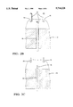
- FIG. 1 is an illustration of an EDM machine used to make grid electrodes and extrusion dies according to the present invention
- FIG. 2A is an enlarged partial view of cutting elements contacting an electrode block according to the present invention.
- FIG. 2B is an enlarged partial view of cutting elements extending through an electrode block according to the present invention.
- FIG. 2C is an enlarged view of an EDM wire, used to cut a grid electrode, extending through a hole in an electrode block according to the present invention
- FIG. 2D illustrates the step and path of the EDM wire cutting a grid electrode according to the present invention
- FIG. 2E is a grid electrode according to the present invention.
- FIG. 3 is an enlarged partial view illustrating a grid electrode cutting an extrusion die according to the present invention
- FIG. 4 is an illustration of the step of extruding a ceramic material through an extrusion die according to the present invention
- FIG. 5 is a sectional view taken along line 5--5 of FIG. 4 illustrating an extrusion die according to the present invention.
- FIGS. 6-9 illustrate a variety of substrate cell designs according to the present invention.
- FIG. 1 illustrates an apparatus 10 and a method of making an electrode 12 according to the present invention.
- the electrode 12 is utilized to burn the extrusion die grid which in turn is utilized to extrude the ceramic catalytic converter substrate once the feedholes which communicate with the grid are also machined into the die.
- An electrode assembly is made to initiate the burning of the grid electrode 12 by taking a plurality of cutting elements 14 and putting them into a bundle formation using a spacer 16 having holes formed therein for carrying cutting elements.
- Conductive epoxy is used to cement the tubes into position.
- a preferred cutting element 14 is made from a carbide material in a tubular shape. The carbide material is preferred because of its low wear rate during burning and it is economical. Tubing is preferred because flushing can be accomplished by sucking fluid through the inner diameter (inside) of the tube.
- the spacer 16 may be made from any of a variety of conducting and dimensionally stable materials such as tool steel and copper-tungsten.
- a block of electrode material 12 is provided which preferably is made from a copper-tungsten alloy. This is because copper-tungsten is very dimensionally stable and exhibits a low wear rate when burning tool steel, and it is easily burned by the carbide tubes.
- the cutting elements 14 and the electrode block 12 are oppositely charged so that material from the block is removed during the process.
- the bundle of cutting elements 14 engage the block 12 surface (FIG. 1 and FIG. 2A) to cut or burn holes 15 through the block (FIG. 2B) at a location that corresponds to the center of the open cell of the substrate to be extruded.
- a flow distributor 32 having holes therein is provided for communicating with the tubular cutting elements 14.
- the flow distributor 32 is made from a 0.5 inch thick aluminum piece (aluminum because its easy to drill) with at least 1 inch additional material outside the drill area to seal upon to make the fluid flow through the machined holes.
- the aluminum flow distributor is drilled with 1/32 inch holes at location corresponding to holes to be burned by the carbide tubes into the electrode 12. So, if 10,000 cells are required in the die, a matching pattern of 10,000 holes would be in the flow distributor 32.
- a flow distributor or plate with fewer and larger diameter holes may also be used.
- a vacuum manifold 26 is used to suck away flush fluid, such as an electrolyte, and cuttings drawn up through the cutting element 14 and flow distributor 32. A detailed description of the system is provided hereafter.
- the electrode block 12 is about 1 inch thick. This allows for about 5/8 inch of usable electrode exposure which can be used to burn many grids over its life.
- an electrical discharge wire 18 is threaded through one hole in the block.
- the EDM wire 18 is worked in a spiral pattern (FIG. 2D) from each hole near the center of the cell to the edge 20 of each cell wall to be formed in the electrode block.
- Each cell 22 (FIG. 2E) is completed by following a continuous path with the wire starting from the hole to the cell wall. Using this continuous path, the cell walls are formed with corners 24 that have a slight radius because of the diameter of the wire used to fabricate the electrode.
- the slight radius is about 0.004 inches or less for a wire having a diameter of about 0.008 inches.
- the radius shown in FIG. 2D is exaggerated for purposes of clarity of illustration.
- a thick border section may be provided on the periphery of the electrode. The border provides the necessary rigidity to guarantee dimensional stability of the electrode when it is utilized to cut the extrusion die. This thick border section of the electrode would be external to the actual die grid being burned.
- the electrode may be formed with cell walls having a square, triangle, or most preferably a honeycomb or hexagonal shape. In each case, the cell walls have rounded corners as described above.
- the finished electrode 12 is now glued with conductive epoxy into a 3/8 inch thick plate with an area machined to accept the grid electrode 12' is operatively connected to a sinker EDM machine and set up to provide a flushing condition wherein electrolyte is forcibly moved between the electrode and the die to be cut in the same manner as with the cutting elements 14 from FIG. 1. This is done by providing suction through a manifold 26 above the grid electrode 12' with passages machined therein so as to provide even flow rates across the entire grid electrode 12'.
- the grid electrode 12' cuts an extrusion grid design in an extrusion block 28.
- the time to burn an entire 4 by 8 inch die is less than 10 hours as compared to many days of machining required by the prior art. Further, the flushing system provides an excellent surface finish in the extrusion die while minimizing electrode wear so that many dies could be burned with a single electrode.
- the present invention provides a reuseable grid electrode 12' that once it is fabricated results in low cost machining time. Unlike the prior art, there is very little chance of scrapping a die in the late hours of machining with the present invention.
- the present invention provides reduction of variation from die to die reducing run-in time. More significantly, the present invention provides the capability of burning very thin slots and producing very thin walls less than 0.005 inches and even down to 0.003 inches with suitable coatings. Further, the present invention can be utilized to produce virtually any cell shape in the electrode or extruded catalytic converter substrate.
- the feedholes 30 in the extrusion die 28 can also be formed economically and accurately by using a bundle of carbide tubes to cut the feed holes similar to the method used to form the starting holes in the grid electrode.
- the setup for burning the holes into the die and burning the holes into the electrode are the same.
- the only difference from the description previous for burning the holes into the electrode is that the flow distributor 32 now has 1/32 inch holes at the center of the holes being burned into the die 28 so the holes will have different spacing to match that pattern.
- the electrode assembly is orbited on a sinker EDM and the feedholes burn out of the die.
- a feedhole may be formed and connected to cells as shown in FIG. 4. Again, carbide tubes are chosen for the same reasons as described previously.
- the electrode assembly can be used to burn feedhole patterns on many dies before it is eroded away.
- rounded bottom slots and holes are to be avoided because this is the transition area for the plastic ceramic mass. This is accomplished by burning a near final depth in one step, facing off the electrode on a wire EDM, and then finishing the burn down to full depth. This eliminates any possible restriction in the area where the plastic ceramic mass must flow laterally from the feedholes to fill the grid.
- an extrusion die for making a 400 CPSI monolith with 0.005 inch walls and hexagonal shaped cells was fabricated using electrodes and extrusion dies as described above. After a grid was burned into the extrusion die by a method described above, feedholes were formed in the extrusion die by burning with carbide tubes as described. Feedholes 30 were provided as shown in FIGS. 4 and 5 communicating with the grid of the extrusion die.
- the die was steel, D2, 0.700 inches thick, hardened and tempered to Rc 52. The holes were 0.046 inch diameter by 0.53 inches deep so as to intersect with the slots which were burned 0.200 inches deep.
- a ceramic mixture 34 containing various clays, calcinated clays, talcs, silicas and aluminas added in ratios to fire out as cordierite were screened through 150 mesh and were plasticized by adding 3% methyl cellulose, 0.75% of a compatible lubricant, and water. The mixture was then kneaded to obtain a desired consistency, de-aired and then forced through the die in mass assembly under 2000 psi pressure applied by a ram 36. The defect-free extrusion was microwave dried and then fired at 1400° C. for 8 hours to produce a 0.005 wall hexagonal cell cordierite monolith for a catalytic converter.
- the monolith was coated with a washcoat which evenly distributed along the cell walls due to the rounded corners and the obtuse angle resulting from hexagonal cells.
- a catalyst was impregnated by pore filling into the washcoat to provide an even catalyst loading throughout the substrate.
- a variety of cell designs such as hexagonal, diamond shape, staggered rectangles and lemon shapes can be formed for thin wall dies as illustrated in FIGS. 6-9 according to this invention.
- the cell design may have variable cell densities. For example, to even out the exhaust volume of flow through the substrate, a higher cell density core with a lower cell density on the periphery cells to force the flow to the periphery of the substrate can be made in accordance with the present invention.
- a catalytic converter substrate according to the present invention includes very thin walls 40. Two walls 40 of the substrate converge to form a rounder corner 42 which provides the above described advantages.
Landscapes
- Chemical & Material Sciences (AREA)
- Engineering & Computer Science (AREA)
- Chemical Kinetics & Catalysis (AREA)
- Environmental & Geological Engineering (AREA)
- Health & Medical Sciences (AREA)
- Ceramic Engineering (AREA)
- Materials Engineering (AREA)
- Biomedical Technology (AREA)
- General Chemical & Material Sciences (AREA)
- Analytical Chemistry (AREA)
- Oil, Petroleum & Natural Gas (AREA)
- Combustion & Propulsion (AREA)
- Mechanical Engineering (AREA)
- Organic Chemistry (AREA)
- Toxicology (AREA)
- Manufacturing & Machinery (AREA)
- General Engineering & Computer Science (AREA)
- Catalysts (AREA)
- Electrical Discharge Machining, Electrochemical Machining, And Combined Machining (AREA)
- Press-Shaping Or Shaping Using Conveyers (AREA)
Abstract
Description
Claims (5)
Priority Applications (2)
| Application Number | Priority Date | Filing Date | Title |
|---|---|---|---|
| US08/573,778 US5714228A (en) | 1995-12-18 | 1995-12-18 | Ceramic catalytic converter substrate |
| US08/781,306 US5731562A (en) | 1995-12-18 | 1997-01-13 | Method of making a ceramic catalytic converter open cell substrate with rounded corners |
Applications Claiming Priority (1)
| Application Number | Priority Date | Filing Date | Title |
|---|---|---|---|
| US08/573,778 US5714228A (en) | 1995-12-18 | 1995-12-18 | Ceramic catalytic converter substrate |
Related Child Applications (1)
| Application Number | Title | Priority Date | Filing Date |
|---|---|---|---|
| US08/781,306 Division US5731562A (en) | 1995-12-18 | 1997-01-13 | Method of making a ceramic catalytic converter open cell substrate with rounded corners |
Publications (1)
| Publication Number | Publication Date |
|---|---|
| US5714228A true US5714228A (en) | 1998-02-03 |
Family
ID=24293363
Family Applications (2)
| Application Number | Title | Priority Date | Filing Date |
|---|---|---|---|
| US08/573,778 Expired - Fee Related US5714228A (en) | 1995-12-18 | 1995-12-18 | Ceramic catalytic converter substrate |
| US08/781,306 Expired - Fee Related US5731562A (en) | 1995-12-18 | 1997-01-13 | Method of making a ceramic catalytic converter open cell substrate with rounded corners |
Family Applications After (1)
| Application Number | Title | Priority Date | Filing Date |
|---|---|---|---|
| US08/781,306 Expired - Fee Related US5731562A (en) | 1995-12-18 | 1997-01-13 | Method of making a ceramic catalytic converter open cell substrate with rounded corners |
Country Status (1)
| Country | Link |
|---|---|
| US (2) | US5714228A (en) |
Cited By (24)
| Publication number | Priority date | Publication date | Assignee | Title |
|---|---|---|---|---|
| EP1068892A2 (en) * | 1999-07-15 | 2001-01-17 | Nissan Motor Co., Ltd. | Exhaust gas purifying catalyst comprising a zeolitic adsorbing layer |
| EP1121981A2 (en) * | 2000-02-01 | 2001-08-08 | Nissan Motor Co., Ltd. | Cold start exhaust gas purifying catalyst |
| US6317960B1 (en) | 1999-12-28 | 2001-11-20 | Corning Incorporated | Extrusion die and method of forming |
| US20020050669A1 (en) * | 1998-09-29 | 2002-05-02 | Takasi Obata | Production process of a hexagonal honeycomb structure |
| US20040161583A1 (en) * | 2003-02-18 | 2004-08-19 | Brew Thomas W. | Ceramic honeycomb body and process for manufacture |
| US20050066639A1 (en) * | 2003-09-25 | 2005-03-31 | Frost Rodney I. | Asymmetric honeycomb wall-flow filter having improved structural strength |
| US20050147791A1 (en) * | 2003-12-29 | 2005-07-07 | Gulati Suresh T. | High-strength thin-walled honeycombs |
| US20050166562A1 (en) * | 2003-09-25 | 2005-08-04 | Beall Douglas M. | Asymmetric honeycomb wall-flow filter having improved structural strength |
| WO2007040348A1 (en) * | 2005-10-04 | 2007-04-12 | Sang Wook Lee | Ceramic catalyst support |
| US20070148406A1 (en) * | 2005-12-27 | 2007-06-28 | Denso Corporation | Hexagonal cell honeycomb structure body |
| US20090031855A1 (en) * | 2007-08-03 | 2009-02-05 | Ramberg Charles E | Porous bodies and methods |
| US20090313829A1 (en) * | 2005-01-14 | 2009-12-24 | Honeywell International Inc. | Microchannel heat exchanger fabricated by wire electro-discharge machining |
| US20100052205A1 (en) * | 2008-08-27 | 2010-03-04 | Thomas William Brew | Method of forming ceramic honeycomb substrates |
| US20110049107A1 (en) * | 2009-08-28 | 2011-03-03 | Mark Lee Humphrey | Electro-Discharge Electrode and Method of Use |
| US20110053757A1 (en) * | 2009-08-28 | 2011-03-03 | Stephen John Caffery | Methods for Making Aluminum Titanate Bodies and Minimizing Shrinkage Variability Thereof |
| US20120175349A1 (en) * | 2010-12-15 | 2012-07-12 | Ngk Insulators, Ltd. | Manufacturing method of electrode for honeycomb structure forming die |
| US8277743B1 (en) | 2009-04-08 | 2012-10-02 | Errcive, Inc. | Substrate fabrication |
| US8359829B1 (en) | 2009-06-25 | 2013-01-29 | Ramberg Charles E | Powertrain controls |
| WO2014114739A1 (en) | 2013-01-25 | 2014-07-31 | Yara International Asa | Honeycomb monolith structure with cells having elongated cross-section |
| US9808794B2 (en) | 2013-09-23 | 2017-11-07 | Corning Incorporated | Honeycomb ceramic substrates, honeycomb extrusion dies, and methods of making honeycomb ceramic substrates |
| US9833932B1 (en) | 2010-06-30 | 2017-12-05 | Charles E. Ramberg | Layered structures |
| US10150076B2 (en) | 2014-07-23 | 2018-12-11 | Yara International Asa | Honeycomb monolith structure |
| US20190240651A1 (en) * | 2018-02-06 | 2019-08-08 | Denso International America, Inc. | Emissions Control Substrate |
| US10598068B2 (en) | 2015-12-21 | 2020-03-24 | Emissol, Llc | Catalytic converters having non-linear flow channels |
Families Citing this family (7)
| Publication number | Priority date | Publication date | Assignee | Title |
|---|---|---|---|---|
| JP2001225312A (en) * | 1999-12-10 | 2001-08-21 | Ngk Insulators Ltd | Method for manufacturing mouth piece |
| GB0209513D0 (en) * | 2002-04-25 | 2002-06-05 | Cambridge Display Tech Ltd | Display devices |
| AT501888B1 (en) * | 2005-06-08 | 2006-12-15 | Fleck Carl M Dr | WAVE FILTER WITH PLANAR ELECTRODES |
| BR112012023703B1 (en) * | 2010-04-01 | 2018-09-25 | Basf Corp | method for preparing a coated monolithic support member, monolithic support member, and use of a monolithic support member |
| JP2012125882A (en) * | 2010-12-15 | 2012-07-05 | Ngk Insulators Ltd | Electrode for mouthpiece for forming honeycomb structure |
| US8865084B2 (en) | 2011-11-30 | 2014-10-21 | Corning Incorporated | Pass-through catalytic substrate including porous ceramic beveled corner portions and methods |
| US10364720B2 (en) * | 2013-09-18 | 2019-07-30 | Advanced Technology Emission Solutions Inc. | Methods for inserting wires into a gaseous emissions treatment unit |
Citations (10)
| Publication number | Priority date | Publication date | Assignee | Title |
|---|---|---|---|---|
| US3853485A (en) * | 1972-12-11 | 1974-12-10 | Corning Glass Works | Core member for catalytic oxidation converter |
| US3903341A (en) * | 1973-09-20 | 1975-09-02 | Universal Oil Prod Co | Ceramic honeycomb structure for accommodating compression and tension forces |
| US4329162A (en) * | 1980-07-03 | 1982-05-11 | Corning Glass Works | Diesel particulate trap |
| US4348360A (en) * | 1979-11-05 | 1982-09-07 | Minnesota Mining And Manufacturing Company | Catalytic converter for ozone removal in aircraft |
| US4448828A (en) * | 1980-07-11 | 1984-05-15 | Ngk Insulators, Ltd. | Ceramic honeycomb structural bodies |
| US4711009A (en) * | 1986-02-18 | 1987-12-08 | W. R. Grace & Co. | Process for making metal substrate catalytic converter cores |
| US4928485A (en) * | 1989-06-06 | 1990-05-29 | W. R. Grace & Co.,-Conn. | Metallic core member for catalytic converter and catalytic converter containing same |
| US4984487A (en) * | 1989-08-24 | 1991-01-15 | General Motors Corporation | Method for manufacturing a die for extruding honeycomb material |
| US5026273A (en) * | 1988-07-15 | 1991-06-25 | W. R. Grace & Co.-Conn. | High temperature combuster |
| US5322537A (en) * | 1992-04-28 | 1994-06-21 | Matsushita Electric Industrial Co., Ltd. | Exhaust gas filter and method for making the same |
Family Cites Families (6)
| Publication number | Priority date | Publication date | Assignee | Title |
|---|---|---|---|---|
| GB2143445B (en) * | 1983-07-16 | 1987-02-11 | Pressabrade Limited | Manufacture of extrusion dies |
| US5066215A (en) * | 1988-08-29 | 1991-11-19 | Corning Incorporated | Extrusion die for forming thin-walled honeycomb structures |
| US5322599A (en) * | 1993-01-19 | 1994-06-21 | Corning Incorporated | Shaped-tube electrolytic machining process |
| US5308568A (en) * | 1993-05-20 | 1994-05-03 | Corning Incorporated | Extrusion die and method |
| US5402692A (en) * | 1993-08-10 | 1995-04-04 | Bennett; Edward D. | Method of making blanking dies and punches having rounded edges |
| US5630951A (en) * | 1995-05-15 | 1997-05-20 | Corning Incorporated | Methods and apparatus for making honeycomb extrusion dies |
-
1995
- 1995-12-18 US US08/573,778 patent/US5714228A/en not_active Expired - Fee Related
-
1997
- 1997-01-13 US US08/781,306 patent/US5731562A/en not_active Expired - Fee Related
Patent Citations (10)
| Publication number | Priority date | Publication date | Assignee | Title |
|---|---|---|---|---|
| US3853485A (en) * | 1972-12-11 | 1974-12-10 | Corning Glass Works | Core member for catalytic oxidation converter |
| US3903341A (en) * | 1973-09-20 | 1975-09-02 | Universal Oil Prod Co | Ceramic honeycomb structure for accommodating compression and tension forces |
| US4348360A (en) * | 1979-11-05 | 1982-09-07 | Minnesota Mining And Manufacturing Company | Catalytic converter for ozone removal in aircraft |
| US4329162A (en) * | 1980-07-03 | 1982-05-11 | Corning Glass Works | Diesel particulate trap |
| US4448828A (en) * | 1980-07-11 | 1984-05-15 | Ngk Insulators, Ltd. | Ceramic honeycomb structural bodies |
| US4711009A (en) * | 1986-02-18 | 1987-12-08 | W. R. Grace & Co. | Process for making metal substrate catalytic converter cores |
| US5026273A (en) * | 1988-07-15 | 1991-06-25 | W. R. Grace & Co.-Conn. | High temperature combuster |
| US4928485A (en) * | 1989-06-06 | 1990-05-29 | W. R. Grace & Co.,-Conn. | Metallic core member for catalytic converter and catalytic converter containing same |
| US4984487A (en) * | 1989-08-24 | 1991-01-15 | General Motors Corporation | Method for manufacturing a die for extruding honeycomb material |
| US5322537A (en) * | 1992-04-28 | 1994-06-21 | Matsushita Electric Industrial Co., Ltd. | Exhaust gas filter and method for making the same |
Cited By (60)
| Publication number | Priority date | Publication date | Assignee | Title |
|---|---|---|---|---|
| BE1014388A3 (en) * | 1998-09-29 | 2003-10-07 | Denso Corp | Method for producing a structure honeycomb hex. |
| DE19935124B4 (en) * | 1998-09-29 | 2010-06-17 | DENSO CORPORATION, Kariya-shi | Production process for a hexagonal honeycomb structure |
| US20020050669A1 (en) * | 1998-09-29 | 2002-05-02 | Takasi Obata | Production process of a hexagonal honeycomb structure |
| EP1068892A2 (en) * | 1999-07-15 | 2001-01-17 | Nissan Motor Co., Ltd. | Exhaust gas purifying catalyst comprising a zeolitic adsorbing layer |
| EP1068892A3 (en) * | 1999-07-15 | 2002-03-06 | Nissan Motor Co., Ltd. | Exhaust gas purifying catalyst comprising a zeolitic adsorbing layer |
| US6444610B1 (en) | 1999-07-15 | 2002-09-03 | Nissan Motor Co., Ltd. | Exhaust gas purifying catalyst |
| US6317960B1 (en) | 1999-12-28 | 2001-11-20 | Corning Incorporated | Extrusion die and method of forming |
| EP1121981A3 (en) * | 2000-02-01 | 2001-11-21 | Nissan Motor Co., Ltd. | Cold start exhaust gas purifying catalyst |
| US6503862B1 (en) | 2000-02-01 | 2003-01-07 | Nissan Motor Co., Ltd. | Exhaust gas purifying catalyst |
| EP1364708A1 (en) * | 2000-02-01 | 2003-11-26 | Nissan Motor Co., Ltd. | Exaust gas purifying catalyst |
| EP1121981A2 (en) * | 2000-02-01 | 2001-08-08 | Nissan Motor Co., Ltd. | Cold start exhaust gas purifying catalyst |
| US20040161583A1 (en) * | 2003-02-18 | 2004-08-19 | Brew Thomas W. | Ceramic honeycomb body and process for manufacture |
| US6803087B2 (en) | 2003-02-18 | 2004-10-12 | Corning Incorporated | Ceramic honeycomb body and process for manufacture |
| US20050066639A1 (en) * | 2003-09-25 | 2005-03-31 | Frost Rodney I. | Asymmetric honeycomb wall-flow filter having improved structural strength |
| US20050166562A1 (en) * | 2003-09-25 | 2005-08-04 | Beall Douglas M. | Asymmetric honeycomb wall-flow filter having improved structural strength |
| US7247184B2 (en) | 2003-09-25 | 2007-07-24 | Corning Incorporated | Asymmetric honeycomb wall-flow filter having improved structural strength |
| US7601194B2 (en) | 2003-09-25 | 2009-10-13 | Corning Incorporated | Asymmetric honeycomb wall-flow filter having improved structural strength |
| US20100009024A1 (en) * | 2003-09-25 | 2010-01-14 | Beall Douglas M | Asymmetric Honeycomb Wall-Flow Filter Having Improved Structural Strength |
| US7279213B2 (en) | 2003-12-29 | 2007-10-09 | Corning Incorporated | High-strength thin-walled honeycombs |
| US20050147791A1 (en) * | 2003-12-29 | 2005-07-07 | Gulati Suresh T. | High-strength thin-walled honeycombs |
| US20090313829A1 (en) * | 2005-01-14 | 2009-12-24 | Honeywell International Inc. | Microchannel heat exchanger fabricated by wire electro-discharge machining |
| US7950149B2 (en) * | 2005-01-14 | 2011-05-31 | Honeywell International, Inc. | Microchannel heat exchanger fabricated by wire electro-discharge machining |
| WO2007040348A1 (en) * | 2005-10-04 | 2007-04-12 | Sang Wook Lee | Ceramic catalyst support |
| US20070148406A1 (en) * | 2005-12-27 | 2007-06-28 | Denso Corporation | Hexagonal cell honeycomb structure body |
| US7504146B2 (en) * | 2005-12-27 | 2009-03-17 | Denso Corporation | Hexagonal cell honeycomb structure body |
| US7981375B2 (en) | 2007-08-03 | 2011-07-19 | Errcive, Inc. | Porous bodies and methods |
| US8361406B2 (en) | 2007-08-03 | 2013-01-29 | Errcive, Inc. | Porous bodies and methods |
| US20100298124A1 (en) * | 2007-08-03 | 2010-11-25 | Errcive, Inc. | Porous Bodies and Methods |
| US8821803B2 (en) | 2007-08-03 | 2014-09-02 | Errcive, Inc. | Porous bodies and methods |
| US8623287B2 (en) | 2007-08-03 | 2014-01-07 | Errcive, Inc. | Porous bodies and methods |
| US20090031855A1 (en) * | 2007-08-03 | 2009-02-05 | Ramberg Charles E | Porous bodies and methods |
| US8092753B2 (en) | 2007-08-03 | 2012-01-10 | Errcive, Inc. | Porous bodies and methods |
| US8097220B2 (en) | 2007-08-03 | 2012-01-17 | Errcive, Inc. | Porous bodies and methods |
| US8551216B2 (en) | 2007-08-03 | 2013-10-08 | Errcive, Inc. | Porous bodies and methods |
| US8221694B2 (en) | 2007-08-03 | 2012-07-17 | Errcive, Inc. | Porous bodies and methods |
| US8361420B2 (en) | 2007-08-03 | 2013-01-29 | Errcive, Inc. | Porous bodies and methods |
| US20100052205A1 (en) * | 2008-08-27 | 2010-03-04 | Thomas William Brew | Method of forming ceramic honeycomb substrates |
| US9511345B1 (en) | 2009-04-08 | 2016-12-06 | Errcive, Inc. | Substrate fabrication |
| US8277743B1 (en) | 2009-04-08 | 2012-10-02 | Errcive, Inc. | Substrate fabrication |
| US8679418B2 (en) | 2009-04-08 | 2014-03-25 | Errcive, Inc. | Substrate fabrication |
| US8359829B1 (en) | 2009-06-25 | 2013-01-29 | Ramberg Charles E | Powertrain controls |
| US20110053757A1 (en) * | 2009-08-28 | 2011-03-03 | Stephen John Caffery | Methods for Making Aluminum Titanate Bodies and Minimizing Shrinkage Variability Thereof |
| US8263895B2 (en) | 2009-08-28 | 2012-09-11 | Corning Incorporated | Electro-discharge electrode and method of use |
| JP2011045993A (en) * | 2009-08-28 | 2011-03-10 | Corning Inc | Discharge electrode and method using the same |
| US20110049107A1 (en) * | 2009-08-28 | 2011-03-03 | Mark Lee Humphrey | Electro-Discharge Electrode and Method of Use |
| US9833932B1 (en) | 2010-06-30 | 2017-12-05 | Charles E. Ramberg | Layered structures |
| US20120175349A1 (en) * | 2010-12-15 | 2012-07-12 | Ngk Insulators, Ltd. | Manufacturing method of electrode for honeycomb structure forming die |
| US9162302B2 (en) * | 2010-12-15 | 2015-10-20 | Ngk Insulators, Ltd. | Manufacturing method of electrode for honeycomb structure forming die |
| CN104936695B (en) * | 2013-01-25 | 2017-11-14 | 亚拉国际有限公司 | Honeycomb monolith structures with the hole with elongate section |
| JP2016511136A (en) * | 2013-01-25 | 2016-04-14 | ヤラ・インターナショナル・アーエスアーYara International ASA | Honeycomb monolith structure with cells having an elongated cross section |
| WO2014114739A1 (en) | 2013-01-25 | 2014-07-31 | Yara International Asa | Honeycomb monolith structure with cells having elongated cross-section |
| CN104936695A (en) * | 2013-01-25 | 2015-09-23 | 亚拉国际有限公司 | Honeycomb monolith structure with cells having elongated cross-section |
| US20150336094A1 (en) * | 2013-01-25 | 2015-11-26 | Yara International Asa | Novel honeycomb monolith structure |
| US10189017B2 (en) * | 2013-01-25 | 2019-01-29 | Yara International Asa | Honeycomb monolith structure |
| US9808794B2 (en) | 2013-09-23 | 2017-11-07 | Corning Incorporated | Honeycomb ceramic substrates, honeycomb extrusion dies, and methods of making honeycomb ceramic substrates |
| US10150076B2 (en) | 2014-07-23 | 2018-12-11 | Yara International Asa | Honeycomb monolith structure |
| US10598068B2 (en) | 2015-12-21 | 2020-03-24 | Emissol, Llc | Catalytic converters having non-linear flow channels |
| US10815856B2 (en) | 2015-12-21 | 2020-10-27 | Mansour Masoudi | Catalytic converters having non-linear flow channels |
| US20190240651A1 (en) * | 2018-02-06 | 2019-08-08 | Denso International America, Inc. | Emissions Control Substrate |
| US10792653B2 (en) * | 2018-02-06 | 2020-10-06 | Denso International America, Inc. | Emissions control substrate |
Also Published As
| Publication number | Publication date |
|---|---|
| US5731562A (en) | 1998-03-24 |
Similar Documents
| Publication | Publication Date | Title |
|---|---|---|
| US5714228A (en) | Ceramic catalytic converter substrate | |
| US7247184B2 (en) | Asymmetric honeycomb wall-flow filter having improved structural strength | |
| US7601194B2 (en) | Asymmetric honeycomb wall-flow filter having improved structural strength | |
| EP1423266B1 (en) | Honeycomb with varying channel size and die for manufacturing | |
| EP0389253B1 (en) | A process for the producing of ceramic honeycomb structure-extruding dies | |
| CA1318485C (en) | Extrusion die for protrusion and/or high cell density ceramic honeycomb structures | |
| EP1864772B1 (en) | Method of manufacturing ferrule for molding honeycomb structure and ferrule for molding honeycomb structure | |
| US6290837B1 (en) | Method for machining slots in molding die | |
| US20080124423A1 (en) | Extrusion die manufacturing method | |
| CA1143337A (en) | Die for extruding a honeycomb structural body and a method for manufacturing the same | |
| US5630951A (en) | Methods and apparatus for making honeycomb extrusion dies | |
| EP0290632B1 (en) | Die and process | |
| EP3788241B1 (en) | High isostatic strength honeycomb structure and extrusion die therefor | |
| JP3745504B2 (en) | Die for extruding honeycomb structure and manufacturing method thereof | |
| WO2020236474A1 (en) | Honeycomb extrusion dies and forming methods | |
| CA1314263C (en) | Dies for extrusion-shaping ceramic honeycomb structural bodies | |
| WO2019232150A1 (en) | Honeycomb extrusion dies and forming methods | |
| US20240190043A1 (en) | Honeycomb extrusion dies and methods of using and making same |
Legal Events
| Date | Code | Title | Description |
|---|---|---|---|
| AS | Assignment |
Owner name: GENERAL MOTORS CORPORATION, MICHIGAN Free format text: ASSIGNMENT OF ASSIGNORS INTEREST;ASSIGNORS:BECKMEYER, RICHARD FREDERICK;GRUBER, SIEGFRIED FRANZ;REEL/FRAME:007883/0806;SIGNING DATES FROM 19960104 TO 19960117 |
|
| FPAY | Fee payment |
Year of fee payment: 4 |
|
| REMI | Maintenance fee reminder mailed | ||
| LAPS | Lapse for failure to pay maintenance fees | ||
| LAPS | Lapse for failure to pay maintenance fees |
Free format text: PATENT EXPIRED FOR FAILURE TO PAY MAINTENANCE FEES (ORIGINAL EVENT CODE: EXP.); ENTITY STATUS OF PATENT OWNER: LARGE ENTITY |
|
| STCH | Information on status: patent discontinuation |
Free format text: PATENT EXPIRED DUE TO NONPAYMENT OF MAINTENANCE FEES UNDER 37 CFR 1.362 |
|
| FP | Lapsed due to failure to pay maintenance fee |
Effective date: 20060203 |