EP3727773B1 - Extrusionsmatrize - Google Patents
Extrusionsmatrize Download PDFInfo
- Publication number
- EP3727773B1 EP3727773B1 EP18859973.2A EP18859973A EP3727773B1 EP 3727773 B1 EP3727773 B1 EP 3727773B1 EP 18859973 A EP18859973 A EP 18859973A EP 3727773 B1 EP3727773 B1 EP 3727773B1
- Authority
- EP
- European Patent Office
- Prior art keywords
- slots
- narrow
- wide
- honeycomb
- slot
- Prior art date
- Legal status (The legal status is an assumption and is not a legal conclusion. Google has not performed a legal analysis and makes no representation as to the accuracy of the status listed.)
- Active
Links
- 238000001125 extrusion Methods 0.000 title claims description 110
- 238000007373 indentation Methods 0.000 claims description 47
- 239000011159 matrix material Substances 0.000 claims description 9
- 239000000203 mixture Substances 0.000 description 25
- 210000004027 cell Anatomy 0.000 description 24
- 238000000034 method Methods 0.000 description 12
- 210000002421 cell wall Anatomy 0.000 description 11
- 239000000919 ceramic Substances 0.000 description 10
- 230000002093 peripheral effect Effects 0.000 description 10
- 239000000463 material Substances 0.000 description 8
- 238000004891 communication Methods 0.000 description 6
- 239000012530 fluid Substances 0.000 description 6
- 238000005520 cutting process Methods 0.000 description 5
- 238000010586 diagram Methods 0.000 description 5
- 238000010304 firing Methods 0.000 description 5
- 239000003054 catalyst Substances 0.000 description 4
- 229910010293 ceramic material Inorganic materials 0.000 description 4
- 239000007789 gas Substances 0.000 description 4
- 239000000758 substrate Substances 0.000 description 4
- XBWAZCLHZCFCGK-UHFFFAOYSA-N 7-chloro-1-methyl-5-phenyl-3,4-dihydro-2h-1,4-benzodiazepin-1-ium;chloride Chemical compound [Cl-].C12=CC(Cl)=CC=C2[NH+](C)CCN=C1C1=CC=CC=C1 XBWAZCLHZCFCGK-UHFFFAOYSA-N 0.000 description 3
- 239000004568 cement Substances 0.000 description 3
- 230000007246 mechanism Effects 0.000 description 3
- 238000011144 upstream manufacturing Methods 0.000 description 3
- 229910000505 Al2TiO5 Inorganic materials 0.000 description 2
- 229910052581 Si3N4 Inorganic materials 0.000 description 2
- 239000012700 ceramic precursor Substances 0.000 description 2
- 238000004140 cleaning Methods 0.000 description 2
- 229910052878 cordierite Inorganic materials 0.000 description 2
- JSKIRARMQDRGJZ-UHFFFAOYSA-N dimagnesium dioxido-bis[(1-oxido-3-oxo-2,4,6,8,9-pentaoxa-1,3-disila-5,7-dialuminabicyclo[3.3.1]nonan-7-yl)oxy]silane Chemical compound [Mg++].[Mg++].[O-][Si]([O-])(O[Al]1O[Al]2O[Si](=O)O[Si]([O-])(O1)O2)O[Al]1O[Al]2O[Si](=O)O[Si]([O-])(O1)O2 JSKIRARMQDRGJZ-UHFFFAOYSA-N 0.000 description 2
- KZHJGOXRZJKJNY-UHFFFAOYSA-N dioxosilane;oxo(oxoalumanyloxy)alumane Chemical compound O=[Si]=O.O=[Si]=O.O=[Al]O[Al]=O.O=[Al]O[Al]=O.O=[Al]O[Al]=O KZHJGOXRZJKJNY-UHFFFAOYSA-N 0.000 description 2
- 238000001035 drying Methods 0.000 description 2
- 230000006872 improvement Effects 0.000 description 2
- 229910052863 mullite Inorganic materials 0.000 description 2
- 230000008569 process Effects 0.000 description 2
- AABBHSMFGKYLKE-SNAWJCMRSA-N propan-2-yl (e)-but-2-enoate Chemical compound C\C=C\C(=O)OC(C)C AABBHSMFGKYLKE-SNAWJCMRSA-N 0.000 description 2
- HBMJWWWQQXIZIP-UHFFFAOYSA-N silicon carbide Chemical compound [Si+]#[C-] HBMJWWWQQXIZIP-UHFFFAOYSA-N 0.000 description 2
- 229910010271 silicon carbide Inorganic materials 0.000 description 2
- HQVNEWCFYHHQES-UHFFFAOYSA-N silicon nitride Chemical compound N12[Si]34N5[Si]62N3[Si]51N64 HQVNEWCFYHHQES-UHFFFAOYSA-N 0.000 description 2
- 230000009471 action Effects 0.000 description 1
- PNEYBMLMFCGWSK-UHFFFAOYSA-N aluminium oxide Inorganic materials [O-2].[O-2].[O-2].[Al+3].[Al+3] PNEYBMLMFCGWSK-UHFFFAOYSA-N 0.000 description 1
- 230000000712 assembly Effects 0.000 description 1
- 238000000429 assembly Methods 0.000 description 1
- QVGXLLKOCUKJST-UHFFFAOYSA-N atomic oxygen Chemical compound [O] QVGXLLKOCUKJST-UHFFFAOYSA-N 0.000 description 1
- 230000015572 biosynthetic process Effects 0.000 description 1
- 238000009924 canning Methods 0.000 description 1
- 230000003197 catalytic effect Effects 0.000 description 1
- 230000001413 cellular effect Effects 0.000 description 1
- 238000002485 combustion reaction Methods 0.000 description 1
- 238000005336 cracking Methods 0.000 description 1
- 230000007547 defect Effects 0.000 description 1
- 238000011161 development Methods 0.000 description 1
- 238000009826 distribution Methods 0.000 description 1
- 238000000227 grinding Methods 0.000 description 1
- 238000002347 injection Methods 0.000 description 1
- 239000007924 injection Substances 0.000 description 1
- 238000003698 laser cutting Methods 0.000 description 1
- 239000007788 liquid Substances 0.000 description 1
- 238000004519 manufacturing process Methods 0.000 description 1
- 238000002156 mixing Methods 0.000 description 1
- 239000001301 oxygen Substances 0.000 description 1
- 229910052760 oxygen Inorganic materials 0.000 description 1
- 239000002245 particle Substances 0.000 description 1
- 239000011148 porous material Substances 0.000 description 1
- 238000012545 processing Methods 0.000 description 1
- 238000005086 pumping Methods 0.000 description 1
- 230000009467 reduction Effects 0.000 description 1
- 239000006254 rheological additive Substances 0.000 description 1
- 238000007493 shaping process Methods 0.000 description 1
- 230000035939 shock Effects 0.000 description 1
- 239000007787 solid Substances 0.000 description 1
- 230000008961 swelling Effects 0.000 description 1
- 239000011885 synergistic combination Substances 0.000 description 1
Images


Classifications
-
- F—MECHANICAL ENGINEERING; LIGHTING; HEATING; WEAPONS; BLASTING
- F01—MACHINES OR ENGINES IN GENERAL; ENGINE PLANTS IN GENERAL; STEAM ENGINES
- F01N—GAS-FLOW SILENCERS OR EXHAUST APPARATUS FOR MACHINES OR ENGINES IN GENERAL; GAS-FLOW SILENCERS OR EXHAUST APPARATUS FOR INTERNAL COMBUSTION ENGINES
- F01N3/00—Exhaust or silencing apparatus having means for purifying, rendering innocuous, or otherwise treating exhaust
- F01N3/08—Exhaust or silencing apparatus having means for purifying, rendering innocuous, or otherwise treating exhaust for rendering innocuous
- F01N3/10—Exhaust or silencing apparatus having means for purifying, rendering innocuous, or otherwise treating exhaust for rendering innocuous by thermal or catalytic conversion of noxious components of exhaust
- F01N3/24—Exhaust or silencing apparatus having means for purifying, rendering innocuous, or otherwise treating exhaust for rendering innocuous by thermal or catalytic conversion of noxious components of exhaust characterised by constructional aspects of converting apparatus
- F01N3/28—Construction of catalytic reactors
- F01N3/2803—Construction of catalytic reactors characterised by structure, by material or by manufacturing of catalyst support
- F01N3/2825—Ceramics
- F01N3/2828—Ceramic multi-channel monoliths, e.g. honeycombs
-
- B—PERFORMING OPERATIONS; TRANSPORTING
- B28—WORKING CEMENT, CLAY, OR STONE
- B28B—SHAPING CLAY OR OTHER CERAMIC COMPOSITIONS; SHAPING SLAG; SHAPING MIXTURES CONTAINING CEMENTITIOUS MATERIAL, e.g. PLASTER
- B28B3/00—Producing shaped articles from the material by using presses; Presses specially adapted therefor
- B28B3/20—Producing shaped articles from the material by using presses; Presses specially adapted therefor wherein the material is extruded
- B28B3/26—Extrusion dies
- B28B3/269—For multi-channeled structures, e.g. honeycomb structures
-
- B—PERFORMING OPERATIONS; TRANSPORTING
- B29—WORKING OF PLASTICS; WORKING OF SUBSTANCES IN A PLASTIC STATE IN GENERAL
- B29C—SHAPING OR JOINING OF PLASTICS; SHAPING OF MATERIAL IN A PLASTIC STATE, NOT OTHERWISE PROVIDED FOR; AFTER-TREATMENT OF THE SHAPED PRODUCTS, e.g. REPAIRING
- B29C48/00—Extrusion moulding, i.e. expressing the moulding material through a die or nozzle which imparts the desired form; Apparatus therefor
- B29C48/022—Extrusion moulding, i.e. expressing the moulding material through a die or nozzle which imparts the desired form; Apparatus therefor characterised by the choice of material
-
- B—PERFORMING OPERATIONS; TRANSPORTING
- B29—WORKING OF PLASTICS; WORKING OF SUBSTANCES IN A PLASTIC STATE IN GENERAL
- B29C—SHAPING OR JOINING OF PLASTICS; SHAPING OF MATERIAL IN A PLASTIC STATE, NOT OTHERWISE PROVIDED FOR; AFTER-TREATMENT OF THE SHAPED PRODUCTS, e.g. REPAIRING
- B29C48/00—Extrusion moulding, i.e. expressing the moulding material through a die or nozzle which imparts the desired form; Apparatus therefor
- B29C48/03—Extrusion moulding, i.e. expressing the moulding material through a die or nozzle which imparts the desired form; Apparatus therefor characterised by the shape of the extruded material at extrusion
- B29C48/09—Articles with cross-sections having partially or fully enclosed cavities, e.g. pipes or channels
- B29C48/11—Articles with cross-sections having partially or fully enclosed cavities, e.g. pipes or channels comprising two or more partially or fully enclosed cavities, e.g. honeycomb-shaped
-
- B—PERFORMING OPERATIONS; TRANSPORTING
- B29—WORKING OF PLASTICS; WORKING OF SUBSTANCES IN A PLASTIC STATE IN GENERAL
- B29C—SHAPING OR JOINING OF PLASTICS; SHAPING OF MATERIAL IN A PLASTIC STATE, NOT OTHERWISE PROVIDED FOR; AFTER-TREATMENT OF THE SHAPED PRODUCTS, e.g. REPAIRING
- B29C48/00—Extrusion moulding, i.e. expressing the moulding material through a die or nozzle which imparts the desired form; Apparatus therefor
- B29C48/25—Component parts, details or accessories; Auxiliary operations
- B29C48/30—Extrusion nozzles or dies
- B29C48/32—Extrusion nozzles or dies with annular openings, e.g. for forming tubular articles
-
- B—PERFORMING OPERATIONS; TRANSPORTING
- B29—WORKING OF PLASTICS; WORKING OF SUBSTANCES IN A PLASTIC STATE IN GENERAL
- B29C—SHAPING OR JOINING OF PLASTICS; SHAPING OF MATERIAL IN A PLASTIC STATE, NOT OTHERWISE PROVIDED FOR; AFTER-TREATMENT OF THE SHAPED PRODUCTS, e.g. REPAIRING
- B29C48/00—Extrusion moulding, i.e. expressing the moulding material through a die or nozzle which imparts the desired form; Apparatus therefor
- B29C48/25—Component parts, details or accessories; Auxiliary operations
- B29C48/30—Extrusion nozzles or dies
- B29C48/345—Extrusion nozzles comprising two or more adjacently arranged ports, for simultaneously extruding multiple strands, e.g. for pelletising
-
- B—PERFORMING OPERATIONS; TRANSPORTING
- B01—PHYSICAL OR CHEMICAL PROCESSES OR APPARATUS IN GENERAL
- B01D—SEPARATION
- B01D2255/00—Catalysts
- B01D2255/90—Physical characteristics of catalysts
- B01D2255/915—Catalyst supported on particulate filters
- B01D2255/9155—Wall flow filters
-
- B—PERFORMING OPERATIONS; TRANSPORTING
- B01—PHYSICAL OR CHEMICAL PROCESSES OR APPARATUS IN GENERAL
- B01D—SEPARATION
- B01D2279/00—Filters adapted for separating dispersed particles from gases or vapours specially modified for specific uses
- B01D2279/30—Filters adapted for separating dispersed particles from gases or vapours specially modified for specific uses for treatment of exhaust gases from IC Engines
-
- B—PERFORMING OPERATIONS; TRANSPORTING
- B01—PHYSICAL OR CHEMICAL PROCESSES OR APPARATUS IN GENERAL
- B01D—SEPARATION
- B01D46/00—Filters or filtering processes specially modified for separating dispersed particles from gases or vapours
- B01D46/24—Particle separators, e.g. dust precipitators, using rigid hollow filter bodies
- B01D46/2403—Particle separators, e.g. dust precipitators, using rigid hollow filter bodies characterised by the physical shape or structure of the filtering element
- B01D46/2418—Honeycomb filters
-
- B—PERFORMING OPERATIONS; TRANSPORTING
- B01—PHYSICAL OR CHEMICAL PROCESSES OR APPARATUS IN GENERAL
- B01D—SEPARATION
- B01D53/00—Separation of gases or vapours; Recovering vapours of volatile solvents from gases; Chemical or biological purification of waste gases, e.g. engine exhaust gases, smoke, fumes, flue gases, aerosols
- B01D53/34—Chemical or biological purification of waste gases
- B01D53/92—Chemical or biological purification of waste gases of engine exhaust gases
- B01D53/94—Chemical or biological purification of waste gases of engine exhaust gases by catalytic processes
- B01D53/9445—Simultaneously removing carbon monoxide, hydrocarbons or nitrogen oxides making use of three-way catalysts [TWC] or four-way-catalysts [FWC]
- B01D53/9454—Simultaneously removing carbon monoxide, hydrocarbons or nitrogen oxides making use of three-way catalysts [TWC] or four-way-catalysts [FWC] characterised by a specific device
-
- B01J35/56—
-
- B—PERFORMING OPERATIONS; TRANSPORTING
- B23—MACHINE TOOLS; METAL-WORKING NOT OTHERWISE PROVIDED FOR
- B23H—WORKING OF METAL BY THE ACTION OF A HIGH CONCENTRATION OF ELECTRIC CURRENT ON A WORKPIECE USING AN ELECTRODE WHICH TAKES THE PLACE OF A TOOL; SUCH WORKING COMBINED WITH OTHER FORMS OF WORKING OF METAL
- B23H2200/00—Specific machining processes or workpieces
- B23H2200/30—Specific machining processes or workpieces for making honeycomb structures
-
- B—PERFORMING OPERATIONS; TRANSPORTING
- B28—WORKING CEMENT, CLAY, OR STONE
- B28B—SHAPING CLAY OR OTHER CERAMIC COMPOSITIONS; SHAPING SLAG; SHAPING MIXTURES CONTAINING CEMENTITIOUS MATERIAL, e.g. PLASTER
- B28B3/00—Producing shaped articles from the material by using presses; Presses specially adapted therefor
- B28B3/20—Producing shaped articles from the material by using presses; Presses specially adapted therefor wherein the material is extruded
- B28B2003/203—Producing shaped articles from the material by using presses; Presses specially adapted therefor wherein the material is extruded for multi-channelled structures, e.g. honeycomb structures
-
- F—MECHANICAL ENGINEERING; LIGHTING; HEATING; WEAPONS; BLASTING
- F01—MACHINES OR ENGINES IN GENERAL; ENGINE PLANTS IN GENERAL; STEAM ENGINES
- F01N—GAS-FLOW SILENCERS OR EXHAUST APPARATUS FOR MACHINES OR ENGINES IN GENERAL; GAS-FLOW SILENCERS OR EXHAUST APPARATUS FOR INTERNAL COMBUSTION ENGINES
- F01N2330/00—Structure of catalyst support or particle filter
- F01N2330/06—Ceramic, e.g. monoliths
-
- F—MECHANICAL ENGINEERING; LIGHTING; HEATING; WEAPONS; BLASTING
- F01—MACHINES OR ENGINES IN GENERAL; ENGINE PLANTS IN GENERAL; STEAM ENGINES
- F01N—GAS-FLOW SILENCERS OR EXHAUST APPARATUS FOR MACHINES OR ENGINES IN GENERAL; GAS-FLOW SILENCERS OR EXHAUST APPARATUS FOR INTERNAL COMBUSTION ENGINES
- F01N2330/00—Structure of catalyst support or particle filter
- F01N2330/30—Honeycomb supports characterised by their structural details
- F01N2330/48—Honeycomb supports characterised by their structural details characterised by the number of flow passages, e.g. cell density
Definitions
- This disclosure relates to a honeycomb extrusion dies and methods of making honeycomb bodies, more particularly, to honeycomb extrusion dies configured to extrude ceramic-forming mixtures, and to methods of making honeycomb bodies comprising alternating web thickness using the extrusion die bodies.
- Ceramic honeycomb bodies with thin web thicknesses can be utilized in exhaust aftertreatment systems.
- JP S54 7252 U discloses a honeycomb extrusion die, comprising: a die body comprising: an inlet face, an exit face, a plurality of pins disposed on the exit face and arranged to define a matrix of intersecting slots.
- JP S63 19205 A , WO 99/20445 A and US 2011/0278753 disclose other prior art.
- the present invention provides a honeycomb extrusion die according to claim 1.
- some of the feedholes intersect with at least some of the wide slots and some of the feedholes intersect with at least some of the narrow slots.
- the plurality of pins is arranged in a repeating pattern of a plurality of enclosed pin blocks.
- each enclosed pin block defines narrow slots and at least partially defines wide slots.
- each enclosed pin block comprises a plurality of pins that define a subset of the narrow slots and that do not define any of the wide slots.
- each enclosed pin block further comprises a plurality of pins that define both a second subset of the narrow slots and a subset of the wide slots.
- each closed extrusion pin block has a periphery that is defined by wide discharge slots.
- the feedholes comprise first feedholes intersecting inlet portions to the wide slots, and second feedholes intersecting inlet portions to the narrow slots.
- the first surface indentation features are deeper than the second surface indentation features.
- the first surface indentation feature is spaced away from the wide slot exit and away from an inlet portion of a respective wide slot.
- the second surface indentation feature is spaced away from the narrow slot exit and extends to an inlet portion of the narrow slot.
- At least some of the wide slots intersect with other narrow slots along wide-narrow slot intersections.
- the feedholes are spaced away from the wide-narrow slot intersections.
- the feedholes are located between the wide-narrow slot intersections.
- the feedholes are spaced away from the narrow-narrow slot intersections.
- the feedholes are located between the narrow-narrow slot intersections.
- the feedholes are spaced away from intersections between any slot intersections.
- the feedholes are located between slot intersections.
- adjacent pins comprise opposing first surface indentation features or opposing second surface indentation features.
- the die body has two narrow slots for every wide slot.
- the wide slot exit width is three times greater, or more, than the narrow slot exit width.
- the wide slot exit width is four times greater, or more, than the narrow slot exit width.
- one or more wide slots comprise a first portion extending between wide slot exits and the first surface indentation feature and a second portion extending between inlet portions of the wide slots and the first surface indentation feature, wherein a width of the first portion is greater than a width of the second portion.
- a first group of narrow slots in the at least one enclosure extends in a first direction and wherein a second group of narrow slots in the at least one enclosure extends in a second direction.
- an extrusions apparatus comprising: a honeycomb extrusion die, comprising: a die body comprising: an inlet face; an exit face; a plurality of pins disposed on the exit face and arranged to define a matrix of intersecting wide slots and narrow slots formed therebetween, wherein the wide slots have a wide slot exit width greater than a narrow slot exit width of the narrow slots; feedholes at the inlet face and intersecting with inlet portions to at least one of the wide slots and the narrow slots; an impedance plate disposed adjacent to the inlet face of the die body, wherein the impedance plate comprises: an entrance face, an exit face, and entrance openings in the entrance face extending through the impedance plate to the exit face to form a plurality of impedance holes, wherein at least one impedance hole corresponds to at least one feedhole in the die body.
- the plurality of impedance holes comprises a first set of holes with a first radius and a second set of holes with a second radius, wherein the first radius is different from the second radius.
- the plurality of impedance holes comprises a first set of holes with a first length and a second set of holes with a second length, wherein the first length is different from the second length.
- the impedance plate at least partially blocks at least one feedhole in the die body.
- the pins that define the wide slots comprise a first surface indentation feature that is (i) located between the inlet portion and a wide slot exit of a wide slot and (ii) spaced away from the wide slot exit.
- the pins that define the narrow slots comprise a second surface indentation feature that is (i) located between the inlet portion and a narrow slot exit of a narrow slot and (ii) spaced away from the narrow slot exit.
- X, Y, and Z can be construed as X only, Y only, Z only, or any combination of two or more items X, Y, and Z (e.g., XYZ, XYY, YZ, ZZ).
- After-treatment of exhaust gas from internal combustion engines may use catalysts supported on high-surface area substrates and, in the case of diesel engines and some gasoline direct injection engines, a catalyzed or uncatalyzed filter for the removal of particles.
- Filters and catalyst supports in these applications may be refractory, thermal shock resistant, stable under a range of oxygen pressure conditions, non-reactive with the catalyst system, and offer relatively-low resistance to exhaust gas flow.
- Porous ceramic flow-through honeycomb substrates and wall-flow honeycomb filters generically referred to herein as honeycomb bodies may be used in these applications.
- a honeycomb body can be formed from a ceramic-forming mixture, comprising, for example, ceramic-forming material that may comprise ceramics or ceramic precursors, or both, and optional pore formers, rheology modifiers, liquid vehicle, and the like, and combinations thereof.
- the ceramic-forming mixture When fired, the ceramic-forming mixture is transformed or sintered into a porous ceramic material, for example, a porous ceramic honeycomb suitable for exhaust treatment purposes.
- the ceramic may be cordierite, silicon carbide, silicon nitride, aluminum titanate, alumina, mullite, combinations thereof, and the like.
- the honeycomb body can be formed by an extrusion process where a ceramic-forming mixture is extruded into a wet green honeycomb, dried, and fired to form the final ceramic body.
- the extrusion can be performed using a hydraulic ram extrusion press, a two-stage de-airing single auger extruder, or a twin-screw extruder with an extrusion die provided in a die assembly attached to the discharge end.
- Other suitable extruding devices comprising extrusion dies may be used.
- Honeycomb extrusion dies employed to produce such honeycomb bodies can be multi-component assemblies comprising, for example, a web-forming die body combined with a skin-forming mask.
- U.S. Pat. Nos. 4,349,329 and 4,298,328 describe die structures comprising skin-forming masks.
- the die body preferably incorporates ceramic-forming mixture feedholes leading to, and intersecting with, an array of slots formed in the die face, through which the material is extruded.
- the extrusion forms an interconnecting array of crisscrossing webs forming a cellular honeycomb body.
- a skin-forming mask can be employed to form an outer peripheral skin, and the mask can be a ring-like circumferential structure, such as in the form of a collar, defining the periphery of the skin of the honeycomb body.
- the circumferential skin layer of the honeycomb article can be formed by extruding the ceramic-forming mixture between the mask and the die body.
- the extruded green material can be cut lengthwise to create honeycomb bodies such as to form honeycomb substrate bodies shaped and sized to meet the specifications of engine manufacturers.
- the extruded green material can alternatively be in the form of honeycomb segments, which can be connected or bonded together to form the final honeycomb bodies.
- These extruded green honeycomb bodies can be made in any size or shape.
- an external extruded surface such as a solid external surface can be provided along the length of the honeycomb body.
- a green extruded honeycomb body may be shaped to a desired shape and size by removing the extruded external surface.
- the green honeycomb body may be fired and then ground to the desired shape and size by removing the external extruded surface and any portion of the porous wall structure to attain the desired final shape and size.
- Shaping can be accomplished by any means known in the art, comprising cutting, sanding, or grinding away the outer extruded surface of the honeycomb body to achieve the desired shape and size.
- Honeycomb body segments may also be shaped to a desired shape and size by removing the extruded external surface before assembling the segments into the final honeycomb body.
- the honeycomb body segments may be integrated to form a honeycomb body structure and the periphery shaped to the desired shape and size of the final honeycomb body.
- a skin material can be applied to an outer periphery of the sized honeycomb body to form a new external surface, or skin, on the body.
- the ends of the honeycomb body are not covered with the skin material, although certain passages may be plugged, if desired.
- the skin composition can be dried and/or calcined.
- a cold-set cement composition can be applied to the honeycomb body.
- the honeycomb body over which the cement is applied comprises fired ceramic material.
- the honeycomb body over which the cement is applied comprises a green body or a calcined body.
- final firing of the honeycomb body can take place during the catalyzation process.
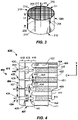
- FIG. 1 depicts an example embodiment of a continuous twin-screw extruder machine (TSM) 20.
- the twin-screw extruder machine 20 comprises a barrel 22 comprising chamber portions 24, 26 formed therein and in communication with each other.
- the barrel 22 can be monolithic or it can be formed from a plurality of barrel segments connected successively in the longitudinal (i.e., axial) direction.
- the chamber portions 24, 26 extend through the barrel 22 in the longitudinal direction from an upstream side 28 to a downstream side 30.
- a material supply port 32 which can comprise a hopper or other material supply structure, is provided for supplying the ceramic-forming mixture 29 to the extruder machine 20.
- An extrusion die 34 is provided at a discharge end 36 at the downstream side 30 of the barrel 22 for extruding the ceramic-forming mixture 29 into a desired shape, such as a honeycomb article or the like along direction 31.
- the extrusion die 34 can be coupled with respect to the discharge end 36 of the barrel 22, such as at a terminal end of the barrel 22.
- the extrusion die 34 can be preceded by other structures, such as a screen, screen support, and/or homogenizer (not shown), or the like to facilitate the formation of a steady plug-type flow front before the ceramic-forming mixture reaches the extrusion die 34.
- a pair of extruder screws 38, 40 are mounted in the barrel 22.
- First extruder screw 38 is rotatably mounted at least partially within one of the chamber portions 24, 26 while a second extruder screw 40 is rotatably mounted at least partially within the other of the chamber portions 24, 26.
- the first and second extruder screw 38, 40 can be arranged generally parallel to each other, as shown, though they can also be arranged at various angles relative to each other.
- Each of the first and second extruder screws 38, 40 can also be coupled to a driving mechanism 42 outside of the barrel 22 for rotation in the same or different directions. It is to be understood that both of the first and second extruder screws 38, 40 can be coupled to a single driving mechanism, or as shown, to individual driving mechanisms 42.
- the first and second extruder screws 38, 40 move the ceramic-forming mixture 29 through the chamber portions 24, 26 generally in direction 33 with a pumping and mixing action.
- Further support structures 35 (shown dotted) for supporting the first and second extruder screws 38, 40 may be provided.
- FIG. 2 is a schematic illustration of an end of an extruder 20 and shown with a honeycomb extrudate 200 being extruded therefrom.
- the extruder 20 is shown with extruder front end where the ceramic-forming mixture 29 exits the extruder 20 as the honeycomb extrudate 200.
- An extruder cartridge 102 coupled at an end of the extruder 20 comprises extrusion hardware such as an extrusion die 34 comprising a skin forming mask 104.
- the honeycomb extrudate 200 can comprise a plurality of channels and an outer peripheral surface 206.
- the honeycomb extrudate 200 thus comprises a honeycomb body.
- honeycomb extrudate 200 has a length L1 and comprises a first end face 202 and the outer peripheral surface 206 (skin) extending from the extruder front end to the first end face 202.
- a plurality of intersecting walls 208, 212 forms mutually adjoining channels 210 that extend in the extrusion direction 31 (also referred to herein as the axial direction or z-direction) to form a honeycomb matrix of intersecting walls 208, 212.
- intersecting thin walls 208 form a channel 210 extending in the extrusion direction as is shown by dashed lines for illustration.
- Intersecting thick walls 212 can have a greater thickness than intersecting thin walls 208 according to example embodiments as described further herein.
- a maximum cross-sectional dimension perpendicular to the axial direction 31 is indicated by dimension D1.
- the maximum dimension D1 may be a diameter of the first end face 202.
- the honeycomb extrudate 200 cross-section perpendicular to the axial direction 31 is a rectangular shape, the maximum dimension D1 may be a diagonal of an end face.
- extrusion is illustrated in FIG. 2 , this disclosure is not so limited, and extrusion can be horizontal, vertical, or at some incline thereto.
- Cell density of the honeycomb extrudate 200 comprising the honeycomb structure comprising thin walls 208 and thick walls 212 can be between about 100 and 1,500 cells per square inch (cpsi) (between about 15.5 and 232.5 cells per square cm). Each of the respective thin wall portions and thick wall portions may exhibit different cell densities. Cell wall thicknesses of the thin walls 208 and thick walls 212 can range from about 0.038 mm to about 1.5 mm (about 1.5 mil to 60 mil, where one mil is 0.001 inch). For example, the geometry of the honeycomb extrudate 200 may contain various combinations of cell density (cpsi) of the thin walls 208 and thick walls 212 therein.
- honeycomb extrudate 200 can comprise a rectangular honeycomb cell structure, but is not strictly limited to a square cell structure in cross-section.
- rectangular non-square, hexagonal, octagonal, triangular, rectangular, circular, elliptical, other curved shapes, or other suitable cell shapes or combination thereof, such as polygonal with rounded corners and/or arced walls, may be used.
- the external cross-sectional shape of the honeycomb extrudate 200 is illustrated as circular, it is also not so limited.
- the external cross-sectional shape can be elliptical, racetrack-shaped, square, rectangular, tri-lobed, asymmetrical, symmetrical, or other desired shapes, and combinations thereof.
- the wet honeycomb extrudate 200 Upon exiting the extruder 20 in axial direction, also referred to herein as extrusion direction 31, the wet honeycomb extrudate 200 stiffens and comprises a network of axially extending intersecting walls 208, 212 (webs) that form axially extending channels 210 and an axially extending outer peripheral surface 206.
- the intersecting walls 208, 212 and channels 210 form a honeycomb matrix 216.
- Disposed at the outer periphery of the honeycomb matrix 216 is the outer peripheral surface 206.
- the outer peripheral surface 206 may be a co-extruded skin (e.g., an integrally formed co-extruded skin).
- the outer peripheral surface 206 may comprise partial channels and an after-applied skin may be later applied.
- wet honeycomb extrudate 200 can be cut or otherwise formed into lengths of green honeycomb bodies via known methods. As used herein, wet honeycomb extrudate 200 refers to extrudate prior to drying.
- the ceramic-forming mixture upon exiting the front end of the extruder 20, is formed into the wet honeycomb extrudate 200 that can be cut to length L2 forming a second end face 218 to form a wet green honeycomb body 220. That is, wet green honeycomb body 220 can be cut from the wet green honeycomb extrudate 200.
- the outer peripheral surface 206 of the wet green honeycomb body 220 can extend axially from the first end face 202 to the second end face 218.
- the wet green honeycomb body 220 can be severed from the honeycomb extrudate 200. Severing can be done by wire cutting, saw cutting, such as a band saw or reciprocating saw, laser cutting, or other cutting means.
- the honeycomb body 220 can have a honeycomb structure, a length L2, and comprise the first end face 202, the second end face 218, and an outer peripheral surface 206 extending between the first end face 202 and the second end face 218.
- Intersecting walls 208, 212 form channels 210 that extend between the first and second end faces 202, 218 are shown in dashed lines for illustration.
- Some intersecting walls 212 can have a greater thickness than other intersecting walls 208 according to example embodiments as described herein.
- a honeycomb body 220 comprising a greater number of intersecting walls 208 having thinner walls than intersecting walls 212 having thicker walls is referred to herein as a "nested structure.”
- a nested structure can have at least twice as many or three times as many, or more, intersecting walls 208 that are thinner than intersecting walls 212 that are thicker.
- the axial direction is indicated by arrow 31 and a maximum cross-sectional dimension perpendicular to the axial direction is indicated by D1.
- the top face refers to the first end face 202 and the bottom face refers to the second end face 218 of the honeycomb body 220 positioned in FIG. 3 , otherwise the first and second end faces 202, 218 are not limited by the orientation of the honeycomb body 220.
- the first end face 202 can be an inlet face and the second end face 218 can be an outlet face of the honeycomb body 220.
- the outer peripheral surface 206 (e.g., skin) of the honeycomb body 220 extends axially between the first end face 202 and the second end face 218.
- the honeycomb body 220 can be a log that can undergo further processing prior to firing or the honeycomb body 220 can be a final-sized honeycomb structure substantially ready for firing.
- Thermal mass of honeycomb body can play a role in determining catalytic performance, for example, during cold start stages and low temperature engine cycles.
- Ever more stringent exhaust gas regulations highlight the long felt need for a honeycomb product with lower thermal mass and higher heat exchange surface area as well as larger open frontal area (OFA) with lower or equivalent back pressure than present conventional ceramic honeycomb products.
- OFA open frontal area
- honeycomb bodies incorporating greater number of cells are also in demand to provide additional surface area for catalyst application.
- current extrusion die designs can be adapted to the extrusion of thin-walled honeycomb bodies with no gross forming defects, certain new problems unique to these honeycomb bodies comprising such thinner walls may be encountered.
- One problem is that such thin-walled honeycomb bodies exhibit lower strength in the fired ceramic honeycomb bodies, which may lead to fractures and cracking during canning operations.
- a honeycomb body 220 with periodically thickened walls offers a synergistic combination of, in some embodiments, meeting the thermal mass requirements for fast light-off and low frontal area while also improving or maintaining ISO strength compared to prior art thin-walled honeycomb bodies.
- the thickness of the thick walls 212 and their periodicity can be determined by the strength requirements while achieving a targeted product thermal mass by incorporating the thin walls 212.
- having combinations of thin and thick walls 208, 212 presents forming challenges. Solving the challenge of developing extrusion dies to provide uniform flow across the face of such honeycomb bodies 220 comprising thin and thick walls 208, 212 can enable defect-free manufacture of these honeycomb bodies 220.
- extrusion apparatus honeycomb extrusion dies, and methods of forming honeycomb bodies are provided.
- the aforementioned apparatus, extrusion dies, and methods may provide for knit of walls with significantly different wall thicknesses to each other across the honeycomb body.
- honeycomb bodies that have a 2.8 mil (0.0711 mm) wall thickness with a tolerance of about a 0.0002 inch (0.005 mm) difference between thicknesses of various walls.
- walls with significantly different web thicknesses across the honeycomb body 220 can be provided using extrusion dies, extrusion apparatus, and extrusion methods described herein.
- extrusion dies, extrusion apparatus, and extrusion methods described herein may be used to extrude honeycomb bodies 220 having nested cell structures comprising combinations of thin walls 208 and thick walls 212 and that may comprise, for example, a 900/1.5/100/4.5 configuration comprising a 900/1.5 (139 cells per square cm (cpscm)/0.0381 mm) thin wall structure and a 100/4.5 (15.5 cpscm/0.114 mm) thick web structure.
- a 900/1.5/100/4.5 configuration comprising a 900/1.5 (139 cells per square cm (cpscm)/0.0381 mm) thin wall structure and a 100/4.5 (15.5 cpscm/0.114 mm) thick web structure.
- Other suitable examples comprising combinations of thin walls 208 and thick walls 212 of honeycomb bodies 220 having nested cell structures are possible. The above examples are illustrative only and not intended to be limiting.
- FIG. 4 A schematic diagram of a portion of an example honeycomb extrusion die 400 for extrusion of honeycomb bodies 220 with combinations of thin walls 208 and thick walls 212 is shown in cross section in FIG. 4 .
- the honeycomb extrusion die 400 is configured for extruding walls 208, 212 with significantly different web thicknesses across the honeycomb body 220.
- Honeycomb extrusion die 400 can have, for example, narrow discharge slots 427 of about 1.7 mils (0.043 mm) width and wide discharge slots 425 of about 5.1 mils (0.129 mm) width.
- Such an example honeycomb extrusion die 400 can achieve die extrusion pressures around 2,500 psi (17.24 MPa) at an extrusion speed of 1 inch/s (2.54 cm/s), for example.
- the honeycomb extrusion die 400 is not intended to be limited and can include configurations to extrude honeycomb bodies with two different wall thicknesses arranged in space with different repetition frequency.
- nested cell structures with cells arranged into rows (R) and columns (C) (such as a R ⁇ C of 3x3, 3x4, 3x5, 3x6, 4x4, 4x5, 4x6, 5 ⁇ 5, 5x6, 6x6, and the like) may be manufactured using the extrusion dies 400 described herein.
- R ⁇ C 3x3, 3x4, 3x5, 3x6, 4x4, 4x5, 4x6, 5 ⁇ 5, 5x6, 6x6, and the like
- Other thin wall 208 and thick wall 212 configurations are possible.
- extrusion dies 400-700 configured to extrude honeycomb bodies comprising walls of different thicknesses across the honeycomb bodies, referred to as nested cell honeycomb bodies, and nested cell honeycomb extrusion dies, are herein provided.
- FIG. 4 is a schematic cross-sectional side view of a honeycomb extrusion die 400 according to example embodiments.
- a discharge face 402 (exit face) of a die body 401 comprises an array of pins 406 spaced apart from one another in x- and y-directions (perpendicular to x and y) that define a honeycomb network of intersecting discharge slots 410.
- the discharge slots 410 have a slot length extending in a z-direction.
- An inlet face 414 of the die body 401 is disposed opposite the discharge face 402 and spaced therefrom in the z-direction
- Each of the pins 406 comprises an outer surface comprising an inlet portion 416, an outlet portion 418, and an intermediate portion 420 disposed between the inlet portion 416 and the outlet portion 418 of each of the pins 406.
- the outlet portions 418 of the outer surfaces on at least some of the pins 406 define the discharge slots 410.
- the inlet portions 416 of the outer surface on at least some of the pins 406 interface with one or more axial feedholes 422 that extend in the z-direction and that intersect with at least some of the discharge slots 410.
- First outlet portions 424 of the outer surfaces of a plurality of the pins 406 define a plurality of thick (wide) discharge slots 425 having a wide slot exit width W1 (first width).
- Second outlet portions 426 of the outer surfaces of the plurality of pins 406 define a plurality of thin (narrow) discharge slots 427 having a narrow slot exit width W2 (second width), wherein the first width W1 is wider than the second width W2.
- the first width W1 is twice the second width or greater.
- the first width W1 is three, four, or more, times the second width W2.
- wide or thick refers to the first outlet portions 424 defining thick (wide) discharge slots 425 of width W1 and narrow or thin refers to the second outlet portions 426 defining thin (narrow) discharge slots 427 of width W2.
- the first surface indentation features 430 can extend deeper into each pin 406 than the second surface indentation features 434.
- FIG. 5 illustrates another example embodiment of an exit face 502 of a honeycomb extrusion die body 500.
- the exit face 502 comprises an array of pins 406 spaced apart from one another in x- and y-directions that define a honeycomb matrix of intersecting discharge slots 510 (slot exits).
- the slots extend in the z-direction (perpendicular to the page in FIG. 5 ).
- Axial feedholes 422 (shown dotted in FIG. 5 ) can be seen disposed at mid pin positions (between slot intersections) in the plan view of FIG. 5 .
- a skin forming region 512 can be disposed at a periphery of the exit face 502, wherein said skin forming region 512 may be produced by an interface of the die body 500 with a skin-forming mask.
- a first group of the first outlet portions 424 of the outer surfaces of the plurality of pins 406 having the first width W1 are disposed in the x-direction.
- the first group of the first outlet portions 424 can also be disposed periodically alternating in the x-direction with a first group of the second outlet portions 426 of the outer surfaces of the plurality of pins 406 having the second width W2.
- a second group of the first outlet portions 424 defining a second plurality of wide discharge slots 425 having the first width W1 extend in the y-direction.
- the second group of the first outlet portions 424 can be periodically alternating in the y-direction with a second group of the second outlet portions 426 defining a second plurality of narrow discharge slots 427 having the second width W2.
- the configuration of wide discharge slots 425 can form enclosures 520 that surround or enclose one or more narrow discharge slots 427.
- the configuration of wide discharge slots 425 of FIG. 5 forms rectangular (e.g., square) enclosures 520 that enclose two parallel narrow discharge slots 427 extending in the x-direction and two parallel narrow discharge slots 427 extending in the y-direction.
- each pin block defines a plurality of narrow discharge slots 427 and at least partially defines a plurality of wide discharge slots 425.
- each pin block comprises a plurality of pins 406 that define a subset of the narrow discharge slots 427 and that do not define any of the wide discharge slots 425.
- Each pin block further comprises a plurality of pins that define both a second subset of the narrow discharge slots 427 and a subset of the wide discharge slots 425.
- at least two directly adjacent closed pin blocks share at least one wide discharge slot 425.
- each closed extrusion pin block has a periphery that is defined by wide discharge slots 425.
- each closed extrusion pin block comprises a plurality of pins 406 arranged into rows (R) and columns (C).
- each closed extrusion pin block has three rows and three columns of pins, as shown in, for example, FIG. 5 .
- R x C i.e., "R by C” or "R rows by C columns”
- 3x3, 3x4, 3x5, 3x6, 4x4, 4x5, 4x6, 5x5, 5x6, and 6x6 may also be used.
- the x-direction is substantially perpendicular to y-direction, but the disclosure is not so limited and the y-direction can be disposed at other angles relative to the x-direction, such as nearly 60 degrees for honeycomb die bodies having outer surfaces of die pins in the outlet portion having hexagonal shapes.
- the intersecting array 510 can have wide discharge slots 425 of the first width W1 and narrow discharge slots 427 of the second width W2.
- the intersecting array 510 can have some wide discharge slots 425 of the first width W1 extending in the x-direction, referred to herein as the first group, and some wide discharge slots 425 of the first width W1 extending in the y-direction, referred to herein as a second group.
- the intersecting array 510 can have some narrow discharge slots 427 of the second width W2 extending in the x-direction in a first group and some narrow discharge slots 427 of the second width W2 extending in the y-direction in the second group.
- the intersecting array 510 can have some wide discharge slots 425 extending in the x-direction, some wide discharge slots 425 extending in the y-direction, some narrow discharge slots 427 extending in the x-direction, and some narrow discharge slots 427 extending in the y-direction.
- the intersecting array 510 can have one or more wide discharge slots 425 of the first width W1 extending in a first direction, and one or more narrow discharge slots 427 of the second width W2 extending parallel to the first direction.
- the first direction can be the x-direction or the y-direction.
- one or more narrow discharge slots 427 can be disposed between two of the wide discharge slots 425.
- two or more narrow discharge slots 427 can be interposed between two adjacent ones of the wide discharge slots 425.
- the intersecting array 510 can have wide discharge slots 425 of the first width W1 extending in a first direction (e.g., the x-direction), and wide discharge slots 425 of the first width W1 extending in a second direction (e.g. the y-direction) orthogonal to the first direction.
- FIGs. 4 , 5 , 6 , 7 , and 8 show the ratio of the number of a first group of narrow discharge slots 427 having the second width W2 extending in the x-direction to the number of a first group of wide discharge slots 425 having the first width W1 extending in the x-direction is two, the ratio can be greater than two.
- the ratio of the number of second group of narrow discharge slots 427 having the second width W2 extending in the y-direction to the number of a second group of wide discharge slots 425 having the first width W1 extending in the y-direction can be two or greater.
- the first outlet portions 424 of the first group intersect first outlet portions 424 of the second group and the first outlet portions 424 of the first group intersect second outlet portions 426 of the second group.
- the second outlet portions 426 of the first group intersect first outlet portions 424 of the second group and the second outlet portions 426 of the first group intersect second outlet portions 426 of the second group.
- first inlet portions 438 of the side surfaces 407 of the plurality of pins 406, which include the first outlet portions 424, are spaced apart to define a first plurality of divot feed slots 440 having a first inlet width W5.
- Second inlet portions 442 of the outer surfaces of the pins 406 are spaced apart to define a second plurality of inlets 444 having a second inlet width W6.
- the first inlet width W5 can be substantially equal to the second inlet width W6.
- the second inlet width W6 can be substantially equal to the width W4.
- first surface indentation features 430 extend laterally deeper into each pin 406 than the first inlet portions 438.
- the first outlet portions 424 can extend laterally deeper into each pin 406 than the first inlet portions 438.
- a divot floor portion 446 is shown between the first intermediate portion 428 and the first inlet portion 438.
- the feedholes 422 can intersect with inlet portions 416 at a position that is mid pin as shown in FIG. 4 .
- the feedholes 422 can extend deeper into each pin 406 than the second surface indentation features 434 (e.g., plenums).
- the feedholes 422 can extend deeper into each pin 406 than the divots 430.
- the feedholes 422 can extend deeper into each pin 406 than the first surface indentation features 430 (e.g., divots) and the second surface indentation features 434 (e.g., plenums).
- the feedholes 422 do not intersect with the first surface indentation features 430 (e.g., divots). In some embodiments, the feedholes 422 can intersect with the second surface indentation features 434 (e.g., plenums).
- the feedholes 422 can intersect with inlet portions 416 of the outer surfaces of the plurality of pins 406.
- the inlet portions 416 of the outer surface on at least some of the pins 406 intersect with one or more of the feedholes 422 on x-z inlet portions of the outer surface of the pins 406 (e.g., for discharge slots that extend along the x direction).
- the inlet portions 416 of the outer surface on at least some of the pins 406 intersect with one or more of the feedholes 422 on y-z inlet portions of the outer surface of the pins 406 (e.g., for discharge slots that extend along the y-direction).
- the inlet portions 416 of the outer surface on at least some of the pins 406 intersect with one or more of the feedholes 422 on an x-z inlet portion and a y-z inlet portion of the outer surface of the pins 406. In some embodiments, the inlet portions 416 of the outer surfaces on all of the pins 406 have feedholes 422 on x-z inlet portions and y-z inlet portions of the outer surfaces of the pins 406.
- FIG. 6 illustrates another example embodiment of an outlet end 602 of a honeycomb extrusion die body 600.
- the honeycomb extrusion die body 600 is the same as that shown in FIG. 5 except for the position of the feedholes 422.
- the outlet end 602 comprises an array of pins 406 spaced apart from one another in x- and y-directions that define a honeycomb network of intersecting discharge slots extending in a z-direction perpendicular to the page in FIG. 6 .
- Feedholes 422 can be seen disposed at corner positions of the die pins 406 in the plan view of FIG. 6 , i.e. at the intersections of the respective slots.
- a die body can have feedholes 422 disposed at mid pin positions as shown in FIG. 5 and also at corner positions as shown in FIG. 6 .
- FIG. 6 An enlargement of a portion of the honeycomb extrusion die body 600 shows details of the outlet end 602 at the bottom of FIG. 6 .
- the first width W1 of the wide discharge slots 425 is shown in solid lines between outer surfaces of adjacent pins 406, the divot width W3 is shown in dashed lines between outer surfaces of adjacent pins 406, and the divot feed slot width W5 is shown in solid lines.
- the second width W2 of the narrow discharge slots 427 is shown in solid lines between outer surfaces of adjacent pins 406 and the plenum width W4 is shown in dashed lines between outer surfaces of adjacent pins 406.
- FIG. 7 is a schematic diagram of a portion of an outlet face of a honeycomb die body 700.
- a honeycomb network 702 can have wide discharge slots 425 of the first width W1 that intersect at large orthogonal intersections 710, and narrow discharge slots 427 of the second width W2 that intersect at narrow orthogonal intersections 712.
- the inlet portions of the pins 406 immediately adjacent the large orthogonal intersections 710 can comprise first feedholes 422a of a first hydraulic diameter.
- the inlet portions of the pins 406 immediately adjacent the narrow orthogonal intersections 712 can comprise second feedholes 422b of a second hydraulic diameter, wherein the first hydraulic diameter can be larger than the second hydraulic diameter.
- Feedholes 422 are located at the intersections of the narrow discharge slots 427 and at the intersections of the wide discharge slots 425. In the depicted embodiment, the intersections of the wide discharge slots 425 with the narrow discharge slots 427 are shown devoid of feedholes.
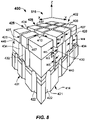
- FIG. 8 is a schematic isometric diagram of a portion of the honeycomb extrusion die 400 according to some example embodiments disclosed herein.
- the honeycomb extrusion die 400 shown in the illustrated embodiment comprises a die body 401, an inlet face 414, and a discharge face 402 (exit face) opposite the inlet face 414 in the z-direction.
- Inlet openings 421 in the inlet face 414 extend into the die body 401 to form feedholes 422.
- Die pins 406 disposed on the discharge face 402 comprise outer or side surfaces 407 extending into the die body 401.
- the side surfaces 407 define an intersecting array 510 of discharge slots 410 between adjacent side surfaces 407 of adjacent pins 406.
- the intersecting array 510 of discharge slots 410 comprises wide discharge slots 425 of width W1 extending from the discharge face 402 into the die body 401 to first surface indentation features 430 (e.g., divots) of width W3.
- the width W3 is greater than first width W1.
- the first surface indentation features 430 e.g., divots
- the divot feed slots 440 extend into the die body 401 from the divots 430 and are in fluid communication with the feedholes 422 in use.
- the intersecting array 510 of discharge slots 410 further comprises narrow discharge slots 427 of width W2 extending into the die body 401 from the discharge face 402 to plenums 434 or second surface indentation features.
- the plenums 434 have a width W4, which is greater than width W2.
- the second surface indentation features 434 (e.g., plenums) of width W4 extend into the die body 401 from the narrow discharge slots 427 and are in fluid communication with the feedholes 422 in use.
- the positions of the wide discharge slots 425 alternate with the position of the narrow discharge slots 427 across the discharge face 402 in a first direction, such as an x-direction.
- the positions of the wide discharge slots 425 can also alternate with the position of the narrow discharge slots 427 across the discharge face 402 in a second direction, such as a y-direction.
- the intersecting array of discharge slots 410 can further comprise at least two narrow discharge slots 427 to every one wide discharge slot 425 (i.e., a ratio of 2 narrow discharge slots 427 for each one of the wide discharge slots 425). Tradeoffs between isostatic strength and fast light-off characteristics of a honeycomb body having alternating thick and thin walls can determine the number of narrow discharge slots 427 to every one wide discharge slot 425.
- the intersecting array of discharge slots 410 can comprise at least two narrow discharge slots 427 to every one wide discharge slot 425, at least three narrow discharge slots 427 to every one wide discharge slot 425, at least four narrow discharge slots 427 to every one wide discharge slot 425, or even at least five narrow discharge slots 427 to every one wide discharge slot 425.
- the intersecting array 510 of discharge slots 410 is shown as disposed in a rectilinear pattern with the discharge slots 410 extending in the x-direction and the y-direction.
- the arrangement of the intersecting array 510 of discharge slots 410 comprising wide discharge slots 425 and narrow discharge slots 427 is not so limited, and may comprise discharge slots 410 arranged in other honeycomb patterns of intersecting slots.
- the intersecting array 510 of discharge slots 410 can be rectilinear, hexagonal, triangular radial, asymmetric, other polygonal, other curvilinear, or combinations thereof.
- each die pin side surface 407 meets another die pin side surface 407 of the same die pin 406 at a corner region and mid pin regions can be disposed between the corner regions.
- the feedholes 422 can be disposed overlapping in the z-direction with the mid pin regions.
- the feedholes 422 and the discharge slots 410 are in fluid communication and the feedholes are configured to supply ceramic-forming mixture to the discharge slots.
- the feedholes 422 can be disposed overlapping in the z-direction with the corner regions, i.e., located at some slot intersections.
- the feedholes 422 can be disposed overlapping in the z-direction with the mid pin regions and also with the corner regions.
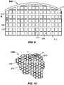
- FIGs. 9 and 10 illustrate further example embodiments of portions of extruded honeycomb structures 900, 1000 having nested channel arrangements.
- the full structures 900, 1000 can continue with the nested cell structures as shown to the periphery of the honeycomb bodies 900, 1000.
- FIG. 9 shows an extruded honeycomb structure 900 comprising first intersecting walls (thick walls 212) having a first thickness t1 and second intersecting walls (thin walls 208) having a second thickness t2, which is less than the first thickness t1.
- the first intersecting walls 212 and second intersecting walls 208 form channels 210 (a few labeled).
- the intersecting walls 212 can provide substantial isostatic strength to the extruded honeycomb structure 900 and form repeating nested structures within the honeycomb structure 900.
- the second intersecting walls 208 can provide substantial reduction in thermal mass and higher heat exchange surface area for fast light-off properties as well as larger open frontal area (OFA) for lower back pressure than a honeycomb structure that comprises substantially all thin walls.
- FIG. 10 shows an example embodiment of a honeycomb structure 1000 comprising channels 210 having a hexagonal-shape in transverse cross section.
- the first intersecting walls (thick walls 212) of first width t1 and second intersecting walls (thin walls) 208 of second width t2 form the channels 210.
- the die bodies disclosed herein can be implemented in other die geometries to yield other honeycomb body configurations comprising nested cell structures disclosed therein, wherein segments of thin walls 208 are bounded by thick walls 212.
- the nested cell structures comprising thick walls 212 and thin walls 208 can substantially increase ISO strength as compared to a honeycomb structure that comprises substantially all thin walls.
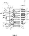
- the honeycomb extrusion die 400 comprises an impedance plate 460 disposed directly adjacent, or in proximity, to the inlet face 414 of the die body 401 and upstream of the die body, as shown in the cross-sectional schematic diagrams of FIGs. 4 and 11 .
- the impedance plate 460 in the illustrated embodiments can comprise an entrance face 461, an exit face 463, and entrance openings in the entrance face 461 extending through the impedance plate 460 to the exit face 463 to form impedance holes 462. At least some of the impedance holes 462 correspond to the inlet openings 421 for the feedholes 422 in the inlet face 414 of the die body 401.
- At least one impedance hole 464 can have a different radius and/or different length than another impedance hole 470 to balance impedance of ceramic-forming mixture flowing into and through the die body 401.
- holes may have different radii and/or lengths at different locations within the impedance plate 460.
- a first set of holes 462 may have a first radius, while a second set of holes 462 may have second radius that is different (e.g., smaller or larger) from the second radius.
- a first set of holes 462 may have a first length, while a second set of holes 462 may have second length that is different (e.g., smaller or larger) from the second length.
- the impedance holes 462 correspond to feedholes 422 in the die 400 and are configured to permit and/or direct flow of ceramic-forming mixture into the feedholes 422, while other portions of the impedance plate 460 partially or completely block ceramic-forming mixture from flowing into the feedholes.
- the impedance plate 460 can comprise one or more impedance blocks 473 that block at least one of the inlet openings 421 at the inlet face 414 of the die body 401.
- the impedance plate 460 may end at an edge 472 and may be disposed on a portion of the inlet face 414.
- the radius of the impedance holes 462 will depend on the thickness of the wide and narrow slots, the wide-to-narrow slot ratio, the feedhole radius, and feedhole locations. In some embodiments, the radius of the impedance holes is between 3 mils (0.08 mm) and 11 mils (0.28 mm).
- impedance plates may comprise small impedance holes with a 6 mil (0.15 mm) radius and large impedance holes with varying diameters between a value greater than 6 mil (0.15) and a value of 9 mil (0.23).
- FIG. 11 illustrates a schematic cross-sectional view of a honeycomb extrusion die body 1100 according to example embodiments showing first intermediate portions 428 and first inlet portions 438 of the outer surfaces of the pins 406 intersecting narrow discharge slots 427 and wide discharge slots 425.
- FIG. 11 differs from FIG. 4 , which shows second intermediate portions 432 intersecting narrow discharge slots 427 and wide discharge slots 425.
- the divot feed slots 440 intersect a first portion of feedholes 422 and can extend into the first portion of feedholes by a depth D1.
- the second surface indentation features 434 e.g., plenums
- depth D2 may be greater than depth D1.
- FIG. 12 is a schematic cross-sectional view of a honeycomb die body 1200 according to example embodiments showing shallow feedholes 422c intersecting the first inlet portions 438 of the outer surfaces of the pins 406. Deeper feedholes 422d can intersect the second surface indentation features 434 (e.g., plenums).
- the divot feed slots 440 intersect a first portion of feedholes 422c and the second surface indentation features 434 (e.g., plenums) intersect a second portion of feedholes 422d, wherein the second portion of feedholes 422d extend from the inlet face 414 into the honeycomb die body 1200 in the z-direction a greater distance than the first portion of feedholes 422c.
- FIG. 12 also shows an example of first surface indentation features 430 (e.g., divots) having tapered first intermediate portions 428.
- the first surface indentation features 430 e.g., divots may maintain their widest width W3 even with the tapered first intermediate portions 428).
- an extruder machine 20 can comprise an extrusion die 34 attached to a discharge end 36 of the extruder machine 20.
- the honeycomb extrusion die 400 ( FIGs. 4 and 8 ) can comprises a die body 401, an inlet face 414, and a discharge face 402 (outlet face) opposite the inlet face 414 in a z-direction.
- Inlet openings 421 in the inlet face 414 can extend into the die body 401 to form feedholes 422.
- Die pins 406 disposed on the discharge face 402 comprise outer or side surfaces 407 extending into the die body 401.
- the intersecting array of discharge slots 410 can comprise wide discharge slots 425 of first width W1 extending from the discharge face 402 into the die body 401 to first surface indentation features 430 (e.g., divots).
- the first surface indentation features 430 e.g., divots
- the first surface indentation features 430 have a width W3, which is greater than the first width W1.
- the first surface indentation features 430 extend into the die body 401 from the wide discharge slots 425 to divot feed slots 440.
- the divot feed slots 440 have width W5, which is less than the first width W1.
- the divot feed slots 440 extend into the die body 401 from the first surface indentation features 430 (e.g., divots) and are in fluid communication with the feedholes 422 in use.
- the intersecting array of discharge slots 410 according to the illustrated embodiment comprises narrow discharge slots 427 of second width W2, which is less than first width W1, extending into the die body 401 from the discharge face 402 to second surface indentation features 434 (e.g., plenums).
- the second surface indentation features 434 (e.g., plenums) have a width W4, which can be greater than the second width W2.
- the plenums 434 extend into the die body 401 from the narrow discharge slots 427 and are in fluid communication with the feedholes 422.
- honeycomb extrusion die e.g., any of the honeycomb extrusion die bodies 400, 500, 600, 700, 1100, and 1200 described herein.
- the honeycomb extrusion die comprises a die body, an inlet face, a discharge or exit face opposite the inlet face in an extrusion direction, inlet openings in the inlet face extending into the die body to form feedholes, and die pins disposed on the discharge face comprising side surfaces extending into the die body.
- Side surfaces of the die pins define an intersecting array of discharge slots between adjacent side surfaces of adjacent pins.
- the intersecting array of discharge slots comprise wide discharge slots of a first width W1 which are connected with the feedholes.
- the narrow discharge slots have second width W2, which is less than the first width W1. Both the narrow discharge slots and the wide discharge slots are connected to the feedholes.
- the ceramic-forming mixture exits the intersecting array of discharge slots at the discharge face as a honeycomb extrudate.
- the method can comprise selectively restricting the ceramic-forming mixture to a portion of the inlet openings, for example, by utilizing the impedance plate 460 described above and shown in FIGs. 4 and 11 .
- the method of forming honeycomb bodies can comprise cutting, drying, and firing the honeycomb extrudate that has been extruded through the honeycomb extrusion die to form a porous ceramic honeycomb body (e.g., 220, 900, 1000).
- the porous honeycomb body comprises a first end face, a second end face and nested intersecting cell walls extending from the first end face to the second end face forming channels therebetween.
- the intersecting cell walls comprise first cell walls of first width t1 and second cell walls of second width t2 that is greater than the first width t1. The position of the first cell walls alternate with the position of the second cell walls across the honeycomb body transverse to the extrusion direction.
- the honeycomb body can comprise one first cell wall to every one second cell wall. In other embodiments, the honeycomb body can comprise at least two second cell walls to every one first cell wall.
- the ceramic-forming mixture can comprise a ceramic precursor or a ceramic material or both that is transformed or sintered upon firing into a porous ceramic material that comprises cordierite, aluminum titanate, silicon nitride, silicon carbide, mullite, or combinations thereof.
- Example embodiments can provide honeycomb structures with both relatively thick and ultrathin walls, which can alternate periodically.
- Thin walls 208 (and corresponding narrow slot thickness) can be less than 2.5 mil (0.0635 mm) as thin as 1.5 mil (0.038 mm) and the thick walls 212 (and corresponding wide slot thickness) can be 4 mils (0.102 mm) or more, or even 5 mils (0.127 mm) or more.
- the thick-to-thin web thickness ratio (and corresponding wide-to-narrow slot ratio) can be as high as 1.5 or more, 2 or more, 2.5 or more, 3 or more, or even 4 or more, and can be between 2 and 4, or even between 2.5 and 4, or even 3 and 4 in some embodiments.
- example embodiments provide apparatus and methods to achieve cell densities of up to 900 cpsi having the above-described nested cell arrangement.
- the disclosed extrusion dies can comprise both wide and narrow slots, balancing of impedance, and preventing cross talk between wide slots and narrow slots. Uniform extrusion speed across the extrusion die provides moderate pressure drop and economically efficient extrusion speeds.
- different outer surface shapes can be disposed on the same pin to define the different slot geometries.
- the mid-pin feedholes can provide for control of cross talk, and the impedance plate 460 may provide control of local impedance.
- a different slot width above and below the first surface indentation feature (e.g., divot) can provide another control means to mitigate cross talk.
- the narrow slots can comprise a slender plenum structure to reduce flow impedance and reduce web swelling. Inclusion of the first surface indentation features (e.g., divot) in the wide slots can provide a similar impedances as the narrow slots to achieve flow front balance.
- Example embodiments of the disclosure are further described below with respect to specific structures thereof, which are illustrative only and not intended to be limiting.
- a summary of the extrusion die performance is provided in Table 1. The results are from modeling the velocity distribution at the outlet of the nested structure die having wide slots and thin slots. Table 1 Structural Features Performance Run Plenum Divot Impedance Plate Die pressure (psi) dV percent (%) 1 No No No 2006 75.4 2 Yes Yes No 2234 22.9 3 Yes Yes Yes 2551 9.5
- FIGs. 13A, 13B, and 13C correspond to the results of Runs 1, 2, and 3 in Table 1.
- the parameter dV% is used to determine extrusion performance and represents the flow uniformity at the exit from the extrusion die.
- the die pressure (psi) is the pressure across the extrusion die. As Table 1 shows, the combination of features disclosed herein can reduce dV% by about ten times.
- FIG. 13A shows the intersection of a wide discharge slot 425 and a narrow discharge slot 427 in a model.
- Results of a wide discharge slot 425 intersecting a narrow discharge slot 427 is a dV% of 75.4% indicating cross talk and an uneven flow front.
- FIG. 13B illustrates the addition of a first surface indentation feature 430 (e.g., divot) in the wide discharge slot 425 shown by first intermediate portion 428 of the outer surfaces of the plurality of pins 406, which comprise the first outlet portions 424.
- a second surface indentation feature 434 (e.g., plenum) is added to the narrow discharge slots 427 in the model is also shown in FIG. 13B .
- the plenum is shown by second intermediate portions 432 of the outer surfaces of the plurality of pins 406, which include the second outlet portions 426.
- first surface indentation feature 430 e.g., divot
- second surface indentation feature 434 e.g., plenum
- FIG. 13C shows the model with the impedance plate 460 added to the model of FIG. 13B .
- Having a divot added to the wide discharge slot 425, a plenum added to the narrow discharge slot 427, and the impedance plate 460 to selectively restrict ceramic-forming mixture to predetermined feedholes 422 reduced the dV% to 9.5%, indicating significant drop in cross talk and significant improvement in flow front uniformity.
- the model arrangement illustrated in FIG. 13C was used and the extrusion speed was reduced to 0.5 inch/sec at the die outlet and the inlet pressure was 2132 psi (14.70 MPa), dV% was 7.5%.
- FIG. 14 shows a partial cross-sectional view of the honeycomb extrusion die 400 with references to different dimensions therein.
- Table 2 provides example dimensions provided in the honeycomb extrusion die 400 of FIG. 14 .
- the feedholes 422 may be located in different positions within the honeycomb extrusion die 400.
- the feedholes 422 may be located at the intersections of the wide discharge slots 425 and the narrow discharge slots 427 as shown in FIG. 6 .
- the feedholes 422 may be located in the mid sections of wide discharge slots 425 and the narrow discharge slots 427 as shown in FIG. 5 .
- the diameters of the feedholes 422 may vary such that they are different at different locations.
- the diameters of the feedholes 422 may be varied in addition to or in lieu of the impedance plate 460 of FIG. 11 .
- the feedholes 422 may also have different depths, which can dictate the flow rate through the feedholes 422. For example, short depth feedholes 422 enable less or slower flow than deeper feedholes 422. Examples of feedholes 422 with different depths are shown in FIG. 12 .
Claims (14)
- Wabenextrusionsmatrize, Folgendes aufweisend:einen Matrizenkörper, Folgendes aufweisend:eine Einlassseite (414);eine Auslassseite (402, 502);mehrere Stifte (406), die auf der Auslassseite (402, 502) angeordnet sind und dazu angeordnet sind, eine Matrize einander schneidender Schlitze zu definieren, wobei die einander schneidenden Schlitze breite Schlitze und schmale Schlitze (427), die zwischen den breiten Schlitzen (425) ausgebildet sind, aufweisen, wobei die breiten Schlitze (425) eine Breitschlitzaustrittsbreite (W1) aufweisen, die größer ist als eine Schmalschlitzaustrittsbreite (W2) der schmalen Schlitze (427); undZuführöffnungen (422) an der Einlassseite (414), die Einlassabschnitte zu mindestens einem der breiten Schlitze (425) und der schmalen Schlitze (427) schneiden;wobei mindestens einige der Stifte (406), die die breiten Schlitze (425) definieren, ein erstes Flächenvertiefungsmerkmal (430) aufweisen, das (i) sich zwischen dem Einlassabschnitt und einem Breitschlitzaustritt eines breiten Schlitzes (425) befindet und (ii) von dem Breitschlitzaustritt beabstandet ist;wobei mindestens einige der Stifte (406), die die schmalen Schlitze (427) definieren, ein zweites Flächenvertiefungsmerkmal (434) aufweisen, das (i) sich zwischen dem Einlassabschnitt und einem Schmalschlitzaustritt eines schmalen Schlitzes (427) befindet und (ii) von dem Schmalschlitzaustritt beabstandet ist; undwobei die Matrize aus einander schneidenden breiten Schlitzen (425) und schmalen Schlitzen (427) mindestens ein Gehäuse (520) aus breiten Schlitzen (425), die mindestens einen schmalen Schlitz (427) umschließen, ausbildet;wobei die Wabenextrusionsmatrize dadurch gekennzeichnet ist, dassein oder mehrere breite Schlitze (425) einen ersten Abschnitt, der sich zwischen den Breitschlitzaustritten und dem ersten Flächenvertiefungsmerkmal (430) erstreckt, und einen zweiten Abschnitt, der sich zwischen Einlassabschnitten der breiten Schlitze (425) und dem ersten Flächenvertiefungsmerkmal (430) erstreckt, aufweisen, wobei die Breite (W1) des ersten Abschnitts größer ist als die Breite (W5) des zweiten Abschnitts.
- Wabenextrusionsmatrize nach Anspruch 1, wobei sich eine erste Gruppe schmaler Schlitze (427) in dem mindestens einen Gehäuse (520) in eine erste Richtung erstreckt und wobei sich eine zweite Gruppe schmaler Schlitze (427) in dem mindestens einen Gehäuse in eine zweite Richtung erstreckt.
- Wabenextrusionsmatrize nach Anspruch 1 oder 2, wobei die mehreren Stifte (406) in einem sich wiederholenden Muster mehrerer umschlossener Stiftblöcke angeordnet sind, wobei jeder umschlossene Stiftblock schmale Schlitze (427) definiert und zumindest teilweise breite Ablassschlitze (425) definiert.
- Wabenextrusionsmatrize nach Anspruch 3, wobei jeder umschlossene Stiftblock mehrere Stifte (406) aufweist, die einen Teilsatz der schmalen Schlitze (427) definieren und die keinen der breiten Schlitze (425) definieren.
- Wabenextrusionsmatrize nach Anspruch 4, wobei jeder umschlossene Stiftblock ferner mehrere Stifte (406) aufweist, die sowohl einen zweiten Teilsatz der schmalen Schlitze (427) als auch einen Teilsatz der breiten Schlitze (425) definieren.
- Wabenextrusionsmatrize nach einem der Ansprüche 1-5, wobei die Zuführöffnungen (422) erste Zuführöffnungen, die Einlassabschnitte zu den breiten Schlitzen (425) schneiden, und zweite Zuführöffnungen, die Einlassabschnitte zu den schmalen Schlitzen (427) schneiden, aufweisen.
- Wabenextrusionsmatrize nach einem der Ansprüche 1-6, wobei die ersten Flächenvertiefungsmerkmale (430) tiefer sind als die zweiten Flächenvertiefungsmerkmale (434) .
- Wabenextrusionsmatrize nach einem der Ansprüche 1-7, wobei mindestens einige der breiten Schlitze (425) andere schmale Schlitze (427) entlang der Breit-Schmal-Schlitzüberschneidungen schneiden.
- Wabenextrusionsmatrize nach einem der Ansprüche 1-8, wobei die Zuführöffnungen (422) von den Breit-Schmal-Schlitzüberschneidungen beabstandet sind.
- Wabenextrusionsmatrize nach einem der Ansprüche 1-9, wobei mindestens einige der schmalen Schlitze (427) andere schmale Schlitze (427) entlang der Schmal-Schmal-Schlitzüberschneidungen schneiden.
- Wabenextrusionsmatrize nach Anspruch 10, wobei die Zuführöffnungen (422) von den Schmal-Schmal-Schlitzüberschneidungen beabstandet sind.
- Wabenextrusionsmatrize nach einem der Ansprüche 1-11, wobei die Zuführöffnungen (422) von Überschneidungen zwischen beliebigen Schlitzüberschneidungen beabstandet sind.
- Wabenextrusionsmatrize nach einem der Ansprüche 1-12, wobei der Matrizenkörper zwei schmale Schlitze (427) pro breitem Schlitz (425) aufweist.
- Wabenextrusionsmatrize nach einem der Ansprüche 1-13, wobei die Breitschlitzaustrittsbreite (W1) mindestens dreimal größer ist als die Schmalschlitzaustrittsbreite (W2).
Applications Claiming Priority (3)
| Application Number | Priority Date | Filing Date | Title |
|---|---|---|---|
| US201762609477P | 2017-12-22 | 2017-12-22 | |
| US201762609485P | 2017-12-22 | 2017-12-22 | |
| PCT/US2018/065005 WO2019125830A1 (en) | 2017-12-22 | 2018-12-11 | Extrusion dies |
Publications (2)
| Publication Number | Publication Date |
|---|---|
| EP3727773A1 EP3727773A1 (de) | 2020-10-28 |
| EP3727773B1 true EP3727773B1 (de) | 2022-07-13 |
Family
ID=65228632
Family Applications (1)
| Application Number | Title | Priority Date | Filing Date |
|---|---|---|---|
| EP18859973.2A Active EP3727773B1 (de) | 2017-12-22 | 2018-12-11 | Extrusionsmatrize |
Country Status (3)
| Country | Link |
|---|---|
| US (2) | US11534937B2 (de) |
| EP (1) | EP3727773B1 (de) |
| WO (2) | WO2019125830A1 (de) |
Families Citing this family (2)
| Publication number | Priority date | Publication date | Assignee | Title |
|---|---|---|---|---|
| USD1004622S1 (en) * | 2018-02-20 | 2023-11-14 | Ngk Insulators, Ltd. | Catalyst carrier for exhaust gas purification |
| CN112838375B (zh) * | 2021-01-04 | 2022-06-24 | 北京环境特性研究所 | 一种X、Ku双频段透波的频率选择结构 |
Family Cites Families (72)
| Publication number | Priority date | Publication date | Assignee | Title |
|---|---|---|---|---|
| US3885977A (en) | 1973-11-05 | 1975-05-27 | Corning Glass Works | Anisotropic cordierite monolith |
| JPS573780Y2 (de) * | 1977-06-20 | 1982-01-23 | ||
| JPS547252A (en) | 1977-06-20 | 1979-01-19 | Hitachi Ltd | Program control system |
| JPS54110189U (de) | 1978-01-21 | 1979-08-02 | ||
| JPS54150406A (en) | 1978-05-18 | 1979-11-26 | Nippon Soken | Ceramic honeycomb structure |
| US4259057A (en) * | 1978-12-29 | 1981-03-31 | Saki Chemical Industry Co., Ltd. | Method of continuously extruding and molding ceramic honey-comb shaped moldings and die for use in the continuous extruding operation thereof |
| JPS5838083B2 (ja) | 1980-01-22 | 1983-08-20 | 株式会社日本自動車部品総合研究所 | ハニカム構造体押出成形用ダイス装置 |
| US4298328A (en) | 1980-05-12 | 1981-11-03 | Corning Glass Works | Extrusion apparatus for preventing the distortion of peripheral cells in extruded honeycomb structures |
| JPS5819743A (ja) | 1981-07-24 | 1983-02-04 | Pioneer Video Corp | 記録情報読取装置における光学系駆動装置 |
| JPS5819743U (ja) * | 1981-08-01 | 1983-02-07 | トヨタ自動車株式会社 | ハニカム構造体 |
| JPS6067111A (ja) | 1983-09-24 | 1985-04-17 | 日本碍子株式会社 | セラミツクハニカム構造体の押出し成形金型 |
| US4521532A (en) | 1984-04-23 | 1985-06-04 | General Motors Corporation | Monolithic catalytic converter for improved thermal performance |
| JPH0729285B2 (ja) * | 1986-07-11 | 1995-04-05 | 触媒化成工業株式会社 | ハニカム構造体の成形用ダイス |
| US4902216A (en) * | 1987-09-08 | 1990-02-20 | Corning Incorporated | Extrusion die for protrusion and/or high cell density ceramic honeycomb structures |
| US5238386A (en) * | 1992-05-20 | 1993-08-24 | Corning Incorporated | Multi-part extrusion die |
| US5332703A (en) | 1993-03-04 | 1994-07-26 | Corning Incorporated | Batch compositions for cordierite ceramics |
| DE19704144A1 (de) | 1997-02-04 | 1998-08-06 | Emitec Emissionstechnologie | Extrudierter Wabenkörper, insbesondere Katalysator-Trägerkörper, mit verstärkter Wandstruktur |
| JPH10264125A (ja) | 1997-03-28 | 1998-10-06 | Ngk Insulators Ltd | セラミックハニカム構造体 |
| KR20010015742A (ko) * | 1997-10-17 | 2001-02-26 | 알프레드 엘. 미첼슨 | 변형된 슬롯을 가진 압출다이 |
| JP4159155B2 (ja) | 1998-01-22 | 2008-10-01 | 株式会社日本自動車部品総合研究所 | セラミックハニカム構造体および押出金型 |
| WO2000040521A1 (en) | 1998-12-31 | 2000-07-13 | Corning Incorporated | Low sintering temperature cordierite batch and cordierite ceramic produced therefrom |
| US6221308B1 (en) | 1999-04-20 | 2001-04-24 | Corning Incorporated | Method of making fired bodies |
| JP2003504827A (ja) | 1999-07-07 | 2003-02-04 | コーニング インコーポレイテッド | セラミックのマイクロ波乾燥方法 |
| US6299813B1 (en) | 1999-09-23 | 2001-10-09 | Corning Incorporated | Modified slot extrusion dies |
| JP2001261428A (ja) | 2000-03-14 | 2001-09-26 | Ngk Insulators Ltd | セラミックハニカム構造体 |
| DE10024038A1 (de) | 2000-05-13 | 2001-11-22 | Dmc2 Degussa Metals Catalysts | Wabenkörper aus einem keramischen Material mit verbesserter radialer Druckfestigkeit |
| KR20030036205A (ko) | 2000-06-01 | 2003-05-09 | 코닝 인코포레이티드 | 코디어라이트 몸체 |
| JP5052717B2 (ja) | 2001-05-02 | 2012-10-17 | 日本碍子株式会社 | ハニカム構造体、及びそれを用いたハニカムフィルター、コンバーターシステム |
| JP2003010616A (ja) | 2001-06-29 | 2003-01-14 | Ngk Insulators Ltd | ハニカム構造体 |
| JP4282960B2 (ja) | 2001-08-30 | 2009-06-24 | 日本碍子株式会社 | 高強度ハニカム構造体、その成形方法及びハニカム構造コンバーター |
| JP4210446B2 (ja) * | 2001-09-19 | 2009-01-21 | 日本碍子株式会社 | ハニカム押出成形用口金及びその製造方法 |
| ATE372449T1 (de) | 2001-12-03 | 2007-09-15 | Hitachi Metals Ltd | Keramischer wabenfilter |
| JP4294964B2 (ja) | 2002-03-15 | 2009-07-15 | 日本碍子株式会社 | セラミックスハニカム構造体の製造方法 |
| JP4567338B2 (ja) | 2002-03-28 | 2010-10-20 | 日本碍子株式会社 | セル構造体、セル構造体の製造方法、及び触媒構造体 |
| DE60336824D1 (de) | 2002-09-05 | 2011-06-01 | Ngk Insulators Ltd | Wabenstruktur |
| JP2004261623A (ja) | 2003-01-08 | 2004-09-24 | Ngk Insulators Ltd | ハニカム構造体 |
| JP4527963B2 (ja) | 2003-11-04 | 2010-08-18 | 日本碍子株式会社 | マイクロ波乾燥法 |
| FR2874647B1 (fr) | 2004-08-25 | 2009-04-10 | Saint Gobain Ct Recherches | Bloc filtrant a ailettes pour la filtration de particules contenues dans les gaz d'echappement d'un moteur a combustion interne |
| KR100753377B1 (ko) | 2004-12-27 | 2007-08-30 | 이비덴 가부시키가이샤 | 허니컴 구조체 및 시일재층 |
| KR100692942B1 (ko) | 2005-02-01 | 2007-03-12 | 이비덴 가부시키가이샤 | 허니컴 구조체 |
| US7384442B2 (en) | 2005-02-28 | 2008-06-10 | Corning Incorporated | Ceramic wall-flow filter including heat absorbing elements and methods of manufacturing same |
| KR20080005528A (ko) | 2005-04-05 | 2008-01-14 | 에스브이 프로브 피티이 엘티디 | 세라믹 스페이스 트랜스포머에서의 프로브 패드 구조 |
| WO2007000825A1 (ja) | 2005-06-27 | 2007-01-04 | Ibiden Co., Ltd. | ハニカム構造体 |
| JP4788497B2 (ja) | 2005-12-27 | 2011-10-05 | 株式会社デンソー | 六角ハニカム構造体 |
| JP4709002B2 (ja) | 2005-12-27 | 2011-06-22 | 株式会社デンソー | 六角セルハニカム構造体 |
| KR20080102196A (ko) | 2006-03-15 | 2008-11-24 | 도요다 지도샤 가부시끼가이샤 | 복수개의 육각셀로 구성된 허니콤 구조체 |
| JP5090751B2 (ja) | 2006-03-29 | 2012-12-05 | 日本碍子株式会社 | ハニカム構造体 |
| JP2007273537A (ja) | 2006-03-30 | 2007-10-18 | Tdk Corp | 多層基板及びその製造方法 |
| US7575793B2 (en) | 2006-03-31 | 2009-08-18 | Corning Incorporated | Radial cell ceramic honeycomb structure |
| US7596885B2 (en) | 2006-07-28 | 2009-10-06 | Corning Incorporated | Microwave drying of ceramic structures |
| US8974724B2 (en) | 2006-11-29 | 2015-03-10 | Corning Incorporated | Aluminum titanate batch compositions and method |
| EP2176188B1 (de) | 2007-07-31 | 2020-09-02 | Corning Incorporated | Verfahren zur herstellung von porösen keramischen filtern und zusammensetzungen zum auftragen auf keramische wabenkörper |
| JP2009190964A (ja) | 2007-10-15 | 2009-08-27 | Ibiden Co Ltd | ハニカム構造体の製造方法 |
| JP4996642B2 (ja) * | 2009-03-27 | 2012-08-08 | 日本碍子株式会社 | ハニカム構造体成形用口金およびその製造方法 |
| JP5452961B2 (ja) * | 2009-03-31 | 2014-03-26 | 日本碍子株式会社 | ハニカム構造体 |
| US20110206896A1 (en) | 2010-02-25 | 2011-08-25 | Mark Lee Humphrey | Ceramic Honeycomb Body And Process For Manufacture |
| US8591287B2 (en) | 2010-02-26 | 2013-11-26 | Corning Incorporated | Methods of fabricating a honeycomb extrusion die from a die body |
| JP5649836B2 (ja) | 2010-03-23 | 2015-01-07 | 日本碍子株式会社 | ハニカム触媒体 |
| JP5478309B2 (ja) | 2010-03-23 | 2014-04-23 | 日本碍子株式会社 | ハニカム構造体 |
| US8641942B2 (en) | 2010-05-12 | 2014-02-04 | Corning Incorporated | Laser scanning systems and methods for measuring extruded ceramic logs |
| KR101297059B1 (ko) * | 2010-12-08 | 2013-08-26 | 허정섭 | 대형 허니컴 성형체의 내부크랙 방지를 위한 세라믹스 압출 금형 구조 및 그를 이용한 대형 허니컴 성형체의 제조방법 |
| JP5785406B2 (ja) | 2011-03-18 | 2015-09-30 | 日本碍子株式会社 | ハニカム構造体 |
| JP5343996B2 (ja) | 2011-04-20 | 2013-11-13 | 株式会社デンソー | ハニカム構造体 |
| US9038284B2 (en) | 2011-11-29 | 2015-05-26 | Corning Incorporated | Systems and methods for efficient microwave drying of extruded honeycomb structures |
| US9132578B2 (en) | 2011-11-29 | 2015-09-15 | Corning Incorporated | Apparatus and method for skinning articles |
| JP2013202531A (ja) | 2012-03-28 | 2013-10-07 | Kubota Corp | ハニカムフィルター |
| US9005517B2 (en) | 2012-05-16 | 2015-04-14 | Corning Incorporated | Single-fire two-step soak method |
| WO2013175552A1 (ja) | 2012-05-21 | 2013-11-28 | イビデン株式会社 | ハニカムフィルタ、排ガス浄化装置、及び、排ガス浄化方法 |
| US20140084505A1 (en) | 2012-09-21 | 2014-03-27 | Elizabeth Marie Vileno | Blended aluminas to control aluminum titanate properties |
| US9446560B2 (en) | 2013-07-26 | 2016-09-20 | Corning Incorporated | Fast firing method for high porosity ceramics |
| US9452578B2 (en) | 2013-07-26 | 2016-09-27 | Corning Incorporated | Fast firing method for high porosity ceramics |
| MX2017001123A (es) | 2014-07-25 | 2017-10-04 | Corning Inc | Estructuras tipo panal tolerantes a defectos. |
-
2018
- 2018-12-11 EP EP18859973.2A patent/EP3727773B1/de active Active
- 2018-12-11 WO PCT/US2018/065005 patent/WO2019125830A1/en unknown
- 2018-12-11 US US16/955,137 patent/US11534937B2/en active Active
- 2018-12-16 WO PCT/US2018/065893 patent/WO2019125971A1/en active Application Filing
- 2018-12-16 US US16/954,250 patent/US11745384B2/en active Active
Also Published As
| Publication number | Publication date |
|---|---|
| US20200316814A1 (en) | 2020-10-08 |
| US20210362370A1 (en) | 2021-11-25 |
| WO2019125971A1 (en) | 2019-06-27 |
| US11745384B2 (en) | 2023-09-05 |
| US11534937B2 (en) | 2022-12-27 |
| EP3727773A1 (de) | 2020-10-28 |
| WO2019125830A1 (en) | 2019-06-27 |
Similar Documents
| Publication | Publication Date | Title |
|---|---|---|
| EP3414067B1 (de) | Extrusionskomponenten für wabenkörper | |
| EP3344365B1 (de) | Keramische wabenkörper, wabenextrusionswerkzeuge und verfahren zur herstellung keramischer wabenkörper | |
| EP3727773B1 (de) | Extrusionsmatrize | |
| US20160096305A1 (en) | Die Assembly And Method Of Extruding Cellular Ceramic Substrates With A Skin | |
| US11554339B2 (en) | Plugged honeycomb bodies, extrusion dies and methods of manufacturing thereof | |
| US11312662B2 (en) | High isostatic strength honeycomb structures and extrusion dies therefor | |
| US7294301B2 (en) | Die assembly and method for forming honeycomb filters | |
| US20210220767A1 (en) | Honeycomb bodies with triangular cell honeycomb structures and manufacturing methods thereof | |
| US11752679B2 (en) | Honeycomb extrusion dies and forming methods | |
| US11813597B2 (en) | Honeycomb bodies with varying cell densities and extrusion dies for the manufacture thereof | |
| US11839995B2 (en) | Honeycomb bodies with honeycomb structure strengthening features and extrusion dies therefor | |
| US20220314489A1 (en) | Honeycomb extrusion dies and forming methods | |
| US11666897B2 (en) | Honeycomb bodies with multi-zoned honeycomb structures and co-extrusion manufacturing methods | |
| WO2022251010A1 (en) | Honeycomb extrusion dies and methods of using and making same |
Legal Events
| Date | Code | Title | Description |
|---|---|---|---|
| STAA | Information on the status of an ep patent application or granted ep patent |
Free format text: STATUS: UNKNOWN |
|
| STAA | Information on the status of an ep patent application or granted ep patent |
Free format text: STATUS: THE INTERNATIONAL PUBLICATION HAS BEEN MADE |
|
| PUAI | Public reference made under article 153(3) epc to a published international application that has entered the european phase |
Free format text: ORIGINAL CODE: 0009012 |
|
| STAA | Information on the status of an ep patent application or granted ep patent |
Free format text: STATUS: REQUEST FOR EXAMINATION WAS MADE |
|
| 17P | Request for examination filed |
Effective date: 20200716 |
|
| AK | Designated contracting states |
Kind code of ref document: A1 Designated state(s): AL AT BE BG CH CY CZ DE DK EE ES FI FR GB GR HR HU IE IS IT LI LT LU LV MC MK MT NL NO PL PT RO RS SE SI SK SM TR |
|
| AX | Request for extension of the european patent |
Extension state: BA ME |
|
| DAV | Request for validation of the european patent (deleted) | ||
| DAX | Request for extension of the european patent (deleted) | ||
| STAA | Information on the status of an ep patent application or granted ep patent |
Free format text: STATUS: EXAMINATION IS IN PROGRESS |
|
| 17Q | First examination report despatched |
Effective date: 20210621 |
|
| REG | Reference to a national code |
Ref country code: DE Ref legal event code: R079 Ref document number: 602018037985 Country of ref document: DE Free format text: PREVIOUS MAIN CLASS: B28B0003260000 Ipc: F01N0003280000 |
|
| RIC1 | Information provided on ipc code assigned before grant |
Ipc: B29C 48/345 20190101ALI20211222BHEP Ipc: B29C 48/11 20190101ALI20211222BHEP Ipc: B29C 48/00 20190101ALI20211222BHEP Ipc: B01D 53/94 20060101ALI20211222BHEP Ipc: B28B 3/26 20060101ALI20211222BHEP Ipc: F01N 3/28 20060101AFI20211222BHEP |
|
| GRAP | Despatch of communication of intention to grant a patent |
Free format text: ORIGINAL CODE: EPIDOSNIGR1 |
|
| STAA | Information on the status of an ep patent application or granted ep patent |
Free format text: STATUS: GRANT OF PATENT IS INTENDED |
|
| INTG | Intention to grant announced |
Effective date: 20220202 |
|
| GRAS | Grant fee paid |
Free format text: ORIGINAL CODE: EPIDOSNIGR3 |
|
| GRAA | (expected) grant |
Free format text: ORIGINAL CODE: 0009210 |
|
| STAA | Information on the status of an ep patent application or granted ep patent |
Free format text: STATUS: THE PATENT HAS BEEN GRANTED |
|
| AK | Designated contracting states |
Kind code of ref document: B1 Designated state(s): AL AT BE BG CH CY CZ DE DK EE ES FI FR GB GR HR HU IE IS IT LI LT LU LV MC MK MT NL NO PL PT RO RS SE SI SK SM TR |
|
| REG | Reference to a national code |
Ref country code: CH Ref legal event code: EP |
|
| REG | Reference to a national code |
Ref country code: DE Ref legal event code: R096 Ref document number: 602018037985 Country of ref document: DE |
|
| REG | Reference to a national code |
Ref country code: AT Ref legal event code: REF Ref document number: 1504405 Country of ref document: AT Kind code of ref document: T Effective date: 20220815 |
|
| REG | Reference to a national code |
Ref country code: IE Ref legal event code: FG4D |
|
| REG | Reference to a national code |
Ref country code: LT Ref legal event code: MG9D |
|
| REG | Reference to a national code |
Ref country code: NL Ref legal event code: MP Effective date: 20220713 |
|
| PG25 | Lapsed in a contracting state [announced via postgrant information from national office to epo] |
Ref country code: SE Free format text: LAPSE BECAUSE OF FAILURE TO SUBMIT A TRANSLATION OF THE DESCRIPTION OR TO PAY THE FEE WITHIN THE PRESCRIBED TIME-LIMIT Effective date: 20220713 Ref country code: RS Free format text: LAPSE BECAUSE OF FAILURE TO SUBMIT A TRANSLATION OF THE DESCRIPTION OR TO PAY THE FEE WITHIN THE PRESCRIBED TIME-LIMIT Effective date: 20220713 Ref country code: PT Free format text: LAPSE BECAUSE OF FAILURE TO SUBMIT A TRANSLATION OF THE DESCRIPTION OR TO PAY THE FEE WITHIN THE PRESCRIBED TIME-LIMIT Effective date: 20221114 Ref country code: NO Free format text: LAPSE BECAUSE OF FAILURE TO SUBMIT A TRANSLATION OF THE DESCRIPTION OR TO PAY THE FEE WITHIN THE PRESCRIBED TIME-LIMIT Effective date: 20221013 Ref country code: NL Free format text: LAPSE BECAUSE OF FAILURE TO SUBMIT A TRANSLATION OF THE DESCRIPTION OR TO PAY THE FEE WITHIN THE PRESCRIBED TIME-LIMIT Effective date: 20220713 Ref country code: LV Free format text: LAPSE BECAUSE OF FAILURE TO SUBMIT A TRANSLATION OF THE DESCRIPTION OR TO PAY THE FEE WITHIN THE PRESCRIBED TIME-LIMIT Effective date: 20220713 Ref country code: LT Free format text: LAPSE BECAUSE OF FAILURE TO SUBMIT A TRANSLATION OF THE DESCRIPTION OR TO PAY THE FEE WITHIN THE PRESCRIBED TIME-LIMIT Effective date: 20220713 Ref country code: FI Free format text: LAPSE BECAUSE OF FAILURE TO SUBMIT A TRANSLATION OF THE DESCRIPTION OR TO PAY THE FEE WITHIN THE PRESCRIBED TIME-LIMIT Effective date: 20220713 Ref country code: ES Free format text: LAPSE BECAUSE OF FAILURE TO SUBMIT A TRANSLATION OF THE DESCRIPTION OR TO PAY THE FEE WITHIN THE PRESCRIBED TIME-LIMIT Effective date: 20220713 |
|
| REG | Reference to a national code |
Ref country code: AT Ref legal event code: MK05 Ref document number: 1504405 Country of ref document: AT Kind code of ref document: T Effective date: 20220713 |
|
| PG25 | Lapsed in a contracting state [announced via postgrant information from national office to epo] |
Ref country code: PL Free format text: LAPSE BECAUSE OF FAILURE TO SUBMIT A TRANSLATION OF THE DESCRIPTION OR TO PAY THE FEE WITHIN THE PRESCRIBED TIME-LIMIT Effective date: 20220713 Ref country code: IS Free format text: LAPSE BECAUSE OF FAILURE TO SUBMIT A TRANSLATION OF THE DESCRIPTION OR TO PAY THE FEE WITHIN THE PRESCRIBED TIME-LIMIT Effective date: 20221113 Ref country code: HR Free format text: LAPSE BECAUSE OF FAILURE TO SUBMIT A TRANSLATION OF THE DESCRIPTION OR TO PAY THE FEE WITHIN THE PRESCRIBED TIME-LIMIT Effective date: 20220713 Ref country code: GR Free format text: LAPSE BECAUSE OF FAILURE TO SUBMIT A TRANSLATION OF THE DESCRIPTION OR TO PAY THE FEE WITHIN THE PRESCRIBED TIME-LIMIT Effective date: 20221014 |
|
| REG | Reference to a national code |
Ref country code: DE Ref legal event code: R097 Ref document number: 602018037985 Country of ref document: DE |
|
| PG25 | Lapsed in a contracting state [announced via postgrant information from national office to epo] |
Ref country code: SM Free format text: LAPSE BECAUSE OF FAILURE TO SUBMIT A TRANSLATION OF THE DESCRIPTION OR TO PAY THE FEE WITHIN THE PRESCRIBED TIME-LIMIT Effective date: 20220713 Ref country code: RO Free format text: LAPSE BECAUSE OF FAILURE TO SUBMIT A TRANSLATION OF THE DESCRIPTION OR TO PAY THE FEE WITHIN THE PRESCRIBED TIME-LIMIT Effective date: 20220713 Ref country code: DK Free format text: LAPSE BECAUSE OF FAILURE TO SUBMIT A TRANSLATION OF THE DESCRIPTION OR TO PAY THE FEE WITHIN THE PRESCRIBED TIME-LIMIT Effective date: 20220713 Ref country code: CZ Free format text: LAPSE BECAUSE OF FAILURE TO SUBMIT A TRANSLATION OF THE DESCRIPTION OR TO PAY THE FEE WITHIN THE PRESCRIBED TIME-LIMIT Effective date: 20220713 Ref country code: AT Free format text: LAPSE BECAUSE OF FAILURE TO SUBMIT A TRANSLATION OF THE DESCRIPTION OR TO PAY THE FEE WITHIN THE PRESCRIBED TIME-LIMIT Effective date: 20220713 |
|
| PLBE | No opposition filed within time limit |
Free format text: ORIGINAL CODE: 0009261 |
|
| STAA | Information on the status of an ep patent application or granted ep patent |
Free format text: STATUS: NO OPPOSITION FILED WITHIN TIME LIMIT |
|
| PG25 | Lapsed in a contracting state [announced via postgrant information from national office to epo] |
Ref country code: SK Free format text: LAPSE BECAUSE OF FAILURE TO SUBMIT A TRANSLATION OF THE DESCRIPTION OR TO PAY THE FEE WITHIN THE PRESCRIBED TIME-LIMIT Effective date: 20220713 Ref country code: EE Free format text: LAPSE BECAUSE OF FAILURE TO SUBMIT A TRANSLATION OF THE DESCRIPTION OR TO PAY THE FEE WITHIN THE PRESCRIBED TIME-LIMIT Effective date: 20220713 |
|
| 26N | No opposition filed |
Effective date: 20230414 |
|
| PG25 | Lapsed in a contracting state [announced via postgrant information from national office to epo] |
Ref country code: AL Free format text: LAPSE BECAUSE OF FAILURE TO SUBMIT A TRANSLATION OF THE DESCRIPTION OR TO PAY THE FEE WITHIN THE PRESCRIBED TIME-LIMIT Effective date: 20220713 |
|
| P01 | Opt-out of the competence of the unified patent court (upc) registered |
Effective date: 20230527 |
|
| REG | Reference to a national code |
Ref country code: CH Ref legal event code: PL |
|
| GBPC | Gb: european patent ceased through non-payment of renewal fee |
Effective date: 20221211 |
|
| REG | Reference to a national code |
Ref country code: BE Ref legal event code: MM Effective date: 20221231 |
|
| PG25 | Lapsed in a contracting state [announced via postgrant information from national office to epo] |
Ref country code: SI Free format text: LAPSE BECAUSE OF FAILURE TO SUBMIT A TRANSLATION OF THE DESCRIPTION OR TO PAY THE FEE WITHIN THE PRESCRIBED TIME-LIMIT Effective date: 20220713 Ref country code: LU Free format text: LAPSE BECAUSE OF NON-PAYMENT OF DUE FEES Effective date: 20221211 |
|
| PG25 | Lapsed in a contracting state [announced via postgrant information from national office to epo] |
Ref country code: LI Free format text: LAPSE BECAUSE OF NON-PAYMENT OF DUE FEES Effective date: 20221231 Ref country code: IE Free format text: LAPSE BECAUSE OF NON-PAYMENT OF DUE FEES Effective date: 20221211 Ref country code: GB Free format text: LAPSE BECAUSE OF NON-PAYMENT OF DUE FEES Effective date: 20221211 Ref country code: CH Free format text: LAPSE BECAUSE OF NON-PAYMENT OF DUE FEES Effective date: 20221231 |
|
| PG25 | Lapsed in a contracting state [announced via postgrant information from national office to epo] |
Ref country code: BE Free format text: LAPSE BECAUSE OF NON-PAYMENT OF DUE FEES Effective date: 20221231 |
|
| PG25 | Lapsed in a contracting state [announced via postgrant information from national office to epo] |
Ref country code: IT Free format text: LAPSE BECAUSE OF FAILURE TO SUBMIT A TRANSLATION OF THE DESCRIPTION OR TO PAY THE FEE WITHIN THE PRESCRIBED TIME-LIMIT Effective date: 20220713 |
|
| PGFP | Annual fee paid to national office [announced via postgrant information from national office to epo] |
Ref country code: FR Payment date: 20231108 Year of fee payment: 6 Ref country code: DE Payment date: 20231108 Year of fee payment: 6 |