EP1662947B1 - Verfahren zur herstellung von einwegbesteck aus holz und verfahrensprodukt - Google Patents
Verfahren zur herstellung von einwegbesteck aus holz und verfahrensprodukt Download PDFInfo
- Publication number
- EP1662947B1 EP1662947B1 EP04761733.7A EP04761733A EP1662947B1 EP 1662947 B1 EP1662947 B1 EP 1662947B1 EP 04761733 A EP04761733 A EP 04761733A EP 1662947 B1 EP1662947 B1 EP 1662947B1
- Authority
- EP
- European Patent Office
- Prior art keywords
- utensil
- handle
- sheets
- longitudinal axis
- along
- Prior art date
- Legal status (The legal status is an assumption and is not a legal conclusion. Google has not performed a legal analysis and makes no representation as to the accuracy of the status listed.)
- Not-in-force
Links
Images


Classifications
-
- B—PERFORMING OPERATIONS; TRANSPORTING
- B27—WORKING OR PRESERVING WOOD OR SIMILAR MATERIAL; NAILING OR STAPLING MACHINES IN GENERAL
- B27M—WORKING OF WOOD NOT PROVIDED FOR IN SUBCLASSES B27B - B27L; MANUFACTURE OF SPECIFIC WOODEN ARTICLES
- B27M3/00—Manufacture or reconditioning of specific semi-finished or finished articles
- B27M3/24—Manufacture or reconditioning of specific semi-finished or finished articles of household utensils, e.g. spoons, clothes hangers, clothes pegs
-
- A—HUMAN NECESSITIES
- A47—FURNITURE; DOMESTIC ARTICLES OR APPLIANCES; COFFEE MILLS; SPICE MILLS; SUCTION CLEANERS IN GENERAL
- A47G—HOUSEHOLD OR TABLE EQUIPMENT
- A47G21/00—Table-ware
- A47G21/02—Forks; Forks with ejectors; Combined forks and spoons; Salad servers
-
- B—PERFORMING OPERATIONS; TRANSPORTING
- B27—WORKING OR PRESERVING WOOD OR SIMILAR MATERIAL; NAILING OR STAPLING MACHINES IN GENERAL
- B27D—WORKING VENEER OR PLYWOOD
- B27D1/00—Joining wood veneer with any material; Forming articles thereby; Preparatory processing of surfaces to be joined, e.g. scoring
- B27D1/04—Joining wood veneer with any material; Forming articles thereby; Preparatory processing of surfaces to be joined, e.g. scoring to produce plywood or articles made therefrom; Plywood sheets
- B27D1/08—Manufacture of shaped articles; Presses specially designed therefor
-
- Y—GENERAL TAGGING OF NEW TECHNOLOGICAL DEVELOPMENTS; GENERAL TAGGING OF CROSS-SECTIONAL TECHNOLOGIES SPANNING OVER SEVERAL SECTIONS OF THE IPC; TECHNICAL SUBJECTS COVERED BY FORMER USPC CROSS-REFERENCE ART COLLECTIONS [XRACs] AND DIGESTS
- Y10—TECHNICAL SUBJECTS COVERED BY FORMER USPC
- Y10T—TECHNICAL SUBJECTS COVERED BY FORMER US CLASSIFICATION
- Y10T29/00—Metal working
- Y10T29/49—Method of mechanical manufacture
Definitions
- This invention relates to a disposable wooden utensil according to the preamble of claim 1.
- Such a utensil is disclosed by US 2 346 040 .
- the invention also retales to a process for producing a disposable wooden utensil.
- utensils Disposable cutlery and other utensils (herein collectively referred to as utensils) manufactured from wood veneer are well known, and are gaining in popularity as these utensils are viewed as environmentally friendly in both their manufacture and disposal.
- utensils Disposable cutlery and other utensils manufactured from wood veneer are well known, and are gaining in popularity as these utensils are viewed as environmentally friendly in both their manufacture and disposal.
- both the design of the utensil and the process by which they are manufactured have failed to evolve so as to overcome the strength deficiencies of the thin cross-section of veneer and to overcome the inefficiencies of the manufacturing process.
- Veneer strips which have been stripped from a wood block are first soaked in hot water until the lignins are softened then cut or stamped into the desired shapes, that is forks, spoons, knives and the like. The cut-outs are then placed into a mold where under pressure they are formed into the shape of the desired utensil and with the application of heat the moisture is driven off so that a stable form ensues.
- one of the objects of this invention is to provide a utensil design, for example useful for forks and spoons, or combinations thereof, which will strengthen the neck between the handle and the load-engaging member or head so as to avoid breakage of the utensil at the neck, and to provide a method and process for making same.
- the present invention is a disposable wooden utensil according to claim 1 and a process for producing a disposable wooden utensil according to claim 4.
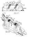
- the manufacturing apparatus 10 identifies a veneer infeed area 12, a production area 14, waste receiving area 16, utensil forming area 18, utensil receiving, sorting and sanding areas 20, 22 and 24 respectively, and a sorting and packaging area 26.
- non-merchantable timber such as Birch and Aspen
- such timber may be generally small in diameter and be of relatively short straight lengths.
- the timber is first cut into balks, that is, pieces or members, of relatively short length (40.5 cm or 16 inches) prior to peeling the veneer.
- Infeed area 12 includes a hot water bath 30 where wood veneer pieces 34 are soaked to soften the lignins. Softened veneer pieces 34 are fed to production area 14, for example on an endless conveyor belt 12a.
- Veneer pieces 34 are received on a die 36 having one or more apertures 38 therein which conform to the shape of the wood utensil being manufactured.
- an apertured stripping plate 40 is securely mounted to and spaced immediately above die 36. Apertures 40a of stripping plate 40 allow free through passage of the projecting punches on the downward utensil-forming stroke B as indicated on Figure 3 and ensures that complete separation of the veneer from the punches occurs on the upward stroke C.
- a vertically operable press 42 is positioned above die 36.
- the lower surface of punch 42a seen in Figure 3 is in the manner of male mold 58 illustrated in Figure 5 , correspondingly shaped to, and in vertical alignment with aperture 38. Operation of press 42 forces punch 42a through aperture 38 thereby shearing veneer 34 to form utensil cut-outs 44, which passes through aperture 38. Cut-outs 44 once pressed through aperture 38 by punch 42a are placed directly into a female mold 48 (best seen in Figure 5 ) which is vertically aligned beneath aperture 38. Mold 48 is formed in or is removably mounted on a platen 50. A series of such platen and mold assemblies are carried by an endless conveyor 52 so as to continuously place a receiving female mold 48 in position beneath aperture 38 to accept utensil cut-outs 44.
- Upper and lower press rolls 54 and 54a respectively engage upper and lower platens 50 and 50a bringing them tightly together.
- Endless conveyors 64a and 64b are laterally disposed on either side of upper and lower male and female mold carrying conveyors 60 and 52 respectively.
- Conveyors 64a and 64b carry a series of 'U' shaped clamps 66 in opposed facing parallel array along a mid-section under platens 50a. As seen in Figure 4 as clamps 66 are brought into engagement with the nested pairs of male and female platens, while they are experiencing the compressive force from press rolls 54, thereby maintaining compression upon the saturated utensil cut-out carried sandwiched therebetween.
- the mating surfaces of platens 50 and 'U' shaped clamps 66 have complimentary beveled surfaces 70a and 70b respectively allowing clamp 66 to readily engage platens 50 and 50a.
- the endless conveyors carrying upper and lower platens 50 and 50a respectively and clamps 66 pass through or adjacent to heaters 76 or other non-contact applied-radiation sources such as for example, a microwave source so that, in one embodiment not intended to be limiting, they are maintained at a temperature of approximately 204 °C (400 degrees Fahrenheit), wherein such a temperature provides for curing of the shaped utensil cut-out in a time of approximately 90 seconds.
- heaters 76 or other non-contact applied-radiation sources such as for example, they are maintained at a temperature of approximately 204 °C (400 degrees Fahrenheit), wherein such a temperature provides for curing of the shaped utensil cut-out in a time of approximately 90 seconds.
- the platens molds are maintained in close nested alignment by means of locking bars 70 or other alignment means projecting from or otherwise mating between the abutting faces.
- the platens and molds may be manufactured from various metallic compositions to enhance wear and heat retention as would be known to one skilled in the art.
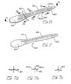
- Each utensil 80 formed by the above process has a handle 82 and a load-engaging member 84 such as the bowl of a spoon or the tines of a fork, etc.
- the handle and the load-engaging member are jointed at a neck 83.
- the illustrated example is a spoon 80'.
- a fork or a combination spoon and fork may be similarly formed.
- Spoon 80' has a handle 82 and a load-engaging member 84 formed as a bowl.
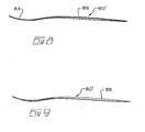
- a dorsal ridge 86 is formed medially of the sides 82a of handle 82.
- Ridge 86 extends well past the neck 83, that is the confluence of the handle 82 with the bowl 84.
- Line A-A may coincide with the greatest stress concentration when the load-engaging member engages a load, such as piercing into food and levering a piece therefrom, when the force is applied by a user grasping the handle and driving the load-engaging member into the food.
- Line A-A has thus been identified as the location where breakage most often occurs in prior art disposable utensils lacking the equivalent of dorsal ridge 86.
- Ridge 86 may advantageously extend one third to one half the length of load-engaging member 84.
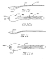
- FIGS 10, 10a and 11 identify a novel utensil 90, which is a combination spoon and fork, which may be referred to as a 'spork'.
- Utensil 90 is a further example of a utensil 80, having a medial dorsal ridge 92 on the handle which, like the ridge in utensil 80' illustrated in Figure 6 , terminates well into the head or bowl 94.
- the forward lip 96 of head 94 has a series of small serrations 98, which act similar to conventional fork tines for spearing or lifting comestibles.
- the bowl 94 of utensil 90 will retain liquids and particulate food for ready consumption.
- Figures 11 and 11a illustrate a slight modification to the utensil of Figure 10 in that the spoon bowl 90a is shallower and the serrations 98a are significantly longer for easier food handling.
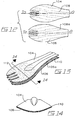
- utensil cut-outs 104 and 106 may be assembled by laminations of thin veneer sheets. Two layers of veneer are employed. The laminations may be cut from different species of wood, for example Aspen and Birch. The wood grain 108 and 108a of each lamination is generally parallel to the longitudinal axis D of the utensil cut-out and when they are superimposed the grain of the different wood species are inherently mismatched.
- a veneer of 1 mm (forty thousands of an inch) thickness can then be utilized for the manufacture of the wooden cut-outs and laminated to produce sturdy eating utensils, with increased resistance to bending and torsion, in particular at the neck constriction of the utensil.
- Bonding together of the utensil cut-outs is accomplished by the use of a non-toxic thermal setting binder 110, for example corn starch or other similarly non-toxic medium, which is applied to the exposed surface 106a of the lower cut-out 106. Utensil cut-outs are then vertically aligned, placed in contact with each other and inserted into the molds.
- a non-toxic thermal setting binder 110 for example corn starch or other similarly non-toxic medium
- the portion of the utensil which comes into contact with food or which is inserted into the mouth may be coated or sealed, for example with an edible wax product as illustrated at 112 on Figure 13 .
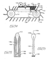
- spoon shapes 112 are stamped out of or otherwise removed from a veneer blank 114 so as to produce a spaced apart parallel array 116 releasably mounted to a common linear member 118 also formed from veneer blank 114.
- veneer blank 114 may be used to produce two arrays 116 by stamping the arrays of spoon shapes 112 in opposed facing relations so as to interleave the opposed facing spoon shapes 112.
- individual spoon shapes or blanks 112 may be removed from member 118 by releasing each spoon blank 112 at a constriction or joint 120.
- the spoon blanks 112 once removed from their corresponding arrays 116, may be loaded into a manually operable press or clamp 122. Once loaded into press 122, the spoon blanks 112 form aligned closely adjacent blocks 124 having the outline of a spoon shape. Two such blocks 124a and 124b are illustrated in Figures 17 and 18 as being loaded within clamp 122, inclined relative to opposed facing clampheads 125a and 125b.
- the clamp 122 is in the form of a bar clamp wherein rotation of handle 126 on threaded spindle 127 translates head 124a in direction F so as to compress spoon blocks 124 against the opposite clamp head 125b.
- a jig 128 is mounted suspended between heads 124a and 124b.
- Head 124a is slidably journalled in jig 128 so as to translate in direction F into a correspondingly sized cavity, thereby pressing against spoon block 124a.
- head 125b compresses spoon block 124b.
- the spoon blocks 124a and 124b are held snugly within a correspondingly shaped cavity 128a within and extending longitudinally along the length of jig 128.
- a cutter head 130 may be translated either manually or along sliding setworks (not shown) so as to pass, in the illustrated embodiment which is not intended to be limiting, the three spaced apart cutter head blades 132 into cutting engagement with the top of each spoon block 124 as the blades 132 translate along the length of channel 128b formed in the top of jig 128.
- the individual blades 132 cut the top of each spoon blank 112 within each spoon block 124 so as to form tines 134.
- a pair of laterally opposite reducing heads 136 are also translated along the upper beveled edges of jig 128 so as to trim the exposed edges 134a from the top of each spoon blank 112 within spoon blocks 124 so as to form flat surfaces 134b thereby altering the shape of the end of each spoon blank 112 into a shape resembling that of a fork.
- the combined utensil then may be used as either a fork or a spoon.
- Reducing heads 136 may be rotatably mounted within brackets 138 on drive axles 136a.
- spoon blocks 124 are loaded onto an endless conveyor 138 between rigid supporting arms 140 mounted around the perimeter of conveyor 138 so as to extend outwardly therefrom.
- Each of supporting arms 140 is shaped so as to sandwich against or cup the ends of spoon blocks 124, so as to hold them snugly therebetween leaving the upper ends of spoon blanks 112 and corresponding upper ends of spoon blocks 124 into notches 140a in arms 140 or protruding above the rigidly outermost ends of supporting arms 140.
- supporting ends 140 are notched with notches 140a so that as conveyor 138 translates in direction H around idler and drive sprockets 142, the upper ends of spoon blocks 124 are translated through rotating saws 144.
- Saws 144 may be for example three saws closely spaced in the manner of saws 132 so as to pass through the notches 140a in the outer ends of supporting arms 140 to thereby form tines 134 in the spoon blanks 112 held within spoon blocks 124.
- spoon blocks 124 are translating on conveyor 138 in direction H they may also be trimmed by the laterally opposite pair of reducing heads 146 (only one of which is shown) so as to form sides 134b on spoon blanks 112.
- the spoon blocks are translated into and along correspondingly shaped cavity 148a within elongate rigid jig 148.
- the upper end of each supporting arm 140 has bevels 140b so as to not interfere with reducing heads 146 as the supporting arms 140 are translated in direction H between the reducing heads and under the saws 144.
- Each of supporting arms 140 may be held in place by, for example, a spring plate 150 also mounted to conveyor 138.
- Supporting arms 140 may be thus formed with the same profile outline as a spoon blank 112 that has been trimmed and sawn, supporting arms 140 and may be connected to conveyor 138 by a neck 152 so as to pass through a corresponding narrow channel 148b between cavity 148a and conveyor belt cavity 148c.
- Conveyor 138 passes through and along cavity 148c.
Claims (6)
- Hölzerner Einmalgebrauchsgegenstand, umfassend:einen Griff mit einem distalen Ende und einem entgegengesetzten Halsende, und entlang einer Längsachse des Gebrauchsgegenstandes liegend,ein Lasteingriffsglied, das sich vom Halsende aus einseitig überstehend entlang der Längsachse erstreckt, so dass es sich in allgemein koplanarer Ausrichtung mit dem Griff befindet und so dass zwischen dem Griff und dem Lasteingriffsglied ein Hals gebildet wird,einen erhöhten dorsalen Rücken, der im Wesentlichen medial entlang des Griffs ausgebildet ist, so dass er durch die Längsachse im Wesentlichen zweigeteilt wird und sich im Wesentlichen entlang des Lasteingriffsgliedes erstreckt,und wobei das Lasteingriffsglied im Wesentlichen schüsselförmig ist und als der Kopf eines Besteckteils zum Eingriff mit Nahrungsmitteln ausgebildet ist,dadurch gekennzeichnet, dass der Gebrauchsgegenstand als Laminierung von nur zwei Lagen von Holzfurnier ausgebildet ist und wobei sich die Laminierung zwischen einer Oberseite des Gebrauchsgegenstandes und einer Unterseite des Gebrauchsgegenstandes befindet, und in dem Griff in einer den Griff im Wesentlichen enthaltenden Ebene ausgebildet ist,und wobei jede Lage von den zwei Lagen des Holzfurniers eine entsprechende Maserung aufweist, die in Bezug zu der Längsachse des Gebrauchsgegenstandes so angewinkelt ist, dass die Maserung allgemein parallel zu der Längsachse des Gebrauchsgegenstandes ist, jedoch nicht auf und entlang dieser liegt, und die Maserungswinkel der zwei Lagen in Bezug zueinander versetzt sind.
- Gebrauchsgegenstand nach Anspruch 1, bei dem die zwei Lagen aus dem Holzfurnier Lagen aus unterschiedlichen Holzarten enthalten.
- Gebrauchsgegenstand nach einem der Ansprüche 1 oder 2, bei dem das Holzfurnier Furnier aus Holz ist, das aus der Gruppe bestehend aus den folgenden nicht-marktgängigen Arten: Birke, Zitterpappel ausgewählt ist.
- Verfahren zur Herstellung eines hölzernen Einmalgebrauchsgegenstandes, umfassend Ausbilden einer Laminierung von nur zwei Lagen von Holzfurnier, so dass bereitgestellt wird:(a) ein Griff mit einem distalen Ende und einem entgegengesetzten Halsende und entlang einer Längsachse liegend,(b) ein Lasteingriffsglied, das sich vom Halsende aus einseitig überstehend entlang der Längsachse erstreckt, so dass es sich in allgemein koplanarer Ausrichtung mit dem Griff befindet und so dass zwischen dem Griff und dem Lasteingriffsglied ein Hals gebildet wird,(c) ein erhöhter dorsaler Rücken im Wesentlichen medial entlang des Griffs, so dass er durch die Längsachse im Wesentlichen zweigeteilt wird und sich im Wesentlichen entlang des Lasteingriffsgliedes erstreckt,wobei sich die Laminierung zwischen einer Oberseite des Gebrauchsgegenstandes und einer Unterseite des Gebrauchsgegenstandes befindet, und in dem Griff in einer den Griff im Wesentlichen enthaltenden Ebene ausgebildet ist,
und wobei während des Verfahrens das Lasteingriffsglied als eine allgemeine Schüsselform ausgebildet wird und als der Kopf eines Besteckteils zum Eingriff mit Nahrungsmitteln ausgebildet wird,
und wobei jede Lage von den zwei Lagen des Holzfurniers eine entsprechende Maserung aufweist, die in Bezug zu der Längsachse des Gebrauchsgegenstandes angewinkelt ist, und wobei während des Verfahrens die Maserung so ausgerichtet wird, dass die Maserung allgemein parallel zu der Längsachse des Gebrauchsgegenstandes ist, jedoch nicht auf und entlang dieser liegt, und die Maserungswinkel der zwei Lagen in Bezug zueinander versetzt sind. - Verfahren nach Anspruch 4, bei dem die zwei Lagen aus dem Holzfurnier Lagen aus unterschiedlichen Holzarten enthalten.
- Verfahren nach einem der Ansprüche 4 oder 5, bei dem das Holzfurnier Furnier aus Holz ist, das aus der Gruppe bestehend aus den folgenden nicht-marktgängigen Arten: Birke, Zitterpappel ausgewählt wird.
Applications Claiming Priority (2)
| Application Number | Priority Date | Filing Date | Title |
|---|---|---|---|
| US49858603P | 2003-08-29 | 2003-08-29 | |
| PCT/CA2004/001569 WO2005020764A1 (en) | 2003-08-29 | 2004-08-27 | Process of production of disposable wooden cutlery and product thereof |
Publications (3)
| Publication Number | Publication Date |
|---|---|
| EP1662947A1 EP1662947A1 (de) | 2006-06-07 |
| EP1662947A4 EP1662947A4 (de) | 2011-05-11 |
| EP1662947B1 true EP1662947B1 (de) | 2014-04-02 |
Family
ID=34272699
Family Applications (1)
| Application Number | Title | Priority Date | Filing Date |
|---|---|---|---|
| EP04761733.7A Not-in-force EP1662947B1 (de) | 2003-08-29 | 2004-08-27 | Verfahren zur herstellung von einwegbesteck aus holz und verfahrensprodukt |
Country Status (8)
| Country | Link |
|---|---|
| US (2) | US20070000136A1 (de) |
| EP (1) | EP1662947B1 (de) |
| JP (1) | JP2007503855A (de) |
| AU (1) | AU2004267891A1 (de) |
| BR (1) | BRPI0414006A (de) |
| CA (1) | CA2536407C (de) |
| NO (1) | NO20061371L (de) |
| WO (1) | WO2005020764A1 (de) |
Families Citing this family (28)
| Publication number | Priority date | Publication date | Assignee | Title |
|---|---|---|---|---|
| US20080000092A1 (en) * | 2006-06-30 | 2008-01-03 | Max Vanguard | Spifork |
| US10057944B2 (en) * | 2009-11-23 | 2018-08-21 | Yiwu Easy Open End Industrial Corp. | Apparatus and methods for conveying and heating objects |
| US11083316B1 (en) | 2010-07-07 | 2021-08-10 | Waddington North America, Inc. | Recyclable and dispensable cutlery utensil |
| US8782907B2 (en) * | 2012-12-20 | 2014-07-22 | Edward Chong | All-in-one multipurpose eating utensil adapted to be separated into pieces |
| US20170095100A1 (en) * | 2015-09-23 | 2017-04-06 | Robert W. White | Disposable eating utensil |
| CN105563599B (zh) * | 2016-01-28 | 2017-08-15 | 三明市德立环保技术开发有限公司 | 毛竹竹片工业化生产竹刀勺产品的设备及生产工艺 |
| CN109475239B (zh) | 2016-04-05 | 2021-07-09 | 沃丁顿北美公司 | 堆叠餐具系统和方法 |
| WO2018200792A1 (en) * | 2017-04-28 | 2018-11-01 | Dwork Michael D | Disposable cutting board and cutlery |
| CN110558801A (zh) * | 2018-06-05 | 2019-12-13 | 歌乐电磁(深圳)有限公司 | 餐具手柄及其餐具 |
| WO2020087052A1 (en) * | 2018-10-25 | 2020-04-30 | Kong Zhicong | Ventilated, stackable, pressing molds |
| TWM572699U (zh) * | 2018-10-26 | 2019-01-11 | 昌盛環保科技股份有限公司 | 叉匙構造 |
| EP3932637A4 (de) * | 2019-02-27 | 2022-04-06 | Hunan Yinsun Bamboo Industry Co., Ltd. | Verfahren und vorrichtung zur verarbeitung von bambusgeschirr |
| JP7254948B2 (ja) * | 2019-02-27 | 2023-04-10 | 湖南銀山竹業有限公司 | 竹製食器の加工成形方法及びその装置 |
| CA3134386A1 (en) | 2019-03-26 | 2020-10-01 | Waddington North America, Inc. | Cutlery dispensing system and method |
| CN111958413B (zh) * | 2019-06-13 | 2022-03-11 | 安徽明德竹木工艺制品有限公司 | 一种扇骨自动打磨上蜡设备 |
| DE102019124699A1 (de) * | 2019-09-13 | 2021-03-18 | Ar Packaging Gmbh | Verfahren zum Herstellen von zumindest teilweise stabförmigen Erzeugnissen aus Papier, Karton oder einem anderen faserhaltigen Material |
| USD932257S1 (en) | 2020-01-28 | 2021-10-05 | Waddington North America, Inc. | Fork |
| USD932849S1 (en) | 2020-01-28 | 2021-10-12 | Waddington North America, Inc. | Spoon |
| USD911785S1 (en) | 2020-01-28 | 2021-03-02 | Waddington North America, Inc. | Knife |
| IT202000018505A1 (it) * | 2020-07-30 | 2022-01-30 | Maurizio Corazzi | Metodo produttivo per oggetti compostabili |
| CN111873117B (zh) * | 2020-07-31 | 2022-07-12 | 湖南省林业科学院 | 一种竹勺餐具加工方法 |
| CN111761680A (zh) * | 2020-07-31 | 2020-10-13 | 国家林业和草原局北京林业机械研究所 | 一种竹刀餐具加工方法 |
| CN111844337A (zh) * | 2020-07-31 | 2020-10-30 | 湖南省林业科学院 | 一种竹叉餐具加工方法 |
| US11696659B2 (en) | 2021-03-11 | 2023-07-11 | World Centric | Molded fiber cutlery |
| JP2022166483A (ja) * | 2021-04-21 | 2022-11-02 | やなぎプロダクツ株式会社 | 木製スプーンの製造方法 |
| CN113635411B (zh) * | 2021-08-04 | 2022-04-12 | 浙江农林大学 | 一种纵向展平竹制备竹铲厨工艺方法 |
| CN113942088B (zh) * | 2021-09-17 | 2022-05-31 | 怀化市恒裕竹木开发有限公司 | 一种往复式竹叉开齿设备 |
| CN115107126B (zh) * | 2022-06-22 | 2023-03-03 | 浙江峰晖竹木制品有限公司 | 竹勺自动断料成型一体机 |
Family Cites Families (71)
| Publication number | Priority date | Publication date | Assignee | Title |
|---|---|---|---|---|
| US1448180A (en) * | 1920-12-24 | 1923-03-13 | Rubwood Inc | Composite laminated structure |
| US1435890A (en) * | 1922-01-17 | 1922-11-14 | Kleen Products Company Inc | Fiber spoon |
| US1461686A (en) * | 1922-01-24 | 1923-07-10 | Reginald W Stone | Tool |
| US1645936A (en) * | 1923-12-24 | 1927-10-18 | Schlesinger Georg | Method of and apparatus for producing cylindrical formations or hollow bodies from veneer or thin sheet wood |
| US1682917A (en) * | 1927-03-28 | 1928-09-04 | Lewis John | Machine for manufacturing wooden spoons |
| US1897809A (en) * | 1929-08-28 | 1933-02-14 | Edna R Lilley | Fiber spoon |
| US2025120A (en) * | 1934-06-20 | 1935-12-24 | Eugene U Knight | Display carton |
| US2095389A (en) * | 1934-07-05 | 1937-10-12 | Southern Kraft Corp | Process of making veneer articles |
| US2291471A (en) * | 1938-11-26 | 1942-07-28 | Oval Wood Dish Corp | Spoon molding machine and method |
| US2346040A (en) * | 1939-12-07 | 1944-04-04 | Berst Forster Dixfield Company | Wooden spoon and method of making the same |
| US2346039A (en) * | 1939-12-07 | 1944-04-04 | Berst Forster Dixfield Company | Method of forming wooden spoons from blanks |
| US2370429A (en) * | 1940-01-04 | 1945-02-27 | Vidal Corp | Laminated structure and method for making such structure |
| US2634497A (en) * | 1940-08-08 | 1953-04-14 | Waldesbuehl Paul Niklaus | Spattle spoon |
| US2398326A (en) * | 1941-08-29 | 1946-04-09 | Cellu Service Corp | Process of making articles from fibrous material |
| US2388485A (en) * | 1941-09-20 | 1945-11-06 | Langley Aviat Corp | Method of making airplane structures |
| US2375994A (en) * | 1944-02-25 | 1945-05-15 | Harry E Johnson | Ski and the method of making the same |
| US2452226A (en) * | 1944-06-15 | 1948-10-26 | M And M Wood Working Company | Laminated product and method of manufacture |
| US2401534A (en) * | 1944-08-04 | 1946-06-04 | John H Mulholland Co | Spoon |
| US2536335A (en) * | 1944-08-28 | 1951-01-02 | Superior Industries | Veneer press |
| US2458864A (en) * | 1945-01-01 | 1949-01-11 | John D Lindsay | Method of making integral molded structures |
| GB583882A (en) * | 1945-06-28 | 1947-01-01 | Chudley & Son Ltd W | Improvements in or relating to receptacles for ice cream and the like |
| US2454113A (en) * | 1945-12-05 | 1948-11-16 | William J Ake | Violin bridge |
| US2593709A (en) * | 1947-07-16 | 1952-04-22 | Chicago Mill & Lumber Co | Veneer handling apparatus |
| DE819812C (de) * | 1949-12-13 | 1951-11-05 | Georg Biller | Fass |
| DE972889C (de) | 1954-07-15 | 1959-10-22 | Nassovia Maschinenfabrik Hanns | Funkenerosionsverfahren zur Herstellung von Bohrungen mit stillstehender oder rotierender Elektrode |
| US2824369A (en) * | 1954-08-12 | 1958-02-25 | Allen M Penrod | Plastic spoon |
| CH361890A (de) | 1958-10-17 | 1962-05-15 | Hugo Pott Gmbh C | Esslöffel |
| US3449194A (en) * | 1965-02-01 | 1969-06-10 | Dow Chemical Co | Process of laminating wood using vinylidene chloride-acrylonitrile copolymer latex based adhesives |
| DE2144085A1 (de) | 1971-09-02 | 1973-03-08 | Siemens Ag | Verfahren zur herstellung von teilen fuer schnittwerkzeuge, wie matrizen, stempel oder auch andere formkoerper mit hintersetzten flaechen, aus einem vorzugsweise planparallele flaechen aufweisenden werkstueck durch elektrothermisches drahterodieren sowie drahterodiermaschine zur durchfuehrung des verfahrens |
| DE2238698C3 (de) | 1972-08-05 | 1981-10-08 | Ateliers des Charmilles, S.A., 1203 Genève | Vorrichtung zum Erodieren konischer Durchbrüche |
| AT329163B (de) | 1973-09-05 | 1976-04-26 | Siemens Ag Oesterreich | Hochfrequenz-heizvorrichtung |
| US3975839A (en) * | 1975-03-12 | 1976-08-24 | Tractioneers, Inc. | Footwear |
| US3964161A (en) * | 1975-09-15 | 1976-06-22 | Wise Colleen M | Wooden camping tool |
| CA1106993A (en) * | 1976-05-26 | 1981-08-11 | Martin M. Sackoff | Method for making a pressure sensitive adhesive coated laminate |
| DK543676A (da) * | 1976-12-03 | 1978-06-04 | K Holbaek | Kompositmateriale |
| US4322409A (en) * | 1978-04-06 | 1982-03-30 | Kureha Kagaku Kogyo Kabushiki Kaisha | Pharmaceutical composition containing a derivative of orthoaminobenzoic acid as an active ingredient |
| USD259575S (en) * | 1980-01-14 | 1981-06-16 | The Quaker Oats Company | Handle for a toy article of flatware |
| US4332409A (en) * | 1980-07-10 | 1982-06-01 | Bms Roasting Equipment Corporation | Combination fork |
| US4589204A (en) * | 1984-11-21 | 1986-05-20 | Courtesy Mold & Tool Corporation | Eating utensil |
| US4809435A (en) * | 1986-05-21 | 1989-03-07 | Printz Gerald L | Eating utensil |
| US4734984A (en) * | 1986-07-28 | 1988-04-05 | Snell John M | Hillbillie's fork |
| US4835860A (en) * | 1987-06-09 | 1989-06-06 | Infeld Andrew L | Carton-opening tool |
| ES1005215Y (es) * | 1987-07-01 | 1989-05-01 | Gil Buj Elena M Del M D | Utillaje alimentario infantil |
| US4771541A (en) * | 1987-07-13 | 1988-09-20 | Myron Bouchakian | Combination fork and knife |
| US4984367A (en) * | 1988-12-16 | 1991-01-15 | Joseph Albanese | Combination utensil |
| US4969268A (en) * | 1989-02-13 | 1990-11-13 | The Kelly Company, Inc. | Kitchen utensil |
| JPH02310001A (ja) * | 1989-05-18 | 1990-12-25 | Seikei Sai | 木製スプーン及びフォークの製造方法 |
| SE464748B (sv) * | 1989-10-13 | 1991-06-10 | Bjoern Persson | Kniv foer smoer, sylt och liknande livsmedel |
| CA2027848A1 (en) * | 1989-10-24 | 1991-04-25 | Berndt Greten | Method for the manufacture of shaped parts |
| NL9000017A (nl) * | 1990-01-03 | 1990-08-01 | Sanders W A Papier | Wegwerpbestek zoals een wegwerplepel, -vork of -eetstokje. |
| FR2657000B1 (fr) | 1990-01-18 | 1992-04-17 | Vulliez Henri | Protection pour objets pointus ou coupant a usage alimentaire. |
| US5075975A (en) * | 1990-03-19 | 1991-12-31 | Wilson Mark P | Eating utensil for the manually impaired and general public |
| US5294467A (en) * | 1992-03-11 | 1994-03-15 | Scoon Corporation | Hand held utensil |
| US5418034A (en) * | 1992-09-30 | 1995-05-23 | Formwood Industries, Inc. | Multiple ply composite veneer laminate with improved dimensional stability |
| DE4316657A1 (de) * | 1993-05-11 | 1994-11-17 | Holzwarenfabrik Deutscheinsied | Besteckteile aus Schälholz, insbesondere in Form einer Gabel, eines Messers oder eines Löffels |
| DE4318043A1 (de) | 1993-05-29 | 1994-12-01 | Saechsische Landesgewerbefoerd | Verfahren zur Herstellung von Flachteilen aus Holz |
| US5373640A (en) * | 1993-11-08 | 1994-12-20 | Cordeiro, Jr.; James H. | Tweezer fork |
| US6254951B1 (en) * | 1994-09-27 | 2001-07-03 | Thomas A. Marmalich | Flexible wood fabric and method of manufacture |
| US5699618A (en) * | 1995-12-27 | 1997-12-23 | Barbera; Michael Edward | Pasta tools |
| US5697659A (en) * | 1996-05-13 | 1997-12-16 | Calagui; Juanito | Eating utensil |
| US5649728A (en) * | 1996-08-02 | 1997-07-22 | Warthen; Benjamin R. | Tong-like eating utensil |
| AT405847B (de) * | 1996-09-16 | 1999-11-25 | Zellform Ges M B H | Verfahren zur herstellung von rohlingen oder formkörpern aus zellulosefasern |
| US5906052A (en) * | 1997-02-25 | 1999-05-25 | Harmon; Douglas A. | Utensil which indicates when the inside of a marshmallow is melted |
| US5860190A (en) * | 1997-03-21 | 1999-01-19 | Cano; Rolando M. | Expanded implement handle grip |
| JP4258787B2 (ja) * | 1997-04-07 | 2009-04-30 | 株式会社 ダイサン | 射出成形金型とその成形品 |
| CA2325374C (en) * | 1999-06-21 | 2007-11-27 | Andrzej Marek Klemarewski | System and method for making compressed wood product |
| US6276734B1 (en) * | 2000-02-04 | 2001-08-21 | Rory F. Krieger | Utilitarian combination utensil |
| CA2316593A1 (en) * | 2000-08-23 | 2002-02-23 | Jean-Pierre Giguere | Structural flexible composite veneer laminate |
| US6649245B2 (en) * | 2001-03-30 | 2003-11-18 | Thomas A. Lenderink | Flexible real wood composition veneer |
| WO2003003883A1 (en) | 2001-07-05 | 2003-01-16 | Alberto Schiavon | Process for making cutlery set with precious stones and such cutlery |
| US7338701B2 (en) * | 2001-10-26 | 2008-03-04 | Uniwood Corporation | Laminated composite wooden material and method of manufacturing material |
-
2004
- 2004-08-27 EP EP04761733.7A patent/EP1662947B1/de not_active Not-in-force
- 2004-08-27 US US10/569,507 patent/US20070000136A1/en not_active Abandoned
- 2004-08-27 CA CA2536407A patent/CA2536407C/en not_active Expired - Fee Related
- 2004-08-27 BR BRPI0414006-0A patent/BRPI0414006A/pt not_active IP Right Cessation
- 2004-08-27 JP JP2006524191A patent/JP2007503855A/ja active Pending
- 2004-08-27 WO PCT/CA2004/001569 patent/WO2005020764A1/en active Application Filing
- 2004-08-27 AU AU2004267891A patent/AU2004267891A1/en not_active Abandoned
-
2006
- 2006-03-27 NO NO20061371A patent/NO20061371L/no not_active Application Discontinuation
-
2008
- 2008-03-20 US US12/076,635 patent/US8079390B2/en not_active Expired - Fee Related
Also Published As
| Publication number | Publication date |
|---|---|
| US20070000136A1 (en) | 2007-01-04 |
| BRPI0414006A (pt) | 2006-10-24 |
| AU2004267891A1 (en) | 2005-03-10 |
| CA2536407C (en) | 2012-07-17 |
| CA2536407A1 (en) | 2005-03-10 |
| US20080178966A1 (en) | 2008-07-31 |
| WO2005020764A1 (en) | 2005-03-10 |
| EP1662947A4 (de) | 2011-05-11 |
| NO20061371L (no) | 2005-03-01 |
| JP2007503855A (ja) | 2007-03-01 |
| EP1662947A1 (de) | 2006-06-07 |
| US8079390B2 (en) | 2011-12-20 |
Similar Documents
| Publication | Publication Date | Title |
|---|---|---|
| EP1662947B1 (de) | Verfahren zur herstellung von einwegbesteck aus holz und verfahrensprodukt | |
| US20060182859A1 (en) | Apparatus and process for forming a decorative impression in a previously-cooked edible product and the product formed thereby | |
| EP1260329A3 (de) | Verfahren zur Herstellung von einer gekrümmten Oberfläche in einer gekrümmten Dekorplatte | |
| PL1995026T3 (pl) | Sposób krojenia batonów produktów spożywczych | |
| CN202640429U (zh) | 蔬菜切丝器 | |
| CN211298243U (zh) | 一种饺子成型设备 | |
| CN210414848U (zh) | 一种竹木自动化切割设备 | |
| CN210389309U (zh) | 一种砖茶分解设备 | |
| CN211761759U (zh) | 一种安全性高的面包用分切机 | |
| EP2028112A1 (de) | Holzbehälter und Herstellungsverfahren dafür | |
| JP2838493B2 (ja) | パン型抜き器 | |
| CN214055424U (zh) | 一种高效防粘刀具 | |
| JP2667519B2 (ja) | フリッチ製造方法 | |
| CN111248611A (zh) | 一种竹质的牙刷手柄及其制备方法 | |
| CN217098007U (zh) | 一种荷叶切割机 | |
| EP0689906A1 (de) | Sicherheitshalter zum Brötchenteilen | |
| CN217064672U (zh) | 一种针叶树种嫁接刀具 | |
| CN210551443U (zh) | 一种高速裁断往复式切药机 | |
| CN204546617U (zh) | 菜板与刀具组合用具 | |
| CN218227483U (zh) | 一种多孔硅胶产品模具内部快速去裁边机构 | |
| CN214604515U (zh) | 一种白及简易切片装置 | |
| CN212015242U (zh) | 一种双刃叉子 | |
| CN216000847U (zh) | 一种曲形竹集材加工用模具及由其组成的热压设备 | |
| CN218138337U (zh) | 一种香菇切片装置 | |
| CN212578678U (zh) | 一种手动切片机用推动装置 |
Legal Events
| Date | Code | Title | Description |
|---|---|---|---|
| PUAI | Public reference made under article 153(3) epc to a published international application that has entered the european phase |
Free format text: ORIGINAL CODE: 0009012 |
|
| 17P | Request for examination filed |
Effective date: 20060310 |
|
| AK | Designated contracting states |
Kind code of ref document: A1 Designated state(s): AT BE BG CH CY CZ DE DK EE ES FI FR GB GR HU IE IT LI LU MC NL PL PT RO SE SI SK TR |
|
| DAX | Request for extension of the european patent (deleted) | ||
| A4 | Supplementary search report drawn up and despatched |
Effective date: 20110408 |
|
| 17Q | First examination report despatched |
Effective date: 20120327 |
|
| GRAP | Despatch of communication of intention to grant a patent |
Free format text: ORIGINAL CODE: EPIDOSNIGR1 |
|
| RIC1 | Information provided on ipc code assigned before grant |
Ipc: A47G 21/04 20060101ALI20130816BHEP Ipc: B27D 1/08 20060101ALI20130816BHEP Ipc: B27M 3/24 20060101ALI20130816BHEP Ipc: A47G 21/02 20060101ALI20130816BHEP Ipc: A47G 21/00 20060101AFI20130816BHEP |
|
| INTG | Intention to grant announced |
Effective date: 20130905 |
|
| GRAS | Grant fee paid |
Free format text: ORIGINAL CODE: EPIDOSNIGR3 |
|
| GRAP | Despatch of communication of intention to grant a patent |
Free format text: ORIGINAL CODE: EPIDOSNIGR1 |
|
| GRAA | (expected) grant |
Free format text: ORIGINAL CODE: 0009210 |
|
| INTG | Intention to grant announced |
Effective date: 20140210 |
|
| AK | Designated contracting states |
Kind code of ref document: B1 Designated state(s): AT BE BG CH CY CZ DE DK EE ES FI FR GB GR HU IE IT LI LU MC NL PL PT RO SE SI SK TR |
|
| REG | Reference to a national code |
Ref country code: GB Ref legal event code: FG4D |
|
| REG | Reference to a national code |
Ref country code: CH Ref legal event code: EP Ref country code: AT Ref legal event code: REF Ref document number: 659564 Country of ref document: AT Kind code of ref document: T Effective date: 20140415 |
|
| REG | Reference to a national code |
Ref country code: IE Ref legal event code: FG4D |
|
| REG | Reference to a national code |
Ref country code: DE Ref legal event code: R096 Ref document number: 602004044746 Country of ref document: DE Effective date: 20140515 |
|
| REG | Reference to a national code |
Ref country code: AT Ref legal event code: MK05 Ref document number: 659564 Country of ref document: AT Kind code of ref document: T Effective date: 20140402 |
|
| REG | Reference to a national code |
Ref country code: NL Ref legal event code: VDEP Effective date: 20140402 |
|
| PG25 | Lapsed in a contracting state [announced via postgrant information from national office to epo] |
Ref country code: GR Free format text: LAPSE BECAUSE OF FAILURE TO SUBMIT A TRANSLATION OF THE DESCRIPTION OR TO PAY THE FEE WITHIN THE PRESCRIBED TIME-LIMIT Effective date: 20140703 Ref country code: CY Free format text: LAPSE BECAUSE OF FAILURE TO SUBMIT A TRANSLATION OF THE DESCRIPTION OR TO PAY THE FEE WITHIN THE PRESCRIBED TIME-LIMIT Effective date: 20140402 Ref country code: FI Free format text: LAPSE BECAUSE OF FAILURE TO SUBMIT A TRANSLATION OF THE DESCRIPTION OR TO PAY THE FEE WITHIN THE PRESCRIBED TIME-LIMIT Effective date: 20140402 Ref country code: CZ Free format text: LAPSE BECAUSE OF FAILURE TO SUBMIT A TRANSLATION OF THE DESCRIPTION OR TO PAY THE FEE WITHIN THE PRESCRIBED TIME-LIMIT Effective date: 20140402 Ref country code: BG Free format text: LAPSE BECAUSE OF FAILURE TO SUBMIT A TRANSLATION OF THE DESCRIPTION OR TO PAY THE FEE WITHIN THE PRESCRIBED TIME-LIMIT Effective date: 20140702 Ref country code: NL Free format text: LAPSE BECAUSE OF FAILURE TO SUBMIT A TRANSLATION OF THE DESCRIPTION OR TO PAY THE FEE WITHIN THE PRESCRIBED TIME-LIMIT Effective date: 20140402 |
|
| PG25 | Lapsed in a contracting state [announced via postgrant information from national office to epo] |
Ref country code: PL Free format text: LAPSE BECAUSE OF FAILURE TO SUBMIT A TRANSLATION OF THE DESCRIPTION OR TO PAY THE FEE WITHIN THE PRESCRIBED TIME-LIMIT Effective date: 20140402 Ref country code: AT Free format text: LAPSE BECAUSE OF FAILURE TO SUBMIT A TRANSLATION OF THE DESCRIPTION OR TO PAY THE FEE WITHIN THE PRESCRIBED TIME-LIMIT Effective date: 20140402 Ref country code: ES Free format text: LAPSE BECAUSE OF FAILURE TO SUBMIT A TRANSLATION OF THE DESCRIPTION OR TO PAY THE FEE WITHIN THE PRESCRIBED TIME-LIMIT Effective date: 20140402 Ref country code: SE Free format text: LAPSE BECAUSE OF FAILURE TO SUBMIT A TRANSLATION OF THE DESCRIPTION OR TO PAY THE FEE WITHIN THE PRESCRIBED TIME-LIMIT Effective date: 20140402 |
|
| PG25 | Lapsed in a contracting state [announced via postgrant information from national office to epo] |
Ref country code: PT Free format text: LAPSE BECAUSE OF FAILURE TO SUBMIT A TRANSLATION OF THE DESCRIPTION OR TO PAY THE FEE WITHIN THE PRESCRIBED TIME-LIMIT Effective date: 20140804 |
|
| REG | Reference to a national code |
Ref country code: DE Ref legal event code: R097 Ref document number: 602004044746 Country of ref document: DE |
|
| PG25 | Lapsed in a contracting state [announced via postgrant information from national office to epo] |
Ref country code: EE Free format text: LAPSE BECAUSE OF FAILURE TO SUBMIT A TRANSLATION OF THE DESCRIPTION OR TO PAY THE FEE WITHIN THE PRESCRIBED TIME-LIMIT Effective date: 20140402 Ref country code: RO Free format text: LAPSE BECAUSE OF FAILURE TO SUBMIT A TRANSLATION OF THE DESCRIPTION OR TO PAY THE FEE WITHIN THE PRESCRIBED TIME-LIMIT Effective date: 20140402 Ref country code: DK Free format text: LAPSE BECAUSE OF FAILURE TO SUBMIT A TRANSLATION OF THE DESCRIPTION OR TO PAY THE FEE WITHIN THE PRESCRIBED TIME-LIMIT Effective date: 20140402 Ref country code: SK Free format text: LAPSE BECAUSE OF FAILURE TO SUBMIT A TRANSLATION OF THE DESCRIPTION OR TO PAY THE FEE WITHIN THE PRESCRIBED TIME-LIMIT Effective date: 20140402 Ref country code: BE Free format text: LAPSE BECAUSE OF FAILURE TO SUBMIT A TRANSLATION OF THE DESCRIPTION OR TO PAY THE FEE WITHIN THE PRESCRIBED TIME-LIMIT Effective date: 20140402 |
|
| PLBE | No opposition filed within time limit |
Free format text: ORIGINAL CODE: 0009261 |
|
| STAA | Information on the status of an ep patent application or granted ep patent |
Free format text: STATUS: NO OPPOSITION FILED WITHIN TIME LIMIT |
|
| 26N | No opposition filed |
Effective date: 20150106 |
|
| PG25 | Lapsed in a contracting state [announced via postgrant information from national office to epo] |
Ref country code: MC Free format text: LAPSE BECAUSE OF FAILURE TO SUBMIT A TRANSLATION OF THE DESCRIPTION OR TO PAY THE FEE WITHIN THE PRESCRIBED TIME-LIMIT Effective date: 20140402 Ref country code: IT Free format text: LAPSE BECAUSE OF FAILURE TO SUBMIT A TRANSLATION OF THE DESCRIPTION OR TO PAY THE FEE WITHIN THE PRESCRIBED TIME-LIMIT Effective date: 20140402 Ref country code: LU Free format text: LAPSE BECAUSE OF FAILURE TO SUBMIT A TRANSLATION OF THE DESCRIPTION OR TO PAY THE FEE WITHIN THE PRESCRIBED TIME-LIMIT Effective date: 20140827 |
|
| REG | Reference to a national code |
Ref country code: CH Ref legal event code: PL |
|
| REG | Reference to a national code |
Ref country code: DE Ref legal event code: R097 Ref document number: 602004044746 Country of ref document: DE Effective date: 20150106 |
|
| PG25 | Lapsed in a contracting state [announced via postgrant information from national office to epo] |
Ref country code: LI Free format text: LAPSE BECAUSE OF NON-PAYMENT OF DUE FEES Effective date: 20140831 Ref country code: CH Free format text: LAPSE BECAUSE OF NON-PAYMENT OF DUE FEES Effective date: 20140831 |
|
| REG | Reference to a national code |
Ref country code: IE Ref legal event code: MM4A |
|
| REG | Reference to a national code |
Ref country code: GB Ref legal event code: 732E Free format text: REGISTERED BETWEEN 20150514 AND 20150520 |
|
| REG | Reference to a national code |
Ref country code: DE Ref legal event code: R081 Ref document number: 602004044746 Country of ref document: DE Owner name: SOCIEDAD COMERCIAL SATCO LIMITADA, CL Free format text: FORMER OWNER: ASPENWARE INC., VERNON, BRITISH COLUMBIA, CA Effective date: 20150520 Ref country code: DE Ref legal event code: R081 Ref document number: 602004044746 Country of ref document: DE Owner name: SOCIEDAD COMERCIAL SATCO LIMITADA, CL Free format text: FORMER OWNER: ASPENWARE INC., VERNON, BRITISH COLUMBIA, CA Effective date: 20140403 |
|
| PG25 | Lapsed in a contracting state [announced via postgrant information from national office to epo] |
Ref country code: SI Free format text: LAPSE BECAUSE OF FAILURE TO SUBMIT A TRANSLATION OF THE DESCRIPTION OR TO PAY THE FEE WITHIN THE PRESCRIBED TIME-LIMIT Effective date: 20140402 |
|
| REG | Reference to a national code |
Ref country code: FR Ref legal event code: TP Owner name: SOCIEDAD COMERCIAL SATCO LIMITADA, CL Effective date: 20150721 |
|
| PG25 | Lapsed in a contracting state [announced via postgrant information from national office to epo] |
Ref country code: IE Free format text: LAPSE BECAUSE OF NON-PAYMENT OF DUE FEES Effective date: 20140827 |
|
| PGFP | Annual fee paid to national office [announced via postgrant information from national office to epo] |
Ref country code: DE Payment date: 20150826 Year of fee payment: 12 |
|
| REG | Reference to a national code |
Ref country code: FR Ref legal event code: PLFP Year of fee payment: 13 |
|
| PG25 | Lapsed in a contracting state [announced via postgrant information from national office to epo] |
Ref country code: TR Free format text: LAPSE BECAUSE OF FAILURE TO SUBMIT A TRANSLATION OF THE DESCRIPTION OR TO PAY THE FEE WITHIN THE PRESCRIBED TIME-LIMIT Effective date: 20140402 Ref country code: HU Free format text: LAPSE BECAUSE OF FAILURE TO SUBMIT A TRANSLATION OF THE DESCRIPTION OR TO PAY THE FEE WITHIN THE PRESCRIBED TIME-LIMIT; INVALID AB INITIO Effective date: 20040827 |
|
| PGFP | Annual fee paid to national office [announced via postgrant information from national office to epo] |
Ref country code: GB Payment date: 20160824 Year of fee payment: 13 |
|
| PGFP | Annual fee paid to national office [announced via postgrant information from national office to epo] |
Ref country code: FR Payment date: 20160715 Year of fee payment: 13 |
|
| REG | Reference to a national code |
Ref country code: DE Ref legal event code: R119 Ref document number: 602004044746 Country of ref document: DE |
|
| PG25 | Lapsed in a contracting state [announced via postgrant information from national office to epo] |
Ref country code: DE Free format text: LAPSE BECAUSE OF NON-PAYMENT OF DUE FEES Effective date: 20170301 |
|
| GBPC | Gb: european patent ceased through non-payment of renewal fee |
Effective date: 20170827 |
|
| REG | Reference to a national code |
Ref country code: FR Ref legal event code: ST Effective date: 20180430 |
|
| PG25 | Lapsed in a contracting state [announced via postgrant information from national office to epo] |
Ref country code: GB Free format text: LAPSE BECAUSE OF NON-PAYMENT OF DUE FEES Effective date: 20170827 |
|
| PG25 | Lapsed in a contracting state [announced via postgrant information from national office to epo] |
Ref country code: FR Free format text: LAPSE BECAUSE OF NON-PAYMENT OF DUE FEES Effective date: 20170831 |